EP1455191A1 - Partially filling device movable to orthogonal coordinate and cylindrical coordinate - Google Patents
Partially filling device movable to orthogonal coordinate and cylindrical coordinate Download PDFInfo
- Publication number
- EP1455191A1 EP1455191A1 EP02781785A EP02781785A EP1455191A1 EP 1455191 A1 EP1455191 A1 EP 1455191A1 EP 02781785 A EP02781785 A EP 02781785A EP 02781785 A EP02781785 A EP 02781785A EP 1455191 A1 EP1455191 A1 EP 1455191A1
- Authority
- EP
- European Patent Office
- Prior art keywords
- liquid
- motor
- driven
- pipet
- attached
- Prior art date
- Legal status (The legal status is an assumption and is not a legal conclusion. Google has not performed a legal analysis and makes no representation as to the accuracy of the status listed.)
- Withdrawn
Links
Images


Classifications
-
- G—PHYSICS
- G01—MEASURING; TESTING
- G01N—INVESTIGATING OR ANALYSING MATERIALS BY DETERMINING THEIR CHEMICAL OR PHYSICAL PROPERTIES
- G01N35/00—Automatic analysis not limited to methods or materials provided for in any single one of groups G01N1/00 - G01N33/00; Handling materials therefor
- G01N35/10—Devices for transferring samples or any liquids to, in, or from, the analysis apparatus, e.g. suction devices, injection devices
- G01N35/1081—Devices for transferring samples or any liquids to, in, or from, the analysis apparatus, e.g. suction devices, injection devices characterised by the means for relatively moving the transfer device and the containers in an horizontal plane
- G01N35/1083—Devices for transferring samples or any liquids to, in, or from, the analysis apparatus, e.g. suction devices, injection devices characterised by the means for relatively moving the transfer device and the containers in an horizontal plane with one horizontal degree of freedom
-
- G—PHYSICS
- G01—MEASURING; TESTING
- G01N—INVESTIGATING OR ANALYSING MATERIALS BY DETERMINING THEIR CHEMICAL OR PHYSICAL PROPERTIES
- G01N35/00—Automatic analysis not limited to methods or materials provided for in any single one of groups G01N1/00 - G01N33/00; Handling materials therefor
- G01N35/0099—Automatic analysis not limited to methods or materials provided for in any single one of groups G01N1/00 - G01N33/00; Handling materials therefor comprising robots or similar manipulators
-
- B—PERFORMING OPERATIONS; TRANSPORTING
- B01—PHYSICAL OR CHEMICAL PROCESSES OR APPARATUS IN GENERAL
- B01L—CHEMICAL OR PHYSICAL LABORATORY APPARATUS FOR GENERAL USE
- B01L3/00—Containers or dishes for laboratory use, e.g. laboratory glassware; Droppers
- B01L3/02—Burettes; Pipettes
- B01L3/021—Pipettes, i.e. with only one conduit for withdrawing and redistributing liquids
-
- G—PHYSICS
- G01—MEASURING; TESTING
- G01N—INVESTIGATING OR ANALYSING MATERIALS BY DETERMINING THEIR CHEMICAL OR PHYSICAL PROPERTIES
- G01N35/00—Automatic analysis not limited to methods or materials provided for in any single one of groups G01N1/00 - G01N33/00; Handling materials therefor
- G01N35/10—Devices for transferring samples or any liquids to, in, or from, the analysis apparatus, e.g. suction devices, injection devices
- G01N2035/1027—General features of the devices
- G01N2035/103—General features of the devices using disposable tips
Definitions
- the present invention relates to a dispensing device which combines a mechanism for expanding the work area of a motor-driven pipet, and a mechanism for selecting the size of a piston pump contained in a motor-driven pipet.
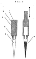
- the motor-driven pipet has the basic structure shown in Fig. 1. It is possible to suck a sample or reagent directly into the cylinder 2 of the motor-driven pipet; however, if cross-contamination is a problem when different kinds of samples or reagents are dispensed, a nozzle 4 is commonly provided on the end of the piston pump and a disposable tip 5 is attached to the nozzle 4 for sucking liquids of samples or reagents 6 into the tip 5.
- the motor-driven pipet is attached to a drive mechanism which can move along orthogonal coordinates as shown in Fig. 2.
- a drive mechanism which can move along orthogonal coordinates as shown in Fig. 2.
- Dispensing devices are widely used in fields which deal with liquids, such as the fields of medical care, pharmaceuticals, and biotechnology, as devices for automatically distributing an accurate amount of liquid to an exact position (container) without humans assistance. Dispensing devices require high speed and high accuracy in distributing liquids.
- the distribution speed depends on the operating speed of the drive system that moves the motor-driven pipet, and the number of motor-driven pipets.
- the operating speed of the drive system is determined by the performance, speed reducing ratio, etc., of the motor of the drive section.
- Dispensing devices using a plurality of motor-driven pipet members are generally called a multi-channel type, and types with 4, 8, 12, or 96 channels are commercially available.
- the accuracy of the dispensing operation depends on the outer diameter of the piston and the space (dead volume) in the tip attached to the nozzle. In other words, it is impossible to accurately dispense a small amount of liquid using a piston pump having a large outer diameter or a tip having a large capacity. This is because dispensing by means of a piston pump utilizes changes in the air volume inside the piston pump.
- the liquid amounts used for ordinary dispensing are often categorized into three levels: from about 0.5 ⁇ l to about 10 ⁇ l, from about 5 ⁇ l to about 200 ⁇ l, and from about 100 ⁇ l to about 1000 ⁇ l.
- tips of different sizes are used for the different levels. Because the tips are different, the nozzles mounted on the motor-driven pipet member and piston pumps are also different. In other words, the shapes of the motor-driven pipets are different.
- a plurality of motor-driven pipets become necessary. Therefore, dispensing devices wherein dispensing members (which correspond to the motor-driven pipets of the present invention) having different shapes are automatically exchanged as disclosed in Japanese Unexamined Patent Publication No. 1996-229414 are also commercially available.
- lab automation has attracted attention in the research and medical fields. By automating liquid dispensing as well as purification, reaction and analysis, it is possible to decrease human error, conduct high-speed, large-volume processing, and reduce labor.
- the lab automation systems currently available are large in scale wherein dispensing devices and industrial conveyance robots, such as those used in automobile manufacturing, are combined. Conveyance robots are used to transfer containers containing pre/post-dispensing samples or reagents among a dispensing device, a reaction device and an analyzer. By organizing the processes of dispensing, reacting and analyzing into individual blocks, and transferring containers containing liquid, etc., these processes can be conducted in a continuous manner.
- Fig. 1 shows a schematic drawing of a piston pump.
- Fig. 2 shows a schematic drawing of a conventional dispensing device.
- Fig. 3 shows a schematic drawing of a basic mechanism of the present invention.
- Reference numbers 1 to 5 in Fig. 3 indicate:
- Fig. 4 shows an example of an application of the basic mechanism of the present invention.
- Fig. 5 shows an example of an application of the basic mechanism of the present invention.
- the present invention relates to a dispensing device that can help automate small- to medium-scale laboratories while overcoming the above-mentioned problems and improve functions and performance in accordance with the automation scale and available budget.
- the above-mentioned problems are attributable to the fact that the drive system to which the motor-driven pipet is attached is formed by three axes, i.e., lateral (forward/backward), horizontal (right/left) and vertical (up/down), and therefore the work area of the motor-driven pipet is restricted by the movement (effective strokes) of the three axes.
- the present invention has succeeded in expanding the work area of the motor-driven pipet by combining an operating mechanism that can move along orthogonal coordinates and an operating mechanism that can move along cylindrical coordinates.
- the mechanism that can move along the orthogonal coordinates uses a mechanism that changes the rotational motion of a motor into linear motion, which is also used in conventional dispensing devices.
- the mechanism that can move along the cylindrical coordinates slows down and otherwise controls the motor's rotational motion and transfers it as rotational motion.
- the present invention comprises a basic drive system wherein a motor-driven pipet member is attached to a linear drive mechanism that can move in one, two or three directions: lateral, horizontal and vertical.
- the basic drive system is attached to a rotatable drive mechanism, and the rotatable drive mechanism is attached to a drive mechanism that can move in directions in which the basic drive system cannot.
- FIG. 3 A concrete example of the basic mechanism of this invention is shown in Fig. 3.
- a motor-driven pipet member 4 is attached to a vertical axis 3
- the vertical axis 3 is attached to a horizontal axis 1
- the horizontal axis 1 is attached to a rotary axis 5
- the rotary axis 5 is attached to a lateral axis 2; however, this combination is only one example of the present invention.
- the functions can be expanded as shown in Fig. 4.
- an analyzer such as a microplate reader 7, as shown in Fig. 4, with a conventional dispensing device, a separate conveying system and dispensing device are required, or the dispensing device must be reconstructed so that the microplate reader 7 falls within the work area of the motor-driven pipet of the dispensing device.
- a sample can be readily transferred to the microplate reader 7 by simply rotating the rotary axis 5.
- FIG. 5 An example of the dispensing device according to claim 6 of the present invention is illustrated in Fig. 5.
- a mechanism wherein dispensing members (corresponding to motor-driven pipets in the present invention) having different shapes are automatically exchanged as disclosed in Japanese Unexamined Patent Publication No. 1996-229414 can be employed.
- the present invention can provide a dispensing device that makes it possible to automate small- to medium-scale laboratories, and to improve function and performance according to the scale and budget of automation.
Landscapes
- Analytical Chemistry (AREA)
- Immunology (AREA)
- Physics & Mathematics (AREA)
- Health & Medical Sciences (AREA)
- Life Sciences & Earth Sciences (AREA)
- Chemical & Material Sciences (AREA)
- Pathology (AREA)
- General Health & Medical Sciences (AREA)
- Biochemistry (AREA)
- General Physics & Mathematics (AREA)
- Engineering & Computer Science (AREA)
- Robotics (AREA)
- Automatic Analysis And Handling Materials Therefor (AREA)
- Feeding, Discharge, Calcimining, Fusing, And Gas-Generation Devices (AREA)
- Devices For Use In Laboratory Experiments (AREA)
Abstract
Description
- 1:
- plunger
- 2:
- cylinder
- 3:
- O-ring
- 4:
- nozzle
- 5:
- tip
- 6:
- liquid
- 1:
- horizontal axis
- 2:
- lateral axis
- 3:
- vertical axis
- 4:
- motor-driven pipet
- 1:
- horizontal axis
- 2:
- lateral axis
- 3:
- vertical axis
- 4:
- motor-driven pipet
- 5:
- rotary axis
- 1:
- horizontal axis
- 2:
- layeral axis
- 3:
- vertical axis
- 4:
- motor-driven pipet
- 5:
- rotary axis
- 6:
- sample (microplate)
- 7:
- analyzer (microplate reader).
- 1:
- basic mechanism of the present invention
- 2:
- operating stage
Claims (6)
- A device for dispensing liquid comprising a drive system having a motor-driven pipet member that can suck and discharge liquid or a tip portion that sucks and discharges liquid movable along orthogonal coordinates defined by three axes, i.e., lateral, horizontal and vertical axes, the device further comprising an additional drive system that enables the work area of the motor-driven pipet member or the tip portion to extend outside the area movable along the orthogonal coordinates.
- A device for dispensing liquid according to Claim 1, wherein the additional drive system is an operating mechanism movable along cylindrical coordinates.
- A device for dispensing liquid according to Claim 1 or 2, wherein the motor-driven pipet member that can suck and discharge liquid or the tip portion that sucks and discharges liquid is automatically exchangeable in accordance with the amount of liquid to be dispensed.
- A device for dispensing liquid according to any one of Claims 1 to 3, wherein a basic drive system that is attached to a linear drive mechanism that can move the motor-driven pipet member that can suck and discharge liquid or the tip portion that sucks and discharges liquid in one, two or three directions, the directions being lateral, horizontal and vertical is further attached to a rotatable drive mechanism, and the rotatable drive mechanism is attached to another drive mechanism that can move in directions in which the basic drive system cannot.
- A device for dispensing liquid according to claim 4, wherein the motor-driven pipet member that can suck and discharge liquid or the tip portion that sucks and discharges liquid is automatically exchangeable according to the amount of liquid to be dispensed.
- A device for dispensing liquid that can optionally expand a work area in which liquid is sucked and discharged by using a plurality of units each having a motor-driven pipet member for liquid sucking and discharging that is automatically exchangeable in accordance with the amount of liquid to be dispensed, wherein a basic drive system that is attached to a linear drive mechanism that can move the motor-driven pipet member for liquid sucking and discharging or a tip portion that sucks and discharges liquid in one, two or three directions, the directions being lateral, horizontal and vertical, is further attached to a rotatable drive mechanism, and the rotatable drive mechanism is attached to another drive mechanism that can move in directions where the basic drive system cannot.
Applications Claiming Priority (3)
| Application Number | Priority Date | Filing Date | Title |
|---|---|---|---|
| JP2001350529 | 2001-11-15 | ||
| JP2001350529A JP2003149255A (en) | 2001-11-15 | 2001-11-15 | Dispensing device that can move to rectangular coordinates and cylindrical coordinates |
| PCT/JP2002/011933 WO2003042705A1 (en) | 2001-11-15 | 2002-11-15 | Partially filling device movable to orthogonal coordinate and cylindrical coordinate |
Publications (2)
| Publication Number | Publication Date |
|---|---|
| EP1455191A1 true EP1455191A1 (en) | 2004-09-08 |
| EP1455191A4 EP1455191A4 (en) | 2006-05-24 |
Family
ID=19163011
Family Applications (1)
| Application Number | Title | Priority Date | Filing Date |
|---|---|---|---|
| EP02781785A Withdrawn EP1455191A4 (en) | 2001-11-15 | 2002-11-15 | Partially filling device movable to orthogonal coordinate and cylindrical coordinate |
Country Status (4)
| Country | Link |
|---|---|
| US (1) | US20050118066A1 (en) |
| EP (1) | EP1455191A4 (en) |
| JP (1) | JP2003149255A (en) |
| WO (1) | WO2003042705A1 (en) |
Cited By (1)
| Publication number | Priority date | Publication date | Assignee | Title |
|---|---|---|---|---|
| WO2017190816A1 (en) * | 2016-05-03 | 2017-11-09 | bioMérieux | Method and system for magnetic extraction of components in a liquid sample |
Families Citing this family (5)
| Publication number | Priority date | Publication date | Assignee | Title |
|---|---|---|---|---|
| JP2005003455A (en) * | 2003-06-10 | 2005-01-06 | Toyobo Co Ltd | Experiment simulation device and experiment simulation program |
| FI116612B (en) | 2004-07-05 | 2006-01-13 | Biohit Oyj | A suction device |
| US7832292B2 (en) * | 2006-05-19 | 2010-11-16 | Npe Systems, Inc. | Polar coordinate positioning system |
| JP5379170B2 (en) * | 2009-02-12 | 2013-12-25 | アークレイ株式会社 | ANALYSIS METHOD, ANALYSIS DEVICE, PROGRAM USED FOR IMPLEMENTING THE ANALYSIS METHOD, STORAGE MEDIUM FOR THE PROGRAM, AND COLLECTION DEVICE |
| JP5709678B2 (en) * | 2011-07-14 | 2015-04-30 | パナソニックヘルスケアホールディングス株式会社 | Dispensing device |
Family Cites Families (24)
| Publication number | Priority date | Publication date | Assignee | Title |
|---|---|---|---|---|
| US4140018A (en) * | 1977-09-07 | 1979-02-20 | Science Spectrum, Inc. | Programmable action sampler system |
| EP0195088B1 (en) * | 1984-09-18 | 1992-12-09 | Sumitomo Electric Industries Limited | Apparatus for sorting cells |
| DE3568999D1 (en) * | 1984-12-27 | 1989-04-27 | Sumitomo Electric Industries | Method and apparatus for incubating cells |
| US4774055A (en) * | 1985-06-26 | 1988-09-27 | Japan Tectron Instruments Corporation | Automatic analysis apparatus |
| US5063024A (en) * | 1985-10-07 | 1991-11-05 | Labsystems Oy | Method and apparatus for immunological determinations |
| US4974458A (en) * | 1987-12-14 | 1990-12-04 | Ajinomoto Company, Inc. | Automatic preparation apparatus and support arm |
| ATE154981T1 (en) * | 1990-04-06 | 1997-07-15 | Perkin Elmer Corp | AUTOMATED MOLECULAR BIOLOGY LABORATORY |
| JP2874328B2 (en) * | 1990-10-29 | 1999-03-24 | 味の素株式会社 | Automatic pretreatment device |
| US5230864A (en) * | 1991-04-10 | 1993-07-27 | Eastman Kodak Company | Gravity assisted collection device |
| US5355439A (en) * | 1991-08-05 | 1994-10-11 | Bio Tek Instruments | Method and apparatus for automated tissue assay |
| EP0555739B1 (en) * | 1992-02-13 | 1998-05-20 | F. Hoffmann-La Roche Ag | Automatic pipetting device |
| JP3091988B2 (en) * | 1993-01-04 | 2000-09-25 | 信越化学工業株式会社 | Automatic measuring device for plasticizer absorption of resin powder |
| JPH08229414A (en) * | 1995-02-28 | 1996-09-10 | Suzuki Motor Corp | Electric pipette holding selection device |
| JPH0998797A (en) * | 1995-10-04 | 1997-04-15 | Takeda Chem Ind Ltd | Enzyme activity measuring device and method for screening enzyme activity inhibitor |
| US7141213B1 (en) * | 1996-07-05 | 2006-11-28 | Beckman Coulter, Inc. | Automated sample processing system |
| US6720186B1 (en) * | 1998-04-03 | 2004-04-13 | Symyx Technologies, Inc. | Method of research for creating and testing novel catalysts, reactions and polymers |
| JPH10253639A (en) * | 1997-03-14 | 1998-09-25 | Prod K Design Jimusho:Kk | Dispensing device |
| JP3273916B2 (en) * | 1998-03-30 | 2002-04-15 | 日本たばこ産業株式会社 | Analysis pretreatment system |
| JP4045475B2 (en) * | 1999-09-06 | 2008-02-13 | 東洋紡績株式会社 | Nucleic acid / protein purification equipment |
| JP2001108619A (en) * | 1999-10-12 | 2001-04-20 | Minolta Co Ltd | Analyzer, sample operation needle and sample removal method |
| DE19955372A1 (en) * | 1999-11-17 | 2001-05-23 | Lre Technology Partner Gmbh | Device for detection of microorganisms in liquid samples has endless belt conveyor which transports analysis plates with sample chambers to analysis zone and dwell zone whose temperature can be regulated |
| US6534307B1 (en) * | 2001-02-08 | 2003-03-18 | Clinomics Biosciences, Inc. | Frozen tissue microarrayer |
| US7160512B2 (en) * | 2001-05-01 | 2007-01-09 | Ngk Insulators, Ltd. | Method for manufacturing biochips |
| US6637476B2 (en) * | 2002-04-01 | 2003-10-28 | Protedyne Corporation | Robotically manipulable sample handling tool |
-
2001
- 2001-11-15 JP JP2001350529A patent/JP2003149255A/en active Pending
-
2002
- 2002-11-15 EP EP02781785A patent/EP1455191A4/en not_active Withdrawn
- 2002-11-15 US US10/495,247 patent/US20050118066A1/en not_active Abandoned
- 2002-11-15 WO PCT/JP2002/011933 patent/WO2003042705A1/en not_active Ceased
Cited By (3)
| Publication number | Priority date | Publication date | Assignee | Title |
|---|---|---|---|---|
| WO2017190816A1 (en) * | 2016-05-03 | 2017-11-09 | bioMérieux | Method and system for magnetic extraction of components in a liquid sample |
| US11572553B2 (en) | 2016-05-03 | 2023-02-07 | bioMérieux | Method and system for magnetic extraction of components in a liquid sample |
| US11584926B2 (en) | 2016-05-03 | 2023-02-21 | bioMérieux | Method and system for magnetic extraction of components in a liquid sample |
Also Published As
| Publication number | Publication date |
|---|---|
| EP1455191A4 (en) | 2006-05-24 |
| US20050118066A1 (en) | 2005-06-02 |
| JP2003149255A (en) | 2003-05-21 |
| WO2003042705A1 (en) | 2003-05-22 |
Similar Documents
| Publication | Publication Date | Title |
|---|---|---|
| US5525515A (en) | Process of handling liquids in an automated liquid handling apparatus | |
| US5334353A (en) | Micropipette device | |
| US7125727B2 (en) | Sample handling tool with piezoelectric actuator | |
| US9079178B2 (en) | Apparatus and methods for pipetting with interchangeability among different pipette tips | |
| EP0138205B1 (en) | Bi-directional liquid sample handling system | |
| US6694197B1 (en) | Single channel reformatter | |
| US12320820B2 (en) | Sample pretreatment device, analysis system including the device, and autosampler | |
| US8007747B2 (en) | Automated fluid handling cartridge, fluid processing system, and methods | |
| WO2000044497A1 (en) | Pipetter | |
| JP4425512B2 (en) | Flexible pipette strip and method of use thereof | |
| US20050118066A1 (en) | Partially filling device movable to orthogonal coordinate and cylindrical coordinate | |
| US20050194407A1 (en) | Precision fluid dispensing system | |
| EP3244214B1 (en) | Device to sample liquids with high-precision in an automated sample analyzer | |
| US4523484A (en) | Dilution pipetter | |
| GB2132346A (en) | Dilution pipetter | |
| CN1359745A (en) | Automatic synthesizer for preparing liquid | |
| JP3389352B2 (en) | Liquid dispensing device | |
| WO2008055613A1 (en) | Fluidic device, and method for the operation thereof | |
| EP4347099B1 (en) | Mixing liquids using an automated liquid handling system | |
| US20230285957A1 (en) | Pipette tip devices and methods | |
| EP4516403A1 (en) | A dosing tool for liquid handling | |
| TW202441177A (en) | Library preparation systems and associated methods | |
| CN121364320A (en) | Multi-sample and multi-reagent bottle compatible wide-volume automatic liquid treatment platform device and treatment process | |
| JPH04161856A (en) | sample collection device | |
| Shephard | Prepper, PhD: DNA purification robotics system |
Legal Events
| Date | Code | Title | Description |
|---|---|---|---|
| PUAI | Public reference made under article 153(3) epc to a published international application that has entered the european phase |
Free format text: ORIGINAL CODE: 0009012 |
|
| 17P | Request for examination filed |
Effective date: 20040609 |
|
| AK | Designated contracting states |
Kind code of ref document: A1 Designated state(s): AT BE BG CH CY CZ DE DK EE ES FI FR GB GR IE IT LI LU MC NL PT SE SK TR |
|
| AX | Request for extension of the european patent |
Extension state: AL LT LV MK RO SI |
|
| A4 | Supplementary search report drawn up and despatched |
Effective date: 20060406 |
|
| RIC1 | Information provided on ipc code assigned before grant |
Ipc: G01N 35/00 20060101ALI20060401BHEP Ipc: B01L 3/02 20060101ALI20060401BHEP Ipc: B01J 4/02 20060101ALI20060401BHEP Ipc: G01N 1/00 20060101ALI20060401BHEP Ipc: G01N 35/10 20060101AFI20030528BHEP |
|
| 17Q | First examination report despatched |
Effective date: 20060901 |
|
| STAA | Information on the status of an ep patent application or granted ep patent |
Free format text: STATUS: THE APPLICATION IS DEEMED TO BE WITHDRAWN |
|
| 18D | Application deemed to be withdrawn |
Effective date: 20070112 |