EP1455142A1 - Air conditioner - Google Patents
Air conditioner Download PDFInfo
- Publication number
- EP1455142A1 EP1455142A1 EP01275011A EP01275011A EP1455142A1 EP 1455142 A1 EP1455142 A1 EP 1455142A1 EP 01275011 A EP01275011 A EP 01275011A EP 01275011 A EP01275011 A EP 01275011A EP 1455142 A1 EP1455142 A1 EP 1455142A1
- Authority
- EP
- European Patent Office
- Prior art keywords
- flow rate
- unit
- indoor
- refrigerant
- outdoor unit
- Prior art date
- Legal status (The legal status is an assumption and is not a legal conclusion. Google has not performed a legal analysis and makes no representation as to the accuracy of the status listed.)
- Withdrawn
Links
Images


Classifications
-
- F—MECHANICAL ENGINEERING; LIGHTING; HEATING; WEAPONS; BLASTING
- F25—REFRIGERATION OR COOLING; COMBINED HEATING AND REFRIGERATION SYSTEMS; HEAT PUMP SYSTEMS; MANUFACTURE OR STORAGE OF ICE; LIQUEFACTION SOLIDIFICATION OF GASES
- F25B—REFRIGERATION MACHINES, PLANTS OR SYSTEMS; COMBINED HEATING AND REFRIGERATION SYSTEMS; HEAT PUMP SYSTEMS
- F25B49/00—Arrangement or mounting of control or safety devices
- F25B49/02—Arrangement or mounting of control or safety devices for compression type machines, plants or systems
-
- F—MECHANICAL ENGINEERING; LIGHTING; HEATING; WEAPONS; BLASTING
- F24—HEATING; RANGES; VENTILATING
- F24F—AIR-CONDITIONING; AIR-HUMIDIFICATION; VENTILATION; USE OF AIR CURRENTS FOR SCREENING
- F24F11/00—Control or safety arrangements
- F24F11/70—Control systems characterised by their outputs; Constructional details thereof
- F24F11/80—Control systems characterised by their outputs; Constructional details thereof for controlling the temperature of the supplied air
- F24F11/83—Control systems characterised by their outputs; Constructional details thereof for controlling the temperature of the supplied air by controlling the supply of heat-exchange fluids to heat-exchangers
- F24F11/84—Control systems characterised by their outputs; Constructional details thereof for controlling the temperature of the supplied air by controlling the supply of heat-exchange fluids to heat-exchangers using valves
-
- F—MECHANICAL ENGINEERING; LIGHTING; HEATING; WEAPONS; BLASTING
- F24—HEATING; RANGES; VENTILATING
- F24F—AIR-CONDITIONING; AIR-HUMIDIFICATION; VENTILATION; USE OF AIR CURRENTS FOR SCREENING
- F24F11/00—Control or safety arrangements
- F24F11/70—Control systems characterised by their outputs; Constructional details thereof
- F24F11/80—Control systems characterised by their outputs; Constructional details thereof for controlling the temperature of the supplied air
- F24F11/83—Control systems characterised by their outputs; Constructional details thereof for controlling the temperature of the supplied air by controlling the supply of heat-exchange fluids to heat-exchangers
-
- F—MECHANICAL ENGINEERING; LIGHTING; HEATING; WEAPONS; BLASTING
- F24—HEATING; RANGES; VENTILATING
- F24F—AIR-CONDITIONING; AIR-HUMIDIFICATION; VENTILATION; USE OF AIR CURRENTS FOR SCREENING
- F24F3/00—Air-conditioning systems in which conditioned primary air is supplied from one or more central stations to distributing units in the rooms or spaces where it may receive secondary treatment; Apparatus specially designed for such systems
- F24F3/06—Air-conditioning systems in which conditioned primary air is supplied from one or more central stations to distributing units in the rooms or spaces where it may receive secondary treatment; Apparatus specially designed for such systems characterised by the arrangements for the supply of heat-exchange fluid for the subsequent treatment of primary air in the room units
- F24F3/065—Air-conditioning systems in which conditioned primary air is supplied from one or more central stations to distributing units in the rooms or spaces where it may receive secondary treatment; Apparatus specially designed for such systems characterised by the arrangements for the supply of heat-exchange fluid for the subsequent treatment of primary air in the room units with a plurality of evaporators or condensers
-
- F—MECHANICAL ENGINEERING; LIGHTING; HEATING; WEAPONS; BLASTING
- F25—REFRIGERATION OR COOLING; COMBINED HEATING AND REFRIGERATION SYSTEMS; HEAT PUMP SYSTEMS; MANUFACTURE OR STORAGE OF ICE; LIQUEFACTION SOLIDIFICATION OF GASES
- F25B—REFRIGERATION MACHINES, PLANTS OR SYSTEMS; COMBINED HEATING AND REFRIGERATION SYSTEMS; HEAT PUMP SYSTEMS
- F25B13/00—Compression machines, plants or systems, with reversible cycle
-
- F—MECHANICAL ENGINEERING; LIGHTING; HEATING; WEAPONS; BLASTING
- F24—HEATING; RANGES; VENTILATING
- F24F—AIR-CONDITIONING; AIR-HUMIDIFICATION; VENTILATION; USE OF AIR CURRENTS FOR SCREENING
- F24F11/00—Control or safety arrangements
- F24F11/50—Control or safety arrangements characterised by user interfaces or communication
- F24F11/54—Control or safety arrangements characterised by user interfaces or communication using one central controller connected to several sub-controllers
-
- F—MECHANICAL ENGINEERING; LIGHTING; HEATING; WEAPONS; BLASTING
- F25—REFRIGERATION OR COOLING; COMBINED HEATING AND REFRIGERATION SYSTEMS; HEAT PUMP SYSTEMS; MANUFACTURE OR STORAGE OF ICE; LIQUEFACTION SOLIDIFICATION OF GASES
- F25B—REFRIGERATION MACHINES, PLANTS OR SYSTEMS; COMBINED HEATING AND REFRIGERATION SYSTEMS; HEAT PUMP SYSTEMS
- F25B2313/00—Compression machines, plants or systems with reversible cycle not otherwise provided for
- F25B2313/023—Compression machines, plants or systems with reversible cycle not otherwise provided for using multiple indoor units
-
- F—MECHANICAL ENGINEERING; LIGHTING; HEATING; WEAPONS; BLASTING
- F25—REFRIGERATION OR COOLING; COMBINED HEATING AND REFRIGERATION SYSTEMS; HEAT PUMP SYSTEMS; MANUFACTURE OR STORAGE OF ICE; LIQUEFACTION SOLIDIFICATION OF GASES
- F25B—REFRIGERATION MACHINES, PLANTS OR SYSTEMS; COMBINED HEATING AND REFRIGERATION SYSTEMS; HEAT PUMP SYSTEMS
- F25B2600/00—Control issues
- F25B2600/02—Compressor control
-
- F—MECHANICAL ENGINEERING; LIGHTING; HEATING; WEAPONS; BLASTING
- F25—REFRIGERATION OR COOLING; COMBINED HEATING AND REFRIGERATION SYSTEMS; HEAT PUMP SYSTEMS; MANUFACTURE OR STORAGE OF ICE; LIQUEFACTION SOLIDIFICATION OF GASES
- F25B—REFRIGERATION MACHINES, PLANTS OR SYSTEMS; COMBINED HEATING AND REFRIGERATION SYSTEMS; HEAT PUMP SYSTEMS
- F25B2600/00—Control issues
- F25B2600/02—Compressor control
- F25B2600/021—Inverters therefor
-
- Y—GENERAL TAGGING OF NEW TECHNOLOGICAL DEVELOPMENTS; GENERAL TAGGING OF CROSS-SECTIONAL TECHNOLOGIES SPANNING OVER SEVERAL SECTIONS OF THE IPC; TECHNICAL SUBJECTS COVERED BY FORMER USPC CROSS-REFERENCE ART COLLECTIONS [XRACs] AND DIGESTS
- Y02—TECHNOLOGIES OR APPLICATIONS FOR MITIGATION OR ADAPTATION AGAINST CLIMATE CHANGE
- Y02B—CLIMATE CHANGE MITIGATION TECHNOLOGIES RELATED TO BUILDINGS, e.g. HOUSING, HOUSE APPLIANCES OR RELATED END-USER APPLICATIONS
- Y02B30/00—Energy efficient heating, ventilation or air conditioning [HVAC]
- Y02B30/70—Efficient control or regulation technologies, e.g. for control of refrigerant flow, motor or heating
Definitions
- the present invention relates to an air conditioner composed of an outdoor unit, a refrigerant flow rate control unit and a single or multiple indoor units.
- the outdoor unit and the single or multiple indoor units are equipped with flow regulators to control the flow rate of refrigerant.
- the outdoor unit and the indoor units are dedicated units which are designed for multiple-unit system.
- a multiple-unit air conditioner may be formed by connecting an outdoor unit for large-scale office air conditioner which is equipped with no flow regulator to a refrigerant flow rate control unit and also connecting a signal or multiple indoor units for home air conditioner which are equipped with no flow regulators to the refrigerant flow rate control unit.
- the refrigerant flow rate control unit has a means of communication with the outdoor unit of the large-scale office air conditioner and a means of communication with the indoor unit of the home air conditioner, then the multiple-unit air conditioner may be implemented at low cost.
- An air conditioner may be characterized by including, at least one indoor unit; an outdoor unit, which controls a flow rate of refrigerant to be supplied to the indoor unit; and a refrigerant flow rate control unit, which controls the outdoor unit and the indoor unit; wherein the refrigerant flow rate control unit may include, an indoor communicating section, which communicates information with the indoor unit, an outdoor communicating section, which communicates information with the outdoor unit, at least one flow regulator, which regulates the flow rate of refrigerant to be supplied to the indoor unit, and a refrigerant flow rate control section, which obtains an operating status of the indoor unit through the indoor communicating section, generates refrigerant flow rate information about the flow rate of refrigerant to be supplied to the indoor unit based on the operating status, controls the flow regulator based on the refrigerant flow rate information, and notifies the outdoor unit of the refrigerant flow rate information through the outdoor communicating section, and wherein the outdoor unit may control the flow rate of refrigerant based on the refrigerant flow rate
- the outdoor unit may be designed for multiple-unit system, in which a single outdoor unit deals with a plurality of indoor units, and the indoor unit may be designed for one-to-one system, in which a single outdoor unit deals with a single indoor unit.
- the outdoor unit may be provided with an outdoor unit communication section, which is designed for the multiple-unit system
- the indoor unit may be provided with an indoor unit communication section, which is designed for the one-to-one system, wherein the outdoor communicating section may be provided with a communication procedure for the outdoor unit communication section, and the indoor communicating section may be provided with a communication procedure for the indoor unit communication section.
- the air conditioner may be characterized by including, a plurality of indoor units; and a plurality of flow regulators provided for the plurality of indoor units, wherein the refrigerant flow rate control unit may be characterized by obtaining the operating status of each of the indoor units through the indoor communicating section, determining the flow rate of refrigerant to be distributed to the each of the indoor units based on the operating status obtained of the each of the indoor units, and controlling the plurality of flow regulators based on the flow rate of refrigerant determined.
- the outdoor unit may be provided with a first system communication section, which uses a first communication system
- the indoor unit may be provided with a second system communication section, which uses a second communication system, which uses a system different from that used by the first communication system
- the outdoor communicating section may be provided with a communication procedure designed for the first system communication section
- the indoor communicating section may be provided with a communication procedure designed for the second system communication section.
- An air conditioner may be characterized by including, an outdoor unit, which is equipped with a compressor for controlling a flow rate of refrigerant; a plurality of refrigerant flow rate control units connected to the outdoor unit; and a plurality of indoor units, each of which is connected to one of the plurality of refrigerant flow rate control units, wherein the outdoor unit may obtain operating information of the plurality of indoor units through the plurality of refrigerant flow rate control units, control the compressor based on the operating information obtained, generate distribution information about a flow rate of refrigerant to be supplied to the plurality of refrigerant flow rate control units, and notify the plurality of refrigerant flow rate control units of the distribution information, and wherein the plurality of refrigerant flow rate control units may include, a plurality of flow regulators for regulating a flow rate of refrigerant to be supplied to the plurality of indoor units, and a refrigerant flow rate distribution section for receiving the distribution information from the outdoor unit, and controlling the plurality of flow regulators
- the outdoor unit may be provided with an outdoor unit communication section designed for multiple-unit system
- the plurality of indoor units may be provided with a plurality of indoor unit communication sections designed for one-to-one system
- the plurality of refrigerant flow rate control units may include, at least one outdoor communicating section, which is provided with a communication procedure for communicating with the outdoor unit communication section, and at least one indoor communicating section, which is provided with a communication procedure for communicating with the plurality of indoor communicating sections.
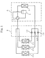
- Fig. 1 is a simplified illustration of a system configuration of an air conditioner according to a first embodiment.
- a reference sign A denotes an outdoor unit which is designed for multiple-unit system
- a reference sign B denotes a refrigerant flow rate control unit
- reference signs C1, C2, C3 denote indoor units which are designed for one-to-one system.
- a reference numeral 1 denotes a compressor which is capable of controlling the volume of refrigerant to be supplied to the indoor units.
- a reference numeral 2 denotes an outdoor heat exchanger
- a reference numeral 3 denotes a four way valve
- reference numerals 11, 12, 13 denote flow regulators.
- the compressor 1 controls the rate of flow of refrigerant by controlling the operating frequency.
- the flow regulators 11, 12, 13 regulate the flow rate of refrigerant to be supplied to the respective indoor units.
- the multiple-unit system is a system in which a single outdoor unit deals with multiple indoor units and that the one-to-one system is a system in which a single outdoor unit deals with a single indoor unit in a one-to-one correspondence.
- the outdoor unit A and the indoor units C1, C2, C3 are equipped with no flow regulators.
- the flow rate of refrigerant for distribution to the respective indoor units C1, C2, C3 is controlled by flow regulators provided in the refrigerant flow rate control unit B.
- Fig. 2 shows a control mechanism of the multiple-unit air conditioner according to the first embodiment.
- a reference sign A denotes an outdoor unit which is designed for multiple-unit system.
- a reference sign B denotes a refrigerant flow rate control unit.
- Reference signs C1, C2, C3 denote indoor units which are designed for one-to-one system.
- a reference sign D denotes communication between the outdoor unit and the refrigerant flow rate control unit.
- Reference signs E1, E2, E3 denote communication between the respective indoor units and the refrigerant flow rate control unit.
- a reference numeral 1 denotes a compressor
- a reference numeral 4 denotes an outdoor unit communication section, which is a means of communication of the outdoor unit.
- a reference numeral 5 denotes an outdoor unit control section, which controls such as the compressor in the outdoor unit.
- Reference numerals 11, 12, 13 denote flow regulators.
- a reference numeral 21 denotes a refrigerant flow rate control section, which controls the operating frequency of the compressor in the outdoor unit and the flow rate of refrigerant to be supplied to the respective indoor units based on the operating information of the indoor units.
- a reference numeral 22 denotes an outdoor communicating section, through which the refrigerant flow rate control unit communicates information with the outdoor unit.
- Reference numerals 31, 32, 33 denote indoor communicating sections, through which the refrigerant flow rate control unit communicates information with the respective indoor units.
- Reference numerals 41, 51, 61 denote indoor unit control sections, which control the respective indoor units.
- Reference numerals 42, 52, 62 denote indoor unit communication sections, which are means of communication of the respective indoor units.
- each indoor unit C1, C2, C3 is collected by the indoor unit control section 41, 51, 61, respectively.
- the operating information is then transmitted to the refrigerant flow rate control unit B through communication E1, E2, E3 between the indoor unit communication section 42, 52, 62 in each indoor unit and the indoor communicating section 31, 32, 33, respectively, in the refrigerant flow rate control unit.
- the refrigerant flow rate control section 21 in the indoor refrigerant flow rate control unit B determines a target operating frequency of the compressor 1 in the outdoor unit A and a target aperture of the flow regulator 11, 12, 13.
- the refrigerant flow rate control section 21 controls the flow rate of refrigerant for distribution.
- the target operating frequency determined above of the compressor 1 is transmitted to the outdoor unit A through the commination D between the outdoor communicating section 22 in the refrigerant flow rate control unit B and the outdoor unit communication section 4 in the outdoor unit.
- the outdoor unit control section 5 in the outdoor unit controls the operating frequency of the compressor 1.
- the outdoor communicating section 22 and the indoor communicating sections 31, 32, 33 in the refrigerant flow rate control unit are independent of each other.
- This allows the system configuration which includes different types of means of communication, in such a case as to use the means of communication designed for multiple-unit system for communication D between the outdoor unit A and the refrigerant flow rate control unit B and the means of communication designed for one-to-one system for communication E1, E2, E3 between each indoor unit C1, C2, C3 and the refrigerant flow rate control unit B.
- one of the characteristic of the air conditioner according to this embodiment is to include the outdoor unit designed for multiple-unit system which is equipped with the volume controllable compressor, the refrigerant flow rate control unit connected to the outdoor unit, and the single or multiple indoor units designed for one-to-one system which are connected to the refrigerant flow rate control unit.
- the outdoor unit and the indoor units are provided with no flow regulators.
- the refrigerant flow rate control unit is equipped with a means of communication with each indoor unit and a flow regulator for each indoor unit. Then, the refrigerant flow rate control unit collects the operating information of each indoor unit and then controls the flow of refrigerant for distribution to each indoor unit at an appropriate rate.
- the refrigerant flow rate control unit is also equipped with a means of communication with the outdoor unit and then controls the operating frequency of the compressor in the outdoor unit to supply all the indoor units with refrigerant at a flow rate required.
- the outdoor unit is provided with a means of communication designed for multiple-unit system
- the indoor units are provided with a means of communication designed for one-to-one system.
- the refrigerant control unit is provided with the different types of means of communication, i.e., one designed for multiple-unit system for communication with the outdoor unit and the other for one-to-one system for communication with the indoor units.
- Fig. 3 is a simplified illustration of a system configuration of an air conditioner according to a second embodiment.
- a reference sign A denotes an outdoor unit designed for multiple-unit system
- reference sings Ba, Bb denote refrigerant flow rate control units
- reference signs C1a, C2a, C3a, C1b, C2b, C3b denote indoor units designed for one-to-one system
- a reference numeral 1 denotes a compressor which is capable of controlling the volume of refrigerant to be supplied to the indoor units.
- a reference numeral 2 denotes a heat exchanger in the outdoor unit.
- a reference numeral 3 denotes a four-way valve.
- Reference signs 11a, 12a, 13a, 11b, 12b, 13b denote flow regulators.
- the outdoor unit A and the indoor units C1a, C2a, C3a, C1b, C2b, C3b are equipped with no flow regulators.
- the flow rate of refrigerant for distribution to the respective indoor units C1a, C2a, C3a, C1b, C2b, C3b is controlled by the flow regulators equipped in the refrigerant flow rate control units Ba, Bb.
- Fig. 4 shows a control mechanism of the air conditioner according to the second embodiment.
- a reference sign A denotes an outdoor unit designed for multiple-unit system
- reference sings Ba, Bb denote refrigerant flow rate control units
- reference signs C1a, C2a, C3a, C1b, C2b, C3b denote indoor units designed for one-to-one system
- a reference sign D denotes communication between the outdoor unit and the refrigerant flow rate control unit.
- Reference signs E1a, E2a, E3a, E1b, E2b, E3b denote communication between the respective indoor units and the refrigerant flow rate control unit.
- a reference numeral 1 denotes a compressor.
- a reference numeral 4 denotes an outdoor unit communication section which is a means of communication of the outdoor unit.
- a reference numeral 5 denotes an outdoor unit control section, which controls such as the compressor in the outdoor unit.
- a reference numeral 6 denotes a refrigerant flow rate control section, which controls the operating frequency of the compressor in the outdoor unit and the flow rate of refrigerant to be supplied to each indoor unit based upon the operating information of the indoor unit.
- Reference signs 11a, 12a, 13a, 11b, 12b, 13b denote flow regulators.
- Reference signs 23a, 23b denote refrigerant flow rate distribution sections.
- Reference signs 22a, 22b denote outdoor communicating sections, through which the refrigerant flow rate control unit communicates information with the outdoor unit.
- Reference signs 31a, 32a, 33a, 31b, 32b, 33b denote indoor communicating sections, through which the refrigerant flow rate control unit communicates information with the respective indoor units.
- Reference signs 41a, 51a, 61a, 41b, 51b, 61b denote indoor unit control section, which control the respective indoor units.
- Reference signs 42a, 52a, 62a, 42b, 52b, 62b denote indoor unit communication sections, which are means of communication of the respective indoor units.
- each indoor unit C1a, C2a, C3a, C1b, C2b, C3b is collected by the indoor unit control section 41a, 51a, 61a, 41b, 51b, 61b, respectively.
- the operating information is then transmitted to the respective refrigerant flow rate control units Ba, Bb through communication E1a, E2a, E3a, E1b, E2b, E3b between the indoor unit control sections 42a, 52a, 62a, 42b, 52b, 62b in the indoor units and the indoor communicating sections 31a, 32a, 33a, 31b, 32b, 33b in the refrigerant flow rate control units Ba, Bb, respectively.
- the operating information of each indoor unit C1a, C2a, C3a, C1b, C2b, C3b obtained through communication E1a, E2a, E3a, E1b, E2b, E3b is also transmitted to the outdoor unit A through communication D between the outdoor communicating sections 22a, 22b in the refrigerant flow rate control units Ba, Bb and the outdoor unit communication section 4 in the outdoor unit, respectively.
- the refrigerant flow rate control section 6 determines a target operating frequency of the compressor 1 and a target flow rate of refrigerant for distribution to the respective refrigerant flow rate control units Ba, Bb.
- the outdoor unit control section 5 controls the operating frequency of the compressor 1.
- the target flow rate of refrigerant determined above for distribution to be supplied to the respective refrigerant flow rate control units Ba, Bb is transmitted to the respective refrigerant flow rate control units Ba, Bb through communication D between the outdoor unit communication section 4 in the outdoor unit and the outdoor communicating section 22a, 22b in the refrigerant flow rate control unit Ba, Bb, respectively.
- the refrigerant flow rate distribution section 23a, 23b determines a target aperture of each flow regulator 11a, 12a, 13a, 11b, 12b, 13b to control the flow rate of refrigerant for distribution.
- the target aperture may thus be determined by the refrigerant flow rate distributing sections 23a, 23b. However, it may alternatively be determined by the refrigerant flow rate control section 6 and transmitted to the respective refrigerant flow rate control units Ba, Bb through communication D.
- the outdoor communicating sections 22a, 22b in the refrigerant flow rate control unit and the indoor communicating sections 31a, 32a, 33a, 31b, 32b, 33b are independent of each other.
- This allows the system configuration which includes different types of means of communication, in such a case as to use a means of communication designed for multiple-unit system for communication D between the outdoor unit A and the refrigerant flow rate control unit B and a means of communication designed for one-to-one system for communication E1, E2, E3 between each indoor unit C1, C2, C3 and the refrigerant flow rate control unit B.
- one of the air conditioner according to this embodiment is to include the outdoor unit designed for multiple-unit system which is equipped with the volume controllable compressor, the refrigerant flow rate control unit connected to the outdoor unit, and the single or multiple indoor units designed for one-to-one system which are connected to the refrigerant flow rate control unit.
- the outdoor unit and the indoor units are equipped with no flow regulators.
- the respective refrigerant flow rate control units transmit to the outdoor unit the operating information of each indoor unit connected.
- the outdoor unit controls the operating frequency of the compressor based upon the operating information of each indoor unit received from the respective refrigerant flow rate control units.
- the outdoor unit transmits to each refrigerant flow rate control unit the volume of refrigerant for distribution according to the air conditioning performance required.
- each refrigerant flow rate control unit further distributes and controls the volume of refrigerant for distribution received from the outdoor unit to the respective indoor units connected.
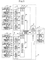
- Fig. 5 shows a control mechanism of an air conditioner according to a third embodiment.
- the simplified illustration of the system configuration thereof is the same as that of Fig. 3 according to the second embodiment.
- the refrigerant flow rate control section 21 obtains the operating information from the indoor units, and determines the target operating frequency of the compressor 1 and the target flow rate of refrigerant for distribution to the respective refrigerant flow rate control units Ba and Bb based upon the operating information obtained. The target operating frequency is then transmitted to the outdoor unit A through communication D.
- the target aperture of each flow regulator 11a, 12a, 13a, 11b, 12b, 13b may be determined by the refrigerant flow rate control section 21. However, it may alternatively be determined by the refrigerant flow rate distributing sections 23a, 23b.
- the air conditioners each include the outdoor unit designed for multiple-unit system and the indoor units designed for one-to-one system. However, that is not a must.
- the air conditioner may be equipped with an outdoor unit designed for one-to-one system and indoor units designed for multiple-unit system, instead.
- the air conditioner includes an outdoor unit which uses the first communication system and an indoor unit which uses the second communication system. Then, the outdoor communicating section of the refrigerant flow rate control unit uses the communication procedure designed for the first communication system, and the indoor communicating section of the refrigerant flow rate control unit uses the communication procedure designed for the second communication system. Therefore, the refrigerant flow rate control unit is allowed to communicate both with the indoor unit communication section and the outdoor unit communication section.
- the refrigerant flow rate control unit is equipped with the flow regulators for the indoor units, respectively. Thus, the flow rate of refrigerator is controlled by the flow regulators for distribution to the respective indoor units.
- the use of existing indoor units designed for one-to-one system is allowed in the air conditioner which includes the outdoor unit designed for multiple-unit system which is equipped with the volume controllable compressor, the refrigerator flow rate control unit connected to the outdoor unit, and at least one of the indoor units connected to the refrigerant flow rate control unit.
- the multiple-unit air conditioner may be implemented at low cost.
- the air conditioner may be implemented at low cost if the refrigerant flow rate control unit is provided with two different types of means of communication, i.e., one designed for multiple-unit system for communicating with the outdoor unit and the other designed for one-to-one system for communicating with the indoor units.
Landscapes
- Engineering & Computer Science (AREA)
- Mechanical Engineering (AREA)
- General Engineering & Computer Science (AREA)
- Chemical & Material Sciences (AREA)
- Combustion & Propulsion (AREA)
- Physics & Mathematics (AREA)
- Thermal Sciences (AREA)
- Air Conditioning Control Device (AREA)
- Compression-Type Refrigeration Machines With Reversible Cycles (AREA)
Abstract
Description
at least one indoor unit;
an outdoor unit, which controls a flow rate of refrigerant to be supplied to the indoor unit; and
a refrigerant flow rate control unit, which controls the outdoor unit and the indoor unit;
wherein the refrigerant flow rate control unit may include,
an indoor communicating section, which communicates information with the indoor unit,
an outdoor communicating section, which communicates information with the outdoor unit,
at least one flow regulator, which regulates the flow rate of refrigerant to be supplied to the indoor unit, and
a refrigerant flow rate control section, which obtains an operating status of the indoor unit through the indoor communicating section, generates refrigerant flow rate information about the flow rate of refrigerant to be supplied to the indoor unit based on the operating status, controls the flow regulator based on the refrigerant flow rate information, and notifies the outdoor unit of the refrigerant flow rate information through the outdoor communicating section, and
wherein the outdoor unit may control the flow rate of refrigerant based on the refrigerant flow rate information.
wherein the outdoor communicating section may be provided with a communication procedure for the outdoor unit communication section, and the indoor communicating section may be provided with a communication procedure for the indoor unit communication section.
a plurality of indoor units; and
a plurality of flow regulators provided for the plurality of indoor units,
wherein the refrigerant flow rate control unit may be characterized by obtaining the operating status of each of the indoor units through the indoor communicating section, determining the flow rate of refrigerant to be distributed to the each of the indoor units based on the operating status obtained of the each of the indoor units, and controlling the plurality of flow regulators based on the flow rate of refrigerant determined.
wherein the outdoor communicating section may be provided with a communication procedure designed for the first system communication section, and the indoor communicating section may be provided with a communication procedure designed for the second system communication section.
an outdoor unit, which is equipped with a compressor for controlling a flow rate of refrigerant;
a plurality of refrigerant flow rate control units connected to the outdoor unit; and
a plurality of indoor units, each of which is connected to one of the plurality of refrigerant flow rate control units,
wherein the outdoor unit may obtain operating information of the plurality of indoor units through the plurality of refrigerant flow rate control units, control the compressor based on the operating information obtained, generate distribution information about a flow rate of refrigerant to be supplied to the plurality of refrigerant flow rate control units, and notify the plurality of refrigerant flow rate control units of the distribution information, and
wherein the plurality of refrigerant flow rate control units may include,
a plurality of flow regulators for regulating a flow rate of refrigerant to be supplied to the plurality of indoor units, and
a refrigerant flow rate distribution section for receiving the distribution information from the outdoor unit, and controlling the plurality of flow regulators based on the distribution information.
at least one outdoor communicating section, which is provided with a communication procedure for communicating with the outdoor unit communication section, and
at least one indoor communicating section, which is provided with a communication procedure for communicating with the plurality of indoor communicating sections.
Claims (7)
- An air conditioner comprising:wherein the refrigerant flow rate control unit includes,at least one indoor unit;an outdoor unit, which controls a flow rate of refrigerant to be supplied to the indoor unit; anda refrigerant flow rate control unit, which controls the outdoor unit and the indoor unit;
an indoor communicating section, which communicates information with the indoor unit,
an outdoor communicating section, which communicates information with the outdoor unit,
at least one flow regulator, which regulates the flow rate of refrigerant to be supplied to the indoor unit, and
a refrigerant flow rate control section, which obtains an operating status of the indoor unit through the indoor communicating section, generates refrigerant flow rate information about the flow rate of refrigerant to be supplied to the indoor unit based on the operating status, controls the flow regulator based on the refrigerant flow rate information, and notifies the outdoor unit of the refrigerant flow rate information through the outdoor communicating section, and
wherein the outdoor unit controls the flow rate of refrigerant based on the refrigerant flow rate information. - The air conditioner according to claim 1, wherein the outdoor unit is designed for multiple-unit system in which a single outdoor unit deals with a plurality of indoor units, and
wherein the indoor unit is designed for one-to-one system in which a single outdoor unit deals with a single indoor unit. - The air conditioner according to claim 2, wherein the outdoor unit is provided with an outdoor unit communication section which is designed for the multiple-unit system,
wherein the indoor unit is provided with an indoor unit communication section which is designed for the one-to-one system,
wherein the outdoor communicating section is provided with a communication procedure for the outdoor unit communication section, and
wherein the indoor communicating section is provided with a communication procedure for the indoor unit communication section. - The air conditioner according to claim 1, further comprising:wherein the refrigerant flow rate control unit obtains the operating status of each of the indoor units through the indoor communicating section, determines the flow rate of refrigerant to be distributed to the each of the indoor units based on the operating status obtained of the each of the indoor units, and controls the plurality of flow regulators based on the flow rate of refrigerant determined.a plurality of indoor units; anda plurality of flow regulators provided for the plurality of indoor units,
- The air conditioner according to claim 1, wherein the outdoor unit is provided with a first system communication section, which uses a first communication system,
wherein the indoor unit is provided with a second system communication section, which uses a second communication system, which uses a system different from a system used by the first communication system,
wherein the outdoor communicating section is provided with a communication procedure designed for the first system communication section, and
wherein the indoor communicating section is provided with a communication procedure designed for the second system communication section. - An air conditioner comprising:wherein the outdoor unit obtains operating information of the plurality of indoor units through the plurality of refrigerant flow rate control units, controls the compressor based on the operating information obtained, generates distribution information about a flow rate of refrigerant to be supplied to the plurality of refrigerant flow rate control units, and notifies the plurality of refrigerant flow rate control units of the distribution information, andan outdoor unit, which is equipped with a compressor for controlling a flow rate of refrigerant;a plurality of refrigerant flow rate control units connected to the outdoor unit; anda plurality of indoor units, each of which is connected to one of the plurality of refrigerant flow rate control units,
wherein the plurality of refrigerant flow rate control units includes,
a plurality of flow regulators for regulating a flow rate of refrigerant to be supplied to the plurality of indoor units, and
a refrigerant flow rate distribution section for receiving the distribution information from the outdoor unit, and controlling the plurality of flow regulators based on the distribution information. - The air conditioner according to claim 6, wherein the outdoor unit is provided with an outdoor unit communication section designed for multiple-unit system,
wherein the plurality of indoor units is provided with a plurality of indoor unit communication sections designed for one-to-one system, and
wherein the plurality of refrigerant flow rate control units includes,
at least one outdoor communicating section, which is provided with a communication procedure for communicating with the outdoor unit communication section, and
at least one indoor communicating section, which is provided with a communication procedure for communicating with the plurality of indoor communicating sections.
Applications Claiming Priority (1)
| Application Number | Priority Date | Filing Date | Title |
|---|---|---|---|
| PCT/JP2001/010971 WO2003052326A1 (en) | 2001-12-14 | 2001-12-14 | Air conditioner |
Publications (2)
| Publication Number | Publication Date |
|---|---|
| EP1455142A1 true EP1455142A1 (en) | 2004-09-08 |
| EP1455142A4 EP1455142A4 (en) | 2006-01-04 |
Family
ID=11738038
Family Applications (1)
| Application Number | Title | Priority Date | Filing Date |
|---|---|---|---|
| EP01275011A Withdrawn EP1455142A4 (en) | 2001-12-14 | 2001-12-14 | AIR CONDITIONING |
Country Status (4)
| Country | Link |
|---|---|
| EP (1) | EP1455142A4 (en) |
| JP (1) | JPWO2003052326A1 (en) |
| CN (1) | CN1218149C (en) |
| WO (1) | WO2003052326A1 (en) |
Families Citing this family (7)
| Publication number | Priority date | Publication date | Assignee | Title |
|---|---|---|---|---|
| KR100697007B1 (en) * | 2004-12-22 | 2007-03-20 | 엘지전자 주식회사 | Apparatus and method for adding outdoor unit capacity of multi air conditioner |
| CN101191644B (en) * | 2006-11-29 | 2011-11-16 | 海尔集团公司 | Multi-split air conditioner coolant flow quantity intelligent dispensing system and its method |
| JP4885901B2 (en) * | 2008-03-31 | 2012-02-29 | 株式会社山武 | Flow control system |
| CN103175290B (en) * | 2013-03-26 | 2016-03-02 | 青岛海尔空调电子有限公司 | Realize the valve cap device of changes in temperature multi-gang air-conditioner simultaneously |
| CN104748239B (en) * | 2015-03-31 | 2017-10-31 | 广东美的暖通设备有限公司 | Multiple on-line system |
| CN105864898A (en) * | 2016-06-01 | 2016-08-17 | 珠海格力电器股份有限公司 | Multi-connected air conditioning unit |
| CN106016536B (en) * | 2016-06-07 | 2018-11-30 | 张安 | The control method of the refrigerant of single compression cylinder air-conditioning |
Family Cites Families (8)
| Publication number | Priority date | Publication date | Assignee | Title |
|---|---|---|---|---|
| JPS62102046A (en) * | 1985-10-28 | 1987-05-12 | Toshiba Corp | Air conditioner |
| JPH03117846A (en) * | 1989-09-29 | 1991-05-20 | Toshiba Corp | Air conditioner |
| JPH03148549A (en) * | 1989-10-31 | 1991-06-25 | Toshiba Corp | Confirmation of wiring and piping for multiple air conditioner |
| GB2241091B (en) * | 1990-02-14 | 1994-01-19 | Toshiba Kk | Air conditioning apparatus connecting one outdoor unit with several indoor units through several refrigerant tubes and signal conductors |
| JPH03236554A (en) * | 1990-02-14 | 1991-10-22 | Toshiba Audio Video Eng Corp | Air-conditioner |
| JPH0476343A (en) * | 1990-07-17 | 1992-03-11 | Toshiba Ave Corp | Air conditioner |
| JPH0476342A (en) * | 1990-07-17 | 1992-03-11 | Toshiba Corp | Air conditioner |
| JPH05203228A (en) * | 1992-01-24 | 1993-08-10 | Mitsubishi Heavy Ind Ltd | Air conditioner |
-
2001
- 2001-12-14 WO PCT/JP2001/010971 patent/WO2003052326A1/en not_active Ceased
- 2001-12-14 EP EP01275011A patent/EP1455142A4/en not_active Withdrawn
- 2001-12-14 JP JP2003542530A patent/JPWO2003052326A1/en active Pending
- 2001-12-14 CN CN018226353A patent/CN1218149C/en not_active Expired - Fee Related
Also Published As
| Publication number | Publication date |
|---|---|
| WO2003052326A1 (en) | 2003-06-26 |
| EP1455142A4 (en) | 2006-01-04 |
| CN1218149C (en) | 2005-09-07 |
| JPWO2003052326A1 (en) | 2005-04-28 |
| CN1492984A (en) | 2004-04-28 |
Similar Documents
| Publication | Publication Date | Title |
|---|---|---|
| US20220003447A1 (en) | Air conditioning system with improved coordination between a plurality of units | |
| US4570448A (en) | Economizer control apparatus | |
| US9121624B2 (en) | Information transfer system for refrigeration air-conditioning apparatus | |
| EP1672293B1 (en) | Multi-air conditioner and group-unit control method thereof | |
| EP1455142A1 (en) | Air conditioner | |
| CN100554803C (en) | The control device of air-conditioning system and air-conditioning system | |
| US20180356115A1 (en) | Air-conditioning control system and remote control device | |
| EP1684030B1 (en) | Method for operating an air conditioner | |
| CN110243030A (en) | air conditioner | |
| JP2021081085A (en) | Air conditioning system | |
| KR101991561B1 (en) | Method and apparatus for controlling air conditioning system | |
| US5956962A (en) | Air conditioner | |
| CN109506348A (en) | Control method of air conditioner air deflector and air conditioner | |
| CN110425687B (en) | Refrigerant adjusting method, refrigerant adjusting controller and air conditioning system | |
| AU2018441289B2 (en) | Air-conditioning system | |
| EP3171091A1 (en) | Air conditioning system, and control method and program therefor | |
| KR20170027164A (en) | Air-conditioner and the method for the same | |
| JP3984945B2 (en) | Air conditioner system | |
| KR101100302B1 (en) | Multi air conditioning system | |
| KR101995584B1 (en) | Air-conditioning system and controlling method thereof | |
| JPH01193563A (en) | Air conditioner | |
| KR102063634B1 (en) | Control method of air-conditioner system | |
| JP3056554B2 (en) | Air conditioner | |
| JP2021032536A (en) | Information processing equipment and programs | |
| EP2896902A1 (en) | Air conditioning system |
Legal Events
| Date | Code | Title | Description |
|---|---|---|---|
| PUAI | Public reference made under article 153(3) epc to a published international application that has entered the european phase |
Free format text: ORIGINAL CODE: 0009012 |
|
| 17P | Request for examination filed |
Effective date: 20030512 |
|
| AK | Designated contracting states |
Kind code of ref document: A1 Designated state(s): AT BE CH CY DE DK ES FI FR GB GR IE IT LI LU MC NL PT SE TR |
|
| RIN1 | Information on inventor provided before grant (corrected) |
Inventor name: MITSUSHIMA, K.,C/O MITSUBISHI DENKI KABUSHIKI K. Inventor name: SHIDA, Y.,C/O MITSUBISHI DENKI KABUSHIKI KAISHA Inventor name: NAGANO, K.,C/O MITSUBISHI DENKI KABUSHIKI KAISHA |
|
| A4 | Supplementary search report drawn up and despatched |
Effective date: 20051118 |
|
| REG | Reference to a national code |
Ref country code: DE Ref legal event code: 8566 |
|
| RAP1 | Party data changed (applicant data changed or rights of an application transferred) |
Owner name: MITSUBISHI DENKI KABUSHIKI KAISHA |
|
| 17Q | First examination report despatched |
Effective date: 20061124 |
|
| STAA | Information on the status of an ep patent application or granted ep patent |
Free format text: STATUS: THE APPLICATION IS DEEMED TO BE WITHDRAWN |
|
| 18D | Application deemed to be withdrawn |
Effective date: 20070405 |