EP1455075A1 - Conduit d'échappement à haute conservation de l'energie thermique - Google Patents
Conduit d'échappement à haute conservation de l'energie thermique Download PDFInfo
- Publication number
- EP1455075A1 EP1455075A1 EP04290513A EP04290513A EP1455075A1 EP 1455075 A1 EP1455075 A1 EP 1455075A1 EP 04290513 A EP04290513 A EP 04290513A EP 04290513 A EP04290513 A EP 04290513A EP 1455075 A1 EP1455075 A1 EP 1455075A1
- Authority
- EP
- European Patent Office
- Prior art keywords
- plane
- exhaust
- distance
- calibrations
- junction
- Prior art date
- Legal status (The legal status is an assumption and is not a legal conclusion. Google has not performed a legal analysis and makes no representation as to the accuracy of the status listed.)
- Granted
Links
Images

Classifications
-
- F—MECHANICAL ENGINEERING; LIGHTING; HEATING; WEAPONS; BLASTING
- F02—COMBUSTION ENGINES; HOT-GAS OR COMBUSTION-PRODUCT ENGINE PLANTS
- F02F—CYLINDERS, PISTONS OR CASINGS, FOR COMBUSTION ENGINES; ARRANGEMENTS OF SEALINGS IN COMBUSTION ENGINES
- F02F1/00—Cylinders; Cylinder heads
- F02F1/24—Cylinder heads
- F02F1/42—Shape or arrangement of intake or exhaust channels in cylinder heads
- F02F1/4264—Shape or arrangement of intake or exhaust channels in cylinder heads of exhaust channels
-
- F—MECHANICAL ENGINEERING; LIGHTING; HEATING; WEAPONS; BLASTING
- F01—MACHINES OR ENGINES IN GENERAL; ENGINE PLANTS IN GENERAL; STEAM ENGINES
- F01N—GAS-FLOW SILENCERS OR EXHAUST APPARATUS FOR MACHINES OR ENGINES IN GENERAL; GAS-FLOW SILENCERS OR EXHAUST APPARATUS FOR INTERNAL-COMBUSTION ENGINES
- F01N13/00—Exhaust or silencing apparatus characterised by constructional features
- F01N13/08—Other arrangements or adaptations of exhaust conduits
- F01N13/10—Other arrangements or adaptations of exhaust conduits of exhaust manifolds
- F01N13/102—Other arrangements or adaptations of exhaust conduits of exhaust manifolds having thermal insulation
-
- F—MECHANICAL ENGINEERING; LIGHTING; HEATING; WEAPONS; BLASTING
- F02—COMBUSTION ENGINES; HOT-GAS OR COMBUSTION-PRODUCT ENGINE PLANTS
- F02F—CYLINDERS, PISTONS OR CASINGS, FOR COMBUSTION ENGINES; ARRANGEMENTS OF SEALINGS IN COMBUSTION ENGINES
- F02F1/00—Cylinders; Cylinder heads
- F02F1/24—Cylinder heads
- F02F1/42—Shape or arrangement of intake or exhaust channels in cylinder heads
- F02F1/4214—Shape or arrangement of intake or exhaust channels in cylinder heads specially adapted for four or more valves per cylinder
Definitions
- the present invention relates to an exhaust duct of internal combustion engine comprising two exhaust pipes and allowing to conserve the thermal energy contained in the gases of combustion.
- exhaust pipes comprising two pipes angled exhaust whose first ends extend respectively, from the fire face of a cylinder head two seats exhaust and whose second ends meet symmetrically by forming a junction in order to recover and channel combustion gases, in particular to the catalytic converter and / or the particles.
- the invention described in document WO O1 / 3306 proposes to maintain the exhaust duct in sheet metal by a few connecting points, thus leaving a substantial part of the free external wall.
- the exhaust pipes thus produced are good market but they do not avoid thermal losses by convection.
- An object of the present invention is then to produce conduits that not only conserve energy thermal combustion gases but also which are likely to be manufactured at low cost.
- the present invention provides an internal combustion engine exhaust duct comprising two bent exhaust pipes whose first ends extend respectively, from the fire face of a cylinder head two exhaust seats, the wall internal bore of said first ends defining two calibrations of diameter D, of the second ends of said two bent exhaust pipes joining symmetrically by forming a junction; said junction is located in the vicinity of a plane P tg which is tangent to two cylinders defined by said calibrations and which intersects said bent exhaust pipes.
- a characteristic of the invention resides in the junction of the two exhaust pipes which is located closest to the seats exhaust, in the direction of gas flow, while respecting the thermomechanical holding possibilities of the breech and the trigger guard of the face fire between the exhaust pipes.
- the gas jet is plated earlier at the top of the exhaust pipes, in the direction of gas flow, so that the surface flux is much lower at the junction of two exhaust pipes.
- X min D / (2cos ⁇
- the exhaust duct according to the invention transfers exhaust gases from the engine cylinder to the manifold exhaust with less heat loss than art ducts prior.
- said cylindrical member is inclined relative to said plane P tg so that said axis A forms an angle ⁇ greater than 90 ° with said plane P tg .
- the obtuse angle thus formed by the first end of the exhaust pipes and the cylindrical member allows a flow of less turbulent gas and therefore with less heat exchange at the walls; compared to a right angle exhaust pipe.
- said angle ⁇ is less than 10 °, and thus limits the angle ⁇ between the axis A and said plane P tg .
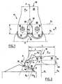
- FIG. 1 shows an exhaust duct 10, said to have a 0 ° pattern, connected to a cylinder head 12 in the upper part of a internal combustion.
- the 0 ° pattern corresponds to the relative arrangement of engine valves and cylinders.
- the exhaust duct 10 has two portions 14, 16 constituting exhaust pipes, the first ends 18, 20 of which are connected to a fire face 22 of the cylinder head 12 of an engine opposite a cylinder, to a distance ep corresponding to the width of the trigger guard. Second ends 24, 26 of said portions meet to form a cylindrical member 28 of axis A and a junction edge 30, up to one end 29 forming an exhaust face and defining a vertical plane P 4 .
- the substantially parabolic shape of the joining edge 30 is determined so as to obtain minimum pressure drops and the cylindrical member has an oblong cross section whose hydraulic diameter is D s .
- D s is defined by the quotient of the surface of the cross section by the perimeter corresponding to said quotient being multiplied by four.
- the axis A of the cylindrical member 28 is included in a vertical plane of symmetry perpendicular to the plane of Figure 1 and by relationship to which the exhaust pipes 14, 16 are the image of one another.
- the exhaust gas jets collected by the two pipes exhaust are guided in substantially the same direction when they open into the cylindrical organ, which generates less exhaust gas turbulence and therefore less heat exchange to the walls.
- An essential characteristic of the invention resides in the position of the junction 30 with respect to the cylinder head 12, this position being defined by a vertical plane P 1 which is perpendicular to the plane of Figure 1, of which the trace and which is tangent to the junction edge 30.
- the position of the vertical plane P 1 is relative to a vertical plane P 2 of which it is spaced by a distance X and which will be detailed with reference to FIG. 2, the distance X being framed by two values, X min and X max .
- the portion 16 of the exhaust pipe 10 forming an exhaust pipe which is extended at its second end 26 by the cylindrical member 28 and whose first end 20 is connected to the fire face 22 of the cylinder head 12 of the engine.
- the internal wall of the first ends 18, 20 connected is bored and defines two calibrations 32 of diameter D. These bores are produced from the internal face of the cylinder head without drawback, since X is greater than X min .
- the calibrations 32 have a central point 34, through which passes the vertical plane P 2 which is also parallel to the axis of the engine cylinder, which vertical plane P 2 also intersects the central point of the calibration of the other exhaust pipe 14 and which is parallel to the vertical plane P 1 which is also found in this FIG. 2.
- the exhaust pipes 14, 16 are connected together so that their junction is located as close as possible to the fire face 22 of the cylinder head 12 and preferably, so that P 1 intersects the axis A in the vicinity of the point P which corresponds to the plane intersection P tg which is tangent to two cylinders 36 defined by said calibrations and which intersects said bent exhaust pipes.
- the axes of symmetry of the two cylinders 36 define a plane P 3 passing through the central point 34 of each of the two calibrations 32.
- the axis of symmetry A of the cylindrical member 28 that is found in Figure 2 forms with the plane P 3 , an angle ⁇ between 90 and 140 °, for example 110 °.
- Combustion gases from the cylinder escaping through a seat exhaust at the fire face 22 of the cylinder head 12, are evacuated very quickly in the cylindrical member 28 which further decreases the heat transfer time between hot combustion gas and pipes exhaust 14, 16.
- the cylinder head 12 has water core passages, not shown, in the vicinity of the exhaust seats and it expands thermally. As a result, the junction between the two pipes exhaust 14, 16 cannot be moved indefinitely close to the seats to respect the thermomechanical behavior of the cylinder head.
- This distance corresponds to the projection of the central point 34 on the plane P tg parallel to the axis A.
- the upper limit distance X max between the plane P 1 and the plane P 2 is defined relative to the length of the cylindrical member 28, the plane P 4 being spaced from the plane P 2 by a distance Y and X max being equal to Y ( ep / (2D + ep-D s )).
- the preferred distance X pref is that which corresponds exactly to the distance between point P and the intersection I of the axis A and the plane P 2 .
- the gas jet is plated earlier at the top of the pipes, in the direction of flow of the exhaust gases, so the surface flux is much lower in the downstream part of the conduit, beyond the junction edge 30 in the direction F.
- the temperature gradient between the gases exhaust and the wall is less and the velocities of these gases are reduced by the fact that the section is greater than the sum of the sections of two separate cylindrical members.
Landscapes
- Engineering & Computer Science (AREA)
- Chemical & Material Sciences (AREA)
- Combustion & Propulsion (AREA)
- Mechanical Engineering (AREA)
- General Engineering & Computer Science (AREA)
- Exhaust Silencers (AREA)
Abstract
Description
- la Figure 1 est une vue schématique de dessus d'un mode de réalisation d'un conduit d'échappement conforme à l'invention ;
- la Figure 2 est une vue schématique verticale en élévation de côté du conduit représenté sur la Figure 1 selon II ; et,
- la Figure 3 est une vue de détail de la Figure 2.
Claims (4)
- Conduit d'échappement de moteur à combustion interne comprenant deux pipes d'échappement coudées dont les premières extrémités sont espacées l'une de l'autre d'une distance ep et prolongent respectivement, à partir de la face feu d'une culasse, deux sièges d'échappement, la paroi interne alésée desdites premières extrémités définissant deux calibrages (32) de diamètre D dont les axes de symétrie définissent un plan P3 incliné d'un angle β par rapport à un plan P2 passant par le centre (34) des deux calibrages (32) parallèlement à l'axe du cylindre dudit moteur, des secondes extrémités desdites deux pipes d'échappement coudées se rejoignant symétriquement en formant une jonction définissant une arête (30), un plan P1, parallèle audit plan P2 et tangent à ladite arête (30) étant espacé dudit plan P2 d'une distance X, ladite jonction étant prolongée par un seul organe cylindrique (28) d'axe A et de diamètre hydraulique Ds jusqu'à une extrémité formant face d'échappement et qui définit un plan P4 parallèle à P2 et espacé de lui d'une distance Y;
caractérisé en ce que ladite distance X est inférieure à Xmax = Y(ep/(2D+ep-Ds)). - Conduit d'échappement selon la revendication 1, caractérisé en ce que, ladite distance X est supérieure à Xmin = D/(2cosβ).
- Conduit d'échappement selon la revendication 1 ou 2, caractérisé en ce que, lesdits calibrages définissant deux cylindres et un plan tangent Ptg auxdits deux cylindres qui coupe lesdites pipes d'échappement coudées, ledit organe cylindrique (28) est incliné par rapport audit plan Ptg de façon que ledit axe A forme un angle α supérieur à 90° avec ledit plan Ptg.
- Conduit d'échappement selon l'une quelconque des revendications 1 à 3, caractérisé en ce que ledit angle β est inférieur à 10°.
Applications Claiming Priority (2)
| Application Number | Priority Date | Filing Date | Title |
|---|---|---|---|
| FR0302454 | 2003-02-28 | ||
| FR0302454A FR2851785B1 (fr) | 2003-02-28 | 2003-02-28 | Conduit d'echappement a haute conservation de l'energie thermique |
Publications (2)
| Publication Number | Publication Date |
|---|---|
| EP1455075A1 true EP1455075A1 (fr) | 2004-09-08 |
| EP1455075B1 EP1455075B1 (fr) | 2006-04-12 |
Family
ID=32799611
Family Applications (1)
| Application Number | Title | Priority Date | Filing Date |
|---|---|---|---|
| EP20040290513 Expired - Lifetime EP1455075B1 (fr) | 2003-02-28 | 2004-02-25 | Conduit d'échappement à haute conservation de l'energie thermique |
Country Status (3)
| Country | Link |
|---|---|
| EP (1) | EP1455075B1 (fr) |
| DE (1) | DE602004000616T2 (fr) |
| FR (1) | FR2851785B1 (fr) |
Citations (3)
| Publication number | Priority date | Publication date | Assignee | Title |
|---|---|---|---|---|
| FR2735815A1 (fr) * | 1995-06-23 | 1996-12-27 | Renault | Moteur a combustion interne multicylindre comportant un dispositif d'introduction d'air dans les conduits d'echappement |
| FR2770256A1 (fr) * | 1997-10-24 | 1999-04-30 | Renault | Moteur a injection directe et allumage commande |
| EP1231373A1 (fr) * | 1999-11-04 | 2002-08-14 | Honda Giken Kogyo Kabushiki Kaisha | Structure d'orifice d'échappement d'un moteur a combustion interne |
-
2003
- 2003-02-28 FR FR0302454A patent/FR2851785B1/fr not_active Expired - Fee Related
-
2004
- 2004-02-25 EP EP20040290513 patent/EP1455075B1/fr not_active Expired - Lifetime
- 2004-02-25 DE DE200460000616 patent/DE602004000616T2/de not_active Expired - Lifetime
Patent Citations (3)
| Publication number | Priority date | Publication date | Assignee | Title |
|---|---|---|---|---|
| FR2735815A1 (fr) * | 1995-06-23 | 1996-12-27 | Renault | Moteur a combustion interne multicylindre comportant un dispositif d'introduction d'air dans les conduits d'echappement |
| FR2770256A1 (fr) * | 1997-10-24 | 1999-04-30 | Renault | Moteur a injection directe et allumage commande |
| EP1231373A1 (fr) * | 1999-11-04 | 2002-08-14 | Honda Giken Kogyo Kabushiki Kaisha | Structure d'orifice d'échappement d'un moteur a combustion interne |
Also Published As
| Publication number | Publication date |
|---|---|
| DE602004000616D1 (de) | 2006-05-24 |
| FR2851785A1 (fr) | 2004-09-03 |
| DE602004000616T2 (de) | 2007-01-25 |
| FR2851785B1 (fr) | 2007-04-13 |
| EP1455075B1 (fr) | 2006-04-12 |
Similar Documents
| Publication | Publication Date | Title |
|---|---|---|
| CA2577507C (fr) | Chambre de combustion d'une turbomachine | |
| FR2928405A1 (fr) | Refroidissement de l'extremite d'une aube. | |
| FR2970031A1 (fr) | Aube profilee de turbomachine avec passages de refroidissement. | |
| FR2786223A1 (fr) | Moteur a combustion, en particulier moteur a combustion pour vehicules automobiles, equipe d'un recyclage des gaz d'echappement | |
| FR2924155A1 (fr) | Aube de turbomachine | |
| FR2950415A1 (fr) | Chambre de combustion de turbomachine aeronautique avec trous de combustion decales ou de debits differents | |
| FR2913063A1 (fr) | Moteur d'aeronef equipe de moyens d'echange thermiques. | |
| WO2004097192A2 (fr) | Echappement pour moteur a combustion interne | |
| CA2670268A1 (fr) | Dispositif reduisant la trainee due au deplacement relatif d'un corps et d'un fluide | |
| FR2696822A1 (fr) | Matrice à tubes profilés pour échangeur de chaleur. | |
| FR3014845A1 (fr) | Systeme de prelevement de fluide | |
| EP2076659B1 (fr) | Ligne d'echappement munie d'un injecteur de carburant et de moyens d'homogeneisation des gaz brules | |
| EP1455075B1 (fr) | Conduit d'échappement à haute conservation de l'energie thermique | |
| FR2506837A1 (fr) | Conduit pour les gaz d'echappement a monter entre un moteur a combustion interne et un turbo-compresseur a gaz d'echappement | |
| FR2874403A1 (fr) | Aube de compresseur ou de turbune a gaz | |
| WO2007118969A1 (fr) | Collecteur d'echappement composite | |
| EP0886732B1 (fr) | Oscillateur fluidique comportant un obstacle a profil ameliore | |
| FR3000522A1 (fr) | Dispositif de liaison a double tube | |
| EP2831473B1 (fr) | Vanne de circulation d'un fluide | |
| FR2957999A1 (fr) | Piston avec un conduit sous joint | |
| EP4689593A1 (fr) | Conduit d'échappement d'un banc d'essai de turbine avec double tube | |
| FR2794275A1 (fr) | Attenuateur de bruit | |
| EP2825801B1 (fr) | Vanne de circulation d'un fluide | |
| EP0179078A1 (fr) | Turbine hydraulique à roue denoyée munie d'un injecteur. | |
| EP2877762B1 (fr) | Vanne de controle moteur a fonctionnement ameliore |
Legal Events
| Date | Code | Title | Description |
|---|---|---|---|
| PUAI | Public reference made under article 153(3) epc to a published international application that has entered the european phase |
Free format text: ORIGINAL CODE: 0009012 |
|
| AK | Designated contracting states |
Kind code of ref document: A1 Designated state(s): AT BE BG CH CY CZ DE DK EE ES FI FR GB GR HU IE IT LI LU MC NL PT RO SE SI SK TR |
|
| AX | Request for extension of the european patent |
Extension state: AL HR LT LV MK |
|
| 17P | Request for examination filed |
Effective date: 20050302 |
|
| AKX | Designation fees paid |
Designated state(s): BE DE GB |
|
| 17Q | First examination report despatched |
Effective date: 20050414 |
|
| GRAP | Despatch of communication of intention to grant a patent |
Free format text: ORIGINAL CODE: EPIDOSNIGR1 |
|
| GRAS | Grant fee paid |
Free format text: ORIGINAL CODE: EPIDOSNIGR3 |
|
| GRAA | (expected) grant |
Free format text: ORIGINAL CODE: 0009210 |
|
| AK | Designated contracting states |
Kind code of ref document: B1 Designated state(s): BE DE GB |
|
| PG25 | Lapsed in a contracting state [announced via postgrant information from national office to epo] |
Ref country code: GB Free format text: LAPSE BECAUSE OF FAILURE TO SUBMIT A TRANSLATION OF THE DESCRIPTION OR TO PAY THE FEE WITHIN THE PRESCRIBED TIME-LIMIT Effective date: 20060412 |
|
| REG | Reference to a national code |
Ref country code: GB Ref legal event code: FG4D Free format text: NOT ENGLISH |
|
| REF | Corresponds to: |
Ref document number: 602004000616 Country of ref document: DE Date of ref document: 20060524 Kind code of ref document: P |
|
| GBV | Gb: ep patent (uk) treated as always having been void in accordance with gb section 77(7)/1977 [no translation filed] |
Effective date: 20060412 |
|
| PLBE | No opposition filed within time limit |
Free format text: ORIGINAL CODE: 0009261 |
|
| STAA | Information on the status of an ep patent application or granted ep patent |
Free format text: STATUS: NO OPPOSITION FILED WITHIN TIME LIMIT |
|
| 26N | No opposition filed |
Effective date: 20070115 |
|
| BERE | Be: lapsed |
Owner name: RENAULT S.A.S. Effective date: 20070228 |
|
| PG25 | Lapsed in a contracting state [announced via postgrant information from national office to epo] |
Ref country code: BE Free format text: LAPSE BECAUSE OF NON-PAYMENT OF DUE FEES Effective date: 20070228 |
|
| PGFP | Annual fee paid to national office [announced via postgrant information from national office to epo] |
Ref country code: DE Payment date: 20170217 Year of fee payment: 14 |
|
| REG | Reference to a national code |
Ref country code: DE Ref legal event code: R119 Ref document number: 602004000616 Country of ref document: DE |
|
| PG25 | Lapsed in a contracting state [announced via postgrant information from national office to epo] |
Ref country code: DE Free format text: LAPSE BECAUSE OF NON-PAYMENT OF DUE FEES Effective date: 20180901 |