EP1454749A1 - Image recording device - Google Patents
Image recording device Download PDFInfo
- Publication number
- EP1454749A1 EP1454749A1 EP02790730A EP02790730A EP1454749A1 EP 1454749 A1 EP1454749 A1 EP 1454749A1 EP 02790730 A EP02790730 A EP 02790730A EP 02790730 A EP02790730 A EP 02790730A EP 1454749 A1 EP1454749 A1 EP 1454749A1
- Authority
- EP
- European Patent Office
- Prior art keywords
- image
- memory
- storage section
- recording apparatus
- recording
- Prior art date
- Legal status (The legal status is an assumption and is not a legal conclusion. Google has not performed a legal analysis and makes no representation as to the accuracy of the status listed.)
- Withdrawn
Links
Images



Classifications
-
- B—PERFORMING OPERATIONS; TRANSPORTING
- B41—PRINTING; LINING MACHINES; TYPEWRITERS; STAMPS
- B41J—TYPEWRITERS; SELECTIVE PRINTING MECHANISMS, i.e. MECHANISMS PRINTING OTHERWISE THAN FROM A FORME; CORRECTION OF TYPOGRAPHICAL ERRORS
- B41J2/00—Typewriters or selective printing mechanisms characterised by the printing or marking process for which they are designed
- B41J2/005—Typewriters or selective printing mechanisms characterised by the printing or marking process for which they are designed characterised by bringing liquid or particles selectively into contact with a printing material
- B41J2/01—Ink jet
- B41J2/21—Ink jet for multi-colour printing
- B41J2/2132—Print quality control characterised by dot disposition, e.g. for reducing white stripes or banding
-
- B—PERFORMING OPERATIONS; TRANSPORTING
- B41—PRINTING; LINING MACHINES; TYPEWRITERS; STAMPS
- B41J—TYPEWRITERS; SELECTIVE PRINTING MECHANISMS, i.e. MECHANISMS PRINTING OTHERWISE THAN FROM A FORME; CORRECTION OF TYPOGRAPHICAL ERRORS
- B41J29/00—Details of, or accessories for, typewriters or selective printing mechanisms not otherwise provided for
- B41J29/38—Drives, motors, controls or automatic cut-off devices for the entire printing mechanism
- B41J29/393—Devices for controlling or analysing the entire machine ; Controlling or analysing mechanical parameters involving printing of test patterns
-
- G—PHYSICS
- G06—COMPUTING OR CALCULATING; COUNTING
- G06K—GRAPHICAL DATA READING; PRESENTATION OF DATA; RECORD CARRIERS; HANDLING RECORD CARRIERS
- G06K15/00—Arrangements for producing a permanent visual presentation of the output data, e.g. computer output printers
- G06K15/02—Arrangements for producing a permanent visual presentation of the output data, e.g. computer output printers using printers
- G06K15/027—Test patterns and calibration
-
- G—PHYSICS
- G06—COMPUTING OR CALCULATING; COUNTING
- G06K—GRAPHICAL DATA READING; PRESENTATION OF DATA; RECORD CARRIERS; HANDLING RECORD CARRIERS
- G06K15/00—Arrangements for producing a permanent visual presentation of the output data, e.g. computer output printers
- G06K15/02—Arrangements for producing a permanent visual presentation of the output data, e.g. computer output printers using printers
- G06K15/10—Arrangements for producing a permanent visual presentation of the output data, e.g. computer output printers using printers by matrix printers
- G06K15/102—Arrangements for producing a permanent visual presentation of the output data, e.g. computer output printers using printers by matrix printers using ink jet print heads
-
- G—PHYSICS
- G06—COMPUTING OR CALCULATING; COUNTING
- G06K—GRAPHICAL DATA READING; PRESENTATION OF DATA; RECORD CARRIERS; HANDLING RECORD CARRIERS
- G06K15/00—Arrangements for producing a permanent visual presentation of the output data, e.g. computer output printers
- G06K15/02—Arrangements for producing a permanent visual presentation of the output data, e.g. computer output printers using printers
- G06K15/10—Arrangements for producing a permanent visual presentation of the output data, e.g. computer output printers using printers by matrix printers
- G06K15/102—Arrangements for producing a permanent visual presentation of the output data, e.g. computer output printers using printers by matrix printers using ink jet print heads
- G06K15/105—Multipass or interlaced printing
- G06K15/107—Mask selection
-
- G—PHYSICS
- G06—COMPUTING OR CALCULATING; COUNTING
- G06K—GRAPHICAL DATA READING; PRESENTATION OF DATA; RECORD CARRIERS; HANDLING RECORD CARRIERS
- G06K15/00—Arrangements for producing a permanent visual presentation of the output data, e.g. computer output printers
- G06K15/02—Arrangements for producing a permanent visual presentation of the output data, e.g. computer output printers using printers
- G06K15/18—Conditioning data for presenting it to the physical printing elements
- G06K15/1801—Input data handling means
- G06K15/1817—Buffers
Definitions
- the present invention relates to an image recording apparatus in which a plurality of recording heads are joined to form a composite recording head having a large recording width and an image is recorded, particularly to an image recording apparatus in which a positional shift is not caused between recorded images printed by the respective recording heads although the recording heads are not accurately positioned.
- An object of the present invention is to consider the above-described problems and to provide an image recording apparatus in which an image transfer position of a storage section for storing image information is changed in accordance with a positional shift between nozzles in printing binarized input image data with each nozzle of a recording head, so that multivalued image geometric correction described above is not required.
- an image recording apparatus which prints an image using a composite recording head formed by joining a plurality of recording heads having a plurality of nozzles to discharge ink so as to have an overlapping region in about the same direction as an arrangement direction of the nozzles
- the image recording apparatus comprising: an input image storage section which stores whole image information input into the image recording apparatus; a temporary image storage section into which the image information for a recording width printable by each recording head in the image information stored in the input image storage section is transferred and temporarily stored; a test pattern reading section which reads a test pattern printed by the composite recording head; a position information calculation section which calculates position information including a transfer start address and a transfer destination address of each storage section and a width of the overlapping region for use in transferring the image information into the temporary image storage section from the input image storage section from information of the read test pattern; and a position information storage section which stores the position information calculated by the position information calculation section.
- an image recording apparatus relates to the image recording apparatus according to the first aspect of the present invention, and further comprises a mask pattern production section which generates a mask pattern to mask the transferred image information by a dot unit so as to prevent the nozzles from discharging the ink, and the recording head prints the image based on the image information via the mask pattern.
- an image recording apparatus relates to the image recording apparatus according to the first aspect of the present invention, and comprises a plurality of composite recording heads, and the respective composite recording heads record inks in different colors.
- FIG. 1 is a diagram showing a constitution of a first embodiment of the present invention.
- first, binary test pattern image data of a straight line extending in an arrangement direction of nozzles of a first head (hereinafter referred to as the head (1) 13) and a second head (hereinafter referred to as the head (2) 16) is input into an input image memory 10.
- a transfer start position in which correction of a positional shift between the heads (1) 13 and (2) 16 is not considered (address on a memory indicating a top position of each line during the reading from the input image memory 10), a transfer destination position (address on the memory indicating the top position of each line during writing into temporary memories 12, 15), and a width of the overlapping region (initial value is 0) are stored.
- An image transfer section 11 refers to the position information stored in the position memory 11, and transfers input test pattern image data to two temporary memories 12, 15 via the image transfer section 11 to print a test pattern in the heads (1) 13 and (2) 16. Moreover, a test pattern 14 (see FIG.
- test pattern reading sections 19 such as a scanner and a digital camera
- the read image data is analyzed by a position calculation section 18.
- a position calculation section 18 By this analysis, as shown in FIG. 4, a relative position relationship between nozzles is obtained, and the transfer start position in the input image memory 10, the transfer destination positions in the temporary memories 12, 15, and the width of the overlapping region between the heads (1) 13 and (2) 16 are calculated from this position relationship to rewrite values stored in the position memory 17. It is to be noted that details of a calculation method will be described later with reference to FIG. 4.
- binarized image data is input into the input image memory 10, the position information stored in the position memory 17 is read, and the input image data is accordingly transferred to the temporary memories 12, 15, and printed by the heads (1) 13 and (2) 16.
- FIG. 2 is a diagram showing a constitution of a second embodiment of the present invention.
- binary test pattern image data of a straight line extending in an arrangement direction of nozzles of heads (1) 24 and (2) 28 is input into an input image memory 20.
- a transfer start position in which the correction of the positional shift between the heads (1) 24 and (2) 28 is not considered (address on the memory indicating the top position of each line during the reading from the input image memory 20)
- a transfer destination position (address on the memory indicating the top position of each line during writing into temporary memories 22, 26)
- the width of the overlapping region initial value is 0
- An image transfer section 21 refers to the position information stored in the position memory 29, and transfers input test pattern image data to two temporary memories 22, 26 via the image transfer section 21.
- a mask pattern production section 30 generates a mask pattern capable of transferring the image data as such without masking the data, and subsequently transfers the pattern to masking sections 23, 27. Furthermore, the mask pattern is adapted to the data (as such here) in the masking sections 23, 27 which have received the image data from the temporary memories 22, 26, and printed by the heads (1) 24 and (2) 27.
- a test pattern 25 (see FIG. 4) printed in this manner is read by test pattern reading sections 32 such as a scanner and a digital camera, and the read image data is analyzed by a position calculation section 31.
- a relative position relationship between nozzles is obtained, and the transfer start position in the input image memory 20, the transfer destination positions in the temporary memories 22, 26, and the width of the overlapping region between the heads (1) 24 and (2) 28 are calculated from the position relationship to rewrite values stored in the position memory 29.
- binarized image data is input into the input image memory 20, the position information stored in the position memory 29 is read, and the input image data is accordingly transferred to the temporary memories 22, 26.
- the mask pattern production section 30 as shown in FIG. 7, the mask patterns for the heads 1 and 2 are generated.
- the mask pattern has a size equal to that of the temporary memory for each head, white dots pass the image data in the corresponding position as such, and hatched dots mean that the image data of the corresponding position is converted to data which is not to be printed.
- the mask patterns of the heads 1 and 2 are prepared in such a manner that a portion other than an overlapping portion is the white dot, and the hatched dots are complementary by two heads in the overlapping portion.
- the prepared mask patterns are transferred to the masking sections 23, 27. Furthermore, the mask patterns are adapted to the data in the masking sections 23, 27 which have received the image data from the temporary memories 22, 26, and only the dots to be printed are printed by the heads (1) 24 and (2) 27.
- FIG. 3 is a schematic diagram showing a composite recording head formed by joining a plurality of recording heads (1) and (2) so as to have an overlapping region in about the same direction as the arrangement direction of the nozzles.
- the recording heads (1) and (2) are not accurately positioned, and are arranged in inclined states.
- FIG. 4 is a diagram showing data obtained by reading the test pattern printed using the recording heads of FIG. 3 by the reading section. A method of obtaining the relative positions of the respective nozzles of the recording heads will be described with reference to FIG. 4.
- Each of the recording heads 1 and 2 has eight nozzles. A gravity center position of the printed dot is obtained in order to obtain each nozzle position accurately.
- a conveying direction of a sheet is set to an X-axis, a direction crossing this axis at right angles is set to a Y-axis, and the nozzle position of each recording head is obtained from the printed test pattern.
- FIG. 4 is a diagram showing data obtained by reading the test pattern printed using the recording heads of FIG. 3 by the reading section.
- a coordinate of a nozzle 41 in an end of the recording head 1 is (X41, 0)
- a coordinate of a nozzle 58 in an end of the recording head 2 is (0, Y58)
- a coordinate position of each nozzle is obtained.
- the coordinate of a nozzle i is obtained as (Xi, Yi)
- a distance between the nozzles is obtained by calculation of a distance between centers of gravity of adjacent dots.
- Character i denotes an arbitrary nozzle.
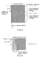
- FIG. 5 shows the image data stored in the input image memory.
- the X-axis indicates a line direction of the image data (i.e., arrangement direction of the image data to be printed in a sheet feed direction), and the Y-axis indicates the arrangement direction of the nozzles.
- the transfer start position in the input image memory of the nozzle i is a top pixel of a [Yi/P]-th line. It is to be noted that [Yi/P] indicates an integer obtained by rounding a real number Yi/P, and [] is used in a similar meaning hereinafter.
- FIG. 6 shows the temporary memory for a recording head.
- the transfer destination position of the nozzle i is an [Xi/P]-th position of a [Yi/P]-th line of the temporary memory. That is, pixel data of the [Yi/P]-th line of the input image memory for the nozzle i of FIG. 5 is transferred to an [Xi/P]-th pixel position of the [Yi/P]-th line of the temporary memory in order. In this manner, the pixel data is successively transferred for each line in an X-axis direction. When the pixel data is transferred to the temporary memory from the input image memory in all lines, the transfer ends.
- FIG. 7 is an explanatory view of the mask pattern according to the embodiment of the present invention.
- An upper pattern is an example of the mask pattern for the head 1
- a lower pattern is an example of the mask pattern for the head 2
- hatched dot positions indicate that any dot is not printed. Since the heads 1 and 2 print the same image in the overlapping region, non-printed dot positions are just reversed in the overlapping region in order to assign the printing between two heads so that double printing is avoided.
- the width of the overlapping region has to be obtained to accordingly generate an optimum mask pattern in the mask pattern production section.
- An overlapping width of two heads can be calculated as [(Y48-Y51)/P] from the coordinate of the lowest nozzle of the head 1 and that of the top nozzle of the head 2.
- any time-consuming geometric correction does not have to be performed with respect to the image, and high-speed printing is possible. Furthermore, since any device for the geometric correction is not required, cost of the recording apparatus can be reduced.
- an image recording apparatus can be speeded up, and cost can be reduced.
Landscapes
- Engineering & Computer Science (AREA)
- Physics & Mathematics (AREA)
- General Engineering & Computer Science (AREA)
- General Physics & Mathematics (AREA)
- Theoretical Computer Science (AREA)
- Mathematical Physics (AREA)
- Quality & Reliability (AREA)
- Ink Jet (AREA)
- Record Information Processing For Printing (AREA)
Abstract
There is disclosed an image recording apparatus
comprising an input image memory, a temporary memory, a
position memory to store a transfer start position in
the input image memory and a transfer destination
position in the temporary memory and an overlapping
width between recording heads for each nozzle in a case
where some of images recorded in the input image memory
are transferred to the temporary memory, a scanner, a
position calculation section which calculates the
transfer start position and the transfer destination
position and the overlapping width from read test
pattern data, and an image transfer section which
transfers the images of the input image memory to the
temporary memory in accordance with the transfer start
position of the position memory, so that any geometric
correction of a multivalued image does not have to be
performed, any device for the correction is not
required, therefore the image recording apparatus can
be speeded up, and cost can be reduced.
Description
The present invention relates to an image
recording apparatus in which a plurality of recording
heads are joined to form a composite recording head
having a large recording width and an image is
recorded, particularly to an image recording apparatus
in which a positional shift is not caused between
recorded images printed by the respective recording
heads although the recording heads are not accurately
positioned.
In a conventional art, as described in an image
correction device of Jpn. Pat. Appln. KOKAI Publication
No. 2000-168109, to eliminate a positional shift caused
in recording an image using a composite recording head
comprising a plurality of recording heads, correction
has heretofore been performed using a special image
device which performs geometric correction with respect
to multivalued input image data.
However, the above-described Jpn. Pat. Appln.
KOKAI Publication No. 2000-168109 is not suitable for a
high-speed printer, because time-consuming geometric
correction needs to be performed with respect to input
multivalued image data. Since a device is required for
the geometric correction of the multivalued image data,
there has been a disadvantage that a recording
apparatus becomes expensive.
An object of the present invention is to consider
the above-described problems and to provide an image
recording apparatus in which an image transfer position
of a storage section for storing image information is
changed in accordance with a positional shift between
nozzles in printing binarized input image data with
each nozzle of a recording head, so that multivalued
image geometric correction described above is not
required.
According to a first aspect of the present
invention, there is provided an image recording
apparatus which prints an image using a composite
recording head formed by joining a plurality of
recording heads having a plurality of nozzles to
discharge ink so as to have an overlapping region in
about the same direction as an arrangement direction of
the nozzles, the image recording apparatus comprising:
an input image storage section which stores whole image
information input into the image recording apparatus; a
temporary image storage section into which the image
information for a recording width printable by each
recording head in the image information stored in the
input image storage section is transferred and
temporarily stored; a test pattern reading section
which reads a test pattern printed by the composite
recording head; a position information calculation
section which calculates position information including
a transfer start address and a transfer destination
address of each storage section and a width of the
overlapping region for use in transferring the image
information into the temporary image storage section
from the input image storage section from information
of the read test pattern; and a position information
storage section which stores the position information
calculated by the position information calculation
section.
Moreover, an image recording apparatus according
to a second aspect of the present invention relates to
the image recording apparatus according to the first
aspect of the present invention, and further comprises
a mask pattern production section which generates a
mask pattern to mask the transferred image information
by a dot unit so as to prevent the nozzles from
discharging the ink, and the recording head prints the
image based on the image information via the mask
pattern.
Furthermore, an image recording apparatus
according to a third aspect of the present invention
relates to the image recording apparatus according to
the first aspect of the present invention, and
comprises a plurality of composite recording heads, and
the respective composite recording heads record inks in
different colors.
Embodiments of the present invention will be
described hereinafter with reference to the drawings.
FIG. 1 is a diagram showing a constitution of a
first embodiment of the present invention. As shown in
FIG. 1, first, binary test pattern image data of a
straight line extending in an arrangement direction of
nozzles of a first head (hereinafter referred to as the
head (1) 13) and a second head (hereinafter referred
to as the head (2) 16) is input into an input image
memory 10. At this time, in a position memory 17,
a transfer start position in which correction of a
positional shift between the heads (1) 13 and (2) 16 is
not considered (address on a memory indicating a top
position of each line during the reading from the input
image memory 10), a transfer destination position
(address on the memory indicating the top position of
each line during writing into temporary memories 12,
15), and a width of the overlapping region (initial
value is 0) are stored. An image transfer section 11
refers to the position information stored in the
position memory 11, and transfers input test pattern
image data to two temporary memories 12, 15 via the
image transfer section 11 to print a test pattern in
the heads (1) 13 and (2) 16. Moreover, a test pattern
14 (see FIG. 4) printed in this manner is read by test
pattern reading sections 19 such as a scanner and a
digital camera, and the read image data is analyzed by
a position calculation section 18. By this analysis,
as shown in FIG. 4, a relative position relationship
between nozzles is obtained, and the transfer start
position in the input image memory 10, the transfer
destination positions in the temporary memories 12, 15,
and the width of the overlapping region between the
heads (1) 13 and (2) 16 are calculated from this
position relationship to rewrite values stored in the
position memory 17. It is to be noted that details of
a calculation method will be described later with
reference to FIG. 4. When an actual image other than
the test pattern is printed, binarized image data is
input into the input image memory 10, the position
information stored in the position memory 17 is read,
and the input image data is accordingly transferred to
the temporary memories 12, 15, and printed by the heads
(1) 13 and (2) 16.
Next, FIG. 2 is a diagram showing a constitution
of a second embodiment of the present invention.
As shown in FIG. 2, first, binary test pattern image
data of a straight line extending in an arrangement
direction of nozzles of heads (1) 24 and (2) 28 is
input into an input image memory 20. At this time, in
a position memory 29, a transfer start position in
which the correction of the positional shift between
the heads (1) 24 and (2) 28 is not considered (address
on the memory indicating the top position of each line
during the reading from the input image memory 20), a
transfer destination position (address on the memory
indicating the top position of each line during writing
into temporary memories 22, 26), and the width of the
overlapping region (initial value is 0) are stored. An
image transfer section 21 refers to the position
information stored in the position memory 29, and
transfers input test pattern image data to two
temporary memories 22, 26 via the image transfer
section 21.
Moreover, a mask pattern production section 30
generates a mask pattern capable of transferring the
image data as such without masking the data, and
subsequently transfers the pattern to masking sections
23, 27. Furthermore, the mask pattern is adapted to
the data (as such here) in the masking sections 23, 27
which have received the image data from the temporary
memories 22, 26, and printed by the heads (1) 24 and
(2) 27.
Furthermore, a test pattern 25 (see FIG. 4)
printed in this manner is read by test pattern reading
sections 32 such as a scanner and a digital camera,
and the read image data is analyzed by a position
calculation section 31. By this analysis, as shown in
FIG. 4, a relative position relationship between
nozzles is obtained, and the transfer start position in
the input image memory 20, the transfer destination
positions in the temporary memories 22, 26, and the
width of the overlapping region between the heads
(1) 24 and (2) 28 are calculated from the position
relationship to rewrite values stored in the position
memory 29. When an actual image other than the test
pattern is printed, binarized image data is input into
the input image memory 20, the position information
stored in the position memory 29 is read, and the input
image data is accordingly transferred to the temporary
memories 22, 26. Moreover, in the mask pattern
production section 30, as shown in FIG. 7, the mask
patterns for the heads 1 and 2 are generated.
The mask pattern has a size equal to that of the
temporary memory for each head, white dots pass the
image data in the corresponding position as such,
and hatched dots mean that the image data of the
corresponding position is converted to data which is
not to be printed. The mask patterns of the heads 1
and 2 are prepared in such a manner that a portion
other than an overlapping portion is the white dot, and
the hatched dots are complementary by two heads in the
overlapping portion.
The prepared mask patterns are transferred to the
masking sections 23, 27. Furthermore, the mask
patterns are adapted to the data in the masking
sections 23, 27 which have received the image data from
the temporary memories 22, 26, and only the dots to be
printed are printed by the heads (1) 24 and (2) 27.
Next, FIG. 3 is a schematic diagram showing a
composite recording head formed by joining a plurality
of recording heads (1) and (2) so as to have an
overlapping region in about the same direction as the
arrangement direction of the nozzles. The recording
heads (1) and (2) are not accurately positioned, and
are arranged in inclined states.
FIG. 4 is a diagram showing data obtained by
reading the test pattern printed using the recording
heads of FIG. 3 by the reading section. A method of
obtaining the relative positions of the respective
nozzles of the recording heads will be described with
reference to FIG. 4. Each of the recording heads 1 and
2 has eight nozzles. A gravity center position of the
printed dot is obtained in order to obtain each nozzle
position accurately. As shown in FIG. 4, a conveying
direction of a sheet is set to an X-axis, a direction
crossing this axis at right angles is set to a Y-axis,
and the nozzle position of each recording head is
obtained from the printed test pattern. In FIG. 4, a
coordinate of a nozzle 41 in an end of the recording
head 1 is (X41, 0), a coordinate of a nozzle 58 in an
end of the recording head 2 is (0, Y58), and a
coordinate position of each nozzle is obtained. Here,
for example, when the coordinate of a nozzle i is
obtained as (Xi, Yi), and a distance between the
nozzles (dot pitch P on the printed test pattern) is
obtained by calculation of a distance between centers
of gravity of adjacent dots. Character i denotes an
arbitrary nozzle.
Moreover, the transfer start position of the input
image memory for the nozzle i of the head 1 and the
transfer destination position of the temporary memory
will be described with reference to FIGS. 5 and 6.
FIG. 5 shows the image data stored in the input image
memory. The X-axis indicates a line direction of the
image data (i.e., arrangement direction of the image
data to be printed in a sheet feed direction), and
the Y-axis indicates the arrangement direction of
the nozzles. The transfer start position in the
input image memory of the nozzle i is a top pixel
of a [Yi/P]-th line. It is to be noted that [Yi/P]
indicates an integer obtained by rounding a real number
Yi/P, and [] is used in a similar meaning hereinafter.
FIG. 6 shows the temporary memory for a recording
head. The transfer destination position of the nozzle
i is an [Xi/P]-th position of a [Yi/P]-th line of the
temporary memory. That is, pixel data of the [Yi/P]-th
line of the input image memory for the nozzle i of
FIG. 5 is transferred to an [Xi/P]-th pixel position of
the [Yi/P]-th line of the temporary memory in order.
In this manner, the pixel data is successively
transferred for each line in an X-axis direction. When
the pixel data is transferred to the temporary memory
from the input image memory in all lines, the transfer
ends.
Next, FIG. 7 is an explanatory view of the mask
pattern according to the embodiment of the present
invention. An upper pattern is an example of the
mask pattern for the head 1, a lower pattern is an
example of the mask pattern for the head 2, hatched
dot positions indicate that any dot is not printed.
Since the heads 1 and 2 print the same image in the
overlapping region, non-printed dot positions are just
reversed in the overlapping region in order to assign
the printing between two heads so that double printing
is avoided. In the present invention, since the heads
are roughly arranged, the width of the overlapping
region has to be obtained to accordingly generate an
optimum mask pattern in the mask pattern production
section. An overlapping width of two heads can be
calculated as [(Y48-Y51)/P] from the coordinate of the
lowest nozzle of the head 1 and that of the top nozzle
of the head 2.
As described above, by the use of the embodiments
of the present invention, any time-consuming geometric
correction does not have to be performed with respect
to the image, and high-speed printing is possible.
Furthermore, since any device for the geometric
correction is not required, cost of the recording
apparatus can be reduced.
According to the present invention, since any
geometric correction of a multivalued image does not
have to be performed, and any device for the correction
is not required, an image recording apparatus can be
speeded up, and cost can be reduced.
Claims (3)
- An image recording apparatus which prints an image using a composite recording head formed by joining a plurality of recording heads, each having a plurality of nozzles to discharge ink so as to have an overlapping region in about the same direction as an arrangement direction of the nozzles, the image recording apparatus comprising:an input image storage section which stores whole image information input into the image recording apparatus;a temporary image storage section into which the image information for a recording width printable by each recording head in the image information stored in the input image storage section is transferred and temporarily stored;a test pattern reading section which reads a test pattern printed by the composite recording head;a position information calculation section which calculates position information including a transfer start address and a transfer destination address of each storage section and a width of the overlapping region for use in transferring the image information into the temporary image storage section from the input image storage section from information of the read test pattern; anda position information storage section which stores the position information calculated by the position information calculation section.
- The image recording apparatus according to claim 1, further comprising:a mask pattern generating section which generates a mask pattern to mask the transferred image information by a dot unit so as to prevent the nozzles from discharging the ink, andthe recording head prints the image based on the image information via the mask pattern.
- The image recording apparatus according to claim 1, further comprising: a plurality of composite recording heads, wherein the respective composite recording heads record inks in different colors.
Applications Claiming Priority (3)
| Application Number | Priority Date | Filing Date | Title |
|---|---|---|---|
| JP2001380382 | 2001-12-13 | ||
| JP2001380382A JP2003182055A (en) | 2001-12-13 | 2001-12-13 | Image recording device |
| PCT/JP2002/013017 WO2003053697A1 (en) | 2001-12-13 | 2002-12-12 | Image recording device |
Publications (2)
| Publication Number | Publication Date |
|---|---|
| EP1454749A1 true EP1454749A1 (en) | 2004-09-08 |
| EP1454749A4 EP1454749A4 (en) | 2009-08-19 |
Family
ID=19187157
Family Applications (1)
| Application Number | Title | Priority Date | Filing Date |
|---|---|---|---|
| EP02790730A Withdrawn EP1454749A4 (en) | 2001-12-13 | 2002-12-12 | Image recording device |
Country Status (4)
| Country | Link |
|---|---|
| US (1) | US6883893B2 (en) |
| EP (1) | EP1454749A4 (en) |
| JP (1) | JP2003182055A (en) |
| WO (1) | WO2003053697A1 (en) |
Families Citing this family (2)
| Publication number | Priority date | Publication date | Assignee | Title |
|---|---|---|---|---|
| TW200403598A (en) * | 2002-03-29 | 2004-03-01 | Olympus Optical Co | Test figure, geometric feature analyzing system, geometric feature analyzing-method, printer, and inkjet printer |
| US8964245B2 (en) * | 2010-08-31 | 2015-02-24 | Hewlett-Packard Development Company, L.P. | Color plane registration error measurement |
Family Cites Families (7)
| Publication number | Priority date | Publication date | Assignee | Title |
|---|---|---|---|---|
| JPH0635192B2 (en) * | 1984-11-19 | 1994-05-11 | キヤノン株式会社 | Recording device |
| JP3245361B2 (en) * | 1996-07-30 | 2002-01-15 | キヤノン株式会社 | Image recording apparatus and image recording system |
| US6283650B1 (en) * | 1997-07-28 | 2001-09-04 | Canon Kabushiki Kaisha | Printing device having an output level compensation function |
| JP2000168109A (en) * | 1998-12-11 | 2000-06-20 | Olympus Optical Co Ltd | Image correction device |
| ATE352419T1 (en) * | 1999-03-10 | 2007-02-15 | Seiko Epson Corp | ADJUSTING THE SHIFT OF THE POINT FORMATION POSITION USING INFORMATION WHICH DOES NOT NEED TO FORM A POINT FOR EACH PIXEL UNIT |
| JP2001162912A (en) * | 1999-12-10 | 2001-06-19 | Fuji Xerox Co Ltd | Image shift correction method and image forming apparatus |
| JP2002103597A (en) * | 2000-07-25 | 2002-04-09 | Sony Corp | Printer and printer head |
-
2001
- 2001-12-13 JP JP2001380382A patent/JP2003182055A/en active Pending
-
2002
- 2002-12-12 EP EP02790730A patent/EP1454749A4/en not_active Withdrawn
- 2002-12-12 WO PCT/JP2002/013017 patent/WO2003053697A1/en not_active Ceased
-
2004
- 2004-06-07 US US10/863,879 patent/US6883893B2/en not_active Expired - Lifetime
Also Published As
| Publication number | Publication date |
|---|---|
| JP2003182055A (en) | 2003-07-03 |
| EP1454749A4 (en) | 2009-08-19 |
| WO2003053697A1 (en) | 2003-07-03 |
| US20050001871A1 (en) | 2005-01-06 |
| US6883893B2 (en) | 2005-04-26 |
Similar Documents
| Publication | Publication Date | Title |
|---|---|---|
| EP1060896B1 (en) | A method of printing a substrate and a printing device adapted to performing this method | |
| US9126404B2 (en) | Ink jet recording apparatus and method for detecting faulty discharge in ink jet recording apparatus | |
| US20040218200A1 (en) | Image recording apparatus | |
| JP6903939B2 (en) | How to create test patterns, test patterns, printing devices, programs | |
| CN100333912C (en) | Image forming apparatus | |
| JP2003170645A (en) | Recording paper and image recording device | |
| JP5788059B2 (en) | Recording apparatus and recording method therefor | |
| JP2002210942A5 (en) | ||
| JP2000168109A (en) | Image correction device | |
| US7342598B2 (en) | Apparatus and method for recording image on printing plate | |
| US6883893B2 (en) | Image recording apparatus | |
| US12128680B2 (en) | Recording apparatus, recording and reading system, and recording method | |
| JPH11309881A (en) | Image processing apparatus, method, and recording medium | |
| JP5713594B2 (en) | Apparatus, recording apparatus, method, and program | |
| JP2007144847A (en) | Inkjet printer | |
| JP2007130881A (en) | Inkjet printer | |
| JP2003103846A (en) | Inkjet printer | |
| JP2015205431A (en) | Recording device, control method thereof, and computer program | |
| JP4032279B2 (en) | Printer and dot data reading processing method | |
| JP3703273B2 (en) | Image data conversion apparatus, printing apparatus including image data conversion apparatus, and image data conversion method | |
| JP2006026911A (en) | Recording device | |
| JP2000238249A (en) | Ink jet recording device | |
| JP2024116823A (en) | Recording apparatus and control method thereof | |
| JP3971469B2 (en) | Print output device | |
| CN120517066A (en) | Recording device and test pattern forming method |
Legal Events
| Date | Code | Title | Description |
|---|---|---|---|
| PUAI | Public reference made under article 153(3) epc to a published international application that has entered the european phase |
Free format text: ORIGINAL CODE: 0009012 |
|
| 17P | Request for examination filed |
Effective date: 20040616 |
|
| AK | Designated contracting states |
Kind code of ref document: A1 Designated state(s): AT BE BG CH CY CZ DE DK EE ES FI FR GB GR IE IT LI LU MC NL PT SE SI SK TR |
|
| A4 | Supplementary search report drawn up and despatched |
Effective date: 20090717 |
|
| STAA | Information on the status of an ep patent application or granted ep patent |
Free format text: STATUS: THE APPLICATION HAS BEEN WITHDRAWN |
|
| 18W | Application withdrawn |
Effective date: 20090903 |