EP1454737A1 - Composite material and method of manufacturing the same - Google Patents
Composite material and method of manufacturing the same Download PDFInfo
- Publication number
- EP1454737A1 EP1454737A1 EP20040251247 EP04251247A EP1454737A1 EP 1454737 A1 EP1454737 A1 EP 1454737A1 EP 20040251247 EP20040251247 EP 20040251247 EP 04251247 A EP04251247 A EP 04251247A EP 1454737 A1 EP1454737 A1 EP 1454737A1
- Authority
- EP
- European Patent Office
- Prior art keywords
- fiber
- reinforced resin
- resin layer
- metal layer
- composite material
- Prior art date
- Legal status (The legal status is an assumption and is not a legal conclusion. Google has not performed a legal analysis and makes no representation as to the accuracy of the status listed.)
- Granted
Links
- 239000002131 composite material Substances 0.000 title claims abstract description 55
- 238000004519 manufacturing process Methods 0.000 title claims description 10
- 239000011347 resin Substances 0.000 claims abstract description 159
- 229920005989 resin Polymers 0.000 claims abstract description 159
- 239000002184 metal Substances 0.000 claims abstract description 77
- 229910001285 shape-memory alloy Inorganic materials 0.000 claims abstract description 26
- 239000000835 fiber Substances 0.000 claims description 25
- 239000011888 foil Substances 0.000 claims description 21
- 238000010030 laminating Methods 0.000 claims description 11
- 238000010438 heat treatment Methods 0.000 claims description 7
- 239000007769 metal material Substances 0.000 claims description 6
- 230000001629 suppression Effects 0.000 abstract description 8
- 230000032798 delamination Effects 0.000 description 17
- 230000009467 reduction Effects 0.000 description 8
- 239000000463 material Substances 0.000 description 6
- 239000004918 carbon fiber reinforced polymer Substances 0.000 description 5
- 230000000694 effects Effects 0.000 description 5
- 238000011084 recovery Methods 0.000 description 4
- HEMHJVSKTPXQMS-UHFFFAOYSA-M Sodium hydroxide Chemical compound [OH-].[Na+] HEMHJVSKTPXQMS-UHFFFAOYSA-M 0.000 description 3
- 229920000049 Carbon (fiber) Polymers 0.000 description 2
- KRHYYFGTRYWZRS-UHFFFAOYSA-N Fluorane Chemical compound F KRHYYFGTRYWZRS-UHFFFAOYSA-N 0.000 description 2
- 230000001070 adhesive effect Effects 0.000 description 2
- 239000004917 carbon fiber Substances 0.000 description 2
- 230000003247 decreasing effect Effects 0.000 description 2
- 239000003733 fiber-reinforced composite Substances 0.000 description 2
- 238000000034 method Methods 0.000 description 2
- 230000008569 process Effects 0.000 description 2
- 239000004593 Epoxy Substances 0.000 description 1
- GRYLNZFGIOXLOG-UHFFFAOYSA-N Nitric acid Chemical compound O[N+]([O-])=O GRYLNZFGIOXLOG-UHFFFAOYSA-N 0.000 description 1
- 239000000853 adhesive Substances 0.000 description 1
- 239000002313 adhesive film Substances 0.000 description 1
- 229910001566 austenite Inorganic materials 0.000 description 1
- 230000000052 comparative effect Effects 0.000 description 1
- 239000013078 crystal Substances 0.000 description 1
- 230000006866 deterioration Effects 0.000 description 1
- 230000002708 enhancing effect Effects 0.000 description 1
- 238000005098 hot rolling Methods 0.000 description 1
- 230000006872 improvement Effects 0.000 description 1
- 238000003475 lamination Methods 0.000 description 1
- 239000007788 liquid Substances 0.000 description 1
- VNWKTOKETHGBQD-UHFFFAOYSA-N methane Chemical compound C VNWKTOKETHGBQD-UHFFFAOYSA-N 0.000 description 1
- 238000012986 modification Methods 0.000 description 1
- 230000004048 modification Effects 0.000 description 1
- 229910017604 nitric acid Inorganic materials 0.000 description 1
- 239000002904 solvent Substances 0.000 description 1
- 238000010998 test method Methods 0.000 description 1
- 230000009466 transformation Effects 0.000 description 1
- 239000013585 weight reducing agent Substances 0.000 description 1
Images


Classifications
-
- B—PERFORMING OPERATIONS; TRANSPORTING
- B32—LAYERED PRODUCTS
- B32B—LAYERED PRODUCTS, i.e. PRODUCTS BUILT-UP OF STRATA OF FLAT OR NON-FLAT, e.g. CELLULAR OR HONEYCOMB, FORM
- B32B15/00—Layered products comprising a layer of metal
- B32B15/04—Layered products comprising a layer of metal comprising metal as the main or only constituent of a layer, which is next to another layer of the same or of a different material
- B32B15/08—Layered products comprising a layer of metal comprising metal as the main or only constituent of a layer, which is next to another layer of the same or of a different material of synthetic resin
-
- B—PERFORMING OPERATIONS; TRANSPORTING
- B32—LAYERED PRODUCTS
- B32B—LAYERED PRODUCTS, i.e. PRODUCTS BUILT-UP OF STRATA OF FLAT OR NON-FLAT, e.g. CELLULAR OR HONEYCOMB, FORM
- B32B27/00—Layered products comprising a layer of synthetic resin
- B32B27/06—Layered products comprising a layer of synthetic resin as the main or only constituent of a layer, which is next to another layer of the same or of a different material
- B32B27/08—Layered products comprising a layer of synthetic resin as the main or only constituent of a layer, which is next to another layer of the same or of a different material of synthetic resin
-
- B—PERFORMING OPERATIONS; TRANSPORTING
- B32—LAYERED PRODUCTS
- B32B—LAYERED PRODUCTS, i.e. PRODUCTS BUILT-UP OF STRATA OF FLAT OR NON-FLAT, e.g. CELLULAR OR HONEYCOMB, FORM
- B32B27/00—Layered products comprising a layer of synthetic resin
- B32B27/12—Layered products comprising a layer of synthetic resin next to a fibrous or filamentary layer
-
- B—PERFORMING OPERATIONS; TRANSPORTING
- B32—LAYERED PRODUCTS
- B32B—LAYERED PRODUCTS, i.e. PRODUCTS BUILT-UP OF STRATA OF FLAT OR NON-FLAT, e.g. CELLULAR OR HONEYCOMB, FORM
- B32B5/00—Layered products characterised by the non- homogeneity or physical structure, i.e. comprising a fibrous, filamentary, particulate or foam layer; Layered products characterised by having a layer differing constitutionally or physically in different parts
- B32B5/02—Layered products characterised by the non- homogeneity or physical structure, i.e. comprising a fibrous, filamentary, particulate or foam layer; Layered products characterised by having a layer differing constitutionally or physically in different parts characterised by structural features of a fibrous or filamentary layer
- B32B5/12—Layered products characterised by the non- homogeneity or physical structure, i.e. comprising a fibrous, filamentary, particulate or foam layer; Layered products characterised by having a layer differing constitutionally or physically in different parts characterised by structural features of a fibrous or filamentary layer characterised by the relative arrangement of fibres or filaments of different layers, e.g. the fibres or filaments being parallel or perpendicular to each other
-
- B—PERFORMING OPERATIONS; TRANSPORTING
- B32—LAYERED PRODUCTS
- B32B—LAYERED PRODUCTS, i.e. PRODUCTS BUILT-UP OF STRATA OF FLAT OR NON-FLAT, e.g. CELLULAR OR HONEYCOMB, FORM
- B32B5/00—Layered products characterised by the non- homogeneity or physical structure, i.e. comprising a fibrous, filamentary, particulate or foam layer; Layered products characterised by having a layer differing constitutionally or physically in different parts
- B32B5/22—Layered products characterised by the non- homogeneity or physical structure, i.e. comprising a fibrous, filamentary, particulate or foam layer; Layered products characterised by having a layer differing constitutionally or physically in different parts characterised by the presence of two or more layers which are next to each other and are fibrous, filamentary, formed of particles or foamed
- B32B5/24—Layered products characterised by the non- homogeneity or physical structure, i.e. comprising a fibrous, filamentary, particulate or foam layer; Layered products characterised by having a layer differing constitutionally or physically in different parts characterised by the presence of two or more layers which are next to each other and are fibrous, filamentary, formed of particles or foamed one layer being a fibrous or filamentary layer
- B32B5/28—Layered products characterised by the non- homogeneity or physical structure, i.e. comprising a fibrous, filamentary, particulate or foam layer; Layered products characterised by having a layer differing constitutionally or physically in different parts characterised by the presence of two or more layers which are next to each other and are fibrous, filamentary, formed of particles or foamed one layer being a fibrous or filamentary layer impregnated with or embedded in a plastic substance
-
- B—PERFORMING OPERATIONS; TRANSPORTING
- B32—LAYERED PRODUCTS
- B32B—LAYERED PRODUCTS, i.e. PRODUCTS BUILT-UP OF STRATA OF FLAT OR NON-FLAT, e.g. CELLULAR OR HONEYCOMB, FORM
- B32B2311/00—Metals, their alloys or their compounds
- B32B2311/005—Shape memory alloys
-
- Y—GENERAL TAGGING OF NEW TECHNOLOGICAL DEVELOPMENTS; GENERAL TAGGING OF CROSS-SECTIONAL TECHNOLOGIES SPANNING OVER SEVERAL SECTIONS OF THE IPC; TECHNICAL SUBJECTS COVERED BY FORMER USPC CROSS-REFERENCE ART COLLECTIONS [XRACs] AND DIGESTS
- Y10—TECHNICAL SUBJECTS COVERED BY FORMER USPC
- Y10T—TECHNICAL SUBJECTS COVERED BY FORMER US CLASSIFICATION
- Y10T428/00—Stock material or miscellaneous articles
- Y10T428/249921—Web or sheet containing structurally defined element or component
- Y10T428/249924—Noninterengaged fiber-containing paper-free web or sheet which is not of specified porosity
-
- Y—GENERAL TAGGING OF NEW TECHNOLOGICAL DEVELOPMENTS; GENERAL TAGGING OF CROSS-SECTIONAL TECHNOLOGIES SPANNING OVER SEVERAL SECTIONS OF THE IPC; TECHNICAL SUBJECTS COVERED BY FORMER USPC CROSS-REFERENCE ART COLLECTIONS [XRACs] AND DIGESTS
- Y10—TECHNICAL SUBJECTS COVERED BY FORMER USPC
- Y10T—TECHNICAL SUBJECTS COVERED BY FORMER US CLASSIFICATION
- Y10T428/00—Stock material or miscellaneous articles
- Y10T428/249921—Web or sheet containing structurally defined element or component
- Y10T428/249924—Noninterengaged fiber-containing paper-free web or sheet which is not of specified porosity
- Y10T428/24994—Fiber embedded in or on the surface of a polymeric matrix
Definitions
- the present invention relates to a fiber-reinforced composite material and a method of manufacturing the same. More particularly, it pertains to a fiber-reinforced composite material incorporating therein a shape-memory alloy to which a permanent strain is previously imparted.
- a composite material has been proposed (see, Japanese Patent Laid-Open Publication No. 2000-334888) in which a shape-memory alloy foil to which a strain is previously imparted at room temperature is buried in a CFRP (Carbon Fiber Reinforced Plastic) composite material laminate board, and the shape-memory alloy foil is electrified or heated from outside, so that a damaged region can be repaired by utilizing a shape recovery function of the shape-memory alloy foil as a damage suppression function.
- CFRP Carbon Fiber Reinforced Plastic
- the composite material described in Japanese Patent Laid-Open Publication No. 2000-334888 includes the shape-memory alloy foil arranged between composite carbon fiber (hereinafter referred to as CFRP) layers, with the number of the CFRP layers being two.
- CFRP composite carbon fiber
- a ratio of the volume of the shape-memory alloy foil with respect to the overall volume of the composite material is relatively high.
- the shape-memory alloy foil has a higher density than that of the CFRP. Thus, a further weight reduction of the composite material is inhibited.
- An object of the present invention is to provide a composite material and a method of manufacturing the same, in which a weight of the composite material is reduced, while the strength thereof is improved to provide a higher damage suppression effect.
- a composite material comprises: a fiber-reinforced resin layer part including a plurality of fiber-reinforced resin layers in different fiber arrangement directions, the layers being laminated with each other; a metal layer made of a structural metal material, which is disposed between the fiber-reinforced resin layer parts; and a resin layer which attaches the metal layer and the fiber-reinforced resin layer part to each other.
- the structural metal material means a metal which has a strength sufficient for its use as a structural material of a structure. Since a required strength is varied according to a structure, a metal material to be used for a metal layer may also be changed.
- the resin layer not only contributes to improving a damage generating strain of the composite material, but also enhances an attachment between the metal layer and the fiber-reinforced resin layer part. Therefore, the composite material can be more firmly integrated. As a result, as compared with a conventional composite material, a damage suppression effect can be increased.
- the metal layer may be made of a shape-memory alloy, and the resin layer and the fiber-reinforced resin layer part may be laminated on the metal layer to which a strain is previously imparted.
- the resin layer and the fiber-reinforced resin layer part which are laminated on the metal layer, are subjected to a recovering force of the metal layer at the same time.
- the recovering force is applied to the resin layer and the fiber-reinforced resin layer part.
- the external force is counterbalanced by the recovering force. Therefore, a critical stress at which a damage is generated in each layer can be raised.
- the fiber-reinforced resin layer part may be composed of n sheets of fiber-reinforced resin layers, and the fiber-reinforced resin layers may be laminated such that a minimum angle between the fiber-reinforced resin layers in a fiber arrangement direction is 180/n degrees.
- the respective layers of the fiber-reinforced resin layer part are arranged at a uniform angle depending on the number of layers to be laminated.
- a fiber-reinforced resin layer part can provide a strength in the most uniform manner. That is, fiber reinforced resin layer part is not strengthened in only a certain direction, so that a suitable structure of the composite material is made possible.
- the fiber-reinforced resin layer part may include: a first fiber-feinforced resin layer in which fibers are arranged to extend perpendicular to a certain direction of the metal layer; a second fiber-reinforced resin layer laminated on the first fiber-reinforced resin layer, in which fibers are arranged to extend at an angle of -45 degrees relative to the certain direction of the metal layer; a third fiber-reinforced resin layer laminated on the second fiber-reinforced resin layer, in which fibers are arranged to extend along the certain direction of the metal layer; and a fourth fiber-reinforced resin layer laminated on the third fiber-reinforced resin layer, in which fibers are arranged to extend at an angle of 45 degrees relative to the certain direction of the metal layer.
- the certain direction means a direction in which load is mainly applied to the composite material.
- the fiber-reinforced resin layer part is strengthened in four directions.
- a fiber-reinforced resin layer part composed of four layers can provide a strength in the most uniform manner, That is, the fiber-reinforced resin layer part is not strengthened in only a certain direction, so that a suitable structure of the composite material is made possible.
- a method of manufacturing a composite material comprises the steps of: imparting a strain to a shape-memory alloy foil; laminating a resin layer on each surface of the shape-memory alloy foil; laminating a plurality of uncured fiber-reinforced resin layers on the resin layer; securing both ends of the shape-memory alloy foil to prevent a length of the foil from being changed; and heating the shape-memory alloy foil to cure the resin layer and the fiber-reinforced resin layers.
- the resin layer and the fiber-reinforced resin layers which are laminated on the shape-memory alloy foil, are subjected to a recovering force of the shape-memory alloy foil at the same time.
- the recovering force is applied to the resin layer and the fiber-reinforced resin layers.
- the external force is counterbalanced by the recovering force. Therefore, a critical stress at which a damage is generated in each layer can be raised.
- a composite material 10 includes a metal layer 1 formed of a structural metal material, a resin layer 2 laminated on each surface of the metal layer 1, and a fiber-reinforced resin layer part 3 having a plurality of fiber-reinforced resin layers 31 to 34 which are laminated on the resin layer 2.
- the metal layer 1 is formed of a shape-memory alloy as a structural metal material.
- a shape-memory alloy hereinafter referred to as SMA
- SMA Ti-50.2% Ni shape-memory alloy
- the resin layer 2 is interposed between the metal layer 1 and the fiber-reinforced resin layer part 3.
- the resin layer 2 improves an adhesive strength between the metal layer 1 and the fiber-reinforced resin layer part 3, as well as enhancing the strength of the composite material 10.
- an epoxy-based resin adhesive film is used, for example.
- the fiber-reinforced resin layer part 3 includes the first fiber-reinforced resin layer 31, the second fiber-reinforced resin layer 32, the third fiber-reinforced resin layer 33, and the fourth fiber-reinforced resin layer 34.
- the first fiber-reinforced resin layer 31 fibers are arranged to extend perpendicular to a direction in which load is mainly applied to the metal layer 1 (a transverse direction to the plane of the drawing of Fig. 1).
- fibers are arranged to extend at an angle of -45° relative to a direction in which load is mainly applied to the metal layer 1.
- fibers are arranged to extend along a direction in which load is mainly applied to the metal layer 1.
- fibers are arranged to extend at an angle of 45° relative to a direction in which load is mainly applied to the metal layer 1.
- carbon fibers can be used for forming each fiber-reinforced resin layer, for example.
- the composite material 10 and a method of manufacturing the same are described hereinbelow with reference to the examples.
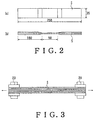
- Fig. 2 shows a configuration of test piece S.
- the dimension of the test piece S was 250 mm in length, 35 mm in width, about 1.6 mm in thickness when made of the fiber-reinforced resin layer part 3 only, and about 1.85 mm to about 1.95mm in thickness when the metal layer 1 is disposed therein.
- the SMA used as the metal layer 1 was obtained by the following steps.
- the SMA that is used as a metal layer 1 of the materials shown in Table 1 is cleaned with 3% hydrofluoric acid - 15% nitric acid to remove the oxide film on its surface formed during hot rolling process. After the surface of the SMA was roughened, the SMA was subjected to an anodic treatment by using 10% NaOH so as to generate a new oxide film. When the test piece S is formed, the surface of the SMA was completely cleaned with a solvent. Then, as shown in Fig. 3, the resin layer 2 and the fiber-reinforced resin layer part 3 were laminated by using a special jig 20 which can arrest a strain to be applied to the SMA. The test piece S was exposed to an environment of 180°C for 120 minutes so as to be molded and cured. Thereafter, a tab was attached to the test piece S, and the same was trimmed, so that the finished test piece S shown in Fig. 2 was obtained.
- test pieces S used in this test were as follows: only the fiber-reinforced resin layer part 3 (1 kind); the fiber-reinforced resin layer part 3 and the resin layer 2 (1 kind); the fiber-reinforced resin layer part 3, the resin layer 2, and the SMA (1 kind); and the fiber-reinforced resin layer part 3, the resin layer 2, and the SMA to which a 2% strain is imparted (2 kinds).
- the respective test pieces S were tested under environments at room temperature and at a temperature of 80°C. Thus, the tests were carried out under 10 conditions. Table 1 shows the lamination structures, board thicknesses, SMA volume ratios, and test temperatures of the test pieces S.
- test pieces S of A type as a comparative example were formed by laminating only the fiber-reinforced resin layer part 3.
- the test pieces S of A type included a test piece S of A1 type to be tested at room temperature and a test piece S of A2 type to be tested at a temperature of 80°C.
- Test pieces S of B type as a first example were formed by laminating the resin layer 2 between the adjacent fiber-reinforced resin layer parts 3.
- the test pieces S of B type inducted a test piece S of B1 type to be tested at room temperature and a test piece S of B2 type to be tested at a temperature of 80°C.
- Test pieces S of C type as a second embodiment were formed by laminating the metal layer 1 of 0.04 mm in thickness between the adjacent fiber-reinforced resin layer parts 3 through the resin layer 2.
- the test pieces S of C type included a test piece S of C1 type to be tested at room temperature and a test piece S of C2 type to be tested at a temperature of 80°C.
- Test pieces S of D type as a third example were formed by laminating the metal layer 1 of 0.04 mm in thickness to which a 2% strain had been previously imparted, between the adjacent fiber-reinforced resin layer parts 3 thorough the resin layer 2.
- test pieces S of D type included a test piece S of D1 type to be tested at room temperature and test piece S of D2 type to be tested at a temperature of 80°C.
- Test pieces S of E type were formed by laminating the metal layer 1 of 0.1 mm in thickness to which a 2% strain had been previously imparted, between the adjacent fiber-reinforced resin layer parts 3 through the resin layer 2.
- the test pieces S of E type included a test piece S of E1 type to be tested at room temperature and a test piece S of E2 type to be tested at a temperature of 80°C.
- a loading-unloading test was carried out by using the 10 kinds of test pieces S shown in Fig. 1.
- the respective test pieces S were set on a tension tester, and a predetermined strain is increasingly loaded from 0.2% to rupture at a loaded strain interval from 0.05% to 0.2%.
- a strain of each test piece S was measured by a dynamic strain meter based on an output from a strain gauge. Rupture of each test piece S was detected by using a liquid penetrant test.
- Figs. 4 and 5 show the test results. Based on the test result of A type test pieces, an effect on the resin layer 2 was examined by using the B type test pieces. An effect on the metal layer 1 formed by the SMA was examined by using the C type test pieces. An effect of the 2% strain of the SMA and an effect of restoring force thereof were examined by using the D type test pieces. A damage suppression effect and a recovering property were examined by using the E type test pieces in which the metal layer 1 has 2.5 times thickness.
- the test piece of D1 type had a 0.84% crack generation strain at room temperature. However, in the test piece of C2 type, the crack generation strain was improved up to 0.89% by heating.
- the test piece of E1 type had a 0.89% crack generation strain at room temperature. However, in the test piece of E2 type, the crack generation strain was improved up to 0.95% by heating.
- a transverse crack generation density was 8.1/cm in the test piece of A1 type, while it was 10.6/cm in the test piece of A2 type.
- a transverse crack generation density was 5.5/cm in the test piece of B1 type, which was about a 30% reduction relative to the test piece of A1 type, while it was 8.6/cm in the test piece of B2 type, which was about a 20% reduction relative to the test piece of A1 type.
- a transverse crack generation density was 5.7/cm, which was about a 30% reduction relative to the test piece of A1 type, while it was 7.3/cm in the test piece of C2 type, which was about a 30% reduction relative to the test piece of A1 type.
- a transverse crack generation density was 4.9/cm, which was about a 40% reduction relative to the test piece of A1 type, while it was 5.6/cm in the test piece of D2 type, which was about a 50% reduction relative to the test piece of A1 type.
- a transverse crack generation density was 1.15/cm, which was about an 86% reduction relative to the test piece of A1 type, while it was 4.55/cm in the test piece of E2 type, which was about a 57% reduction relative to the test piece of A1 type.
- a composite material having the resin layer 2 laminated on the fiber-reinforced resin layer part 3 has a lower transverse crack generation density than a composite material which is made only of the fiber-reinforced resin layer part 3. It is also found that, by laminating the resin layer 2 and the metal layer 1, a transverse crack generation density can be further decreased.
- a transverse crack generation density is more decreased in the latter.
- a delamination generation strain was 0.77% in the test piece of A1 type, while it was 0.83% in the test piece of A2 type.
- the delamination generation strain was significantly improved relative to the test piece of A1 type. That is, no delamination was generated in both the test pieces of B1 and B2 types when the strain exceeded 1.2%.
- the delamination generation strain is specified as 1.3%, as a matter of convenience.
- the delamination generation strain was lowered to 1% in the test piece of C1 type, it was 1 3% in the test piece of C2 type.
- the delamination generation strain was improved to 1.1% in the test piece of D1 type, and it was 1.3% in the test piece of D2 type.
- the delamination generation strain was 1.3% both in the test pieces of E1 and E2 types. Thus, no domination was generated at a loaded strain of 1.2%.
- the delamination generation strain is more improved in a composite material in which the resin layer 2 and the metal layer 1 are laminated than in a composite material which is made only of the fiber-reinforced resin layer part 3.
- the test pieces of C type in which no strain was imparted to the metal layer 1 with the test pieces of D type in which 2% strain was previously imparted to the metal layer 1, it is found that the delamination generation strain is more improved in the latter.
- the test pieces of D type in which the metal layer 1 has a thickness of 0.04 mm with the test pieces of E type in which the metal layer 1 has a thickness of 0.1 mm, it is found that the delamination generation strain is more improved in the latter.
- Fig. 6 shows a summary of the above results. Based on Fig. 6, it is found that the test pieces S of D type and the test pieces of E type have a higher damage suppression effect, each of which is made by the metal layer 1 formed of the SMA to which a strain is previously imparted, the resin layer 2, and the fiber-reinforced resin layer part 3. Of the two kinds of test pieces S having such a structure, the test pieces S of E type, in which a thickness of the SMA is 0.1 mm, is more preferable.
- test pieces S are compared with a conventional composite material 10 with reference to an observation by using a video scope.
- a transverse crack is generated at a loaded strain of 0.65%.
- the transverse crack passes vertically through the 90 degrees layer, and becomes a delamination.
- a loaded strain of 1.0% a clear delamination is observed.
- the transverse crack is generated at a loaded strain of 0.75%.
- the transverse crack passes vertically through the 90 degrees layer, and the delamination is generated at a loaded strain of 1.0%.
- the resin layer 2 not only contributes to improving the strength of the composite material 10, but also enhances an attachment between the metal layer 1 and the fiber-reinforced resin layer part 3. Therefore, the composite material 10 can be more firmly integrated, so that the strength thereof can be improved. As a result, as compared with a conventional composite material, a damage suppression effect can be increased.
- the metal layer 1 is formed of the SMA, when the metal layer 1 is heated to recover its original shape, the resin layer 2 and the fiber-reinforced resin layer part 3, which are laminated on the metal layer 1, are subjected to the recovering force of the metal layer 1 at the same time.
- the recovering force is applied to the resin layer 2 and the fiber-reinforced resin layer part 3.
- the external force is counterbalanced by the recovering force. Therefore, a critical stress at which a damage is generated in each layer can be enhanced.
- the fiber-reinforced resin layer part 3 is strengthened in four directions.
- a fiber-reinforced resin layer part 3 composed of four layers can provide a strength in the most uniform manner. That is, the fiber-reinforced resin layer part 3 is not strengthened in only a certain direction, so that a suitable structure of the composite material 10 is made possible.
- the fiber-reinforced resin layer part 3 is composed of four layers, it may be composed of six or eight layers. In the case of six layers, the first to sixth fiber-reinforced resin layers are respectively arranged at an angle of 30°. In the case of eight layers, the first to eighth fiber-reinforced resin layers are respectively arranged at an angle of 22.5 degrees.
- the SMA used as the metal layer 1 would recover by being heated. However, not limited thereto, the SMA may recover with a lapse of time. Other changes and modifications are possible without departing from the scope of the invention.
- a resin layer not only contributes to improving the strength of a composite material, but also enhances an attachment between a metal layer and a fiber-reinforced resin layer.
- the composite material can be more firmly integrated, so that the strength thereof can be improved. Therefore, an increased damage suppression effect of the composite material can be obtained relative to a conventional one.
Landscapes
- Laminated Bodies (AREA)
Abstract
Description
- The present invention relates to a fiber-reinforced composite material and a method of manufacturing the same. More particularly, it pertains to a fiber-reinforced composite material incorporating therein a shape-memory alloy to which a permanent strain is previously imparted.
- In recent years, a composite material used as a structural material for a future aircraft and high-speed vehicle has been consecutively developed, and a composite material of light weight and high strength has been proposed.
- For example, a composite material has been proposed (see, Japanese Patent Laid-Open Publication No. 2000-334888) in which a shape-memory alloy foil to which a strain is previously imparted at room temperature is buried in a CFRP (Carbon Fiber Reinforced Plastic) composite material laminate board, and the shape-memory alloy foil is electrified or heated from outside, so that a damaged region can be repaired by utilizing a shape recovery function of the shape-memory alloy foil as a damage suppression function.
- The composite material described in Japanese Patent Laid-Open Publication No. 2000-334888 includes the shape-memory alloy foil arranged between composite carbon fiber (hereinafter referred to as CFRP) layers, with the number of the CFRP layers being two. In such a composite material, a ratio of the volume of the shape-memory alloy foil with respect to the overall volume of the composite material is relatively high. In addition, the shape-memory alloy foil has a higher density than that of the CFRP. Thus, a further weight reduction of the composite material is inhibited.
- The present invention is made in view of the above disadvantage. An object of the present invention is to provide a composite material and a method of manufacturing the same, in which a weight of the composite material is reduced, while the strength thereof is improved to provide a higher damage suppression effect.
- In order to achieve the above object, a composite material, according to the first aspect of the present invention, comprises: a fiber-reinforced resin layer part including a plurality of fiber-reinforced resin layers in different fiber arrangement directions, the layers being laminated with each other; a metal layer made of a structural metal material, which is disposed between the fiber-reinforced resin layer parts; and a resin layer which attaches the metal layer and the fiber-reinforced resin layer part to each other.
- Herein, the structural metal material means a metal which has a strength sufficient for its use as a structural material of a structure. Since a required strength is varied according to a structure, a metal material to be used for a metal layer may also be changed.
- According to the first aspect of the present invention, the resin layer not only contributes to improving a damage generating strain of the composite material, but also enhances an attachment between the metal layer and the fiber-reinforced resin layer part. Therefore, the composite material can be more firmly integrated. As a result, as compared with a conventional composite material, a damage suppression effect can be increased.
- In a composite material according to the second aspect of the present invention, the metal layer may be made of a shape-memory alloy, and the resin layer and the fiber-reinforced resin layer part may be laminated on the metal layer to which a strain is previously imparted.
- According to the second aspect of the present invention, when the metal layer formed of a shape-memory alloy recovers its original shape, the resin layer and the fiber-reinforced resin layer part, which are laminated on the metal layer, are subjected to a recovering force of the metal layer at the same time. Thus, upon a recovery of the metal layer, the recovering force is applied to the resin layer and the fiber-reinforced resin layer part. In the case where an external force is applied in an opposite direction of the recovering force, the external force is counterbalanced by the recovering force. Therefore, a critical stress at which a damage is generated in each layer can be raised.
- In a composite material, according to the third aspect of the present invention, the fiber-reinforced resin layer part may be composed of n sheets of fiber-reinforced resin layers, and the fiber-reinforced resin layers may be laminated such that a minimum angle between the fiber-reinforced resin layers in a fiber arrangement direction is 180/n degrees.
- According to the third aspect of the present invention, the respective layers of the fiber-reinforced resin layer part are arranged at a uniform angle depending on the number of layers to be laminated. Thus, such a fiber-reinforced resin layer part can provide a strength in the most uniform manner. That is, fiber reinforced resin layer part is not strengthened in only a certain direction, so that a suitable structure of the composite material is made possible.
- In a composite material, according to the fourth aspect of the present invention, the fiber-reinforced resin layer part may include: a first fiber-feinforced resin layer in which fibers are arranged to extend perpendicular to a certain direction of the metal layer; a second fiber-reinforced resin layer laminated on the first fiber-reinforced resin layer, in which fibers are arranged to extend at an angle of -45 degrees relative to the certain direction of the metal layer; a third fiber-reinforced resin layer laminated on the second fiber-reinforced resin layer, in which fibers are arranged to extend along the certain direction of the metal layer; and a fourth fiber-reinforced resin layer laminated on the third fiber-reinforced resin layer, in which fibers are arranged to extend at an angle of 45 degrees relative to the certain direction of the metal layer.
- Herein, the certain direction means a direction in which load is mainly applied to the composite material.
- According to the fourth aspect of the present invention, since the first to fourth fiber-reinforced resin layers are respectively arranged at an angle of 45 degrees, the fiber-reinforced resin layer part is strengthened in four directions. Thus, such a fiber-reinforced resin layer part composed of four layers can provide a strength in the most uniform manner, That is, the fiber-reinforced resin layer part is not strengthened in only a certain direction, so that a suitable structure of the composite material is made possible.
- A method of manufacturing a composite material, according to the fifth aspect of the present invention, comprises the steps of: imparting a strain to a shape-memory alloy foil; laminating a resin layer on each surface of the shape-memory alloy foil; laminating a plurality of uncured fiber-reinforced resin layers on the resin layer; securing both ends of the shape-memory alloy foil to prevent a length of the foil from being changed; and heating the shape-memory alloy foil to cure the resin layer and the fiber-reinforced resin layers.
- According to the fifth aspect of the present invention, when the shape-memory alloy foil is heated to recover its original shape, the resin layer and the fiber-reinforced resin layers, which are laminated on the shape-memory alloy foil, are subjected to a recovering force of the shape-memory alloy foil at the same time. Thus, upon a recovery of the shape-memory alloy foil, the recovering force is applied to the resin layer and the fiber-reinforced resin layers. In the case where an external force is applied in an opposite direction of the recovering force, the external force is counterbalanced by the recovering force. Therefore, a critical stress at which a damage is generated in each layer can be raised. By way of example only, a specific embodiment of the present invention will now be described with reference to the accompanying drawings, in which:-
- Fig. 1 is a perspective view of a composite material according to the present invention;
- Fig. 2(a) is a plan view of a test piece;
- Fig. 2(b) is a side view of the test piece;
- Fig. 3 is a view illustrating a manufacture of the composite material;
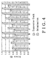
- Fig. 4 is a graph showing a comparison of damage properties of test pieces having different laminate structures;
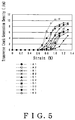
- Fig. 5 is a graph showing relationships of load strains and damage properties of test pieces having different laminate structures;
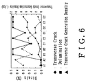
- Fig. 6 is a graph showing a comparison of damage properties of test pieces having different laminate structures;
- Fig. 7 is a view illustrating a process of generating a transverse crack and a delamination in a conventional composite material; and
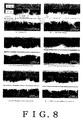
- Fig. 8 is a view illustrating a process of generating a transverse crack and a delamination in the composite material according to the present invention.
-
- An embodiment of a composite material and a method of manufacturing the same according to the present invention is described below in detail.
- As shown in Fig. 1, a
composite material 10 includes ametal layer 1 formed of a structural metal material, aresin layer 2 laminated on each surface of themetal layer 1, and a fiber-reinforcedresin layer part 3 having a plurality of fiber-reinforcedresin layers 31 to 34 which are laminated on theresin layer 2. - The
metal layer 1 is formed of a shape-memory alloy as a structural metal material. Herein, a Ti-50.2% Ni shape-memory alloy (hereinafter referred to as SMA) is used, for example. The SMA will recover to an original crystal structure by being heated. - The
resin layer 2 is interposed between themetal layer 1 and the fiber-reinforcedresin layer part 3. Theresin layer 2 improves an adhesive strength between themetal layer 1 and the fiber-reinforcedresin layer part 3, as well as enhancing the strength of thecomposite material 10. Herein, an epoxy-based resin adhesive film is used, for example. - The fiber-reinforced
resin layer part 3 includes the first fiber-reinforcedresin layer 31, the second fiber-reinforcedresin layer 32, the third fiber-reinforcedresin layer 33, and the fourth fiber-reinforcedresin layer 34. In the first fiber-reinforcedresin layer 31, fibers are arranged to extend perpendicular to a direction in which load is mainly applied to the metal layer 1 (a transverse direction to the plane of the drawing of Fig. 1). In the second fiber-reinforcedresin layer 32 laminated on the first fiber-reinforcedresin layer 31, fibers are arranged to extend at an angle of -45° relative to a direction in which load is mainly applied to themetal layer 1. In the third fiber-reinforcedresin layer 33 laminated on the second fiber-reinforcedresin layer 32, fibers are arranged to extend along a direction in which load is mainly applied to themetal layer 1. In the fourth fiber-reinforcedresin layer 34 laminated on the third fiber-reinforcedresin layer 33, fibers are arranged to extend at an angle of 45° relative to a direction in which load is mainly applied to themetal layer 1. Herein, carbon fibers can be used for forming each fiber-reinforced resin layer, for example. - The
composite material 10 and a method of manufacturing the same are described hereinbelow with reference to the examples. - In this test, two SMA foils 0.04 mm thick and 0.1 mm thick were used as the
metal layer 1. Fig. 2 shows a configuration of test piece S. The dimension of the test piece S was 250 mm in length, 35 mm in width, about 1.6 mm in thickness when made of the fiber-reinforcedresin layer part 3 only, and about 1.85 mm to about 1.95mm in thickness when themetal layer 1 is disposed therein. The SMA used as themetal layer 1 was obtained by the following steps. - In order to improve an adhesive property, the SMA that is used as a
metal layer 1 of the materials shown in Table 1, is cleaned with 3% hydrofluoric acid - 15% nitric acid to remove the oxide film on its surface formed during hot rolling process. After the surface of the SMA was roughened, the SMA was subjected to an anodic treatment by using 10% NaOH so as to generate a new oxide film. When the test piece S is formed, the surface of the SMA was completely cleaned with a solvent. Then, as shown in Fig. 3, theresin layer 2 and the fiber-reinforcedresin layer part 3 were laminated by using aspecial jig 20 which can arrest a strain to be applied to the SMA. The test piece S was exposed to an environment of 180°C for 120 minutes so as to be molded and cured. Thereafter, a tab was attached to the test piece S, and the same was trimmed, so that the finished test piece S shown in Fig. 2 was obtained. - The test pieces S used in this test were as follows: only the fiber-reinforced resin layer part 3 (1 kind); the fiber-reinforced
resin layer part 3 and the resin layer 2 (1 kind); the fiber-reinforcedresin layer part 3, theresin layer 2, and the SMA (1 kind); and the fiber-reinforcedresin layer part 3, theresin layer 2, and the SMA to which a 2% strain is imparted (2 kinds). The respective test pieces S were tested under environments at room temperature and at a temperature of 80°C. Thus, the tests were carried out under 10 conditions. Table 1 shows the lamination structures, board thicknesses, SMA volume ratios, and test temperatures of the test pieces S. - As shown in Table 1, test pieces S of A type as a comparative example were formed by laminating only the fiber-reinforced
resin layer part 3. The test pieces S of A type included a test piece S of A1 type to be tested at room temperature and a test piece S of A2 type to be tested at a temperature of 80°C. Test pieces S of B type as a first example were formed by laminating theresin layer 2 between the adjacent fiber-reinforcedresin layer parts 3. The test pieces S of B type inducted a test piece S of B1 type to be tested at room temperature and a test piece S of B2 type to be tested at a temperature of 80°C. Test pieces S of C type as a second embodiment were formed by laminating themetal layer 1 of 0.04 mm in thickness between the adjacent fiber-reinforcedresin layer parts 3 through theresin layer 2. The test pieces S of C type included a test piece S of C1 type to be tested at room temperature and a test piece S of C2 type to be tested at a temperature of 80°C. Test pieces S of D type as a third example were formed by laminating themetal layer 1 of 0.04 mm in thickness to which a 2% strain had been previously imparted, between the adjacent fiber-reinforcedresin layer parts 3 thorough theresin layer 2. The test pieces S of D type included a test piece S of D1 type to be tested at room temperature and test piece S of D2 type to be tested at a temperature of 80°C. Test pieces S of E type were formed by laminating themetal layer 1 of 0.1 mm in thickness to which a 2% strain had been previously imparted, between the adjacent fiber-reinforcedresin layer parts 3 through theresin layer 2. The test pieces S of E type included a test piece S of E1 type to be tested at room temperature and a test piece S of E2 type to be tested at a temperature of 80°C. - A loading-unloading test was carried out by using the 10 kinds of test pieces S shown in Fig. 1. The respective test pieces S were set on a tension tester, and a predetermined strain is increasingly loaded from 0.2% to rupture at a loaded strain interval from 0.05% to 0.2%. A strain of each test piece S was measured by a dynamic strain meter based on an output from a strain gauge. Rupture of each test piece S was detected by using a liquid penetrant test.

- Figs. 4 and 5 show the test results. Based on the test result of A type test pieces, an effect on the
resin layer 2 was examined by using the B type test pieces. An effect on themetal layer 1 formed by the SMA was examined by using the C type test pieces. An effect of the 2% strain of the SMA and an effect of restoring force thereof were examined by using the D type test pieces. A damage suppression effect and a recovering property were examined by using the E type test pieces in which themetal layer 1 has 2.5 times thickness. - As shown in Fig. 4, at a 0.67% strain, a transverse crack was generated in the first fiber-reinforced
resin layer 31 of the test piece of A1 type, while at a 0.65% strain, a transverse crack was generated in the test piece of A2 type. This difference shows a deterioration in the material property caused by heating. In the test pieces of B type, substantially the same results as those of the test pieces of A type were obtained, and no remarkable difference was found. The test piece of C1 type had a 0.7% crack generation strain at room temperature. However, in the test piece of C2 type, the crack generation strain was improved up to 0.75% by heating. It can be considered that such an effect was brought about due to an improvement in rigidity by an austenite transformation of the SMA. The test piece of D1 type had a 0.84% crack generation strain at room temperature. However, in the test piece of C2 type, the crack generation strain was improved up to 0.89% by heating. The test piece of E1 type had a 0.89% crack generation strain at room temperature. However, in the test piece of E2 type, the crack generation strain was improved up to 0.95% by heating. - Based on the above results, it is found that a provision of the
metal layer 1 formed of an SMA improves a transverse crack strain. - When comparing the test pieces of C type in which no strain was imparted to the
metal layer 1, with the test pieces of D type in which 2% strain was previously imparted to themetal layer 1, it is found that the transverse crack generation strain is more improved in the latter. When comparing the test pieces of D type in which themetal layer 1 has a thickness of 0.04 mm, with the test pieces of E type in which themetal layer 1 has a thickness of 0.1 mm, it is found that the transverse crack generation strain is more improved in the latter. - As shown in Fig. 5, with respect to the test pieces of A type at a loaded strain of 1.1%, a transverse crack generation density was 8.1/cm in the test piece of A1 type, while it was 10.6/cm in the test piece of A2 type. With respect to the test pieces of B type, a transverse crack generation density was 5.5/cm in the test piece of B1 type, which was about a 30% reduction relative to the test piece of A1 type, while it was 8.6/cm in the test piece of B2 type, which was about a 20% reduction relative to the test piece of A1 type. In the test piece of C1 type, a transverse crack generation density was 5.7/cm, which was about a 30% reduction relative to the test piece of A1 type, while it was 7.3/cm in the test piece of C2 type, which was about a 30% reduction relative to the test piece of A1 type. In the test piece of D1 type, a transverse crack generation density was 4.9/cm, which was about a 40% reduction relative to the test piece of A1 type, while it was 5.6/cm in the test piece of D2 type, which was about a 50% reduction relative to the test piece of A1 type. In the test piece of E1 type, a transverse crack generation density was 1.15/cm, which was about an 86% reduction relative to the test piece of A1 type, while it was 4.55/cm in the test piece of E2 type, which was about a 57% reduction relative to the test piece of A1 type.
- Based on the above results, it is found that a composite material having the
resin layer 2 laminated on the fiber-reinforcedresin layer part 3 has a lower transverse crack generation density than a composite material which is made only of the fiber-reinforcedresin layer part 3. It is also found that, by laminating theresin layer 2 and themetal layer 1, a transverse crack generation density can be further decreased. When comparing the test pieces of C type in which no strain was imparted to themetal layer 1, with the test pieces of D type in which 2% strain was previously imparted to themetal layer 1, it is found that a transverse crack generation density is more decreased in the latter. When comparing the test pieces of D type in which themetal layer 1 has a thickness of 0.04 mm, with the test pieces of E type in which themetal layer 1 has a thickness of 0.1 mm, it is found that the transverse crack generation density is lower in the latter. - As shown in Fig. 4, a delamination generation strain was 0.77% in the test piece of A1 type, while it was 0.83% in the test piece of A2 type. With respect to the test pieces of B type, the delamination generation strain was significantly improved relative to the test piece of A1 type. That is, no delamination was generated in both the test pieces of B1 and B2 types when the strain exceeded 1.2%. In Fig. 4, about the cases in which no delamination is generated at above 1.2% strain, the delamination generation strain is specified as 1.3%, as a matter of convenience. Although the delamination generation strain was lowered to 1% in the test piece of C1 type, it was 1 3% in the test piece of C2 type. The delamination generation strain was improved to 1.1% in the test piece of D1 type, and it was 1.3% in the test piece of D2 type. The delamination generation strain was 1.3% both in the test pieces of E1 and E2 types. Thus, no domination was generated at a loaded strain of 1.2%.
- Based on the above results, it is found that the delamination generation strain is more improved in a composite material in which the
resin layer 2 and themetal layer 1 are laminated than in a composite material which is made only of the fiber-reinforcedresin layer part 3. When comparing the test pieces of C type in which no strain was imparted to themetal layer 1, with the test pieces of D type in which 2% strain was previously imparted to themetal layer 1, it is found that the delamination generation strain is more improved in the latter. When comparing the test pieces of D type in which themetal layer 1 has a thickness of 0.04 mm, with the test pieces of E type in which themetal layer 1 has a thickness of 0.1 mm, it is found that the delamination generation strain is more improved in the latter. - Fig. 6 shows a summary of the above results. Based on Fig. 6, it is found that the test pieces S of D type and the test pieces of E type have a higher damage suppression effect, each of which is made by the
metal layer 1 formed of the SMA to which a strain is previously imparted, theresin layer 2, and the fiber-reinforcedresin layer part 3. Of the two kinds of test pieces S having such a structure, the test pieces S of E type, in which a thickness of the SMA is 0.1 mm, is more preferable. - The test pieces S are compared with a conventional
composite material 10 with reference to an observation by using a video scope. - As shown in Fig. 7, in the test pieces S of A type, a transverse crack is generated at a loaded strain of 0.65%. At a loaded strain of 0.8%, the transverse crack passes vertically through the 90 degrees layer, and becomes a delamination. At a loaded strain of 1.0%, a clear delamination is observed.
- On the other hand, as shown in Fig. 8, in the test pieces S of C type having the
metal layer 1, theresin layer 2, and the fiber-reinforcedresin layer part 3, the transverse crack is generated at a loaded strain of 0.75%. At a loaded strain of 0.9%, the transverse crack passes vertically through the 90 degrees layer, and the delamination is generated at a loaded strain of 1.0%. - Based on the above results, it is found that, as compared with the conventional composite material, damage can be significantly suppressed by laminating the
resin layer 2 and the fiber-reinforcedresin layer part 3 on themetal layer 1 formed of the SMA to which a strain is previously imparted, and heating themetal layer 1 to recover its original shape. - Thus, in the
composite material 10 and the method of manufacturing thecomposite material 10 according to the present embodiment, theresin layer 2 not only contributes to improving the strength of thecomposite material 10, but also enhances an attachment between themetal layer 1 and the fiber-reinforcedresin layer part 3. Therefore, thecomposite material 10 can be more firmly integrated, so that the strength thereof can be improved. As a result, as compared with a conventional composite material, a damage suppression effect can be increased. - Since the
metal layer 1 is formed of the SMA, when themetal layer 1 is heated to recover its original shape, theresin layer 2 and the fiber-reinforcedresin layer part 3, which are laminated on themetal layer 1, are subjected to the recovering force of themetal layer 1 at the same time. Thus, upon a recovery of themetal layer 1, the recovering force is applied to theresin layer 2 and the fiber-reinforcedresin layer part 3. In the case where an external force is applied in an opposite direction of the recovering force, the external force is counterbalanced by the recovering force. Therefore, a critical stress at which a damage is generated in each layer can be enhanced. - Since the first to fourth fiber-reinforced resin layers 31 to 34 are respectively arranged at an angle of 45 degrees, the fiber-reinforced
resin layer part 3 is strengthened in four directions. Thus, such a fiber-reinforcedresin layer part 3 composed of four layers can provide a strength in the most uniform manner. That is, the fiber-reinforcedresin layer part 3 is not strengthened in only a certain direction, so that a suitable structure of thecomposite material 10 is made possible. - The present invention is not limited to the above embodiment. For example, although the fiber-reinforced
resin layer part 3 is composed of four layers, it may be composed of six or eight layers. In the case of six layers, the first to sixth fiber-reinforced resin layers are respectively arranged at an angle of 30°. In the case of eight layers, the first to eighth fiber-reinforced resin layers are respectively arranged at an angle of 22.5 degrees. In this embodiment, the SMA used as themetal layer 1 would recover by being heated. However, not limited thereto, the SMA may recover with a lapse of time. Other changes and modifications are possible without departing from the scope of the invention. - That is, according to the present invention, a resin layer not only contributes to improving the strength of a composite material, but also enhances an attachment between a metal layer and a fiber-reinforced resin layer. Thus, the composite material can be more firmly integrated, so that the strength thereof can be improved. Therefore, an increased damage suppression effect of the composite material can be obtained relative to a conventional one.
- Further, the disclosure of Japanese Patent Application No. 57204/2003 filed on March 4, 2003 including the specification, drawings and abstract is incorporated by reference in its entirety.
Claims (8)
- A composite material comprisinga fiber-reinforced resin layer part including a plurality of fiber-reinforced resin layers in different fiber arrangement directions, the layers being laminated with each other;a metal layer made of a structural metal material, which is disposed between the fiber-reinforced resin layer parts; anda resin layer which attaches the metal layer and the fiber-reinforced resin layer part to each other.
- A composite material according to Claim 1, wherein
the metal layer is made of shape-memory alloy; and
the resin layer and the fiber-reinforced resin layer part are laminated on the metal layer to which a strain is previously imparted. - A composite material according to Claim 1, wherein
the fiber-reinforced resin layer part includes n sheets of fiber-reinforced resin layers; and
the fiber-reinforced resin layers are laminated such that a minimum angle between the fiber-reinforced resin layers in a fiber arrangement direction is 180/n degrees. - A composite material according to Claim 2, wherein
the fiber-reinforced resin layer part includes n sheets of fiber-reinforced resin layers; and
the fiber-reinforced resin layers are laminated such that a minimum angle between the fiber-reinforced resin layers in a fiber arrangement direction is 180/n degrees. - A composite material according to Claim 1, wherein the fiber-reinforced resin layer part includes:a first fiber-reinforced resin layer in which fibers are arranged to extend perpendicular to a certain direction of the metal layer;a second fiber-reinforced resin layer laminated on the first fiber-reinforced resin layer, in which fibers are arranged to extend at an angle of -45 degrees relative to a certain direction of the metal layer;a third fiber-reinforced resin layer laminated on the second fiber-reinforced resin layer, in which fibers are arranged to extend along a certain direction of the metal layer; anda fourth fiber-reinforced resin layer laminated on the third fiber-reinforced resin layer, in which fibers are arranged to extend at an angle of 45 degrees relative to a certain direction of the metal layer.
- A composite material according to Claim 2, wherein the fiber-reinforced resin layer part includes:a first fiber-reinforced resin layer in which fibers are arranged to extend perpendicular to a certain direction of the metal layer;a second fiber-reinforced resin layer laminated on the first fiber-reinforced resin layer, in which fibers are arranged to extend at an angle of -45 degrees relative to a certain direction of the metal layer;a third fiber-reinforced resin layer laminated on the second fiber-reinforced resin layer, in which fibers are arranged to extend along a certain direction of the metal layer; anda fourth fiber-reinforced resin layer laminated on the third fiber-reinforced resin layer, in which fibers are arranged to extend at an angle of 45 degrees relative to a certain direction of the metal layer.
- A composite material according to claim 3 or claim 4, wherein the fiber-reinforced resin layer part includes:a first fiber-reinforced resin layer in which libers are arranged to extend perpendicular to a certain direction of the metal layer;a second fiber-reinforced resin layer laminated on the first fiber-reinforced resin layer, in which fibers are arranged to extend at an angle of -45 degrees relative to a certain direction of the metal layer;a third fiber-reinforced resin layer laminated on the second fiber-reinforced resin layer, in which fibers are arranged to extend along a certain direction of the metal layer; anda fourth fiber-reinforced resin layer laminated on the third fiber-reinforced resin layer, in which fibers are arranged to extend at an angle of 45 degrees relative to a certain direction of the metal layer.
- A method of manufacturing a composite material which comprises:imparting a strain to a shape-memory alloy foil;laminating a resin layer on each surface of the shape-memory alloy foil;laminating a plurality of uncured fiber-reinforced resin layers on the resin layer;securing both ends of the shape-memory alloy foil to prevent a length of the foil from being changed; andheating the shape-memory alloy foil to cure the resin layer and the fiber-reinforced resin layers.
Applications Claiming Priority (2)
| Application Number | Priority Date | Filing Date | Title |
|---|---|---|---|
| JP2003057204A JP2004262191A (en) | 2003-03-04 | 2003-03-04 | Composite material and method for producing the same |
| JP2003057204 | 2003-03-04 |
Publications (2)
| Publication Number | Publication Date |
|---|---|
| EP1454737A1 true EP1454737A1 (en) | 2004-09-08 |
| EP1454737B1 EP1454737B1 (en) | 2007-09-05 |
Family
ID=32821179
Family Applications (1)
| Application Number | Title | Priority Date | Filing Date |
|---|---|---|---|
| EP20040251247 Expired - Lifetime EP1454737B1 (en) | 2003-03-04 | 2004-03-03 | Composite material and method of manufacturing the same |
Country Status (4)
| Country | Link |
|---|---|
| US (1) | US20040175555A1 (en) |
| EP (1) | EP1454737B1 (en) |
| JP (1) | JP2004262191A (en) |
| DE (1) | DE602004008685T2 (en) |
Cited By (3)
| Publication number | Priority date | Publication date | Assignee | Title |
|---|---|---|---|---|
| WO2007048426A1 (en) * | 2005-10-26 | 2007-05-03 | Tom Batot Frazier | Titanium barrier |
| CN103619578A (en) * | 2011-03-24 | 2014-03-05 | 蒂森克虏伯钢铁欧洲股份公司 | Composite material and structural component for a motor vehicle |
| CN103619578B (en) * | 2011-03-24 | 2016-11-30 | 蒂森克虏伯钢铁欧洲股份公司 | Composite and the structure member of automobile |
Families Citing this family (21)
| Publication number | Priority date | Publication date | Assignee | Title |
|---|---|---|---|---|
| GB0807593D0 (en) | 2008-04-28 | 2008-06-04 | Rolls Royce Plc | A composite article comprising a shape memory material member |
| KR100980635B1 (en) | 2008-08-07 | 2010-09-07 | 한국항공우주연구원 | Composite structure for vibration and shock reduction using shape memory alloy and manufacturing method |
| US8585856B1 (en) | 2010-05-13 | 2013-11-19 | Textron Innovations Inc. | Process for fabricating aircraft parts using an integrated form |
| US20110300358A1 (en) * | 2010-06-04 | 2011-12-08 | The Boeing Company | Shape memory alloy/fiber reinforced polymeric composite structures and method for forming |
| US9649820B1 (en) | 2012-02-08 | 2017-05-16 | Textron Innovations, Inc. | Assembly using skeleton structure |
| US9050757B1 (en) | 2012-02-08 | 2015-06-09 | Textron Innovations, Inc. | System and method for curing composites |
| US9302455B1 (en) | 2012-02-08 | 2016-04-05 | Textron Innovations, Inc. | Fast cure process |
| US9545757B1 (en) | 2012-02-08 | 2017-01-17 | Textron Innovations, Inc. | Composite lay up and method of forming |
| US9051062B1 (en) | 2012-02-08 | 2015-06-09 | Textron Innovations, Inc. | Assembly using skeleton structure |
| DE102012112965A1 (en) | 2012-12-21 | 2014-06-26 | Leibniz-Institut Für Neue Materialien Gemeinnützige Gesellschaft Mit Beschränkter Haftung | Object with switchable adhesion |
| US10464281B2 (en) | 2014-08-19 | 2019-11-05 | The Boeing Company | Sandwich composite with shape memory alloy core and method of making same |
| DE102014119470A1 (en) | 2014-12-22 | 2016-06-23 | Leibniz-Institut Für Neue Materialien Gemeinnützige Gmbh | Structured surface with gradual switchable adhesion |
| US10005267B1 (en) | 2015-09-22 | 2018-06-26 | Textron Innovations, Inc. | Formation of complex composite structures using laminate templates |
| WO2017125420A1 (en) * | 2016-01-22 | 2017-07-27 | Basf Se | Laminate, made up of a first layer of a first material and a second layer of a polymer reinforced with continuous fibres |
| CN108162538B (en) * | 2018-02-05 | 2023-12-15 | 江苏新光镭射包装材料股份有限公司 | Shape memory laser film and production method thereof |
| JP7248936B2 (en) * | 2018-06-08 | 2023-03-30 | 日本製鉄株式会社 | curved panel member |
| DE102018216935A1 (en) * | 2018-10-02 | 2020-04-02 | Thyssenkrupp Ag | Hybrid steel-plastic semi-finished product with shape memory properties |
| DE102018129384A1 (en) * | 2018-11-22 | 2020-05-28 | Fischerwerke Gmbh & Co. Kg | Fiber composite material |
| US11565505B2 (en) | 2019-09-10 | 2023-01-31 | General Electric Company | Laminate assembly with embedded conductive alloy elements |
| US11945205B2 (en) * | 2019-10-01 | 2024-04-02 | Nippon Steel Corporation | Curved panel part |
| US11731392B2 (en) * | 2019-10-01 | 2023-08-22 | Nippon Steel Corporation | Panel structure |
Citations (3)
| Publication number | Priority date | Publication date | Assignee | Title |
|---|---|---|---|---|
| US5614305A (en) * | 1995-02-08 | 1997-03-25 | Virginia Tech Intellectual Properties, Inc. | Impact and perforation resistant composite structures |
| JP2000334888A (en) * | 1999-05-28 | 2000-12-05 | Fuji Heavy Ind Ltd | Composite material and method of controlling damage to composite material |
| US6655218B1 (en) * | 1999-05-28 | 2003-12-02 | Fuji Jukogyo Kabushiki Kaisha | Composite material and method of controlling damage thereto and damage sensor |
-
2003
- 2003-03-04 JP JP2003057204A patent/JP2004262191A/en active Pending
-
2004
- 2004-03-03 US US10/790,802 patent/US20040175555A1/en not_active Abandoned
- 2004-03-03 DE DE200460008685 patent/DE602004008685T2/en not_active Expired - Fee Related
- 2004-03-03 EP EP20040251247 patent/EP1454737B1/en not_active Expired - Lifetime
Patent Citations (3)
| Publication number | Priority date | Publication date | Assignee | Title |
|---|---|---|---|---|
| US5614305A (en) * | 1995-02-08 | 1997-03-25 | Virginia Tech Intellectual Properties, Inc. | Impact and perforation resistant composite structures |
| JP2000334888A (en) * | 1999-05-28 | 2000-12-05 | Fuji Heavy Ind Ltd | Composite material and method of controlling damage to composite material |
| US6655218B1 (en) * | 1999-05-28 | 2003-12-02 | Fuji Jukogyo Kabushiki Kaisha | Composite material and method of controlling damage thereto and damage sensor |
Non-Patent Citations (2)
| Title |
|---|
| DATABASE WPI Section Ch Week 200113, Derwent World Patents Index; Class J04, AN 2001-115633, XP002287507 * |
| PATENT ABSTRACTS OF JAPAN vol. 2000, no. 15 6 April 2001 (2001-04-06) * |
Cited By (3)
| Publication number | Priority date | Publication date | Assignee | Title |
|---|---|---|---|---|
| WO2007048426A1 (en) * | 2005-10-26 | 2007-05-03 | Tom Batot Frazier | Titanium barrier |
| CN103619578A (en) * | 2011-03-24 | 2014-03-05 | 蒂森克虏伯钢铁欧洲股份公司 | Composite material and structural component for a motor vehicle |
| CN103619578B (en) * | 2011-03-24 | 2016-11-30 | 蒂森克虏伯钢铁欧洲股份公司 | Composite and the structure member of automobile |
Also Published As
| Publication number | Publication date |
|---|---|
| EP1454737B1 (en) | 2007-09-05 |
| JP2004262191A (en) | 2004-09-24 |
| DE602004008685D1 (en) | 2007-10-18 |
| DE602004008685T2 (en) | 2008-01-24 |
| US20040175555A1 (en) | 2004-09-09 |
Similar Documents
| Publication | Publication Date | Title |
|---|---|---|
| EP1454737B1 (en) | Composite material and method of manufacturing the same | |
| Li et al. | Mechanical performance and damage monitoring of CFRP thermoplastic laminates with an open hole repaired by 3D printed patches | |
| US6655218B1 (en) | Composite material and method of controlling damage thereto and damage sensor | |
| US4029838A (en) | Hybrid composite laminate structures | |
| US5227216A (en) | Fiber/metal laminate | |
| Tang et al. | A boundary layer theory-part II: extension of laminated finite strip | |
| EP0312150A1 (en) | Laminate of metal sheets and continuous filaments-reinforced thermoplastic synthetic material, as well as a process for the manufacture of such a laminate | |
| Hassan et al. | Investigation of the mechanical behavior of novel fiber metal laminates | |
| Ali et al. | Effect of the stacking sequence on the impact response of carbon-glass/epoxy hybrid composites | |
| CN110155303A (en) | For improving the laminated composite structures with interlayer corrugated part of shock resistance damage performance and forming the system and method for the structure | |
| Venkategowda et al. | Experimental Investigation of Glass-Carbon/Epoxy Hybrid Composites Subjected to Low Velocity Impact Test. | |
| Pankow et al. | Experimental investigation on the deformation response of hybrid 3D woven composites | |
| JP2003238698A (en) | Fiber-reinforced composite material, reinforcing fiber for fiber-reinforced composite material, and method for producing fiber-reinforced composite material | |
| JP2005161852A (en) | Metal / fiber reinforced plastic composite material and manufacturing method thereof | |
| Arzberger et al. | Elastic memory composite technology for thin lightweight space-and ground-based deployable mirrors | |
| US10125617B2 (en) | Composite structure and a method of fabricating the same | |
| Maikuma et al. | Bearing strength and damage progress for PAN-based and pitch-based carbon fiber composites | |
| Ogisu et al. | Improved surface treatment of SMA foils and damage suppression of SMA-foil embedded CFRP laminates | |
| Kochov et al. | Tensile strength of carbon fiber | |
| JP2010143155A (en) | Laminated composite material and method of manufacturing laminated composite material | |
| Hosseini-Toudeshky et al. | Effects of layups with negative and positive Poisson’s ratios on the stress–strain behaviors of plain and holed hybrid composite laminates | |
| Bruffey et al. | Predicting Flexural Strength of Composite Honeycomb Core Sandwich Panels Using Mechanical Models of Face Sheet Compressive Strength | |
| Colin de Verdiere et al. | Effect of tufting on the response of non crimp fabric composites. | |
| Ogisu et al. | Damage suppression in CFRP laminates using embedded shape memory alloy foils | |
| Watanabe et al. | New Solution for Material Damage Characterization of CFRP Laminate with Filament Winding Structure Using a Hexagonal-Shaped Mandrel |
Legal Events
| Date | Code | Title | Description |
|---|---|---|---|
| PUAI | Public reference made under article 153(3) epc to a published international application that has entered the european phase |
Free format text: ORIGINAL CODE: 0009012 |
|
| AK | Designated contracting states |
Kind code of ref document: A1 Designated state(s): AT BE BG CH CY CZ DE DK EE ES FI FR GB GR HU IE IT LI LU MC NL PL PT RO SE SI SK TR |
|
| AX | Request for extension of the european patent |
Extension state: AL HR LT LV MK |
|
| 17P | Request for examination filed |
Effective date: 20040903 |
|
| GRAP | Despatch of communication of intention to grant a patent |
Free format text: ORIGINAL CODE: EPIDOSNIGR1 |
|
| GRAS | Grant fee paid |
Free format text: ORIGINAL CODE: EPIDOSNIGR3 |
|
| AKX | Designation fees paid |
Designated state(s): DE FR GB |
|
| GRAA | (expected) grant |
Free format text: ORIGINAL CODE: 0009210 |
|
| AK | Designated contracting states |
Kind code of ref document: B1 Designated state(s): DE FR GB |
|
| REG | Reference to a national code |
Ref country code: GB Ref legal event code: FG4D |
|
| REF | Corresponds to: |
Ref document number: 602004008685 Country of ref document: DE Date of ref document: 20071018 Kind code of ref document: P |
|
| ET | Fr: translation filed | ||
| PGFP | Annual fee paid to national office [announced via postgrant information from national office to epo] |
Ref country code: GB Payment date: 20080227 Year of fee payment: 5 |
|
| PLBE | No opposition filed within time limit |
Free format text: ORIGINAL CODE: 0009261 |
|
| STAA | Information on the status of an ep patent application or granted ep patent |
Free format text: STATUS: NO OPPOSITION FILED WITHIN TIME LIMIT |
|
| PGFP | Annual fee paid to national office [announced via postgrant information from national office to epo] |
Ref country code: FR Payment date: 20080311 Year of fee payment: 5 Ref country code: DE Payment date: 20080228 Year of fee payment: 5 |
|
| 26N | No opposition filed |
Effective date: 20080606 |
|
| GBPC | Gb: european patent ceased through non-payment of renewal fee |
Effective date: 20090303 |
|
| REG | Reference to a national code |
Ref country code: FR Ref legal event code: ST Effective date: 20091130 |
|
| PG25 | Lapsed in a contracting state [announced via postgrant information from national office to epo] |
Ref country code: DE Free format text: LAPSE BECAUSE OF NON-PAYMENT OF DUE FEES Effective date: 20091001 |
|
| PG25 | Lapsed in a contracting state [announced via postgrant information from national office to epo] |
Ref country code: GB Free format text: LAPSE BECAUSE OF NON-PAYMENT OF DUE FEES Effective date: 20090303 Ref country code: FR Free format text: LAPSE BECAUSE OF NON-PAYMENT OF DUE FEES Effective date: 20091123 |