EP1454196B1 - Method and apparatus for a non-contact direct transfer imaging system - Google Patents
Method and apparatus for a non-contact direct transfer imaging system Download PDFInfo
- Publication number
- EP1454196B1 EP1454196B1 EP02783491A EP02783491A EP1454196B1 EP 1454196 B1 EP1454196 B1 EP 1454196B1 EP 02783491 A EP02783491 A EP 02783491A EP 02783491 A EP02783491 A EP 02783491A EP 1454196 B1 EP1454196 B1 EP 1454196B1
- Authority
- EP
- European Patent Office
- Prior art keywords
- developing
- photoreceptor
- toner
- imaging system
- charging
- Prior art date
- Legal status (The legal status is an assumption and is not a legal conclusion. Google has not performed a legal analysis and makes no representation as to the accuracy of the status listed.)
- Expired - Lifetime
Links
Images




Classifications
-
- G—PHYSICS
- G03—PHOTOGRAPHY; CINEMATOGRAPHY; ANALOGOUS TECHNIQUES USING WAVES OTHER THAN OPTICAL WAVES; ELECTROGRAPHY; HOLOGRAPHY
- G03G—ELECTROGRAPHY; ELECTROPHOTOGRAPHY; MAGNETOGRAPHY
- G03G15/00—Apparatus for electrographic processes using a charge pattern
- G03G15/01—Apparatus for electrographic processes using a charge pattern for producing multicoloured copies
- G03G15/0142—Structure of complete machines
- G03G15/0147—Structure of complete machines using a single reusable electrographic recording member
- G03G15/0152—Structure of complete machines using a single reusable electrographic recording member onto which the monocolour toner images are superposed before common transfer from the recording member
- G03G15/0157—Structure of complete machines using a single reusable electrographic recording member onto which the monocolour toner images are superposed before common transfer from the recording member with special treatment between monocolour image formation
-
- G—PHYSICS
- G03—PHOTOGRAPHY; CINEMATOGRAPHY; ANALOGOUS TECHNIQUES USING WAVES OTHER THAN OPTICAL WAVES; ELECTROGRAPHY; HOLOGRAPHY
- G03G—ELECTROGRAPHY; ELECTROPHOTOGRAPHY; MAGNETOGRAPHY
- G03G15/00—Apparatus for electrographic processes using a charge pattern
- G03G15/01—Apparatus for electrographic processes using a charge pattern for producing multicoloured copies
- G03G15/0142—Structure of complete machines
- G03G15/0147—Structure of complete machines using a single reusable electrographic recording member
- G03G15/0152—Structure of complete machines using a single reusable electrographic recording member onto which the monocolour toner images are superposed before common transfer from the recording member
- G03G15/0163—Structure of complete machines using a single reusable electrographic recording member onto which the monocolour toner images are superposed before common transfer from the recording member primary transfer to the final recording medium
Definitions
- the present invention relates generally to electrophotography, more particularly, to a non-contact developing system that utilizes only one image-receiving member that transfers images directly to media.
- Electrophotographic imaging process is a well-known method of copying or otherwise printing documents.
- electrophotographic imaging uses a charge-retentive, photosensitive surface (known as a photoreceptor) that is initially charged uniformly.
- the photoreceptor is then exposed to a light image representation of a desired image that discharges specific areas of the photoreceptor surface creating an electrostatic latent image.
- Toner powder is applied by using a developing system, which carries the toner from a toner container to the latent image, forming a developed image.
- This developed image is then transferred from the photoreceptor to a substrate (e.g. paper, transparency, and the like).
- a color electrophotographic imaging process is typically achieved by repeating the same process described above for each color of toner used and storing each developed color toner image to an accumulator until all desired colors are achieved and than transferred to a substrate (e.g. paper, transparency, and the like).
- United States Patent Specification No. US-A-5 640 230 discloses an electrostatic latent image developing method and an apparatus used in the latent image developing method.
- a bias supply voltage provided to a developing dish is gradually increased during a developing process so as to prevent a decrease in an effective bias voltage applied to the developing dish caused by the attachment of the toner to the developing dish.
- the electrostatic latent image is formed on a photosensitive member by scanning a laser beam on a preliminarily charged photosensitive member in a lateral scanning direction.
- the latent image thereby formed is developed by absorbing a toner in a liquid developer in a developing dish, wherein a cleaning pattern image having a large toner absorbability for absorbing the toner attached to a surface of the developing dish is provided on the photosensitive member by the laser beam before and/or after the latent image is formed on the photosensitive member.
- US 6 188 860 discloses an electrostatic image forming arrangement including a photoreceptor in the form of a continuous belt which is moved past four development stations, each containing a different colored toner which incorporates ferromagnetic material.
- a developer roller conveys toner in closely spaced relation to the surface of the photoreceptor and a DC-biased AC voltage is applied to the developer roller to cause the toner to be transferred to an electrostatic image on the photoreceptor.
- a magnet member mounted on the opposite side of the photoreceptor produces a magnetic filed which holds toner on the image-receiving surface permitting a greater range of variation for the DC-biased AC toner transfer voltage.
- the present invention is directed to a non-contact developing system for electrophotographic machines that effectively reduces the cost and complexity of typical color electrophotographic imaging systems at the same time enabling the ability to directly transfer a developed image to a substrate (e.g. paper, transparency, and the like) without the use of an accumulating means.
- a substrate e.g. paper, transparency, and the like
- the developing system of the present invention reduces the need for redundant charging and exposing means by preparing the subsequent developing station for a desired condition or response before the first developed toner carried by the photoreceptor passes. More particularly, when subsequent developing is not required the subsequent developing station is prepared for a desired condition by cleaning a toner support member of the developing station of any toner before the first developed toner or latent image passes to ensure contamination of colors or partial development does not occur.
- the method of preparing the subsequent developing stations for a desired condition enables the first developed image to pass through the subsequent developing station and be carried by the photoreceptor to the next available charging and exposing means.
- the first developed toner and the photoreceptor is prepared for an additional developed toner by the next available charging and exposing means it is returned to desired color station where an additional color is developed. This process is repeated until the desired colors are achieved and than transferred to a substrate (e.g. paper, transparency, and the like).
- a substrate e.g. paper, transparency, and the like.
- an electrophotographic imaging system 100 includes four developing units 10, 20, 30, 40, two charging units 80, 81 and two exposure elements 70, 71.
- a cleaning station 50 is also utilized in the system.
- the electrophotographic imaging system 100 also includes a flexible, transparent photoreceptor belt 90 with an outer surface 92 and an inner surface 94.
- the photoreceptor belt 90 is driven in a continuous path in a direction indicated by arrow A at a velocity ⁇ by a plurality of rollers 96a, 96b and 96c.
- Each of the developing units 10, 20, 30, 40 contain a different colored developer, for example Y, M, C and K, and are disposed in opposing relationship with the photoreceptor 90 with a gap therebetween defining a developing region.
- Each of the developing units 10, 20, 30, 40 has a respective toner support member, such as a developing roller 12, 22, 32, 42 shown in FIG. 3A .
- Each toner support member is adapted to carry a toner thereon to the developing region, thus producing a differently colored image, in superimposed relation, without mechanical devices applying the developer because such contact would disturb previously produced differently colored image.
- the electrophotographic imaging system of the present invention is a multicolor, multipass imaging system, not all of the four developing stations 10, 20, 30, 40 have their development function turned “on” and operating during any one of the required number of passes, for a particular differently colored image. The remaining developing stations are cleaned and therefore have their development functions turned “off.”
- each developing station 10, 20, 30, 40 has a respective developing roller 12, 22, 32, 42.
- Developing rollers 12, 22, 32, 42 are kept in a non-contact state against the photoreceptor belt 90 with a predetermined spacing.
- a developing bias voltage composed of a direct current voltage or an alternate current voltage of a magnitude ranging from -700 volts to -900 volts is applied to the respective developing roller 12, 22, 32, 42 so that non-contact development process can be achieved.
- the developing roller is not rotated. Accordingly, a finite and limited amount of toner 14, 24, 34, 44 is available for transfer to the photoreceptor belt 90.
- toner from the "off" developing station can be removed using a "cleaning patch” 75 which is created by charging the photoreceptor belt 90 to an appropriate level and time to attract toner from the developing station. That is, the developing station is “cleaned” by passing the cleaning patch 75 across the path of the developing station that requires cleaning thus causing the toner from the developing station to attract and develop to the cleaning patch 75 on the photoreceptor belt 90. The cleaning station 50 then cleans the cleaning patch 75 at the end of the pass.
- the two charging units 80, 81 are also disposed on the outer surface of the photoreceptor belt 90.
- the charging units 80, 81 can be an AC or DC corotron, scorotron, dicorotron, a discorotron, a pin scorotron or any other device capable of setting up a uniform electric field on the order of -700 volts magnitude on the photoreceptor belt 90. It should be understood that the actual charge placed on the photoreceptor belt 90 for the first toner (and the other toner layers that are subsequently described) will depend upon many variables, such as toner mass and the settings of a subsequent development station (see below).
- Charging unit 80 is located upstream from developing stations 10 and 20, while charging unit 81 is located upstream from developing stations 30 and 40.
- each charging unit 80, 81 Located downstream from each charging unit 80, 81 is a light source 70, 71, for example a laser or a light-emitting diode (“LED”) printer head (“LPH”).
- the light sources are disposed at or near the inner surface 94 of the photoreceptor belt 90.
- the light sources 70, 71 include exposure units such as LEDs that are selectively actuated to project light corresponding to a single-color image on the photoreceptor belt 90, thereby discharging, at appropriate locations on the outer surface 92, the uniform electrostatic charge provided by the charging units 80, 81 to produce an electrostatic charge latent image 77 as shown in Fig. 3B .
- illuminationd sections of the latent image area might be discharged by the light beam to about -50 volts in magnatude.
- the light sources 70 and 71 are independently capable of discharging the photoreceptor belt at appropriate locations, levels and times to create "cleaning patch" 75 on the belt 90. As with the latent imaging area, cleaning patch 75 has been created by uniformly charging the photoreceptor by means of the charging units 80 and 81 and then discharging the photoreceptor by means of the light sources 70 and 71.
- a given developing station is upstream of another developing station if, in a given pass, the imaging arca passes the given developing station before it passes the second developing station. Conversely, a given developing station is downstream of a second, if in a given pass, the imaging area passes the given developing station after it passes the second developing station.
- a four-toner subtractive color image requires only two passes of the photoreceptor.
- the photoreceptor i.e., a portion of photoreceptor belt 90
- the two exposure laments expose the photoreceptor with the pattern for the last two colors.
- the substrate e.g., paper
- the present invention cleans those developing stations not being used in each pass using a cleaning patch.
- Toner accumulated on the cleaning patch is removed as the patch passes cleaning station 50.
- the cleaning station 50 can be any conventional system known to those skilled in the art.
- the cleaning station may include a rotatably mounted fibrous brush in contact with photoconductive belt 90 to disturb and remove paper fibers and a cleaning blade to remove the nontransferred toner particles.
- the blade may be configured in either a wiper or doctor position depending on the application.
- developing stations 20 and 40 remain “off” while developing stations 10 and 30 are turned “on” at specified times. These times may be determined by an appropriate algorithm and controlled by a microprocessor (not shown).
- charging unit 80 charges the photoreceptor belt 90 to a uniform charge between -700 volts to -900 volts.
- the light source 70 imposes a cleaning patch 75 on the photoreceptor belt 90 by discharging the belt 90 to about -50 volts.
- the light source 70 As the photoreceptor belt 90 moves, at time t 2 , the light source 70 then imposes a latent image 77 (shown in FIG. 3B ) on the photoreceptor belt 90 by discharging the belt.
- the latent image 77 is preferably formed a distance L from the cleaning patch 75 such that the distance L is equal to the distance between the developing station 10 and the developing station 20.
- FIG. 3E shows that as the latent image area 77 passes a developing station 10, charged toner particles 14 are deposited onto the image area.
- the charged toner particles 14 adhere to the illuminated areas of the image area thereby causing the voltage of the illuminated parts of the image area to be about -250 volts.
- the non-illuminated parts of the image area remain at a voltage of -700.
- toner 24 having a voltage of about -200 volts is attracted to the cleaning patch, thereby cleaning the developing station 20 of toner 24.
- FIG. 3E further shows that as the latent image 77 approaches the developing station 20, little or no toner 24 remains on the developing station 20 to contaminate the latent image 77. In addition, because the developing station 20 is not grounded, the toner 14 on the latent image does not contaminate the developing station 20.
- the second charging unit 81 recharges cleaning patch 75 and the area of latent image 77 to the charge level desired for exposure and development of the next color image.
- the recharged cleaning patch 75 and image area 77 with its first toner layer then advances to the light source 71.
- the now exposed cleaning patch 75 advances past another development station 30, incidentally cleaning it, and approaches developing station 40 (which is "off') to remove the toner from developing station 40.
- the latent image created by light source 71 attracts toner from developing station 30. Since the image area 77 already has a first toner layer produced at developing station 10, the developing station 30 should use a scavengeless developer. Because developing station 40 has been cleaned by the cleaning patch, there is no contamination as the latent image moves by that developing station.
- the toner on the cleaning patch 75 is the cleaned by the cleaning station 50.
- the second cycle then begins.
- developing stations 10 and 30 are "off" while developing stations 20 and 40 are turned on at specified times. Again, these times may be determined by an appropriate algorithm and controlled by a microprocessor.
- the charging units 80 and 81 can be arranged to be independently capable of charging the photoreceptor belt at appropriate locations, levels and times to create a "cleaning patch" on the belt 90.
- the charging units 80 and 81 can vary in voltage levels and times in creating a uniform electric field on the order of - 700 volts magnitude on the photoreceptor belt 90 and in creating a uniform electric field on the order of -50 volts magnitude on the photoreceptor belt 90 thus creating a cleaning patch by means of charging the photoreceptor belt 90 with variant voltage magnitudes. While various embodiments of the application have been described, it will be apparent to those of ordinary skill in the art that many more embodiments and implementations are possible that are within the scope of this invention. Accordingly, the invention is not to be restricted except in light of the attached claims and their equivalents.
Landscapes
- Physics & Mathematics (AREA)
- General Physics & Mathematics (AREA)
- Color Electrophotography (AREA)
- Cleaning In Electrography (AREA)
- Electrostatic Charge, Transfer And Separation In Electrography (AREA)
- Studio Devices (AREA)
- Controlling Rewinding, Feeding, Winding, Or Abnormalities Of Webs (AREA)
- Pipeline Systems (AREA)
- Photoreceptors In Electrophotography (AREA)
- Two-Way Televisions, Distribution Of Moving Picture Or The Like (AREA)
- Closed-Circuit Television Systems (AREA)
- Sorting Of Articles (AREA)
- Discharging, Photosensitive Material Shape In Electrophotography (AREA)
- Developing For Electrophotography (AREA)
Abstract
Description
- The present invention relates generally to electrophotography, more particularly, to a non-contact developing system that utilizes only one image-receiving member that transfers images directly to media.
- Electrophotographic imaging process (or xerography) is a well-known method of copying or otherwise printing documents. In general, electrophotographic imaging uses a charge-retentive, photosensitive surface (known as a photoreceptor) that is initially charged uniformly. The photoreceptor is then exposed to a light image representation of a desired image that discharges specific areas of the photoreceptor surface creating an electrostatic latent image. Toner powder is applied by using a developing system, which carries the toner from a toner container to the latent image, forming a developed image. This developed image is then transferred from the photoreceptor to a substrate (e.g. paper, transparency, and the like).
- A color electrophotographic imaging process is typically achieved by repeating the same process described above for each color of toner used and storing each developed color toner image to an accumulator until all desired colors are achieved and than transferred to a substrate (e.g. paper, transparency, and the like).
United States Patent Specification No.US-A-5 640 230 discloses an electrostatic latent image developing method and an apparatus used in the latent image developing method. In a first image developing method, a bias supply voltage provided to a developing dish is gradually increased during a developing process so as to prevent a decrease in an effective bias voltage applied to the developing dish caused by the attachment of the toner to the developing dish. In a second disclosed developing method, the electrostatic latent image is formed on a photosensitive member by scanning a laser beam on a preliminarily charged photosensitive member in a lateral scanning direction. The latent image thereby formed is developed by absorbing a toner in a liquid developer in a developing dish, wherein a cleaning pattern image having a large toner absorbability for absorbing the toner attached to a surface of the developing dish is provided on the photosensitive member by the laser beam before and/or after the latent image is formed on the photosensitive member.
United States Patent Specification No.US 6 188 860 discloses an electrostatic image forming arrangement including a photoreceptor in the form of a continuous belt which is moved past four development stations, each containing a different colored toner which incorporates ferromagnetic material. At each development station, a developer roller conveys toner in closely spaced relation to the surface of the photoreceptor and a DC-biased AC voltage is applied to the developer roller to cause the toner to be transferred to an electrostatic image on the photoreceptor. A magnet member mounted on the opposite side of the photoreceptor produces a magnetic filed which holds toner on the image-receiving surface permitting a greater range of variation for the DC-biased AC toner transfer voltage. - Previous attempts of producing an imaging system without the use of an accumulator have used redundant charging and exposing systems to prepare the developed toner for passing through each coloring stations yellow, magenta, cyan and black without being disturbed by the subsequent developing process. More specifically, each developing station requires an exposing and a charging means to enable the developing process to occur before entering the next developing station. Although adequate imaging can be achieved by using this process, the cost and complexity of the machine is significantly increased due to the need of additional exposing and charging means.
- The present invention is directed to a non-contact developing system for electrophotographic machines that effectively reduces the cost and complexity of typical color electrophotographic imaging systems at the same time enabling the ability to directly transfer a developed image to a substrate (e.g. paper, transparency, and the like) without the use of an accumulating means.
- In a particularly innovative aspect, the developing system of the present invention reduces the need for redundant charging and exposing means by preparing the subsequent developing station for a desired condition or response before the first developed toner carried by the photoreceptor passes. More particularly, when subsequent developing is not required the subsequent developing station is prepared for a desired condition by cleaning a toner support member of the developing station of any toner before the first developed toner or latent image passes to ensure contamination of colors or partial development does not occur. The method of preparing the subsequent developing stations for a desired condition enables the first developed image to pass through the subsequent developing station and be carried by the photoreceptor to the next available charging and exposing means. Once the first developed toner and the photoreceptor is prepared for an additional developed toner by the next available charging and exposing means it is returned to desired color station where an additional color is developed. This process is repeated until the desired colors are achieved and than transferred to a substrate (e.g. paper, transparency, and the like).
- In the figures, like reference numerals designate corresponding parts throughout the different views. The invention may take physical form in certain parts of which will be described in detail in this specification and illustrated in the accompanying drawings, which form a part hereof, wherein:
-
Figures 1A-1C are schematics illustrating the operation of an imaging system in accordance with the prior art; -
Figure 2 is a schematic illustrating an imaging system, which employs the present invention; and -
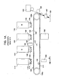
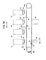
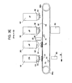
Figures 3A-3E are schematics illustrating an exemplary operation of the imaging system inFigure 1 in accordance with the present invention. - In the representative embodiment of the invention shown in
FIG. 2 , an electrophotographic imaging system 100 includes four developingunits charging units exposure elements cleaning station 50 is also utilized in the system. The electrophotographic imaging system 100 also includes a flexible,transparent photoreceptor belt 90 with anouter surface 92 and aninner surface 94. Thephotoreceptor belt 90 is driven in a continuous path in a direction indicated by arrow A at a velocity ν by a plurality ofrollers - Each of the developing
units photoreceptor 90 with a gap therebetween defining a developing region. Each of the developingunits roller FIG. 3A . Each toner support member is adapted to carry a toner thereon to the developing region, thus producing a differently colored image, in superimposed relation, without mechanical devices applying the developer because such contact would disturb previously produced differently colored image. - Since the electrophotographic imaging system of the present invention is a multicolor, multipass imaging system, not all of the four developing
stations - As shown in
figure 3 , each developingstation roller rollers photoreceptor belt 90 with a predetermined spacing. At the time of the developing process by the developingstation roller toner photoreceptor belt 90. As discussed below, toner from the "off" developing station can be removed using a "cleaning patch" 75 which is created by charging thephotoreceptor belt 90 to an appropriate level and time to attract toner from the developing station. That is, the developing station is "cleaned" by passing thecleaning patch 75 across the path of the developing station that requires cleaning thus causing the toner from the developing station to attract and develop to thecleaning patch 75 on thephotoreceptor belt 90. Thecleaning station 50 then cleans thecleaning patch 75 at the end of the pass. - In this embodiment, the two
charging units photoreceptor belt 90. Thecharging units photoreceptor belt 90. It should be understood that the actual charge placed on thephotoreceptor belt 90 for the first toner (and the other toner layers that are subsequently described) will depend upon many variables, such as toner mass and the settings of a subsequent development station (see below). Chargingunit 80 is located upstream from developingstations unit 81 is located upstream from developingstations - Located downstream from each
charging unit light source inner surface 94 of thephotoreceptor belt 90. Thelight sources photoreceptor belt 90, thereby discharging, at appropriate locations on theouter surface 92, the uniform electrostatic charge provided by thecharging units latent image 77 as shown inFig. 3B . For example, illuminated sections of the latent image area might be discharged by the light beam to about -50 volts in magnatude. - The
light sources belt 90. As with the latent imaging area,cleaning patch 75 has been created by uniformly charging the photoreceptor by means of thecharging units light sources - During operation and movement of the
cleaning patch 75 and thelatent image 77, two relative directions are defined: upstream and downstream. For example, a given developing station is upstream of another developing station if, in a given pass, the imaging arca passes the given developing station before it passes the second developing station. Conversely, a given developing station is downstream of a second, if in a given pass, the imaging area passes the given developing station after it passes the second developing station. - Operation of exemplary imaging system of the present invention will now be described in reference to
FIGs. 3A-3E . In general, because the present invention employs twophotoreceptor charging units exposure elements 70, 71 (rather than four), a four-toner subtractive color image requires only two passes of the photoreceptor. During the first pass, the photoreceptor (i.e., a portion of photoreceptor belt 90) is exposed with the pattern for two colors, which are developed. During the second pass, the two exposure laments expose the photoreceptor with the pattern for the last two colors. Then, the substrate (e.g., paper) is brought into operable relation to the photoreceptor and the four-color image is transferred and later fused. - Rather than ground the developing
stations station 50. The cleaningstation 50 can be any conventional system known to those skilled in the art. The cleaning station may include a rotatably mounted fibrous brush in contact withphotoconductive belt 90 to disturb and remove paper fibers and a cleaning blade to remove the nontransferred toner particles. The blade may be configured in either a wiper or doctor position depending on the application. - During the first pass in one implementation, developing
stations stations unit 80 charges thephotoreceptor belt 90 to a uniform charge between -700 volts to -900 volts. As shown inFIG. 3A , at time t1, thelight source 70 imposes acleaning patch 75 on thephotoreceptor belt 90 by discharging thebelt 90 to about -50 volts. As thephotoreceptor belt 90 moves, at time t2, thelight source 70 then imposes a latent image 77 (shown inFIG. 3B ) on thephotoreceptor belt 90 by discharging the belt. Thelatent image 77 is preferably formed a distance L from thecleaning patch 75 such that the distance L is equal to the distance between the developingstation 10 and the developingstation 20. - As the
photoreceptor belt 90 moves, at time t3 (shown inFIG. 3C ) thecleaning patch 75approaches developing station 10 which is "off" (i.e., not rotating). The cleaning patch therefore incidentally removes sometoner 14 from the developingstation 10. Once thecleaning patch 75passes developing station 10 at time t4 (shown inFIG. 3D ), developingstation 10 is turned "on." Then, at time t5 (shown inFIG. 3E ), thelatent image 77approaches developing station 10, while the cleaning patch approaches developingstation 20 which is "off" (not rotating). -
FIG. 3E shows that as thelatent image area 77 passes a developingstation 10, chargedtoner particles 14 are deposited onto the image area. The chargedtoner particles 14 adhere to the illuminated areas of the image area thereby causing the voltage of the illuminated parts of the image area to be about -250 volts. The non-illuminated parts of the image area remain at a voltage of -700. As thecleaning patch 75passes developing station 20,toner 24 having a voltage of about -200 volts is attracted to the cleaning patch, thereby cleaning the developingstation 20 oftoner 24. -
FIG. 3E further shows that as thelatent image 77 approaches the developingstation 20, little or notoner 24 remains on the developingstation 20 to contaminate thelatent image 77. In addition, because the developingstation 20 is not grounded, thetoner 14 on the latent image does not contaminate the developingstation 20. - A similar process is repeated for developing
stations second charging unit 81recharges cleaning patch 75 and the area oflatent image 77 to the charge level desired for exposure and development of the next color image. The rechargedcleaning patch 75 andimage area 77 with its first toner layer then advances to thelight source 71. After passing the exposure station, the now exposed cleaningpatch 75 advances past anotherdevelopment station 30, incidentally cleaning it, and approaches developing station 40 (which is "off') to remove the toner from developingstation 40. The latent image created bylight source 71 attracts toner from developingstation 30. Since theimage area 77 already has a first toner layer produced at developingstation 10, the developingstation 30 should use a scavengeless developer. Because developingstation 40 has been cleaned by the cleaning patch, there is no contamination as the latent image moves by that developing station. The toner on thecleaning patch 75 is the cleaned by the cleaningstation 50. - The second cycle then begins. In this implementation for the second cycle, developing
stations stations units belt 90. More specifically, the chargingunits photoreceptor belt 90 and in creating a uniform electric field on the order of -50 volts magnitude on thephotoreceptor belt 90 thus creating a cleaning patch by means of charging thephotoreceptor belt 90 with variant voltage magnitudes.
While various embodiments of the application have been described, it will be apparent to those of ordinary skill in the art that many more embodiments and implementations are possible that are within the scope of this invention. Accordingly, the invention is not to be restricted except in light of the attached claims and their equivalents.
Claims (6)
- A method of preparing an imaging system (100) to produce color images utilizing at least one charging unit, the method comprising the steps of:providing a plurality of developing stations (10, 20, 30, 40) capable of developing a color image to a photoreceptor (90) of the imaging system (100), wherein the developing stations are disposed in opposing relationship with the photoreceptor (90) with a gap therebetween;creating a cleaning patch (75) by charging and then discharging a portion (75) of the photoreceptor (90) to a predetermined level; andcleaning a toner support member (12, 22, 32, 42) of the imaging system by using the cleaning patch (75), the toner support member being in an "off"-state wherein the development function is turned off and the toner support member is not rotated when the cleaning patch approaches the toner support member andremoving toner from the cleaning patch (75) to a toner waste station associated with the imaging system.
- The method of claim 1, wherein two charging means (80, 81) and two exposing means (70, 71) are used for charging and discharging a portion (75) of the photoreceptor.
- The method of claim 1, comprising operating at least one charging means configured to transfer a charge to the photoreceptor that is more positive than the voltage contained in the developing stations.
- The method of claim 3, wherein the at least one charging means is operably configured to transfer a charge to the photoreceptor (90) that greater than or equal to -700 volts.
- The method of claim 1, wherein the photoreceptor is a photoreceptor belt (90).
- The method of claim 1, wherein at least one of the plurality of developing stations is operably configured to contain a voltage ranging from -700 volts to -900 volts.
Applications Claiming Priority (3)
| Application Number | Priority Date | Filing Date | Title |
|---|---|---|---|
| US17434 | 1979-03-05 | ||
| US10/017,434 US6687473B2 (en) | 2001-12-14 | 2001-12-14 | Method and apparatus for a non-contact direct transfer imaging system |
| PCT/IE2002/000170 WO2003052523A1 (en) | 2001-12-14 | 2002-12-16 | Method and apparatus for a non-contact direct transfer imaging system |
Publications (2)
| Publication Number | Publication Date |
|---|---|
| EP1454196A1 EP1454196A1 (en) | 2004-09-08 |
| EP1454196B1 true EP1454196B1 (en) | 2008-05-14 |
Family
ID=21782561
Family Applications (1)
| Application Number | Title | Priority Date | Filing Date |
|---|---|---|---|
| EP02783491A Expired - Lifetime EP1454196B1 (en) | 2001-12-14 | 2002-12-16 | Method and apparatus for a non-contact direct transfer imaging system |
Country Status (9)
| Country | Link |
|---|---|
| US (1) | US6687473B2 (en) |
| EP (1) | EP1454196B1 (en) |
| JP (1) | JP2004038134A (en) |
| CN (1) | CN1424630B (en) |
| AT (1) | ATE395634T1 (en) |
| AU (1) | AU2002347564A1 (en) |
| DE (1) | DE60226633D1 (en) |
| TW (1) | TWI223737B (en) |
| WO (1) | WO2003052523A1 (en) |
Families Citing this family (3)
| Publication number | Priority date | Publication date | Assignee | Title |
|---|---|---|---|---|
| US6889021B2 (en) * | 2002-09-26 | 2005-05-03 | Aetes Technology Inc. | Electrophotograpic printing apparatus including a photoreceptor belt having a defined shape |
| US7260341B2 (en) * | 2006-01-23 | 2007-08-21 | Aetus System Incorporated | Cleaning patch for an image forming apparatus |
| JP5235432B2 (en) * | 2008-01-30 | 2013-07-10 | キヤノン株式会社 | Image forming apparatus |
Family Cites Families (6)
| Publication number | Priority date | Publication date | Assignee | Title |
|---|---|---|---|---|
| JP2938543B2 (en) * | 1990-10-05 | 1999-08-23 | 株式会社リコー | Image forming device |
| JPH0635378A (en) * | 1992-07-21 | 1994-02-10 | Konica Corp | Image forming device |
| JP3013877B2 (en) * | 1995-02-01 | 2000-02-28 | 日本ビクター株式会社 | Method and apparatus for developing electrostatic latent image |
| US5713064A (en) * | 1996-01-17 | 1998-01-27 | Eastman Kodak Company | Method and apparatus for forming toner images with two distinct toners |
| US5903797A (en) * | 1997-08-15 | 1999-05-11 | Xerox Corporation | Monitoring cleaning performance to predict cleaner life |
| US6188860B1 (en) * | 1999-06-18 | 2001-02-13 | Aetas Technology Corporation | Method and arrangement for developing a plurality of electrostatic images on a substrate |
-
2001
- 2001-12-14 US US10/017,434 patent/US6687473B2/en not_active Expired - Fee Related
-
2002
- 2002-10-16 TW TW091123865A patent/TWI223737B/en not_active IP Right Cessation
- 2002-12-13 JP JP2002363138A patent/JP2004038134A/en active Pending
- 2002-12-13 CN CN02156168.0A patent/CN1424630B/en not_active Expired - Fee Related
- 2002-12-16 EP EP02783491A patent/EP1454196B1/en not_active Expired - Lifetime
- 2002-12-16 WO PCT/IE2002/000170 patent/WO2003052523A1/en not_active Ceased
- 2002-12-16 AU AU2002347564A patent/AU2002347564A1/en not_active Abandoned
- 2002-12-16 AT AT02783491T patent/ATE395634T1/en not_active IP Right Cessation
- 2002-12-16 DE DE60226633T patent/DE60226633D1/en not_active Expired - Lifetime
Also Published As
| Publication number | Publication date |
|---|---|
| CN1424630A (en) | 2003-06-18 |
| CN1424630B (en) | 2010-05-26 |
| EP1454196A1 (en) | 2004-09-08 |
| DE60226633D1 (en) | 2008-06-26 |
| WO2003052523A1 (en) | 2003-06-26 |
| ATE395634T1 (en) | 2008-05-15 |
| TWI223737B (en) | 2004-11-11 |
| US6687473B2 (en) | 2004-02-03 |
| JP2004038134A (en) | 2004-02-05 |
| AU2002347564A1 (en) | 2003-06-30 |
| US20030113136A1 (en) | 2003-06-19 |
Similar Documents
| Publication | Publication Date | Title |
|---|---|---|
| EP0375432B1 (en) | Method and apparatus for creating images | |
| US5282012A (en) | Color electronic photographic apparatus with multiple image forming units | |
| EP0492452B1 (en) | Process for coloring an electrostatic image | |
| EP0747778B1 (en) | Method of producing a color image | |
| CA2044319C (en) | Highlight printing apparatus | |
| US5220386A (en) | Image forming apparatus having cleanable transfer material carrying means | |
| US4984021A (en) | Photoreceptor edge erase system for tri-level xerography | |
| US5303009A (en) | Image forming apparatus with an improved discharger | |
| JP2005114975A (en) | Image forming apparatus | |
| US6687473B2 (en) | Method and apparatus for a non-contact direct transfer imaging system | |
| EP0601787B1 (en) | Colour imaging by rendering selectiv colours visible in single pass colour process | |
| JP2876902B2 (en) | Color electrophotographic equipment | |
| EP0361851B1 (en) | Photoreceptor edge erase system especially for tri-level xerography | |
| US5115280A (en) | Residual toner cleaning apparatus for color image forming device | |
| EP0735433B1 (en) | Penta-level xerographic unit | |
| EP0892316B1 (en) | Colour printing machine | |
| US5480751A (en) | Tri-level background suppression scheme using an AC scorotron with front erase | |
| EP1111476B1 (en) | Control system for printing machine | |
| US5404205A (en) | Image forming apparatus with an improved cleaning means | |
| JPH07306561A (en) | Tandem engine type color image forming device | |
| CA2258070C (en) | Reverse polarity split recharge in recharge-expose-and-develop image on imaging printing | |
| EP0886192B1 (en) | Colour printing machine | |
| JP2002251046A (en) | Image forming device | |
| JPH07120997A (en) | Color image forming device | |
| JPH0375668A (en) | Developing device |
Legal Events
| Date | Code | Title | Description |
|---|---|---|---|
| PUAI | Public reference made under article 153(3) epc to a published international application that has entered the european phase |
Free format text: ORIGINAL CODE: 0009012 |
|
| 17P | Request for examination filed |
Effective date: 20040701 |
|
| AK | Designated contracting states |
Kind code of ref document: A1 Designated state(s): AT BE BG CH CY CZ DE DK EE ES FI FR GB GR IE IT LI LU MC NL PT SE SI SK TR |
|
| AX | Request for extension of the european patent |
Extension state: AL LT LV MK RO |
|
| RIN1 | Information on inventor provided before grant (corrected) |
Inventor name: TSAI, TAN-FENG,8F.-1, NO.370, DUENHUA RD. Inventor name: LIN, CHOU-JIUNG,NO.7, ALLEY 7, LANE 400 Inventor name: MU, TAOMO,5F, NO. 7 LI-HSIN ROAD V, Inventor name: HU, JON-SHIN Inventor name: LEE, VINCENT,NO.3, ALLEY 8, LANE 122 Inventor name: WANG, BOB |
|
| 17Q | First examination report despatched |
Effective date: 20061128 |
|
| 17Q | First examination report despatched |
Effective date: 20061128 |
|
| 17Q | First examination report despatched |
Effective date: 20061128 |
|
| GRAP | Despatch of communication of intention to grant a patent |
Free format text: ORIGINAL CODE: EPIDOSNIGR1 |
|
| GRAS | Grant fee paid |
Free format text: ORIGINAL CODE: EPIDOSNIGR3 |
|
| GRAA | (expected) grant |
Free format text: ORIGINAL CODE: 0009210 |
|
| AK | Designated contracting states |
Kind code of ref document: B1 Designated state(s): AT BE BG CH CY CZ DE DK EE ES FI FR GB GR IE IT LI LU MC NL PT SE SI SK TR |
|
| REG | Reference to a national code |
Ref country code: GB Ref legal event code: FG4D |
|
| REG | Reference to a national code |
Ref country code: CH Ref legal event code: EP |
|
| REG | Reference to a national code |
Ref country code: IE Ref legal event code: FG4D Free format text: LANGUAGE OF EP DOCUMENT: FRENCH |
|
| REF | Corresponds to: |
Ref document number: 60226633 Country of ref document: DE Date of ref document: 20080626 Kind code of ref document: P |
|
| PG25 | Lapsed in a contracting state [announced via postgrant information from national office to epo] |
Ref country code: SI Free format text: LAPSE BECAUSE OF FAILURE TO SUBMIT A TRANSLATION OF THE DESCRIPTION OR TO PAY THE FEE WITHIN THE PRESCRIBED TIME-LIMIT Effective date: 20080514 |
|
| PG25 | Lapsed in a contracting state [announced via postgrant information from national office to epo] |
Ref country code: FI Free format text: LAPSE BECAUSE OF FAILURE TO SUBMIT A TRANSLATION OF THE DESCRIPTION OR TO PAY THE FEE WITHIN THE PRESCRIBED TIME-LIMIT Effective date: 20080514 Ref country code: ES Free format text: LAPSE BECAUSE OF FAILURE TO SUBMIT A TRANSLATION OF THE DESCRIPTION OR TO PAY THE FEE WITHIN THE PRESCRIBED TIME-LIMIT Effective date: 20080825 |
|
| NLV1 | Nl: lapsed or annulled due to failure to fulfill the requirements of art. 29p and 29m of the patents act | ||
| PG25 | Lapsed in a contracting state [announced via postgrant information from national office to epo] |
Ref country code: NL Free format text: LAPSE BECAUSE OF FAILURE TO SUBMIT A TRANSLATION OF THE DESCRIPTION OR TO PAY THE FEE WITHIN THE PRESCRIBED TIME-LIMIT Effective date: 20080514 Ref country code: AT Free format text: LAPSE BECAUSE OF FAILURE TO SUBMIT A TRANSLATION OF THE DESCRIPTION OR TO PAY THE FEE WITHIN THE PRESCRIBED TIME-LIMIT Effective date: 20080514 |
|
| PG25 | Lapsed in a contracting state [announced via postgrant information from national office to epo] |
Ref country code: DK Free format text: LAPSE BECAUSE OF FAILURE TO SUBMIT A TRANSLATION OF THE DESCRIPTION OR TO PAY THE FEE WITHIN THE PRESCRIBED TIME-LIMIT Effective date: 20080514 Ref country code: PT Free format text: LAPSE BECAUSE OF FAILURE TO SUBMIT A TRANSLATION OF THE DESCRIPTION OR TO PAY THE FEE WITHIN THE PRESCRIBED TIME-LIMIT Effective date: 20081014 Ref country code: CZ Free format text: LAPSE BECAUSE OF FAILURE TO SUBMIT A TRANSLATION OF THE DESCRIPTION OR TO PAY THE FEE WITHIN THE PRESCRIBED TIME-LIMIT Effective date: 20080514 Ref country code: SE Free format text: LAPSE BECAUSE OF FAILURE TO SUBMIT A TRANSLATION OF THE DESCRIPTION OR TO PAY THE FEE WITHIN THE PRESCRIBED TIME-LIMIT Effective date: 20080814 |
|
| PG25 | Lapsed in a contracting state [announced via postgrant information from national office to epo] |
Ref country code: BE Free format text: LAPSE BECAUSE OF FAILURE TO SUBMIT A TRANSLATION OF THE DESCRIPTION OR TO PAY THE FEE WITHIN THE PRESCRIBED TIME-LIMIT Effective date: 20080514 Ref country code: SK Free format text: LAPSE BECAUSE OF FAILURE TO SUBMIT A TRANSLATION OF THE DESCRIPTION OR TO PAY THE FEE WITHIN THE PRESCRIBED TIME-LIMIT Effective date: 20080514 |
|
| PLBE | No opposition filed within time limit |
Free format text: ORIGINAL CODE: 0009261 |
|
| STAA | Information on the status of an ep patent application or granted ep patent |
Free format text: STATUS: NO OPPOSITION FILED WITHIN TIME LIMIT |
|
| 26N | No opposition filed |
Effective date: 20090217 |
|
| PG25 | Lapsed in a contracting state [announced via postgrant information from national office to epo] |
Ref country code: BG Free format text: LAPSE BECAUSE OF FAILURE TO SUBMIT A TRANSLATION OF THE DESCRIPTION OR TO PAY THE FEE WITHIN THE PRESCRIBED TIME-LIMIT Effective date: 20080814 Ref country code: EE Free format text: LAPSE BECAUSE OF FAILURE TO SUBMIT A TRANSLATION OF THE DESCRIPTION OR TO PAY THE FEE WITHIN THE PRESCRIBED TIME-LIMIT Effective date: 20080514 |
|
| PG25 | Lapsed in a contracting state [announced via postgrant information from national office to epo] |
Ref country code: MC Free format text: LAPSE BECAUSE OF NON-PAYMENT OF DUE FEES Effective date: 20081231 |
|
| REG | Reference to a national code |
Ref country code: CH Ref legal event code: PL |
|
| PG25 | Lapsed in a contracting state [announced via postgrant information from national office to epo] |
Ref country code: IT Free format text: LAPSE BECAUSE OF FAILURE TO SUBMIT A TRANSLATION OF THE DESCRIPTION OR TO PAY THE FEE WITHIN THE PRESCRIBED TIME-LIMIT Effective date: 20080514 |
|
| PG25 | Lapsed in a contracting state [announced via postgrant information from national office to epo] |
Ref country code: IE Free format text: LAPSE BECAUSE OF NON-PAYMENT OF DUE FEES Effective date: 20081216 Ref country code: CH Free format text: LAPSE BECAUSE OF NON-PAYMENT OF DUE FEES Effective date: 20081231 Ref country code: LI Free format text: LAPSE BECAUSE OF NON-PAYMENT OF DUE FEES Effective date: 20081231 |
|
| PG25 | Lapsed in a contracting state [announced via postgrant information from national office to epo] |
Ref country code: LU Free format text: LAPSE BECAUSE OF NON-PAYMENT OF DUE FEES Effective date: 20081216 Ref country code: CY Free format text: LAPSE BECAUSE OF FAILURE TO SUBMIT A TRANSLATION OF THE DESCRIPTION OR TO PAY THE FEE WITHIN THE PRESCRIBED TIME-LIMIT Effective date: 20080514 |
|
| PG25 | Lapsed in a contracting state [announced via postgrant information from national office to epo] |
Ref country code: TR Free format text: LAPSE BECAUSE OF FAILURE TO SUBMIT A TRANSLATION OF THE DESCRIPTION OR TO PAY THE FEE WITHIN THE PRESCRIBED TIME-LIMIT Effective date: 20080514 |
|
| PG25 | Lapsed in a contracting state [announced via postgrant information from national office to epo] |
Ref country code: GR Free format text: LAPSE BECAUSE OF FAILURE TO SUBMIT A TRANSLATION OF THE DESCRIPTION OR TO PAY THE FEE WITHIN THE PRESCRIBED TIME-LIMIT Effective date: 20080815 |
|
| PGFP | Annual fee paid to national office [announced via postgrant information from national office to epo] |
Ref country code: GB Payment date: 20141218 Year of fee payment: 13 |
|
| PGFP | Annual fee paid to national office [announced via postgrant information from national office to epo] |
Ref country code: DE Payment date: 20141230 Year of fee payment: 13 |
|
| PGFP | Annual fee paid to national office [announced via postgrant information from national office to epo] |
Ref country code: FR Payment date: 20141224 Year of fee payment: 13 |
|
| REG | Reference to a national code |
Ref country code: DE Ref legal event code: R119 Ref document number: 60226633 Country of ref document: DE |
|
| GBPC | Gb: european patent ceased through non-payment of renewal fee |
Effective date: 20151216 |
|
| REG | Reference to a national code |
Ref country code: FR Ref legal event code: ST Effective date: 20160831 |
|
| PG25 | Lapsed in a contracting state [announced via postgrant information from national office to epo] |
Ref country code: GB Free format text: LAPSE BECAUSE OF NON-PAYMENT OF DUE FEES Effective date: 20151216 Ref country code: DE Free format text: LAPSE BECAUSE OF NON-PAYMENT OF DUE FEES Effective date: 20160701 |
|
| PG25 | Lapsed in a contracting state [announced via postgrant information from national office to epo] |
Ref country code: FR Free format text: LAPSE BECAUSE OF NON-PAYMENT OF DUE FEES Effective date: 20151231 |