EP1454176B1 - Cover slip - Google Patents
Cover slip Download PDFInfo
- Publication number
- EP1454176B1 EP1454176B1 EP02794211A EP02794211A EP1454176B1 EP 1454176 B1 EP1454176 B1 EP 1454176B1 EP 02794211 A EP02794211 A EP 02794211A EP 02794211 A EP02794211 A EP 02794211A EP 1454176 B1 EP1454176 B1 EP 1454176B1
- Authority
- EP
- European Patent Office
- Prior art keywords
- spacer
- cover slip
- substrate
- channels
- chamber
- Prior art date
- Legal status (The legal status is an assumption and is not a legal conclusion. Google has not performed a legal analysis and makes no representation as to the accuracy of the status listed.)
- Expired - Lifetime
Links
Images



Classifications
-
- B—PERFORMING OPERATIONS; TRANSPORTING
- B01—PHYSICAL OR CHEMICAL PROCESSES OR APPARATUS IN GENERAL
- B01L—CHEMICAL OR PHYSICAL LABORATORY APPARATUS FOR GENERAL USE
- B01L3/00—Containers or dishes for laboratory use, e.g. laboratory glassware; Droppers
- B01L3/50—Containers for the purpose of retaining a material to be analysed, e.g. test tubes
- B01L3/508—Rigid containers without fluid transport within
-
- G—PHYSICS
- G02—OPTICS
- G02B—OPTICAL ELEMENTS, SYSTEMS OR APPARATUS
- G02B21/00—Microscopes
- G02B21/34—Microscope slides, e.g. mounting specimens on microscope slides
-
- B—PERFORMING OPERATIONS; TRANSPORTING
- B01—PHYSICAL OR CHEMICAL PROCESSES OR APPARATUS IN GENERAL
- B01L—CHEMICAL OR PHYSICAL LABORATORY APPARATUS FOR GENERAL USE
- B01L2200/00—Solutions for specific problems relating to chemical or physical laboratory apparatus
- B01L2200/06—Fluid handling related problems
- B01L2200/0684—Venting, avoiding backpressure, avoid gas bubbles
-
- B—PERFORMING OPERATIONS; TRANSPORTING
- B01—PHYSICAL OR CHEMICAL PROCESSES OR APPARATUS IN GENERAL
- B01L—CHEMICAL OR PHYSICAL LABORATORY APPARATUS FOR GENERAL USE
- B01L2300/00—Additional constructional details
- B01L2300/08—Geometry, shape and general structure
- B01L2300/0809—Geometry, shape and general structure rectangular shaped
- B01L2300/0822—Slides
-
- B—PERFORMING OPERATIONS; TRANSPORTING
- B01—PHYSICAL OR CHEMICAL PROCESSES OR APPARATUS IN GENERAL
- B01L—CHEMICAL OR PHYSICAL LABORATORY APPARATUS FOR GENERAL USE
- B01L2400/00—Moving or stopping fluids
- B01L2400/04—Moving fluids with specific forces or mechanical means
- B01L2400/0403—Moving fluids with specific forces or mechanical means specific forces
- B01L2400/0406—Moving fluids with specific forces or mechanical means specific forces capillary forces
-
- Y—GENERAL TAGGING OF NEW TECHNOLOGICAL DEVELOPMENTS; GENERAL TAGGING OF CROSS-SECTIONAL TECHNOLOGIES SPANNING OVER SEVERAL SECTIONS OF THE IPC; TECHNICAL SUBJECTS COVERED BY FORMER USPC CROSS-REFERENCE ART COLLECTIONS [XRACs] AND DIGESTS
- Y10—TECHNICAL SUBJECTS COVERED BY FORMER USPC
- Y10T—TECHNICAL SUBJECTS COVERED BY FORMER US CLASSIFICATION
- Y10T436/00—Chemistry: analytical and immunological testing
- Y10T436/25—Chemistry: analytical and immunological testing including sample preparation
Definitions
- This invention relates to a cover slip of the type used to contain a specimen on a substrate for use in a hybridization reaction or similar molecular search.
- Complementarity is the sequence-specific or shaped-specific molecular recognition that occurs when two molecules bind together. Complementary between a probe molecule and a target molecule can result in the formation of a probe-target complex. This complex can then be located if the probe molecules are tagged with a detectible entity such as a chromophore, fluorophore, radioactivity, or an enzyme.
- a detectible entity such as a chromophore, fluorophore, radioactivity, or an enzyme.
- a single-stranded DNA (ssDNA) probe molecule can form a double-stranded, base pair hybrid with an ssDNA target if the probe sequence is the reverse complement of the target sequence.
- An ssDNA probe molecule can form a double-stranded, base-paired hybrid with an RNA target if the probe sequence is the reverse complement of the target sequence.
- An antibody probe molecule can form a complex with a target protein molecule if the antibody's antigen-binding site can bind to an epitope on the target protein.
- microarray (or DNA chip) based hybridization uses various probes which enable the simultaneous analysis of thousands of sequences of DNA for genetic and genomic research and for diagnosis.
- Most DNA microarray fabrications employ a similar experimental approach.
- the probe DNA with a defined identity is immobilized onto a solid medium.
- the probe is then allowed to hybridize with solutions of nucleic acid sequences, or conjugates, that contain a detectable label.
- the signal is then detected and analyzed. Variations of this approach are available for RNA-DNA and protein-protein hybridizations and those hybridization techniques involving tissue sections that are immobilized on a substrate. In all of these protocols, the hybridization solution is placed directly on the substrate that contains the immobilized DNA or tissue section.
- the hybridization reaction is performed in a warm environment, and one problem is that the hybridization solution may evaporate resulting in inadvertent contamination of the solution that is on the substrate.
- a cover slip is placed directly on the solution. The weight of the cover slip, however, can displace the solution and minimize the volume of the solution that is in contact with the immobilized component. Therefore, a portion of the immobilized component may have an insufficient amount or no hybridization solution covering it.
- the cover slip In an attempt to reduce the displacement of the cover slip, it is known to print ink as bars on two opposed edges of the cover slip.
- the ink structures raise the cover slip above the substrate thus providing a chamber and a larger volume or space for the hybridization solutions.
- the cover slip is often made from a #2 cover glass that has a nominal thickness of about 0.2 millimeters ("mm").
- mm millimeters
- a nominal thickness of 0.2 mm means that, if measured, the cover glass thickness may vary in a range of about 0.17-0.25 mm.
- the dimensional range of cover glass also varies with the supplier; and thus, a variation in the measured dimension from the nominal dimension is to be expected.
- a cover glass that is 0.2 mm thick is thin and flexible.
- the cover slip is readily flexed or bent by the application of a very small force.
- a center portion of the cover slip between the printed ink bars can be warped or pulled toward the substrate.
- the hybridization solution is displaced resulting in an unequal dispersion of the components in the solution over the immobilized component.
- the cover slip in filling the space between the coverslip and the substrate with hybridization solution, the cover slip can be warped or pushed outward. Pushing the cover slip outward increases the volume of the chamber.
- the very thin cover slip can unpredictably warp or bend due to forces inherent within the structure of the glass or from forces generated by the printing and curing of the ink bars on the cover slip.
- any bending, deflecting or warping of the cover slip results in different distances between the cover slip and the substrate; and that warping and bending of the cover slip can cause substantial variations in the size of the chamber between the cover slip and the substrate.
- One disadvantage of varying spacing between the cover slip and the substrate is that different amounts of hybridization solution are dispersed to different areas over the immobilized component, thereby producing a less consistent hybridization reaction and less consistent hybridization results.
- Another disadvantage of varying spacing between the cover slip and the substrate is that greater volumes of hybridization solutions will be used. Using more than the minimum necessary adds unnecessary cost to the hybridization reaction. It has been found that with the opposed printed bars on the cover slip, evaporation of the hybridization solution continues to be a problem.
- a cover slip for use with a substrate that provides more consistent results from a hybridization reaction or similar molecular search, uses a consistent and minimum amount of hybridization solution or other liquid, and further reduces evaporation.
- the present invention provides a cover slip that substantially improves the quality of a hybridization reaction or similar molecular search with which it is used.
- the cover slip of the present invention provides uniform dispersion of components of a hybridization solution throughout a chamber formed between the cover slip and a substrate, thereby improving the consistency and quality of the hybridization reaction.
- the cover slip of the present invention further permits the volume of the chamber between the cover slip and the substrate to be minimized without adversely affecting the uniformity of the dispersion of the hybridization solution.
- the cover slip of the present invention the quantity of hybridization solution used is minimized; and the cost of the hybridization reaction is reduced.
- the improved process quality is repeatable from one cover slip/substrate combination to another.
- the present invention provides an apparatus of the type used to contain a liquid over a specimen on a substrate for the purpose of performing a hybridization or other molecular complementation reaction, comprising a spacer having a first pair of spacer segments adapted to contact the substrate and a cover slip having a lower surface and two substantially parallel, opposed longitudinal edges bounding the lower surface, each of the first pair of spacer segments extending along a substantial length of a different one of the opposed longitudinal edges and forming a chamber between the spacer segments, the lower surface of the cover slip and the substrate, the chamber adapted to contain the specimen when the cover slip is placed on the substrate with the spacer sandwiched therebetween, characterized in that the cover slip has a thickness of at least 1.0 mm to provide a cover slip beam stiffness sufficient to react adhesion forces resulting from liquid being introduced between the cover slip and the substrate to maintain a substantially constant distance between the lower surface and the substrate when the liquid is introduced between the cover slip and the substrate.
- the spacer extends along the perimeter of the cover slip and has discontinuities forming two channels across the perimeter for introducing the liquid therethrough.
- the spacer determines a distance between the cover slip and the substrate. By extending along most of the perimeter of the cover slip, the spacer substantially reduces evaporation of the liquid.
- the discontinuities form four channels across the perimeter at corners of the cover slip.
- the invention also provides a method of preparing a reaction chamber of the type used to contain a liquid over a specimen on a substrate for the purpose of performing a hybridization or other molecular complementation reaction comprising providing a substrate having a specimen on a surface thereof, providing a cover slip having a perimeter with a spacer, placing the cover slip with the spacer on the surface of the substrate with the spacer sandwiched therebetween to form a chamber between the cover slip and the substrate and around the specimen, the spacer extending over a substantial length of the perimeter, characterized in that the step of providing a cover slip with a spacer comprises affixing a spacer to a cover slip which has a thickness of at least 1.0 mm; in that the method further comprises introducing the liquid into the chamber via capillary action, and maintaining a substantially constant distance between the cover slip and the substrate throughout the chamber by reacting adhesion forces of the liquid in the chamber with the cover slip by the use of the cover slip with a thickness of at least 1.0 mm.
- a cover slip/substrate combination 20 is comprised of a cover slip 22 and a support or substrate 24.
- the substrate 24 may be any material suitable for the reaction being conducted, for example, a DNA chip, microarray, a glass slide, such as a 25x75 mm microscope slide, or any other type of suitable support.
- a microscope slide has a thickness of about 1.016 mm.
- the cover slip 22 is illustrated as being smaller in width than the substrate 24, for example, about 22 mm. However, in the embodiment of Fig. 1 , the cover slip 22 may have even a smaller width, the same width or a larger width than the substrate 24.
- the length of the cover slip 22 may be any size; and as will be appreciated, the length and width of the cover slip 22 will depend on their application and the equipment and practices of a user.
- Affixed to the cover slip 22 are an opposed pair of spacer bars 26, 28 extending substantially the full length of respective longitudinal edges 30, 32.
- a reservoir or chamber 34 is formed between a cover slip lower surface 36 and a substrate upper surface 38.
- the chamber 34 often contains an immobilized material 42, for example, a tissue sample, DNA or other hybridizable material. Other hybridizable materials include isolated RNA and protein, and human, animal and plant tissue sections containing DNA, RNA, and protein that are used for research and diagnostic purposes.
- the chamber 34 also contains a liquid 44, for example, a liquid hybridization solution. Cover slips used in such hybridization reactions are relatively thin, that is, the thickness is in a range of about 0.17-0.25 mm. As discussed, such a thin cover slip unpredictably warps or bends during use end from one cover slip to another.
- the cover slip 22 is thicker than known cover slips used with hybridization reactions.
- the cover slip 22 can be made from commercially available glass that is used to make microscope slides and that has a nominal thickness of about 1.0 mm. Higher quality microscope slide glass that has a flatness of about ⁇ 0.005 mm provides a more uniform spacing between the cover slip and the substrate. An even thicker cover glass can be used, for example, a glass having a thickness of 2.0 mm or more.
- a desired thickness is a function of the price of the glass, case and cost of handling and cutting the glass, as well as the applications and equipment of a a customer, for example, a thinner cover slip and substrate combination will fit in more hybrid chambers, Therefore, a cover glass made from a higher quality microscope slide glass having a thickness of about 1.0 mm will probably be most often used.
- the thicker cover slip 22 is rigid and inflexible and has an inherent beam stiffness that keeps it from warping and bending during either the heat curing process or its use. With a substantially flat lower surface 36, a substantially constant chamber height 40 is mainlined between the confronting surfaces 36, 38. Thus, with the thicker cover slip 22, the spacer bars 26, 28 now effectively function to exclusively control the chamber height 40 and hence, the volume of the chamber 34.
- the chamber height 40 is also substantially constant from one cover slip/substrate combination to another.
- the thicker cover slip 22 and a more consistent chamber height 40 components of the hybridisation fluid are more uniformly distributed throughout the chamber; and that provides a more consistent and repeatable hybridization reaction.
- being able to consistently control the volume of the chamber 40 from one cover slip/substrate combination to another also permits the use of the hybridization solution to be optimized.
- the desired size of the chamber 40, and hence, the amount of hybridization solution used is influenced by the expected evaporation of the fluid.
- the expected evaporation may vary depending, of the hybridization reaction being performed. Therefore, if it is possible to substantially reduce evaporation of the solution 44 in the chamber 34, the size or volume of the chamber 34 can be reduced, thereby further reducing the quantity of hybridization fluid used and further reducing the cost of the hybridization reaction.
- a spacer 51 extends along a perimeter of a lower surface 56 of a cover slip 50.
- the spacer 51 has discontinuities that form a first pair of opposed spacer segments 52, 54 and a second pair of opposed spacer segments 62, 64. Further, the discontinuities in the spacer 51 form openings, ports or channels 70 in the spacer 51 between ends of the spacer segments 52, 54, 62, 64.
- a reservoir or chamber 72 for containing a hybridization solution is formed between the cover slip lower surface 56, the substrate upper surface 38 and the inner directed sides 74 of the spacer segments 52, 54, 62, 64.
- the use of the spacer 51 to almost fully surround the chamber 72 is highly effective in substantially reducing evaporation of the hybridization solution from the chamber.
- the spacer 51 shown in the embodiment illustrated in Fig. 2 provides four channels or ports 70 in which a hybridization solution can be introduced into the chamber 72 and therefore, is known as a four-channel spacer.
- the spacer segments 52, 54, 62, 64 are formed by printing bars of ink on the cover slip lower surface 56.
- the width of the ink bars may vary depending on the application, but often it is desirable to minimize the width of the ink bars, for example, to about 0.75 mm, so that more area on the cover slip lower surface 56 is available for the chamber 72.
- the ink bars are printed to form channels 70 of a size that permits a hybridization solution or other liquid to be introduced through the channels 70 and into the chamber 72.
- the ink bars are printed with a commercially available ink using an SMT printer commercially available from affiliated Manufacturers, Inc. of North Branch, New Jersey.
- the maximum height that can be obtained in a single printed bar is limited by the ink being used.
- an ink bar having a thickness in a range of about 0.030-0.040 mm can be printed on the cover slip.
- a second ink bar can be printed over the first ink bar to provide a thickness of about 0.050-0.060 mm.
- the spacer segments 52, 54, 62, 64 can be made from filled inks, double sided tape, etc.
- the width of the channels 70 also varies depending on many factors, for example, the viscosity and other physical characteristics of the liquid passing therethrough, the hydrophobic property of the spacer segments, the nature of the process being performed on the specimen on the substrate, etc.
- the size or width of the channels 70 is often determined experimentally; however, once determined, the cover slip 22 permits the process and results to be uniformly repeated.
- hybridization type reactions involving single or double stranded nucleic acid and protein components or conjugates can be performed on the substrate surface 38.
- a sample or material 42 for example, DNA, a microarray of DNA, a tissue section or other material under study, is immobilized on the substrate surface 38 in a known manner.
- the cover slip 50 is then placed over the substrate 24 to form the chamber 72.
- the cover slip/substrate combination 20 is then cleaned with compressed air to remove all particles.
- a volume of hybridization solution is aspirated into a pipette tip.
- the pipette tip is then located adjacent a channel 70a that is closest to but not touching the sample 42.
- the hybridization solution is dispensed onto the substrate surface 38 immediately adjacent the channel or capillary port 70a. As the hybridization solution is expelled from the pipette tip and onto the substrate surface 38, it spreads through the capillary port 70a and under the cover slip 50 via capillary action. As hybridization solution is introduced through the channel 70a, it pushes air from the chamber 72 via the other channels 70. The introduction of hybridization solution into the chamber 72 continues until the sample is covered with solution and the chamber is filled. As will be appreciated, the hybridization solution may not evenly disperse through the chamber 72 when introduced via the channel 70a.
- hybridization solution can then be introduced following a similar procedure with the pipette tip at other of the channels 70 until the chamber 72 is properly filled and air bubbles are removed.
- Hybridization solution can then be introduced following a similar procedure with the pipette tip at other of the channels 70 until the chamber 72 is properly filled and air bubbles are removed.
- the spacer bars 52, 54, 62, 64 are very effective to prevent the hybridization solution from evaporating during the hybridization reaction.
- the consistency of the chamber height across the cover slip 50 ensures a high quality hybridization reaction; and that quality can be maintained from one cover slip/substrate combination to another.
- the cover slip 50 can used in other similar molecular searches involving molecules such as proteins.
- the discontinuities forming the channels 70 in the spacer 51 can be placed at different locations along the perimeter of the cover slip 22.
- discontinuities in a spacer 51a on the cover slip 50 form channels 71 adjacent the ends of spacer segments 52a, 54a, 62a, 64a.
- Fig. 4 illustrates a further embodiment in which discontinuities in the spacer 52b form channels 73 intermediate of the spacer segments 52b, 54b, 62b, 64b.
- a further embodiment of the invention is illustrated in Figs. 5A-5C .
- a spacer 82 extends substantially along almost all of the perimeter of the cover slip 50.
- the spacer 82 has two discontinuities forming channels 84 at diagonally opposite corners of the cover slip 50.
- a chamber 86 is bounded by the spacer 82, the cover slip 50 and the substrate 24.
- the hybridization solution is introduced via one of the channels 84 in a similar process to that described above with respect to Fig. 2 .
- the spacer 82 shown in the embodiment illustrated in Fig. 5 provides two channels or ports in which the hybridization solution can be introduced into the chamber 86 and therefore, is known as a two-channel spacer.
- Fig 5 also illustrates a further embodiment relating to additional spacers 83 disposed between the cover slip 50 and the substrate 24.
- the additional spacers 83 are useful in those applications where additional structure is needed to maintain a fixed distance between the cover slip 50 and substrate 24.
- the cover slip 50 may be substantially longer than it is wide and require additional support at its midsection or at some other area or point on the cover slip 50.
- the additional spacers 83 may be identical or similar in shape to the spacer 82, or the spacers 83 may have any cross-sectional shape, for example, round, square, rectangular, etc.
- the geometry, number and location of the additional spacers 83 are chosen so that they do not interfere with the hybridization reaction.
- the additional spacers 83 may be printed on the cover slip 50, the substrate 24 or both using a process similar to that used to print the spacer 82 or any other suitable process.
- Fig. 6 illustrates another embodiment in which a two-channel spacer 82a is used with the cover slip 50.
- a spacer 82a extends along the perimeter of the cover slip 50 and discontinuities in the spacer 82a form diagonally opposed channels 85.
- the channels 85 cross the perimeter of the cover slip 50 at ends of longitudinal spacer segments 88.
- a spacer 82b extends along a perimeter of the cover slip 50 and has discontinuities that form diagonally spaced channels 87.
- one of the channels 87a crosses the perimeter adjacent an end of the longitudinal spacer segment 89; and the other channel 87b crosses the perimeter adjacent an end of a spacer segment 90 of the spacer 82b.
- a spacer 82c extending along the perimeter of the cover slip 50 has discontinuities forming opposed channels 91 that cross the perimeter intermediate ends of spacer segments 92, 94.
- a still further embodiment is illustrated in Fig. 9 in which a spacer 82d extends along the perimeter of the cover slip 50 and has discontinuities forming channels 93 adjacent each end of a spacer segment 96.
- the channels 91 can be formed at ends of any one of the other spacer segments 86.
- a spacer 102 extends fully along the perimeter of the cover slip 100.
- a chamber 104 is bounded by the inner sides 105 of the spacer 102 and the confronting inner directed surfaces 101, 107 of the respective cover slip 100 and substrate 106.
- the cover slip 100 may be sized identically with the substrate 106. In use, the cover slip 100 is inverted so that the spacer 102 and chamber 104 are directed upward.
- a pipette is used to fill the chamber 104 with the hybridization solution; and thereafter, the substrate 106 is placed over the inverted cover slip 100, thereby disposing a sample on the substrate 106 into the solution filled chamber 104. The assembly of the cover slip 100 and substrate 106 is then inverted so that the substrate 106 is below the cover slip 100.
- a cover slip 111 with a four-channel spacer 112 extending along its perimeter.
- the cover slip 111 has cavities or depressions 114 formed on an inner directed cover slip surface 116.
- the purpose of the cavities 114 is to provide a reservoir for additional hybridization solution within a chamber 115 as may be required by a particular process. Normally, centers of the cavities 114 lie on a longitudinal centerline of the cover slip 111. However, as will be appreciated, the cavities 114 may be located on any portion of the surface 116 and further, the number and size of the cavities 114 may be varied to suit the needs of a particular application. In addition, the cavities 114 are shown as being partially spherical. Such cavity geometry is probably the easiest to manufacture, however, in other embodiments, other cavity geometries can be used.
- the spacers used in the cover glass/substrate combinations are illustrated as continuous segments that are separated by discontinuities forming channels for introducing a hybridization solution.
- a spacer 120 disposed between a cover slip 122 and substrate 24 may be formed by a series of spacer segments 124 that have small discontinuities or spaces 126 therebetween.
- the spaces 126 are generally sized to inhibit a flow of hybridization solution therethrough and minimize evaporation.
- Other discontinuities are formed in the spacer 120 to provide one or more larger spaces or channels 128 for introducing a liquid into a chamber 129 as previously described. As the liquid is introduced through the channel 128, air can be bled from the chamber 129 via the smaller spaces 126.
- One or more of the spaces 126 can be formed into V-shaped spaces 131 (shown in phantom) that can trap air bubbles, so that such bubbles do not interfere with a reaction or process being conducted in the chamber 129.
- the spaces 131 can have other geometric shapes.
- the relative size of the spaces 126, 128 is determined experimentally depending on the liquid being used, the hydrophobic characteristic of the spacer 120, etc.
- Fig. 13 illustrates a further embodiment of a cover slip 130 in which a spacer 132 extends substantially along a majority of the perimeter of the cover slip 130.
- one edge 134 of the cover slip 130 is left open to facilitate the introduction of hybridization solution into a chamber 136.
- the cover slip described herein substantially improves the quality of a hybridization reaction or other molecular search with which it is used.
- the cover slip provides a uniform dispersion of components of a hybridization solution throughout a chamber between the cover slip and a substrate, thereby improving the consistency and quality of the hybridization reaction.
- the cover slip further permits the volume of the chamber between the cover slip and the substrate to be minimized without adversely affecting the uniformity of the dispersion of the hybridization solution.
- the cover slip helps to reduce the quantity of hybridization solution used, and the cost of the hybridization reaction is reduced. Further, the cover slip improves reaction quality, and such improved quality is repeatable from one cover slip to another.
- the spacers between the cover slip and the substrate are described as being formed by printing ink spacers on the cover slip.
- the spacers can alternatively be applied to the substrate instead of the cover slip.
- the spacer between the cover slip and the substrate can be formed by spacers applied to, or printed on, both the cover slip and the substrate.
- cover slip is often smaller than the substrate; however, the size of the cover slip will depend on the application and the user's equipment and practices.
- Cover slips are known to have a width of about 18-24 mm and a length of about 18-60 mm. Further, in many applications, it is desirable to make the cover slip from a glass having optical properties suitable for use with a microscope. However, with other applications, for example, a hybridization reaction, the cover slip only need be translucent enough to view any hybridization solution beneath the cover slip and air bubbles, if any.
- the cover slip is described as being glass.
- other materials for example, a plastic material, can be used, providing such materials have characteristics and properties that are suitable for a hybridization reaction or other application.
- the cover slip and spacer are described as being used in hybridization reactions.
- the claimed cover slip and spacer provides a tool that can be used more broadly in similar molecular searches that use one of several forms of complementarity to identify the macromolecules of interest among a large number of other molecules.
- Complementarity is the sequence-specific or shaped-specific molecular recognition that occurs when two molecules bind together.
- Complementary between a probe molecule and a target molecule can result in the formation of a probe-target complex. This complex can then be located if the probe molecules are tagged with a detectible entity such as a chromophore, fluorophore, radioactivity, or an enzyme.
Landscapes
- Chemical & Material Sciences (AREA)
- Analytical Chemistry (AREA)
- Physics & Mathematics (AREA)
- Health & Medical Sciences (AREA)
- General Physics & Mathematics (AREA)
- Optics & Photonics (AREA)
- General Health & Medical Sciences (AREA)
- Hematology (AREA)
- Clinical Laboratory Science (AREA)
- Chemical Kinetics & Catalysis (AREA)
- Apparatus Associated With Microorganisms And Enzymes (AREA)
- Measuring Or Testing Involving Enzymes Or Micro-Organisms (AREA)
Abstract
Description
- This invention relates to a cover slip of the type used to contain a specimen on a substrate for use in a hybridization reaction or similar molecular search.
- Molecular searches use one of several forms of complementarity to identify the macromolecules of interest among a large number of other molecules. Complementarity is the sequence-specific or shaped-specific molecular recognition that occurs when two molecules bind together. Complementary between a probe molecule and a target molecule can result in the formation of a probe-target complex. This complex can then be located if the probe molecules are tagged with a detectible entity such as a chromophore, fluorophore, radioactivity, or an enzyme. There are several types of hybrid molecular complexes that can exist. A single-stranded DNA (ssDNA) probe molecule can form a double-stranded, base pair hybrid with an ssDNA target if the probe sequence is the reverse complement of the target sequence. An ssDNA probe molecule can form a double-stranded, base-paired hybrid with an RNA target if the probe sequence is the reverse complement of the target sequence. An antibody probe molecule can form a complex with a target protein molecule if the antibody's antigen-binding site can bind to an epitope on the target protein. There are two important features of hybridization reactions. First, the hybridization reactions are specific in that the probes will only bind to targets with a complementary sequence, or in the case of proteins, sites with the correct three-dimensional shape. Second, hybridization reactions will occur in the presence of large quantities of molecules similar but not identical to the target. A probe can find one molecule of a target in a mixture of a zillion of related but non-complementary molecules.
- There are many research and commercially available protocols and devices that use hybridization reactions and employ some similar experimental steps. For example, microarray (or DNA chip) based hybridization uses various probes which enable the simultaneous analysis of thousands of sequences of DNA for genetic and genomic research and for diagnosis. Most DNA microarray fabrications employ a similar experimental approach. The probe DNA with a defined identity is immobilized onto a solid medium. The probe is then allowed to hybridize with solutions of nucleic acid sequences, or conjugates, that contain a detectable label. The signal is then detected and analyzed. Variations of this approach are available for RNA-DNA and protein-protein hybridizations and those hybridization techniques involving tissue sections that are immobilized on a substrate. In all of these protocols, the hybridization solution is placed directly on the substrate that contains the immobilized DNA or tissue section.
- Usually the hybridization reaction is performed in a warm environment, and one problem is that the hybridization solution may evaporate resulting in inadvertent contamination of the solution that is on the substrate. To prevent evaporation, a cover slip is placed directly on the solution. The weight of the cover slip, however, can displace the solution and minimize the volume of the solution that is in contact with the immobilized component. Therefore, a portion of the immobilized component may have an insufficient amount or no hybridization solution covering it.
- In an attempt to reduce the displacement of the cover slip, it is known to print ink as bars on two opposed edges of the cover slip. The ink structures raise the cover slip above the substrate thus providing a chamber and a larger volume or space for the hybridization solutions. However, the cover slip is often made from a #2 cover glass that has a nominal thickness of about 0.2 millimeters ("mm"). As will all be appreciated, a nominal thickness of 0.2 mm means that, if measured, the cover glass thickness may vary in a range of about 0.17-0.25 mm. Further, the dimensional range of cover glass also varies with the supplier; and thus, a variation in the measured dimension from the nominal dimension is to be expected. A cover glass that is 0.2 mm thick is thin and flexible. Further, the cover slip is readily flexed or bent by the application of a very small force. For example, in reacting adhesion forces resulting from the hybridization solution being introduced between the cover slip and the substrate, a center portion of the cover slip between the printed ink bars can be warped or pulled toward the substrate. Once again, the hybridization solution is displaced resulting in an unequal dispersion of the components in the solution over the immobilized component. Alternatively, in filling the space between the coverslip and the substrate with hybridization solution, the cover slip can be warped or pushed outward. Pushing the cover slip outward increases the volume of the chamber. Under other circumstances, the very thin cover slip can unpredictably warp or bend due to forces inherent within the structure of the glass or from forces generated by the printing and curing of the ink bars on the cover slip.
- Regardless of its cause, any bending, deflecting or warping of the cover slip results in different distances between the cover slip and the substrate; and that warping and bending of the cover slip can cause substantial variations in the size of the chamber between the cover slip and the substrate. One disadvantage of varying spacing between the cover slip and the substrate is that different amounts of hybridization solution are dispersed to different areas over the immobilized component, thereby producing a less consistent hybridization reaction and less consistent hybridization results. Another disadvantage of varying spacing between the cover slip and the substrate is that greater volumes of hybridization solutions will be used. Using more than the minimum necessary adds unnecessary cost to the hybridization reaction. It has been found that with the opposed printed bars on the cover slip, evaporation of the hybridization solution continues to be a problem. In addition, the bending and/or warping of a cover slip results in a varying distance between the cover slip and substrate from one cover slip/substrate combination to another. Again, that nonuniformity between cover slip/substrate combinations often leads to inconsistent results as well as an increased process cost due to the use of more hybridization solution.
- Thus, there is a need for a cover slip for use with a substrate that provides more consistent results from a hybridization reaction or similar molecular search, uses a consistent and minimum amount of hybridization solution or other liquid, and further reduces evaporation.
- The present invention provides a cover slip that substantially improves the quality of a hybridization reaction or similar molecular search with which it is used. The cover slip of the present invention provides uniform dispersion of components of a hybridization solution throughout a chamber formed between the cover slip and a substrate, thereby improving the consistency and quality of the hybridization reaction. The cover slip of the present invention further permits the volume of the chamber between the cover slip and the substrate to be minimized without adversely affecting the uniformity of the dispersion of the hybridization solution. Thus, with the cover slip of the present invention, the quantity of hybridization solution used is minimized; and the cost of the hybridization reaction is reduced. Further, with the cover slip of the present invention, the improved process quality is repeatable from one cover slip/substrate combination to another.
- The present invention provides an apparatus of the type used to contain a liquid over a specimen on a substrate for the purpose of performing a hybridization or other molecular complementation reaction, comprising a spacer having a first pair of spacer segments adapted to contact the substrate and a cover slip having a lower surface and two substantially parallel, opposed longitudinal edges bounding the lower surface, each of the first pair of spacer segments extending along a substantial length of a different one of the opposed longitudinal edges and forming a chamber between the spacer segments, the lower surface of the cover slip and the substrate, the chamber adapted to contain the specimen when the cover slip is placed on the substrate with the spacer sandwiched therebetween, characterized in that the cover slip has a thickness of at least 1.0 mm to provide a cover slip beam stiffness sufficient to react adhesion forces resulting from liquid being introduced between the cover slip and the substrate to maintain a substantially constant distance between the lower surface and the substrate when the liquid is introduced between the cover slip and the substrate.
- In one embodiment the spacer extends along the perimeter of the cover slip and has discontinuities forming two channels across the perimeter for introducing the liquid therethrough. The spacer determines a distance between the cover slip and the substrate. By extending along most of the perimeter of the cover slip, the spacer substantially reduces evaporation of the liquid. In another embodiment, the discontinuities form four channels across the perimeter at corners of the cover slip.
- The invention also provides a method of preparing a reaction chamber of the type used to contain a liquid over a specimen on a substrate for the purpose of performing a hybridization or other molecular complementation reaction comprising providing a substrate having a specimen on a surface thereof, providing a cover slip having a perimeter with a spacer, placing the cover slip with the spacer on the surface of the substrate with the spacer sandwiched therebetween to form a chamber between the cover slip and the substrate and around the specimen, the spacer extending over a substantial length of the perimeter, characterized in that the step of providing a cover slip with a spacer comprises affixing a spacer to a cover slip which has a thickness of at least 1.0 mm; in that the method further comprises introducing the liquid into the chamber via capillary action, and maintaining a substantially constant distance between the cover slip and the substrate throughout the chamber by reacting adhesion forces of the liquid in the chamber with the cover slip by the use of the cover slip with a thickness of at least 1.0 mm.
- These and other objects and advantages of the present invention will become more readily apparent during the following detailed description taken in conjunction with the drawings herein.
-
-
Figs. 1A-1C are orthogonal views of a first embodiment of a cover slip in combination with a substrate in accordance with the principles of the present invention. -
Figs. 2A-2C are orthogonal views of a second embodiment of a cover slip in combination with a substrate in accordance with the principles of the present invention. -
Figs. 3-4 are top plan views of other embodiments of a cover slip in combination with a substrate in accordance with the principles of the present invention. -
Figs. 5A-5C are orthogonal views of a further embodiment of a cover slip in combination with a substrate in accordance with the principles of the present invention. -
Figs. 6-9 are top plan views of still further embodiments of a cover slip in combination with a substrate in accordance with the principles of the present invention. -
Figs. 10A-10B are orthogonal views of yet another embodiment of a cover slip in combination with a substrate in accordance with the principles of the present invention. -
Figs. 11A-11B are orthogonal views of an additional embodiment of a cover slip in combination with a substrate in accordance with the principles of the present invention. -
Figs. 12-13 are top plan views of more embodiments of a cover slip in combination with a substrate in accordance with the principles of the present invention. - Referring to
Figs. 1A-1C , a cover slip/substrate combination 20 is comprised of acover slip 22 and a support orsubstrate 24. Thesubstrate 24 may be any material suitable for the reaction being conducted, for example, a DNA chip, microarray, a glass slide, such as a 25x75 mm microscope slide, or any other type of suitable support. A microscope slide has a thickness of about 1.016 mm. Thecover slip 22 is illustrated as being smaller in width than thesubstrate 24, for example, about 22 mm. However, in the embodiment ofFig. 1 , thecover slip 22 may have even a smaller width, the same width or a larger width than thesubstrate 24. Further, the length of thecover slip 22 may be any size; and as will be appreciated, the length and width of thecover slip 22 will depend on their application and the equipment and practices of a user. Affixed to thecover slip 22 are an opposed pair of spacer bars 26, 28 extending substantially the full length of respectivelongitudinal edges - A reservoir or
chamber 34 is formed between a cover sliplower surface 36 and a substrateupper surface 38. Thechamber 34 often contains an immobilizedmaterial 42, for example, a tissue sample, DNA or other hybridizable material. Other hybridizable materials include isolated RNA and protein, and human, animal and plant tissue sections containing DNA, RNA, and protein that are used for research and diagnostic purposes. Thechamber 34 also contains a liquid 44, for example, a liquid hybridization solution. Cover slips used in such hybridization reactions are relatively thin, that is, the thickness is in a range of about 0.17-0.25 mm. As discussed, such a thin cover slip unpredictably warps or bends during use end from one cover slip to another. In addition, the application of the spacer bars 26, 28 onto thesurface 36 often requires a heat curing process that also can result in the warping and bending of the cover slip. Such warping and bending is a primary cause of the variations in thechamber height 40 in a cover slip/substrate combination. Further, as discussed earlier, variations inchamber height 40 cause inconsistent and poor quality hybridization reaction results, excessive use of hybridization solution and a more expensive hybridization reaction. Further, those disadvantages extend from cover slip/substrate combination to another. - To overcome those disadvantages, the
cover slip 22 is thicker than known cover slips used with hybridization reactions. Thecover slip 22 can be made from commercially available glass that is used to make microscope slides and that has a nominal thickness of about 1.0 mm. Higher quality microscope slide glass that has a flatness of about ± 0.005 mm provides a more uniform spacing between the cover slip and the substrate. An even thicker cover glass can be used, for example, a glass having a thickness of 2.0 mm or more. A desired thickness is a function of the price of the glass, case and cost of handling and cutting the glass, as well as the applications and equipment of a a customer, for example, a thinner cover slip and substrate combination will fit in more hybrid chambers, Therefore,
a cover glass made from a higher quality microscope slide glass having a thickness of about 1.0 mm will probably be most often used. Thethicker cover slip 22 is rigid and inflexible and has an inherent beam stiffness that keeps it from warping and bending during either the heat curing process or its use. With a substantially flatlower surface 36, a substantiallyconstant chamber height 40 is mainlined between the confrontingsurfaces thicker cover slip 22, the spacer bars 26, 28 now effectively function to exclusively control thechamber height 40 and hence, the volume of thechamber 34. - Further, the
chamber height 40 is also substantially constant from one cover slip/substrate combination to another. Hence, with thethicker cover slip 22 and a moreconsistent chamber height 40, components of the hybridisation fluid are more uniformly distributed throughout the chamber; and that provides a more consistent and repeatable hybridization reaction. In addition, being able to consistently control the volume of thechamber 40 from one cover slip/substrate combination to another also permits the use of the hybridization solution to be optimized. - The desired size of the
chamber 40, and hence, the amount of hybridization solution used is influenced by the expected evaporation of the fluid. The expected evaporation may vary depending, of the hybridization reaction being performed. Therefore, if it is possible to substantially reduce evaporation of thesolution 44 in thechamber 34, the size or volume of thechamber 34 can be reduced, thereby further reducing the quantity of hybridization fluid used and further reducing the cost of the hybridization reaction. - One embodiment of a cover slip that reduces the evaporation of the hybridization solution is illustrated in
Figs. 2A-2C . Aspacer 51 extends along a perimeter of alower surface 56 of acover slip 50. Thespacer 51 has discontinuities that form a first pair ofopposed spacer segments opposed spacer segments spacer 51 form openings, ports orchannels 70 in thespacer 51 between ends of thespacer segments chamber 72 for containing a hybridization solution is formed between the cover sliplower surface 56, the substrateupper surface 38 and the inner directedsides 74 of thespacer segments spacer 51 to almost fully surround thechamber 72 is highly effective in substantially reducing evaporation of the hybridization solution from the chamber. Thespacer 51 shown in the embodiment illustrated inFig. 2 provides four channels orports 70 in which a hybridization solution can be introduced into thechamber 72 and therefore, is known as a four-channel spacer. - In one embodiment, the
spacer segments lower surface 56. The width of the ink bars may vary depending on the application, but often it is desirable to minimize the width of the ink bars, for example, to about 0.75 mm, so that more area on the cover sliplower surface 56 is available for thechamber 72. The ink bars are printed to formchannels 70 of a size that permits a hybridization solution or other liquid to be introduced through thechannels 70 and into thechamber 72. The ink bars are printed with a commercially available ink using an SMT printer commercially available from Affiliated Manufacturers, Inc. of North Branch, New Jersey. With such a screen printing process, the maximum height that can be obtained in a single printed bar is limited by the ink being used. For example, using an ink that is used to provide a frosted coating label or indicia portion at an end of a microscope slide, an ink bar having a thickness in a range of about 0.030-0.040 mm can be printed on the cover slip. If a greater thickness is required, a second ink bar can be printed over the first ink bar to provide a thickness of about 0.050-0.060 mm. Alternatively, thespacer segments channels 70 also varies depending on many factors, for example, the viscosity and other physical characteristics of the liquid passing therethrough, the hydrophobic property of the spacer segments, the nature of the process being performed on the specimen on the substrate, etc. Thus, the size or width of thechannels 70 is often determined experimentally; however, once determined, thecover slip 22 permits the process and results to be uniformly repeated. - In use, many hybridization type reactions involving single or double stranded nucleic acid and protein components or conjugates can be performed on the
substrate surface 38. A sample ormaterial 42, for example, DNA, a microarray of DNA, a tissue section or other material under study, is immobilized on thesubstrate surface 38 in a known manner. Thecover slip 50 is then placed over thesubstrate 24 to form thechamber 72. The cover slip/substrate combination 20 is then cleaned with compressed air to remove all particles. A volume of hybridization solution is aspirated into a pipette tip. - The pipette tip is then located adjacent a
channel 70a that is closest to but not touching thesample 42. The hybridization solution is dispensed onto thesubstrate surface 38 immediately adjacent the channel orcapillary port 70a. As the hybridization solution is expelled from the pipette tip and onto thesubstrate surface 38, it spreads through thecapillary port 70a and under thecover slip 50 via capillary action. As hybridization solution is introduced through thechannel 70a, it pushes air from thechamber 72 via theother channels 70. The introduction of hybridization solution into thechamber 72 continues until the sample is covered with solution and the chamber is filled. As will be appreciated, the hybridization solution may not evenly disperse through thechamber 72 when introduced via thechannel 70a. The location of hybridization solution and air bubbles, if any, can be viewed through thetranslucent cover slip 50. Hybridization solution can then be introduced following a similar procedure with the pipette tip at other of thechannels 70 until thechamber 72 is properly filled and air bubbles are removed. When the area under thecover slip 50 is completely full, there may be some excess hybridization solution pooling at thechannels 70. This excess solution works to ensure a uniform hybridization intensity. The spacer bars 52, 54, 62, 64 are very effective to prevent the hybridization solution from evaporating during the hybridization reaction. Further, the consistency of the chamber height across thecover slip 50 ensures a high quality hybridization reaction; and that quality can be maintained from one cover slip/substrate combination to another. As will be appreciated, thecover slip 50 can used in other similar molecular searches involving molecules such as proteins. - The discontinuities forming the
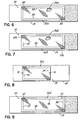
channels 70 in thespacer 51 can be placed at different locations along the perimeter of thecover slip 22. For example, referring toFig. 3 , discontinuities in aspacer 51a on thecover slip 50form channels 71 adjacent the ends ofspacer segments Fig. 4 illustrates a further embodiment in which discontinuities in thespacer 52b form channels 73 intermediate of thespacer segments - A further embodiment of the invention is illustrated in
Figs. 5A-5C . Aspacer 82 extends substantially along almost all of the perimeter of thecover slip 50. Thespacer 82 has twodiscontinuities forming channels 84 at diagonally opposite corners of thecover slip 50. Achamber 86 is bounded by thespacer 82, thecover slip 50 and thesubstrate 24. The hybridization solution is introduced via one of thechannels 84 in a similar process to that described above with respect toFig. 2 . Thespacer 82 shown in the embodiment illustrated inFig. 5 provides two channels or ports in which the hybridization solution can be introduced into thechamber 86 and therefore, is known as a two-channel spacer. -
Fig 5 also illustrates a further embodiment relating toadditional spacers 83 disposed between thecover slip 50 and thesubstrate 24. Theadditional spacers 83 are useful in those applications where additional structure is needed to maintain a fixed distance between thecover slip 50 andsubstrate 24. For example, in some applications, thecover slip 50 may be substantially longer than it is wide and require additional support at its midsection or at some other area or point on thecover slip 50. Theadditional spacers 83 may be identical or similar in shape to thespacer 82, or thespacers 83 may have any cross-sectional shape, for example, round, square, rectangular, etc. The geometry, number and location of theadditional spacers 83 are chosen so that they do not interfere with the hybridization reaction. Theadditional spacers 83 may be printed on thecover slip 50, thesubstrate 24 or both using a process similar to that used to print thespacer 82 or any other suitable process. -
Fig. 6 illustrates another embodiment in which a two-channel spacer 82a is used with thecover slip 50. In this embodiment, aspacer 82a extends along the perimeter of thecover slip 50 and discontinuities in thespacer 82a form diagonally opposedchannels 85. Thechannels 85 cross the perimeter of thecover slip 50 at ends oflongitudinal spacer segments 88. In another embodiment illustrated inFig. 7 , aspacer 82b extends along a perimeter of thecover slip 50 and has discontinuities that form diagonally spaced channels 87. However, In this embodiment, one of the channels 87a crosses the perimeter adjacent an end of thelongitudinal spacer segment 89; and the other channel 87b crosses the perimeter adjacent an end of aspacer segment 90 of thespacer 82b. In a further embodiment illustrated inFig. 8 , a spacer 82c extending along the perimeter of thecover slip 50 has discontinuities formingopposed channels 91 that cross the perimeter intermediate ends ofspacer segments 92, 94. A still further embodiment is illustrated inFig. 9 in which a spacer 82d extends along the perimeter of thecover slip 50 and hasdiscontinuities forming channels 93 adjacent each end of aspacer segment 96. As will be appreciated, in other embodiments, thechannels 91 can be formed at ends of any one of theother spacer segments 86. - In a further embodiment of the cover slip of the present invention illustrated in
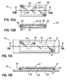
Figs. 10a-10b ; aspacer 102 extends fully along the perimeter of thecover slip 100. In this embodiment, there are no discontinuities in thespacer 102; and therefore, there are no channels that cross the perimeter of alower surface 101 of thecover slip surface 100. In this embodiment, achamber 104 is bounded by theinner sides 105 of thespacer 102 and the confronting inner directedsurfaces respective cover slip 100 andsubstrate 106. This embodiment also illustrates that thecover slip 100 may be sized identically with thesubstrate 106. In use, thecover slip 100 is inverted so that thespacer 102 andchamber 104 are directed upward. A pipette is used to fill thechamber 104 with the hybridization solution; and thereafter, thesubstrate 106 is placed over theinverted cover slip 100, thereby disposing a sample on thesubstrate 106 into the solution filledchamber 104. The assembly of thecover slip 100 andsubstrate 106 is then inverted so that thesubstrate 106 is below thecover slip 100. - In a still further embodiment illustrated in
Figs. 11A-11B , illustrates acover slip 111 with a four-channel spacer 112 extending along its perimeter. Thecover slip 111 has cavities ordepressions 114 formed on an inner directedcover slip surface 116. The purpose of thecavities 114 is to provide a reservoir for additional hybridization solution within achamber 115 as may be required by a particular process. Normally, centers of thecavities 114 lie on a longitudinal centerline of thecover slip 111. However, as will be appreciated, thecavities 114 may be located on any portion of thesurface 116 and further, the number and size of thecavities 114 may be varied to suit the needs of a particular application. In addition, thecavities 114 are shown as being partially spherical. Such cavity geometry is probably the easiest to manufacture, however, in other embodiments, other cavity geometries can be used. - In previous embodiments, the spacers used in the cover glass/substrate combinations are illustrated as continuous segments that are separated by discontinuities forming channels for introducing a hybridization solution. As will be appreciated, referring to
Fig. 12 , aspacer 120 disposed between acover slip 122 andsubstrate 24 may be formed by a series ofspacer segments 124 that have small discontinuities orspaces 126 therebetween. Thespaces 126 are generally sized to inhibit a flow of hybridization solution therethrough and minimize evaporation. Other discontinuities are formed in thespacer 120 to provide one or more larger spaces or channels 128 for introducing a liquid into achamber 129 as previously described. As the liquid is introduced through the channel 128, air can be bled from thechamber 129 via thesmaller spaces 126. One or more of thespaces 126 can be formed into V-shaped spaces 131 (shown in phantom) that can trap air bubbles, so that such bubbles do not interfere with a reaction or process being conducted in thechamber 129. As will be appreciated, thespaces 131 can have other geometric shapes. The relative size of thespaces 126, 128 is determined experimentally depending on the liquid being used, the hydrophobic characteristic of thespacer 120, etc. -
Fig. 13 illustrates a further embodiment of acover slip 130 in which aspacer 132 extends substantially along a majority of the perimeter of thecover slip 130. In this embodiment, oneedge 134 of thecover slip 130 is left open to facilitate the introduction of hybridization solution into achamber 136. - The cover slip described herein substantially improves the quality of a hybridization reaction or other molecular search with which it is used. For example, in a hybridization reaction, the cover slip provides a uniform dispersion of components of a hybridization solution throughout a chamber between the cover slip and a substrate, thereby improving the consistency and quality of the hybridization reaction. The cover slip further permits the volume of the chamber between the cover slip and the substrate to be minimized without adversely affecting the uniformity of the dispersion of the hybridization solution. Thus, the cover slip helps to reduce the quantity of hybridization solution used, and the cost of the hybridization reaction is reduced. Further, the cover slip improves reaction quality, and such improved quality is repeatable from one cover slip to another.
- While the present invention has been illustrated by a description of various embodiments and while these embodiments have been described in considerable detail, it is not the intention of the applicants to restrict or in any way limit the scope of the appended claims to such detail. Additional advantages and modifications will readily appear to those skilled in the art. For example, the spacers between the cover slip and the substrate are described as being formed by printing ink spacers on the cover slip. As will be appreciated, the spacers can alternatively be applied to the substrate instead of the cover slip. In another embodiment, the spacer between the cover slip and the substrate can be formed by spacers applied to, or printed on, both the cover slip and the substrate.
- The various described embodiments illustrate that the cover slip is often smaller than the substrate; however, the size of the cover slip will depend on the application and the user's equipment and practices. Cover slips are known to have a width of about 18-24 mm and a length of about 18-60 mm. Further, in many applications, it is desirable to make the cover slip from a glass having optical properties suitable for use with a microscope. However, with other applications, for example, a hybridization reaction, the cover slip only need be translucent enough to view any hybridization solution beneath the cover slip and air bubbles, if any.
- In the described embodiment, the cover slip is described as being glass. However, as will be appreciated, in an alternative embodiment, other materials, for example, a plastic material, can be used, providing such materials have characteristics and properties that are suitable for a hybridization reaction or other application.
- In the described embodiments, the cover slip and spacer are described as being used in hybridization reactions. However as will be appreciated, the claimed cover slip and spacer provides a tool that can be used more broadly in similar molecular searches that use one of several forms of complementarity to identify the macromolecules of interest among a large number of other molecules. Complementarity is the sequence-specific or shaped-specific molecular recognition that occurs when two molecules bind together. Complementary between a probe molecule and a target molecule can result in the formation of a probe-target complex. This complex can then be located if the probe molecules are tagged with a detectible entity such as a chromophore, fluorophore, radioactivity, or an enzyme.
Claims (27)
- An apparatus of the type used to contain a liquid over a specimen on a substrate for the purpose of performing a hybridization or other molecular complementation reaction, comprising a spacer (51, 51a, 51b, 82, 82a, 82b, 82c, 82d, 83, 102, 112, 120, 132) having a first pair of spacer segments (26, 28, 52, 52a, 52b, 54, 54a, 54b, 88, 89, 96, 124) adapted to contact the substrate (24, 124) and a cover slip (22, 50, 100, 111, 122, 130) having a lower surface and two substantially parallel, opposed longitudinal edges bounding the lower surface, each of the first pair of spacer segments extending along a substantial length of a different one of the opposed longitudinal edges and forming a chamber (34, 72, 129, 136) between the spacer segments, the lower surface of the cover slip and the substrate, the chamber adapted to contain the specimen when the cover slip is placed on the substrate with the spacer sandwiched therebetween, characterized in that the cover slip (22, 50, 100, 111, 122, 130) has a thickness of at least 1.0 mm to provide a cover slip beam stiffness sufficient to react adhesion forces resulting from liquid being introduced between the cover slip (22, 50, 100, 111, 122, 130) and the substrate (24, 123) to maintain a substantially constant distance between the lower surface and the substrate when the liquid is introduced between the cover slip (22, 50, 100, 111, 122, 130) and the substrate (24, 124).
- The apparatus of claim 1 wherein each of the first pair of spacer segments extend along substantially a full length of the opposed longitudinal edges without substantially displacing the liquid from over the specimen.
- The apparatus of either claim 1 or claim 2 wherein the cover slip (50, 100, 111, 122) further comprises two substantially parallel, opposed end edges bounding the surface and the spacer (51, 51 a, 51 b, 82, 82a, 82b, 82c, 82d, 102, 112, 20) further comprises a second pair of spacer segments (62, 62a, 62b, 64, 64a, 64b, 90, 92, 94) extending along a substantial length of the end edges and forming with the first pair of spacer segments at least two channels (70, 71, 73, 84, 85, 87, 87a, 87b, 91, 93, 128) through the spacer.
- The apparatus of claim 3 wherein each of the two channels (85) is located in a different one of the first pair of spacer segments.
- The apparatus of claim 3 wherein one of the two channels (87a) is located in one of the first pair of spacer segments and another of the two channels (87b) is located in one of the second pair of spacer segments.
- The apparatus of claim 3 wherein each of the two channels (91) is located in a different one of the second pair of spacer segments.
- The apparatus of claim 3 wherein each of the two channels (93) is located in one of the first pair of spacer segments.
- The apparatus of claim 3 wherein each of the two channels (93) is located in one of the second pair of spacer segments.
- The apparatus of claim 3 wherein the two channels (84) are located at two points of intersection of the first pair of spacer segments with the second pair of spacer segments.
- The apparatus of either claim 1 or claim 2 wherein the cover slip further comprises two substantially parallel, opposed end edges bounding the surface and the spacer (51, 51a, 51 b) further comprises a second pair of spacer segments, each of the second pair of spacer segments extending along a substantial length of a different one of the end edges and forming with the first pair of spacer segments four channels (70, 71, 73) through the spacer.
- The apparatus of claim 10 wherein each of the four channels (73) is located in a different spacer segment in the first and second pairs of spacer segments.
- The apparatus of claim 10 wherein two channels (70) are located in one of the second pair of spacer segments and two channels (70) are located in another of the second pair of spacer segments.
- The apparatus of claim 10 wherein each of the four channels (71) is located at a different one of four points of intersection of the first pair of spacer segments with the second pair of spacer segments.
- The apparatus of either claim 1 or claim 2 further comprising a second spacer (62, 62a, 64, 64a) disposed inside a perimeter of the spacer (51, 51 a) and in a contacting relationship with the cover slip (50) and the substrate.
- The apparatus of either claim 1 or claim 2 wherein the spacer (120) has discontinuities forming a plurality of spaces (126, 128) through the spacer, one of the spaces (128) forming a channel having a size permitting an introduction of a fluid therethrough and other of the spaces (126) having a size inhibiting a flow of the liquid therethrough.
- The apparatus of either claim 1 or claim 2 wherein the spacer (132) extends adjacent to and along substantially a full length of three of the four edges, the spacer (132) forming an opening across the perimeter along a fourth of the four edges (134).
- The apparatus of any preceding claim wherein the spacer (51, 51 a, 51b, 82, 82a, 82b, 82c, 82d, 83, 102, 112, 120, 132) is affixes to the cover slip (22, 50, 100, 111, 122, 130).
- The apparatus of any one of claims I to 16 wherein the spacer (51, 51 a, 51 b, 82, 82a, 82b, 82c, 82d, 83, 102, 112, 120, 132) is printed on the cover slip (22, 50, 100, 111, 122, 130).
- The apparatus of any preceding claim wherein the chamber (34, 72, 129, 136) has a height in the range from about 30 to 60 micrometers.
- The apparatus of any preceding claim wherein the cover slip (22, 50, 100, 111, 122, 130) is glass.
- A method of preparing a reaction chamber of the type used to contain a liquid over a specimen on a substrate for the purpose of performing a hybridization or other molecular complementation reaction comprising providing a substrate having a specimen on a surface thereof, providing a cover slip (50, 100, 111, 122) having a perimeter with a spacer (51, 51 a, 51b, 82, 82a, 82b, 82c, 82d, 83, 102, 112, 120), placing the cover slip (50, 100, 111, 122) with the spacer (51, 51a, 51b, 82, 82a, 82b, 82c, 82d, 83, 102, 112, 120) on the surface of the substrate with the spacer sandwiched therebetween to form a chamber between the cover slip and the substrate and around the specimen, the spacer (51, 51a, 51 b, 82, 82a, 82b, 82c, 82d, 83, 102, 112, 120) extending over a substantial length of the perimeter, characterized in that the step of providing a cover slip (50, 100, 111, 122) with a spacer (51, 51a, 51b, 82, 82a, 82b, 82c, 82d, 102, 112, 120) comprises affixing a spacer (51, 51a 51b, 82 82a, 82b, 82c, 82d, 83, 102, 112, 120) to a cover slip (50, 100, 111, 122) which has a thickness of at least 1.0 mm; in that the method further comprises introducing the liquid into the chamber via capillary action, and maintaining a substantially constant distance between the cover slip (50, 100, 111, 122) and the substrate throughout the chamber by reacting adhesion forces of the liquid in the chamber with the cover slip (50, 100, 111, 122) by the use of the cover slip (50, 100, 111, 122) with a thickness of at least 1.0 mm.
- The method of claim 21 wherein the spacer (51, 51a, 51b, 82, 82a, 82b, 82c, 82d, 102, 112, 120) has discontinuities forming two spaced apart channels (70, 71, 73, 84, 85, 87, 87a, 87b, 91, 93, 128) that extend through the spacer (51, 51a, 51b, 82, 82a, 82b, 82c, 82d, 102, 112, 120) and communicate with the chamber.
- The method of claim 22 wherein the perimeter of the cover slip (50, 100, 111, 122) has two opposed corners and the method further comprises affixing a spacer (82) to the cover slip (50, 100, 111, 122) having discontinuities forming two channels (84) that extend through the spacer (51, 51 a, 51 b, 82, 82a, 82b, 82c, 82d, 102, 112, 120) and communicate with the chamber, each of the two channels being located at a different one of the two corners.
- The method of claim 22 wherein the perimeter of the cover slip (50, 100, 111, 122) has two opposed sides, each side having opposing ends and the method further comprises affixing a spacer (82c) to the cover slip (50, 100, 111, 122) having discontinuities forming two channels (91) that extend through the spacer (51, 51a, 51 b, 82, 82a, 82b, 82c, 82d, 102, 112, 120) and communicate with the chamber, each of the two channels being located intermediate the opposing ends of a different one of the two opposing sides.
- The method of claim 21 further comprising affixing a spacer (51, 51 a, 51b) to the cover slip (50, 100, 111, 122) having discontinuities forming four spaced apart channels (70, 71, 73) that extend through the spacer (51, 51a, 51b, 82, 82a, 82b, 82c, 82d, 102, 112, 120) and communicate with the chamber.
- The method of claim 21 wherein the perimeter of the cover slip (50, 100, 111, 122) has four sides intersecting at four corners and the method further comprises affixing a spacer (51a) to the cover slip (50, 100, 111, 122) having discontinuities forming four channels that extend through the spacer (51, 51 a, 51 b, 82, 82a, 82b, 82c, 82d, 102, 112, 120) and communicate with the chamber, each of the four channels being located at a different one of the four corners.
- The method of claim 21 wherein the spacer (102) extends continuously around the whole perimeter of the cover slip (50, 100, 111, 122) without any discontinuities.
Applications Claiming Priority (3)
| Application Number | Priority Date | Filing Date | Title |
|---|---|---|---|
| US21602 | 2001-12-12 | ||
| US10/021,602 US7943093B2 (en) | 2001-12-12 | 2001-12-12 | Cover slip |
| PCT/US2002/039384 WO2003050589A2 (en) | 2001-12-12 | 2002-12-10 | Cover slip |
Publications (2)
| Publication Number | Publication Date |
|---|---|
| EP1454176A2 EP1454176A2 (en) | 2004-09-08 |
| EP1454176B1 true EP1454176B1 (en) | 2010-01-20 |
Family
ID=21805134
Family Applications (1)
| Application Number | Title | Priority Date | Filing Date |
|---|---|---|---|
| EP02794211A Expired - Lifetime EP1454176B1 (en) | 2001-12-12 | 2002-12-10 | Cover slip |
Country Status (5)
| Country | Link |
|---|---|
| US (1) | US7943093B2 (en) |
| EP (1) | EP1454176B1 (en) |
| AU (1) | AU2002359658A1 (en) |
| DE (1) | DE60235192D1 (en) |
| WO (1) | WO2003050589A2 (en) |
Families Citing this family (50)
| Publication number | Priority date | Publication date | Assignee | Title |
|---|---|---|---|---|
| DE10340473B4 (en) * | 2003-09-03 | 2007-08-23 | Eppendorf Ag | Cover of a hybridization chamber |
| EP1733226B1 (en) | 2004-04-07 | 2015-07-29 | Levine, Robert Aaron | Disposable chamber for analyzing biologic fluids |
| US7547424B2 (en) * | 2004-09-21 | 2009-06-16 | Van Andel Research Institute | Method and apparatus for making partitioned slides |
| US20100139420A1 (en) * | 2006-09-27 | 2010-06-10 | Gabriel John Simon Ohlsson | Cell for confinement of very small volumes of soft matter and fluids |
| US20090017528A1 (en) * | 2007-07-12 | 2009-01-15 | Pei-Tai Chen | Nucleic Acid Hybridization Device |
| US20100215936A1 (en) * | 2009-02-20 | 2010-08-26 | Canale Joseph E | Coating for inhibiting glass to glass adherence |
| EP2491395B1 (en) | 2009-10-21 | 2015-09-16 | The Scripps Research Institute | Method of using non-rare cells to detect rare cells |
| BR112014013956A8 (en) * | 2011-12-09 | 2017-06-13 | Marienfeld Gerd | device, system and method for identifying circulating tumor cells |
| WO2014205576A1 (en) * | 2013-06-26 | 2014-12-31 | Alentic Microscience Inc. | Sample processing improvements for microscopy |
| US10876937B2 (en) | 2013-10-04 | 2020-12-29 | Biogenex Laboratories, Inc. | Assembly for forming microchamber for inverted substrate |
| US20150198580A1 (en) * | 2014-01-13 | 2015-07-16 | General Electric Company | Coverslip and methods for removing |
| WO2015112955A1 (en) | 2014-01-27 | 2015-07-30 | Epic Sciences, Inc. | Circulating tumor cell diagnostics for prostate cancer biomarkers |
| EA201691682A1 (en) | 2014-02-21 | 2017-02-28 | Эпик Сайенсиз, Инк. | METHODS FOR ANALYZING RARE CIRCULATING CELLS IN THE BLOOD |
| RU2018107453A (en) * | 2015-08-10 | 2019-09-12 | Эссенликс Корп. | DEVICES FOR ANALYSIS AND METHODS IN BIOLOGY / CHEMISTRY, PROVIDING SIMPLIFIED STAGES, SAMPLES OF SMALL VOLUME, INCREASED SPEED AND EASE OF APPLICATION |
| KR101982330B1 (en) | 2015-09-14 | 2019-05-24 | 에센릭스 코프. | Apparatus and systems for collecting and analyzing vapor condensate, in particular condensate, and methods of using the apparatus and system |
| MY194887A (en) | 2015-09-14 | 2022-12-21 | Essenlix Corp | Device and System for Analyzing a Sample, Particularly Blood, as Well as Methods of Using The Same |
| US10317662B2 (en) | 2016-04-08 | 2019-06-11 | Alentic Microscience Inc. | Sample processing for microscopy |
| CA3048002A1 (en) | 2016-12-21 | 2018-06-28 | Essenlix Corporation | Devices and methods for authenticating a sample and use of the same |
| JP7003158B2 (en) | 2017-02-07 | 2022-01-20 | エッセンリックス コーポレーション | Compressed open flow assay and use |
| CN120685901A (en) | 2017-02-08 | 2025-09-23 | 上海宜晟生物科技有限公司 | Digital measurement |
| WO2018148764A1 (en) | 2017-02-08 | 2018-08-16 | Essenlix Corporation | Molecular manipulation and assay with controlled temperature |
| US11927560B2 (en) | 2017-02-08 | 2024-03-12 | Essenlix Corporation | Bio/chemical material extraction and assay |
| CA3053005A1 (en) | 2017-02-08 | 2018-08-16 | Essenlix Corporation | Sample collection and handling for delayed analysis |
| CA3052809A1 (en) | 2017-02-08 | 2018-08-23 | Essenlix Corporation | Qmax assays and applications |
| WO2018148607A1 (en) | 2017-02-09 | 2018-08-16 | Essenlix Corporation | Assay using different spacing heights |
| CN110770572B (en) | 2017-02-09 | 2023-08-18 | Essenlix公司 | Colorimetric assay |
| CN110998325B (en) | 2017-02-09 | 2024-08-16 | 上海宜晟生物科技有限公司 | Amplification assay |
| CA3053295A1 (en) | 2017-02-15 | 2018-08-23 | Essenlix Corporation | Assay with rapid temperature change |
| JP7107953B2 (en) | 2017-02-16 | 2022-07-27 | エッセンリックス コーポレーション | Assays using textured surfaces |
| WO2018231877A1 (en) | 2017-06-12 | 2018-12-20 | Essenlix Corporation | Homogeneous assay |
| US11280706B2 (en) | 2017-08-01 | 2022-03-22 | Essenlix Corporation | Dilution calibration |
| WO2019028133A1 (en) | 2017-08-01 | 2019-02-07 | Essenlix Corporation | Devices and methods for examining drug effects on microorganisms |
| US11243201B2 (en) | 2017-08-01 | 2022-02-08 | Essenlix Corporation | Sample collection, holding and assaying |
| US12403465B2 (en) | 2017-10-11 | 2025-09-02 | Essenlix Corporation | Containing a liquid sample |
| US11393561B2 (en) | 2017-10-13 | 2022-07-19 | Essenlix Corporation | Devices and methods for authenticating a medical test and use of the same |
| US10807095B2 (en) | 2017-10-26 | 2020-10-20 | Essenlix Corporation | Making and tracking assay card |
| US11237113B2 (en) | 2017-10-26 | 2022-02-01 | Essenlix Corporation | Rapid pH measurement |
| WO2019084515A1 (en) * | 2017-10-26 | 2019-05-02 | Essenlix Corporation | Devices and methods for tissue and cell staining |
| US11609224B2 (en) | 2017-10-26 | 2023-03-21 | Essenlix Corporation | Devices and methods for white blood cell analyses |
| US11648551B2 (en) | 2017-12-12 | 2023-05-16 | Essenlix Corporation | Sample manipulation and assay with rapid temperature change |
| US11510608B2 (en) | 2017-12-14 | 2022-11-29 | Essenlix Corporation | Devices, systems, and methods for monitoring hair |
| US11156606B2 (en) | 2018-01-11 | 2021-10-26 | Essenlix Corporation | Homogeneous assay (II) |
| US11885952B2 (en) | 2018-07-30 | 2024-01-30 | Essenlix Corporation | Optics, device, and system for assaying and imaging |
| WO2021011944A2 (en) * | 2019-07-18 | 2021-01-21 | Essenlix Corporation | Imaging based homogeneous assay |
| CN110658620A (en) * | 2019-11-05 | 2020-01-07 | 安图实验仪器(郑州)有限公司 | Cover glass |
| JP7088250B2 (en) * | 2020-09-23 | 2022-06-21 | 大日本印刷株式会社 | Microscope image calibration slide glass |
| WO2022136848A1 (en) * | 2020-12-22 | 2022-06-30 | Oxford Immune Algorithmics Ltd | Wafer for carrying biological sample |
| EP4030216A1 (en) * | 2021-01-14 | 2022-07-20 | ibidi GmbH | Sample chamber for the microscopy of cells and system comprising a sample holder and a sample chamber |
| CN115219308B (en) * | 2022-08-31 | 2025-12-09 | 复旦大学附属中山医院青浦分院(上海市青浦区中心医院) | Film-making method and imaging method for high-resolution imaging of complete thick biological tissues |
| WO2024234301A1 (en) * | 2023-05-16 | 2024-11-21 | Mgi Tech Co., Ltd. | Improved flow cells, systems, and methods |
Family Cites Families (33)
| Publication number | Priority date | Publication date | Assignee | Title |
|---|---|---|---|---|
| US1654369A (en) | 1925-09-03 | 1927-12-27 | Harry W George | Microscope attachment |
| US2942520A (en) | 1955-12-20 | 1960-06-28 | George G Rose | Tissue culture device |
| US3556633A (en) | 1969-01-17 | 1971-01-19 | Winifred Liu Mutschmann | Specimen carrying slide with runoff trough |
| US3572892A (en) | 1969-02-10 | 1971-03-30 | Richardson Merrell Inc | Multiple well tissue culture slide |
| US3879106A (en) * | 1973-04-11 | 1975-04-22 | Pelam Inc | Microscope slide cover slip |
| US4022521A (en) | 1974-02-19 | 1977-05-10 | Honeywell Inc. | Microscope slide |
| US3960268A (en) | 1975-09-15 | 1976-06-01 | Villa Precision, Inc. | Frame for supporting frangible sheet materials |
| US4171866A (en) * | 1978-04-20 | 1979-10-23 | Tolles Walter E | Disposable volumetric slide |
| US4260392A (en) | 1978-07-07 | 1981-04-07 | Technicon Instruments Corporation | Method and apparatus for obtaining an aliquot of a liquid in a gel medium |
| US4501496A (en) | 1982-05-07 | 1985-02-26 | Griffin Gladys B | Specimen slide for analysis of liquid specimens |
| US4447140A (en) * | 1982-09-29 | 1984-05-08 | Campbell Jeptha E | Microscope slides |
| US4481246A (en) | 1982-11-15 | 1984-11-06 | Sybron Corporation | Microscope slide with raised marking surface |
| US4624882A (en) | 1982-11-15 | 1986-11-25 | Sybron Corporation | Microscope slide with raised marking surface |
| EP0117262B1 (en) | 1983-02-25 | 1988-04-20 | Winfried Dr. med. Stöcker | Processes and devices for examinations on immobilised biological material |
| US4595561A (en) | 1984-11-19 | 1986-06-17 | Martin Marietta Corporation | Liquid sample holder |
| US4731335A (en) | 1985-09-13 | 1988-03-15 | Fisher Scientific Company | Method for treating thin samples on a surface employing capillary flow |
| US4679914A (en) | 1985-09-13 | 1987-07-14 | Erie Scientific Company | Microscope slide with top and bottom marking surfaces |
| US4790640A (en) | 1985-10-11 | 1988-12-13 | Nason Frederic L | Laboratory slide |
| US5002736A (en) | 1987-03-31 | 1991-03-26 | Fisher Scientific Co. | Microscope slide and slide assembly |
| DE3830721A1 (en) | 1988-09-09 | 1990-03-22 | Michael Dr Menton | Slide for use in laboratories, especially in medical laboratories |
| US5192503A (en) * | 1990-05-23 | 1993-03-09 | Mcgrath Charles M | Probe clip in situ assay apparatus |
| US5349436A (en) | 1992-12-02 | 1994-09-20 | Harry Fisch | Biological assembly |
| US5364790A (en) | 1993-02-16 | 1994-11-15 | The Perkin-Elmer Corporation | In situ PCR amplification system |
| US5571721A (en) | 1994-05-05 | 1996-11-05 | Erie Scientific Company | Improved biological culture slide and method of making same |
| GB9506312D0 (en) * | 1995-03-28 | 1995-05-17 | Medical Res Council | Improvements in or relating to sample processing |
| AUPN923596A0 (en) | 1996-04-12 | 1996-05-09 | Australian Biomedical Corporation Limited | Method and apparatus for treatment of human or animal cell samples |
| US5939251A (en) | 1996-07-12 | 1999-08-17 | Hu; Min | Apparatus and method for simplifying the processes in creating a sealed space on slides to conduct molecular biological reactions therein |
| US6489171B1 (en) * | 1997-04-18 | 2002-12-03 | Cell Marque Corporation | Chemical dispensing system and method |
| US5812312A (en) | 1997-09-04 | 1998-09-22 | Lorincz; Andrew Endre | Microscope slide |
| DE19753598C1 (en) | 1997-12-03 | 1999-07-01 | Micronas Intermetall Gmbh | Device for measuring physiological parameters |
| US6037168A (en) | 1997-12-31 | 2000-03-14 | Cytonix Corporation | Microbiological assembly comprising resealable closure means |
| US6358475B1 (en) | 1998-05-27 | 2002-03-19 | Becton, Dickinson And Company | Device for preparing thin liquid for microscopic analysis |
| US6180314B1 (en) | 1998-05-27 | 2001-01-30 | Becton, Dickinson And Company | Method for preparing thin liquid samples for microscopic analysis |
-
2001
- 2001-12-12 US US10/021,602 patent/US7943093B2/en not_active Expired - Lifetime
-
2002
- 2002-12-10 DE DE60235192T patent/DE60235192D1/en not_active Expired - Lifetime
- 2002-12-10 AU AU2002359658A patent/AU2002359658A1/en not_active Abandoned
- 2002-12-10 WO PCT/US2002/039384 patent/WO2003050589A2/en not_active Ceased
- 2002-12-10 EP EP02794211A patent/EP1454176B1/en not_active Expired - Lifetime
Also Published As
| Publication number | Publication date |
|---|---|
| WO2003050589A3 (en) | 2004-03-11 |
| US20030109059A1 (en) | 2003-06-12 |
| DE60235192D1 (en) | 2010-03-11 |
| EP1454176A2 (en) | 2004-09-08 |
| AU2002359658A1 (en) | 2003-06-23 |
| WO2003050589A2 (en) | 2003-06-19 |
| US7943093B2 (en) | 2011-05-17 |
| AU2002359658A8 (en) | 2003-06-23 |
Similar Documents
| Publication | Publication Date | Title |
|---|---|---|
| US7943093B2 (en) | Cover slip | |
| US7468160B2 (en) | Devices and methods for performing array based assays | |
| US10227644B2 (en) | Apparatus and methods for parallel processing of microvolume liquid reactions | |
| US8563275B2 (en) | Method and device for detecting the presence of a single target nucleic acid in a sample | |
| EP1246698B1 (en) | Ultra high throughput sampling and analysis systems and methods | |
| US7833719B2 (en) | Apparatus and methods for parallel processing of micro-volume liquid reactions | |
| AU733523B2 (en) | Laminated assembly for active bioelectronic devices | |
| CN104302400B (en) | System and method for accommodating biological sample | |
| US20030231987A1 (en) | Devices and methods for performing array based assays | |
| EP1373566B1 (en) | Polynucleotide analysis using combinatorial pcr | |
| US20030231983A1 (en) | Fluid containment structure | |
| WO2005028629A2 (en) | Whole genome expression analysis system | |
| EP1374989A2 (en) | Array assay devices and methods of using the same | |
| JP7550055B2 (en) | Analytical system including a microfluidic device, a microfluidic device and related methods | |
| US20040235036A1 (en) | Devices and methods for detecting genetic sequences | |
| EP1866090B1 (en) | High throughput polymer-based microarray slide | |
| EP1374990A2 (en) | Array assay devices and methods of using the same | |
| KR20060093063A (en) | Macroporous Supports for Chemical Amplification Reactions | |
| KR20150089025A (en) | Case for containing biological samples and corresponding method of use | |
| US20030232344A1 (en) | Hybridization process for arrays | |
| KR102036922B1 (en) | Analysis module and manufacturing method thereof | |
| US20060154281A1 (en) | Reaction chamber | |
| US7341865B1 (en) | Liquid delivery devices and methods | |
| US20090156428A1 (en) | Multi-mode microarray apparatus and method for concurrent and sequential biological assays | |
| US6218116B1 (en) | Method and device for treatment by complexing of a liquid medium |
Legal Events
| Date | Code | Title | Description |
|---|---|---|---|
| PUAI | Public reference made under article 153(3) epc to a published international application that has entered the european phase |
Free format text: ORIGINAL CODE: 0009012 |
|
| 17P | Request for examination filed |
Effective date: 20040602 |
|
| AK | Designated contracting states |
Kind code of ref document: A2 Designated state(s): AT BE BG CH CY CZ DE DK EE ES FI FR GB GR IE IT LI LU MC NL PT SE SI SK TR |
|
| AX | Request for extension of the european patent |
Extension state: AL LT LV MK RO |
|
| RIN1 | Information on inventor provided before grant (corrected) |
Inventor name: SANFORD, PAUL Inventor name: ROBINSON, MARK, G. Inventor name: MOORE, DAVID, J. Inventor name: COSBY, N., GUY Inventor name: ADRIEN, CHRISTOPHER, L. |
|
| RIN1 | Information on inventor provided before grant (corrected) |
Inventor name: SANFORD, PAUL Inventor name: ROBINSON, MARK, G. Inventor name: MOORE, DAVID, J. Inventor name: COSBY, N., GUY Inventor name: ADRIEN, CHRISTOPHER, L. |
|
| GRAP | Despatch of communication of intention to grant a patent |
Free format text: ORIGINAL CODE: EPIDOSNIGR1 |
|
| GRAS | Grant fee paid |
Free format text: ORIGINAL CODE: EPIDOSNIGR3 |
|
| GRAA | (expected) grant |
Free format text: ORIGINAL CODE: 0009210 |
|
| AK | Designated contracting states |
Kind code of ref document: B1 Designated state(s): DE DK FR GB |
|
| REG | Reference to a national code |
Ref country code: GB Ref legal event code: FG4D |
|
| REF | Corresponds to: |
Ref document number: 60235192 Country of ref document: DE Date of ref document: 20100311 Kind code of ref document: P |
|
| PLBE | No opposition filed within time limit |
Free format text: ORIGINAL CODE: 0009261 |
|
| STAA | Information on the status of an ep patent application or granted ep patent |
Free format text: STATUS: NO OPPOSITION FILED WITHIN TIME LIMIT |
|
| 26N | No opposition filed |
Effective date: 20101021 |
|
| PG25 | Lapsed in a contracting state [announced via postgrant information from national office to epo] |
Ref country code: DK Free format text: LAPSE BECAUSE OF FAILURE TO SUBMIT A TRANSLATION OF THE DESCRIPTION OR TO PAY THE FEE WITHIN THE PRESCRIBED TIME-LIMIT Effective date: 20100120 |
|
| REG | Reference to a national code |
Ref country code: FR Ref legal event code: ST Effective date: 20110831 |
|
| PG25 | Lapsed in a contracting state [announced via postgrant information from national office to epo] |
Ref country code: FR Free format text: LAPSE BECAUSE OF NON-PAYMENT OF DUE FEES Effective date: 20110103 |
|
| REG | Reference to a national code |
Ref country code: DE Ref legal event code: R082 Ref document number: 60235192 Country of ref document: DE Representative=s name: 2K PATENTANWAELTE BLASBERG KEWITZ & REICHEL PA, DE Ref country code: DE Ref legal event code: R081 Ref document number: 60235192 Country of ref document: DE Owner name: ERIE SCIENTIFIC LLC (N.D.GES.D. STAATES DELAWA, US Free format text: FORMER OWNER: ERIE SCIENTIFIC COMPANY, PORTSMOUTH, N.H., US Ref country code: DE Ref legal event code: R081 Ref document number: 60235192 Country of ref document: DE Owner name: NEW ERIE SCIENTIFIC LLC, PORTSMOUTH, US Free format text: FORMER OWNER: ERIE SCIENTIFIC COMPANY, PORTSMOUTH, N.H., US |
|
| REG | Reference to a national code |
Ref country code: DE Ref legal event code: R082 Ref document number: 60235192 Country of ref document: DE Representative=s name: 2K PATENTANWAELTE BLASBERG KEWITZ & REICHEL PA, DE Ref country code: DE Ref legal event code: R081 Ref document number: 60235192 Country of ref document: DE Owner name: NEW ERIE SCIENTIFIC LLC, PORTSMOUTH, US Free format text: FORMER OWNER: ERIE SCIENTIFIC LLC (N.D.GES.D. STAATES DELAWARE), DOVER, DE, US |
|
| REG | Reference to a national code |
Ref country code: GB Ref legal event code: 732E Free format text: REGISTERED BETWEEN 20190808 AND 20190814 |
|
| REG | Reference to a national code |
Ref country code: GB Ref legal event code: 732E Free format text: REGISTERED BETWEEN 20191219 AND 20191224 |
|
| PGFP | Annual fee paid to national office [announced via postgrant information from national office to epo] |
Ref country code: DE Payment date: 20211227 Year of fee payment: 20 Ref country code: GB Payment date: 20211227 Year of fee payment: 20 |
|
| REG | Reference to a national code |
Ref country code: DE Ref legal event code: R071 Ref document number: 60235192 Country of ref document: DE |
|
| REG | Reference to a national code |
Ref country code: GB Ref legal event code: PE20 Expiry date: 20221209 |
|
| PG25 | Lapsed in a contracting state [announced via postgrant information from national office to epo] |
Ref country code: GB Free format text: LAPSE BECAUSE OF EXPIRATION OF PROTECTION Effective date: 20221209 |