EP1453190A1 - Connection between a rectifier and a voltage regulator in a vehicle alternator - Google Patents
Connection between a rectifier and a voltage regulator in a vehicle alternator Download PDFInfo
- Publication number
- EP1453190A1 EP1453190A1 EP04003304A EP04003304A EP1453190A1 EP 1453190 A1 EP1453190 A1 EP 1453190A1 EP 04003304 A EP04003304 A EP 04003304A EP 04003304 A EP04003304 A EP 04003304A EP 1453190 A1 EP1453190 A1 EP 1453190A1
- Authority
- EP
- European Patent Office
- Prior art keywords
- terminal
- detector
- phase
- alternator
- detector terminal
- Prior art date
- Legal status (The legal status is an assumption and is not a legal conclusion. Google has not performed a legal analysis and makes no representation as to the accuracy of the status listed.)
- Granted
Links
- 238000003466 welding Methods 0.000 claims abstract description 24
- 238000000034 method Methods 0.000 claims abstract description 7
- 238000004804 winding Methods 0.000 claims abstract description 6
- 239000000463 material Substances 0.000 claims description 9
- 238000010030 laminating Methods 0.000 claims description 4
- CWYNVVGOOAEACU-UHFFFAOYSA-N Fe2+ Chemical compound [Fe+2] CWYNVVGOOAEACU-UHFFFAOYSA-N 0.000 claims description 2
- 229910001369 Brass Inorganic materials 0.000 description 3
- 239000010951 brass Substances 0.000 description 3
- XEEYBQQBJWHFJM-UHFFFAOYSA-N Iron Chemical compound [Fe] XEEYBQQBJWHFJM-UHFFFAOYSA-N 0.000 description 2
- 238000005452 bending Methods 0.000 description 2
- 238000000465 moulding Methods 0.000 description 2
- 230000005284 excitation Effects 0.000 description 1
- 229910052742 iron Inorganic materials 0.000 description 1
- 238000004519 manufacturing process Methods 0.000 description 1
Images


Classifications
-
- H—ELECTRICITY
- H01—ELECTRIC ELEMENTS
- H01R—ELECTRICALLY-CONDUCTIVE CONNECTIONS; STRUCTURAL ASSOCIATIONS OF A PLURALITY OF MUTUALLY-INSULATED ELECTRICAL CONNECTING ELEMENTS; COUPLING DEVICES; CURRENT COLLECTORS
- H01R4/00—Electrically-conductive connections between two or more conductive members in direct contact, i.e. touching one another; Means for effecting or maintaining such contact; Electrically-conductive connections having two or more spaced connecting locations for conductors and using contact members penetrating insulation
- H01R4/02—Soldered or welded connections
- H01R4/029—Welded connections
-
- B—PERFORMING OPERATIONS; TRANSPORTING
- B23—MACHINE TOOLS; METAL-WORKING NOT OTHERWISE PROVIDED FOR
- B23K—SOLDERING OR UNSOLDERING; WELDING; CLADDING OR PLATING BY SOLDERING OR WELDING; CUTTING BY APPLYING HEAT LOCALLY, e.g. FLAME CUTTING; WORKING BY LASER BEAM
- B23K11/00—Resistance welding; Severing by resistance heating
- B23K11/002—Resistance welding; Severing by resistance heating specially adapted for particular articles or work
- B23K11/0026—Welding of thin articles
-
- B—PERFORMING OPERATIONS; TRANSPORTING
- B23—MACHINE TOOLS; METAL-WORKING NOT OTHERWISE PROVIDED FOR
- B23K—SOLDERING OR UNSOLDERING; WELDING; CLADDING OR PLATING BY SOLDERING OR WELDING; CUTTING BY APPLYING HEAT LOCALLY, e.g. FLAME CUTTING; WORKING BY LASER BEAM
- B23K11/00—Resistance welding; Severing by resistance heating
- B23K11/34—Preliminary treatment
-
- B—PERFORMING OPERATIONS; TRANSPORTING
- B23—MACHINE TOOLS; METAL-WORKING NOT OTHERWISE PROVIDED FOR
- B23K—SOLDERING OR UNSOLDERING; WELDING; CLADDING OR PLATING BY SOLDERING OR WELDING; CUTTING BY APPLYING HEAT LOCALLY, e.g. FLAME CUTTING; WORKING BY LASER BEAM
- B23K33/00—Specially-profiled edge portions of workpieces for making soldering or welding connections; Filling the seams formed thereby
- B23K33/004—Filling of continuous seams
- B23K33/008—Filling of continuous seams for automotive applications
-
- H—ELECTRICITY
- H02—GENERATION; CONVERSION OR DISTRIBUTION OF ELECTRIC POWER
- H02K—DYNAMO-ELECTRIC MACHINES
- H02K11/00—Structural association of dynamo-electric machines with electric components or with devices for shielding, monitoring or protection
- H02K11/04—Structural association of dynamo-electric machines with electric components or with devices for shielding, monitoring or protection for rectification
- H02K11/049—Rectifiers associated with stationary parts, e.g. stator cores
- H02K11/05—Rectifiers associated with casings, enclosures or brackets
-
- H—ELECTRICITY
- H02—GENERATION; CONVERSION OR DISTRIBUTION OF ELECTRIC POWER
- H02K—DYNAMO-ELECTRIC MACHINES
- H02K19/00—Synchronous motors or generators
- H02K19/16—Synchronous generators
- H02K19/36—Structural association of synchronous generators with auxiliary electric devices influencing the characteristic of the generator or controlling the generator, e.g. with impedances or switches
-
- H—ELECTRICITY
- H02—GENERATION; CONVERSION OR DISTRIBUTION OF ELECTRIC POWER
- H02K—DYNAMO-ELECTRIC MACHINES
- H02K19/00—Synchronous motors or generators
- H02K19/16—Synchronous generators
- H02K19/36—Structural association of synchronous generators with auxiliary electric devices influencing the characteristic of the generator or controlling the generator, e.g. with impedances or switches
- H02K19/365—Structural association of synchronous generators with auxiliary electric devices influencing the characteristic of the generator or controlling the generator, e.g. with impedances or switches with a voltage regulator
-
- B—PERFORMING OPERATIONS; TRANSPORTING
- B23—MACHINE TOOLS; METAL-WORKING NOT OTHERWISE PROVIDED FOR
- B23K—SOLDERING OR UNSOLDERING; WELDING; CLADDING OR PLATING BY SOLDERING OR WELDING; CUTTING BY APPLYING HEAT LOCALLY, e.g. FLAME CUTTING; WORKING BY LASER BEAM
- B23K2101/00—Articles made by soldering, welding or cutting
- B23K2101/36—Electric or electronic devices
- B23K2101/38—Conductors
-
- H—ELECTRICITY
- H02—GENERATION; CONVERSION OR DISTRIBUTION OF ELECTRIC POWER
- H02K—DYNAMO-ELECTRIC MACHINES
- H02K5/00—Casings; Enclosures; Supports
- H02K5/04—Casings or enclosures characterised by the shape, form or construction thereof
- H02K5/22—Auxiliary parts of casings not covered by groups H02K5/06-H02K5/20, e.g. shaped to form connection boxes or terminal boxes
- H02K5/225—Terminal boxes or connection arrangements
Definitions
- the present invention relates to an alternator for use in an automotive vehicle.
- An alternator having a phase terminal sandwiched by a detector terminal led out from a voltage regulator is shown in JP-A-11-164518.
- the phase terminal extending from a terminal base of a rectifier is electrically connected to the detector terminal by resistance welding. If the detector terminal is made of a material having a relatively high electrical resistance, such as a nickel-plated iron plate, the phase terminal sandwiched by the detector terminal can be welded to the detector terminal without difficulty. This is because most of the welding current flows through the phase terminal sandwiched by the detector terminal without bypassing a welding portion.
- the detector terminal is made of a material having a high electrical conductivity such as a tin-plated brass, an amount of current flowing through the bent portion of the detector terminal will increase, and thereby an amount of welding current flowing through the phase terminal will decrease. Therefore, there occurs a problem that the phase terminal cannot be well connected to the detector terminal by resistance welding.
- the present invention has been made in view of the above-mentioned problem, and an object of the present invention is to provide an improved structure of the detector terminal with which the phase terminal is sandwiched.
- the improved structure in the alternator By employing the improved structure in the alternator, the phase terminal can be well connected to the detector terminal, not depending on a material of the detector terminal.
- the automotive alternator includes an armature having multi-phase windings and a rotor for providing a magnetic field for the armature. Alternating current generated in the armature is rectified into direct current by a rectifier, and output voltage of the armature is controlled to a predetermined level by a voltage regulator.
- the rectifier and the regulator are mounted on the alternator.
- a phase terminal for taking out a phase voltage from one of the phase windings extends from the rectifier, while a detector terminal to be connected to the phase terminal extends from the voltage regulator.
- the detector terminal is bent in a U-shape, thereby forming a first portion, a second portion positioned in parallel to the first portion and a U-shaped portion positioned between the first and the second portions.
- the phase terminal is sandwiched between the first and the second portions and welded thereto by resistance welding.
- a slit window is formed in the U-shaped portion. Since the electrical resistance in the U-shaped portion is increased by the slit window, the bypassing current is suppressed and a sufficient amount of welding current flows through the phase terminal. Accordingly, the phase terminal is surely connected to the detector terminal by the resistance welding without depending on a material, i.e., electrical resistance, forming the detector terminal.
- the position of the slit window is not limited to the U-shaped portion, but the slit window may be positioned at other places as long as the slit window suppresses the bypassing current in the resistance welding process.
- the detector terminal may be made by laminating two or more thin plates.
- An alternator 1 for use in an automotive vehicle is composed of: an armature 2, a rotor 3, a front frame 41, a rear frame 42, a rectifier 5, a brush device 6, a voltage regulator 7, and other associated components.
- the armature 2 is fixed between the front frame 41 and rear frame 42, and the rotor 3 is rotatably supported by the two frames 41, 42.
- the rear axial end of the alternator 1 is covered with a rear cover 8.
- Excitation current is supplied to a field coil wound on the rotor 3 from the brush device 6 through slip rings connected to a rotor shaft.
- Alternating current generated in the armature 2 is rectified into direct current by the rectifier 5, and output voltage generated in the alternator 1 is controlled to a predetermined level by the voltage regulator 7.
- the rectifier 5 is composed of a plus terminal heatsink plate 57, a minus terminal heatsink plate 58, and a terminal base 51 interposed between two heatsink plates 57, 58. Both heatsink plates 57, 58 and the terminal base 51 is laminated in the axial direction as better seen in FIG. 1.
- the terminal base 51 includes plural connecting terminals 52 molded together by insert-molding.
- a phase terminal 53 for leading a phase voltage from a three-phase winding of the armature 2 is included in the connecting terminals 52.
- the voltage regulator 7 includes a connector case 71.
- the connector case 71 is fixed to the plus terminal heatsink plate 57 with screws via a mounting arm 73.
- a terminal arm 75 is fixed to the rear frame 42 with a screw together with the minus heatsink plate 58.
- the connector case 71 has connector terminals 72 for communicating with an electronic control unit of the vehicle and a detector terminal 74 led out from the connector case 71.
- Those terminals 72, 74 are molded together with the connector case 71 by insert-molding.
- the detector terminal 74 is electrically connected to the phase terminal 53 by resistance welding. Frequencies of the phase voltage appearing at the phase terminal 53 and the phase voltage itself are led to the voltage regulator 7 through the detector terminal 74.
- the voltage regulator 7 controls an amount of current supplied to the field coil of the rotor 3 based on the signals fed from the detector terminal 74.
- Information including rotational speed of the rotor 3 and a level of the generated voltage in the alternator 1 is sent out to the electronic control unit from the connector terminals 72.
- the detector terminal 74 extending from the connector case 71 is formed by bending laminated two plates into a U-shape.
- the detector terminal 74 is composed of a first portion 74A, a second portion 74B and a U-shaped portion 74C.
- a slit window 74D is formed in the U-shaped portion.
- the phase terminal 53 is sandwiched between the first portion 74A and the second portion 74B.
- a pair of welding electrodes 80, 82 are attached to both sides of the detector terminal 74, and the phase terminal 53 is electrically connected to the detector terminal 74 by resistance welding.
- a cross-sectional area S2 of the U-shaped portion 74C is made much smaller than an area S1 where the phase terminal 53 contacts the detector terminal 74.
- the cross-sectional area S2 is made smaller by making the slit window 74D.
- the welding current flowing through the first portion 74A, the phase terminal 53 and the second portion 74B can be made sufficiently large by suppressing current flowing through the U-shaped portion, i.e., the cross-sectional area S2.
- the phase terminal 53 is well welded to the detector terminal 74.
- the detector terminal 74 is made by laminating two tin-plated brass plates which have a lower electrical resistance than nickel-plated ferrous material. Forming the detector terminal 74 by laminating thin plates, the slit window 74D can be easily made by stamping.
- the thin plate may be made common to other terminal plates used in the voltage regulator 7 or the rectifier 5, and thus, the manufacturing costs can be reduced.
- the resistance welding can be successfully performed even when the detector terminal 74 is made of a material having a low electrical resistance. If the tin-plated brass plate is used as in the present embodiment and if no slit window 74D is formed as in the conventional device, the bypass current flowing through the U-shaped portion will become too large. Therefore, it will be difficult to successfully weld the phase terminal 53 to the detector terminal 74 by resistance welding.
- the slit window 74D in the U-shaped portion 74C the resistance welding can be successfully performed irrespective of the material forming the detector terminal 74.
- the process of bending i.e., the process of forming the U-shaped portion, can be easily carried out.
- the present invention is not limited to the foregoing embodiment, but it may be variously modified.
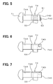
- the slit window 74D may be formed on the second portion 74B of the detector terminal 74, as shown in FIG. 6.
- the slit window 74D may be formed on the first portion 74A of the detector terminal 74, as shown in FIG. 7.
- the positions of the slit window 74D are not limited to the examples shown above, it may be made at other places as long as it suppresses the bypassing current at the resistance welding.
- the number of the slit windows 74D is not limited to one, but more than two slit windows may be formed.
- one slit window may be made on each of the first portion 74A and the second portion 74B.
Landscapes
- Engineering & Computer Science (AREA)
- Power Engineering (AREA)
- Mechanical Engineering (AREA)
- Synchronous Machinery (AREA)
- Motor Or Generator Frames (AREA)
- Manufacture Of Motors, Generators (AREA)
Abstract
Description
- The present invention relates to an alternator for use in an automotive vehicle.
- An alternator having a phase terminal sandwiched by a detector terminal led out from a voltage regulator is shown in JP-A-11-164518. The phase terminal extending from a terminal base of a rectifier is electrically connected to the detector terminal by resistance welding. If the detector terminal is made of a material having a relatively high electrical resistance, such as a nickel-plated iron plate, the phase terminal sandwiched by the detector terminal can be welded to the detector terminal without difficulty. This is because most of the welding current flows through the phase terminal sandwiched by the detector terminal without bypassing a welding portion.
- However, if the detector terminal is made of a material having a high electrical conductivity such as a tin-plated brass, an amount of current flowing through the bent portion of the detector terminal will increase, and thereby an amount of welding current flowing through the phase terminal will decrease. Therefore, there occurs a problem that the phase terminal cannot be well connected to the detector terminal by resistance welding.
- The present invention has been made in view of the above-mentioned problem, and an object of the present invention is to provide an improved structure of the detector terminal with which the phase terminal is sandwiched. By employing the improved structure in the alternator, the phase terminal can be well connected to the detector terminal, not depending on a material of the detector terminal.
- The automotive alternator includes an armature having multi-phase windings and a rotor for providing a magnetic field for the armature. Alternating current generated in the armature is rectified into direct current by a rectifier, and output voltage of the armature is controlled to a predetermined level by a voltage regulator. The rectifier and the regulator are mounted on the alternator.
- A phase terminal for taking out a phase voltage from one of the phase windings extends from the rectifier, while a detector terminal to be connected to the phase terminal extends from the voltage regulator. The detector terminal is bent in a U-shape, thereby forming a first portion, a second portion positioned in parallel to the first portion and a U-shaped portion positioned between the first and the second portions. The phase terminal is sandwiched between the first and the second portions and welded thereto by resistance welding.
- In order to suppress bypassing current flowing through the U-shaped portion in the resistance welding process, a slit window is formed in the U-shaped portion. Since the electrical resistance in the U-shaped portion is increased by the slit window, the bypassing current is suppressed and a sufficient amount of welding current flows through the phase terminal. Accordingly, the phase terminal is surely connected to the detector terminal by the resistance welding without depending on a material, i.e., electrical resistance, forming the detector terminal.
- The position of the slit window is not limited to the U-shaped portion, but the slit window may be positioned at other places as long as the slit window suppresses the bypassing current in the resistance welding process. The detector terminal may be made by laminating two or more thin plates. Other objects and features of the present invention will become more readily apparent from a better understanding of the preferred embodiment described below with reference to the following drawings.
-
- FIG. 1 is a cross-sectional view showing an alternator for use in an automotive vehicle;
- FIG. 2 is a plan view showing a rectifier with a voltage regulator and a brush device mounted thereon, viewed from an axial rear end of the alternator with a rear cover removed;
- FIG. 3 is a perspective view showing a detector terminal to which a phase terminal is connected;
- FIG. 4 is a plan view showing the detector terminal and the phase terminal connected to the detector terminal, viewed from the axial rear end of the alternator;
- FIG. 5 is a side view showing the detector terminal and the phase terminal, a slit window being formed in a U-shaped portion;
- FIG. 6 is a side view showing the detector terminal and the phase terminal, a slit window being formed in a second portion of the detector terminal; and
- FIG. 7 is a side view showing the detector terminal and the phase terminal, a slit window being formed in a first portion of the detector terminal.
-
- A preferred embodiment of the present invention will be described with reference to accompanying drawings. An
alternator 1 for use in an automotive vehicle is composed of: anarmature 2, arotor 3, afront frame 41, arear frame 42, arectifier 5, a brush device 6, avoltage regulator 7, and other associated components. Thearmature 2 is fixed between thefront frame 41 andrear frame 42, and therotor 3 is rotatably supported by the twoframes alternator 1 is covered with arear cover 8. - Excitation current is supplied to a field coil wound on the
rotor 3 from the brush device 6 through slip rings connected to a rotor shaft. Alternating current generated in thearmature 2 is rectified into direct current by therectifier 5, and output voltage generated in thealternator 1 is controlled to a predetermined level by thevoltage regulator 7. - Referring to FIG. 2 showing the
rectifier 5 and brush device 6 and thevoltage regulator 7 mounted on the rectifier, a structure of adetector terminal 74 extending from theregulator 7 and aphase terminal 53 led out from therectifier 5 will be described. Therectifier 5 is composed of a plusterminal heatsink plate 57, a minusterminal heatsink plate 58, and aterminal base 51 interposed between twoheatsink plates heatsink plates terminal base 51 is laminated in the axial direction as better seen in FIG. 1. - Six holes are formed on the plus
heatsink plate 57, and plusrectifier elements 55 are fixed to respective holes. Similarly, six holes are formed on theminus heatsink plate 58, andminus rectifier elements 56 are fixed to respective holes. Theterminal base 51 includes plural connectingterminals 52 molded together by insert-molding. Aphase terminal 53 for leading a phase voltage from a three-phase winding of thearmature 2 is included in the connectingterminals 52. - The
voltage regulator 7 includes aconnector case 71. Theconnector case 71 is fixed to the plusterminal heatsink plate 57 with screws via amounting arm 73. Aterminal arm 75 is fixed to therear frame 42 with a screw together with theminus heatsink plate 58. Theconnector case 71 hasconnector terminals 72 for communicating with an electronic control unit of the vehicle and adetector terminal 74 led out from theconnector case 71. Thoseterminals connector case 71 by insert-molding. Thedetector terminal 74 is electrically connected to thephase terminal 53 by resistance welding. Frequencies of the phase voltage appearing at thephase terminal 53 and the phase voltage itself are led to thevoltage regulator 7 through thedetector terminal 74. Thevoltage regulator 7 controls an amount of current supplied to the field coil of therotor 3 based on the signals fed from thedetector terminal 74. Information including rotational speed of therotor 3 and a level of the generated voltage in thealternator 1 is sent out to the electronic control unit from theconnector terminals 72. - The structure for electrically connecting the
phase terminal 53 to thedetector terminal 74 will be described in detail with reference to FIGS. 3-5. As shown in FIG. 3, thedetector terminal 74 extending from theconnector case 71 is formed by bending laminated two plates into a U-shape. Thus, thedetector terminal 74 is composed of afirst portion 74A, asecond portion 74B and aU-shaped portion 74C. Aslit window 74D is formed in the U-shaped portion. As shown in FIG. 4, thephase terminal 53 is sandwiched between thefirst portion 74A and thesecond portion 74B. A pair ofwelding electrodes detector terminal 74, and thephase terminal 53 is electrically connected to thedetector terminal 74 by resistance welding. - As shown in FIG. 5, a cross-sectional area S2 of the U-shaped
portion 74C is made much smaller than an area S1 where thephase terminal 53 contacts thedetector terminal 74. The cross-sectional area S2 is made smaller by making theslit window 74D. The welding current flowing through thefirst portion 74A, thephase terminal 53 and thesecond portion 74B can be made sufficiently large by suppressing current flowing through the U-shaped portion, i.e., the cross-sectional area S2. Thus, thephase terminal 53 is well welded to thedetector terminal 74. - In this particular embodiment, the
detector terminal 74 is made by laminating two tin-plated brass plates which have a lower electrical resistance than nickel-plated ferrous material. Forming thedetector terminal 74 by laminating thin plates, theslit window 74D can be easily made by stamping. The thin plate may be made common to other terminal plates used in thevoltage regulator 7 or therectifier 5, and thus, the manufacturing costs can be reduced. - Since the bypassing current flowing through the
U-shaped portion 74C in the resistance welding process is suppressed by forming theslit window 74D, the resistance welding can be successfully performed even when thedetector terminal 74 is made of a material having a low electrical resistance. If the tin-plated brass plate is used as in the present embodiment and if noslit window 74D is formed as in the conventional device, the bypass current flowing through the U-shaped portion will become too large. Therefore, it will be difficult to successfully weld thephase terminal 53 to thedetector terminal 74 by resistance welding. By making theslit window 74D in theU-shaped portion 74C, the resistance welding can be successfully performed irrespective of the material forming thedetector terminal 74. In addition, by making theslit window 74D in theU-shaped portion 74C, the process of bending, i.e., the process of forming the U-shaped portion, can be easily carried out. - The present invention is not limited to the foregoing embodiment, but it may be variously modified. For example, the
slit window 74D may be formed on thesecond portion 74B of thedetector terminal 74, as shown in FIG. 6. Alternatively, theslit window 74D may be formed on thefirst portion 74A of thedetector terminal 74, as shown in FIG. 7. The positions of theslit window 74D are not limited to the examples shown above, it may be made at other places as long as it suppresses the bypassing current at the resistance welding. Further, the number of theslit windows 74D is not limited to one, but more than two slit windows may be formed. For example, one slit window may be made on each of thefirst portion 74A and thesecond portion 74B. - While the present invention has been shown and described with reference to the foregoing preferred embodiment, it will be apparent to those skilled in the art that changes in form and detail may be made therein without departing from the scope of the invention as defined in the appended claims.
Claims (7)
- An alternator (1) for use in an automotive vehicle, the alternator comprising:an armature (2) having multi-phase windings (21) generating alternating current therein;a rectifier (5) having a plurality of rectifier elements (55, 56) for rectifying the alternating current into direct current and a phase terminal (53) connected to one of the multi-phase windings, the phase terminal extending from the rectifier; anda voltage regulator (7) for controlling voltage generated in the armature, the voltage regulator including a detector terminal (74) connected to the phase terminal (53), wherein:the detector terminal (74) is bent in a U-shape thereby forming a first portion (74A) extending from the voltage regulator, a second portion (74B) positioned in parallel to the first portion, and a U-shaped portion (74C) positioned between the first and the second portions;the phase terminal (53) is sandwiched between the first and the second portions of the detector terminal and is welded to the detector terminal by resistance welding; anda slit window (74D) is formed in the detector terminal, so that an amount of current, bypassing the phase terminal (53), flowing through the first portion (74A), the U-shaped portion (74C) and the second portion (74B) in a process of the resistance welding is suppressed by the slit window.
- The alternator as in claim 1, wherein:the slit window (74D) is formed in the U-shaped portion (74C) of the detector terminal.
- The alternator as in claim 1, wherein:the slit window (74D) is formed in the first portion (74A) of the detector terminal.
- The alternator as in claim 1, wherein:the slit window (74D) is formed in the second portion (74B) of the detector terminal.
- The alternator as in any one of claims 1-4, wherein:a contacting area (S1) of the phase terminal (53) to the detector terminal (74) is larger than a cross-sectional area (S2) of the detector terminal at a position where the slit window (74D) is located.
- The alternator as in any one of claims 1-5, wherein:the detector terminal (74) is formed by laminating a plurality of plates.
- The alternator as in any one of claims 1-6, wherein:the detector terminal (74) is made of a material having an electrical resistance lower than that of a ferrous material.
Applications Claiming Priority (2)
| Application Number | Priority Date | Filing Date | Title |
|---|---|---|---|
| JP2003053686A JP3975945B2 (en) | 2003-02-28 | 2003-02-28 | AC generator for vehicles |
| JP2003053686 | 2003-02-28 |
Publications (2)
| Publication Number | Publication Date |
|---|---|
| EP1453190A1 true EP1453190A1 (en) | 2004-09-01 |
| EP1453190B1 EP1453190B1 (en) | 2007-03-28 |
Family
ID=32767851
Family Applications (1)
| Application Number | Title | Priority Date | Filing Date |
|---|---|---|---|
| EP04003304A Expired - Lifetime EP1453190B1 (en) | 2003-02-28 | 2004-02-13 | Connection between a rectifier and a voltage regulator in a vehicle alternator |
Country Status (5)
| Country | Link |
|---|---|
| US (1) | US6982508B2 (en) |
| EP (1) | EP1453190B1 (en) |
| JP (1) | JP3975945B2 (en) |
| DE (1) | DE602004005519T2 (en) |
| ES (1) | ES2282744T3 (en) |
Cited By (2)
| Publication number | Priority date | Publication date | Assignee | Title |
|---|---|---|---|---|
| EP2145716A1 (en) * | 2008-07-17 | 2010-01-20 | Omron Corporation | Welding method and welding structure of conductive terminals |
| EP2429025A4 (en) * | 2009-05-04 | 2013-01-02 | Lg Chemical Ltd | VOLTAGE SENSING ELEMENT AND BATTERY MODULE COMPRISING THE SAME |
Families Citing this family (8)
| Publication number | Priority date | Publication date | Assignee | Title |
|---|---|---|---|---|
| JP4089623B2 (en) * | 2003-06-18 | 2008-05-28 | 株式会社デンソー | Rotating electric machine |
| US20060232151A1 (en) * | 2005-04-15 | 2006-10-19 | Dubois Randy P | Slip ring end housing for a dual rectifier alternator |
| JP4994621B2 (en) * | 2005-08-23 | 2012-08-08 | 株式会社デンソー | Voltage control device for vehicle alternator |
| US20070206363A1 (en) * | 2006-03-01 | 2007-09-06 | Wetherill Associates, Inc., Corporation Of The State Of Delaware | Voltage regulator with welded lead frame connectors and method of making |
| JP4628436B2 (en) * | 2008-02-27 | 2011-02-09 | 三菱電機株式会社 | AC generator for vehicles |
| JP5567989B2 (en) * | 2010-11-11 | 2014-08-06 | 日立オートモティブシステムズ株式会社 | Control device for vehicle alternator |
| US8860266B2 (en) * | 2011-09-23 | 2014-10-14 | Remy Technologies, L.L.C. | Alternator having a heat sink and method |
| DE102012212163A1 (en) * | 2012-07-11 | 2014-01-16 | Robert Bosch Gmbh | Electric machine |
Citations (5)
| Publication number | Priority date | Publication date | Assignee | Title |
|---|---|---|---|---|
| FR2566971A1 (en) * | 1984-06-28 | 1986-01-03 | Ducellier & Cie | Device for electrically connecting a regulator for a motor vehicle |
| EP0329722B1 (en) * | 1987-08-22 | 1992-04-01 | Robert Bosch Gmbh | Rectifier device |
| US6064026A (en) * | 1998-11-06 | 2000-05-16 | C&M Corporation | Method for producing an electrical bond between conductors and electrical connector contacts |
| US20010010436A1 (en) * | 1999-05-24 | 2001-08-02 | Ballard Michael D. | Alternator system |
| WO2002069396A2 (en) * | 2001-02-21 | 2002-09-06 | Transpo Electronics, Inc. | Vehicular modular design multiple application rectifier assembly having outer lead integument |
Family Cites Families (8)
| Publication number | Priority date | Publication date | Assignee | Title |
|---|---|---|---|---|
| US5013948A (en) * | 1987-05-04 | 1991-05-07 | Allied-Signal Inc. | High power rotating rectifier assembly |
| US4870308A (en) * | 1988-06-17 | 1989-09-26 | Westinghouse Electric Corp. | Flexible conductor and dynamoelectric machine incorporating the same |
| US5659212A (en) * | 1994-12-16 | 1997-08-19 | Electro-Dyn Choke Corporation | Rectifier assembly for automotive alternator |
| KR0142752B1 (en) * | 1995-06-13 | 1998-10-01 | 정몽원 | Motor car of generator for insulation plate |
| FR2768870B1 (en) * | 1997-09-25 | 2003-09-26 | Denso Corp | ALTERNATOR FOR A MOTOR VEHICLE |
| JP3374776B2 (en) * | 1999-02-05 | 2003-02-10 | 株式会社デンソー | AC generator for vehicles |
| JP3964122B2 (en) * | 2000-10-18 | 2007-08-22 | 三菱電機株式会社 | AC generator for vehicle and method for forming connection locking portion of conductor wire applied to stator winding thereof |
| JP3905300B2 (en) * | 2000-10-30 | 2007-04-18 | 三菱電機株式会社 | AC generator for vehicles |
-
2003
- 2003-02-28 JP JP2003053686A patent/JP3975945B2/en not_active Expired - Fee Related
-
2004
- 2004-02-06 US US10/772,384 patent/US6982508B2/en not_active Expired - Fee Related
- 2004-02-13 ES ES04003304T patent/ES2282744T3/en not_active Expired - Lifetime
- 2004-02-13 EP EP04003304A patent/EP1453190B1/en not_active Expired - Lifetime
- 2004-02-13 DE DE602004005519T patent/DE602004005519T2/en not_active Expired - Lifetime
Patent Citations (5)
| Publication number | Priority date | Publication date | Assignee | Title |
|---|---|---|---|---|
| FR2566971A1 (en) * | 1984-06-28 | 1986-01-03 | Ducellier & Cie | Device for electrically connecting a regulator for a motor vehicle |
| EP0329722B1 (en) * | 1987-08-22 | 1992-04-01 | Robert Bosch Gmbh | Rectifier device |
| US6064026A (en) * | 1998-11-06 | 2000-05-16 | C&M Corporation | Method for producing an electrical bond between conductors and electrical connector contacts |
| US20010010436A1 (en) * | 1999-05-24 | 2001-08-02 | Ballard Michael D. | Alternator system |
| WO2002069396A2 (en) * | 2001-02-21 | 2002-09-06 | Transpo Electronics, Inc. | Vehicular modular design multiple application rectifier assembly having outer lead integument |
Cited By (4)
| Publication number | Priority date | Publication date | Assignee | Title |
|---|---|---|---|---|
| EP2145716A1 (en) * | 2008-07-17 | 2010-01-20 | Omron Corporation | Welding method and welding structure of conductive terminals |
| CN101630647B (en) * | 2008-07-17 | 2011-05-11 | 欧姆龙汽车电子株式会社 | Welding method and welding structure of conductive terminals |
| EP2429025A4 (en) * | 2009-05-04 | 2013-01-02 | Lg Chemical Ltd | VOLTAGE SENSING ELEMENT AND BATTERY MODULE COMPRISING THE SAME |
| US8808885B2 (en) | 2009-05-04 | 2014-08-19 | Lg Chem, Ltd. | Voltage sensing member and battery module employed with the same |
Also Published As
| Publication number | Publication date |
|---|---|
| US20040217663A1 (en) | 2004-11-04 |
| JP3975945B2 (en) | 2007-09-12 |
| JP2004266920A (en) | 2004-09-24 |
| DE602004005519D1 (en) | 2007-05-10 |
| EP1453190B1 (en) | 2007-03-28 |
| US6982508B2 (en) | 2006-01-03 |
| ES2282744T3 (en) | 2007-10-16 |
| DE602004005519T2 (en) | 2007-12-06 |
Similar Documents
| Publication | Publication Date | Title |
|---|---|---|
| JP4002064B2 (en) | Brushless motor | |
| US8106547B2 (en) | Rotary electric machine for vehicles | |
| KR100364015B1 (en) | Automotive alternator | |
| US8148869B2 (en) | Brush holder | |
| US6982508B2 (en) | Automotive alternator having rectifier and voltage regulator mounted thereon | |
| EP0767525B1 (en) | Brush gear for an electric motor | |
| JP2002171708A (en) | Electric rotating machine | |
| JPH09271155A (en) | How to install a cylindrical vibration generating motor | |
| JP3307506B2 (en) | Control device for vehicle alternator and vehicle alternator | |
| JPWO2015125234A1 (en) | Motor drive device | |
| JPH11356020A (en) | AC generator for vehicles | |
| JPH07194063A (en) | Connection method for small motors and electronic components with built-in motors | |
| EP1246347B1 (en) | Vehicle AC generator | |
| JP3511513B2 (en) | Brush equipment | |
| JP4931498B2 (en) | Motor equipment | |
| CN102668337B (en) | AC generator for vehicle | |
| JP3438576B2 (en) | AC generator for vehicles | |
| US5903072A (en) | Electric motor input circuit with leadless capacitor assembly | |
| MXPA04011447A (en) | Current transmission device. | |
| JP2001028857A (en) | AC generator for vehicles | |
| CN2040678U (en) | An armature for an electric motor | |
| JP3675040B2 (en) | Small vibration coreless motor | |
| JP3741091B2 (en) | DC brushless motor and sealless pump using it | |
| JP5575259B2 (en) | AC generator rectifier for vehicle | |
| CN100440691C (en) | Circuit board for alternator of vehicle |
Legal Events
| Date | Code | Title | Description |
|---|---|---|---|
| PUAI | Public reference made under article 153(3) epc to a published international application that has entered the european phase |
Free format text: ORIGINAL CODE: 0009012 |
|
| AK | Designated contracting states |
Kind code of ref document: A1 Designated state(s): AT BE BG CH CY CZ DE DK EE ES FI FR GB GR HU IE IT LI LU MC NL PT RO SE SI SK TR |
|
| AX | Request for extension of the european patent |
Extension state: AL LT LV MK |
|
| 17P | Request for examination filed |
Effective date: 20040909 |
|
| 17Q | First examination report despatched |
Effective date: 20050121 |
|
| AKX | Designation fees paid |
Designated state(s): DE ES FR GB IT |
|
| RBV | Designated contracting states (corrected) |
Designated state(s): DE ES FR GB IT |
|
| GRAP | Despatch of communication of intention to grant a patent |
Free format text: ORIGINAL CODE: EPIDOSNIGR1 |
|
| GRAS | Grant fee paid |
Free format text: ORIGINAL CODE: EPIDOSNIGR3 |
|
| GRAA | (expected) grant |
Free format text: ORIGINAL CODE: 0009210 |
|
| AK | Designated contracting states |
Kind code of ref document: B1 Designated state(s): DE ES FR GB IT |
|
| REG | Reference to a national code |
Ref country code: GB Ref legal event code: FG4D |
|
| REF | Corresponds to: |
Ref document number: 602004005519 Country of ref document: DE Date of ref document: 20070510 Kind code of ref document: P |
|
| ET | Fr: translation filed | ||
| REG | Reference to a national code |
Ref country code: GB Ref legal event code: 746 Effective date: 20070912 |
|
| REG | Reference to a national code |
Ref country code: ES Ref legal event code: FG2A Ref document number: 2282744 Country of ref document: ES Kind code of ref document: T3 |
|
| PLBE | No opposition filed within time limit |
Free format text: ORIGINAL CODE: 0009261 |
|
| STAA | Information on the status of an ep patent application or granted ep patent |
Free format text: STATUS: NO OPPOSITION FILED WITHIN TIME LIMIT |
|
| 26N | No opposition filed |
Effective date: 20080102 |
|
| PGFP | Annual fee paid to national office [announced via postgrant information from national office to epo] |
Ref country code: ES Payment date: 20100312 Year of fee payment: 7 |
|
| PGFP | Annual fee paid to national office [announced via postgrant information from national office to epo] |
Ref country code: GB Payment date: 20100202 Year of fee payment: 7 |
|
| PG25 | Lapsed in a contracting state [announced via postgrant information from national office to epo] |
Ref country code: IT Free format text: LAPSE BECAUSE OF NON-PAYMENT OF DUE FEES Effective date: 20100213 |
|
| GBPC | Gb: european patent ceased through non-payment of renewal fee |
Effective date: 20110213 |
|
| PG25 | Lapsed in a contracting state [announced via postgrant information from national office to epo] |
Ref country code: GB Free format text: LAPSE BECAUSE OF NON-PAYMENT OF DUE FEES Effective date: 20110213 |
|
| REG | Reference to a national code |
Ref country code: ES Ref legal event code: FD2A Effective date: 20120411 |
|
| PG25 | Lapsed in a contracting state [announced via postgrant information from national office to epo] |
Ref country code: ES Free format text: LAPSE BECAUSE OF NON-PAYMENT OF DUE FEES Effective date: 20110214 |
|
| PGFP | Annual fee paid to national office [announced via postgrant information from national office to epo] |
Ref country code: FR Payment date: 20120221 Year of fee payment: 9 |
|
| PGFP | Annual fee paid to national office [announced via postgrant information from national office to epo] |
Ref country code: DE Payment date: 20120208 Year of fee payment: 9 |
|
| REG | Reference to a national code |
Ref country code: FR Ref legal event code: ST Effective date: 20131031 |
|
| REG | Reference to a national code |
Ref country code: DE Ref legal event code: R119 Ref document number: 602004005519 Country of ref document: DE Effective date: 20130903 |
|
| PG25 | Lapsed in a contracting state [announced via postgrant information from national office to epo] |
Ref country code: FR Free format text: LAPSE BECAUSE OF NON-PAYMENT OF DUE FEES Effective date: 20130228 Ref country code: DE Free format text: LAPSE BECAUSE OF NON-PAYMENT OF DUE FEES Effective date: 20130903 |
|
| PGFP | Annual fee paid to national office [announced via postgrant information from national office to epo] |
Ref country code: IT Payment date: 20100216 Year of fee payment: 7 |
|
| PGRI | Patent reinstated in contracting state [announced from national office to epo] |
Ref country code: IT Effective date: 20141217 |