EP1452971A1 - Fast start-up program for camera - Google Patents
Fast start-up program for camera Download PDFInfo
- Publication number
- EP1452971A1 EP1452971A1 EP04004265A EP04004265A EP1452971A1 EP 1452971 A1 EP1452971 A1 EP 1452971A1 EP 04004265 A EP04004265 A EP 04004265A EP 04004265 A EP04004265 A EP 04004265A EP 1452971 A1 EP1452971 A1 EP 1452971A1
- Authority
- EP
- European Patent Office
- Prior art keywords
- optical system
- program
- startup
- initialization
- camera device
- Prior art date
- Legal status (The legal status is an assumption and is not a legal conclusion. Google has not performed a legal analysis and makes no representation as to the accuracy of the status listed.)
- Granted
Links
Images


Classifications
-
- H—ELECTRICITY
- H04—ELECTRIC COMMUNICATION TECHNIQUE
- H04N—PICTORIAL COMMUNICATION, e.g. TELEVISION
- H04N23/00—Cameras or camera modules comprising electronic image sensors; Control thereof
- H04N23/60—Control of cameras or camera modules
- H04N23/69—Control of means for changing angle of the field of view, e.g. optical zoom objectives or electronic zooming
-
- G—PHYSICS
- G06—COMPUTING; CALCULATING OR COUNTING
- G06F—ELECTRIC DIGITAL DATA PROCESSING
- G06F9/00—Arrangements for program control, e.g. control units
- G06F9/06—Arrangements for program control, e.g. control units using stored programs, i.e. using an internal store of processing equipment to receive or retain programs
- G06F9/44—Arrangements for executing specific programs
- G06F9/4401—Bootstrapping
-
- H—ELECTRICITY
- H02—GENERATION; CONVERSION OR DISTRIBUTION OF ELECTRIC POWER
- H02G—INSTALLATION OF ELECTRIC CABLES OR LINES, OR OF COMBINED OPTICAL AND ELECTRIC CABLES OR LINES
- H02G3/00—Installations of electric cables or lines or protective tubing therefor in or on buildings, equivalent structures or vehicles
- H02G3/02—Details
- H02G3/08—Distribution boxes; Connection or junction boxes
- H02G3/14—Fastening of cover or lid to box
-
- G—PHYSICS
- G06—COMPUTING; CALCULATING OR COUNTING
- G06F—ELECTRIC DIGITAL DATA PROCESSING
- G06F9/00—Arrangements for program control, e.g. control units
- G06F9/06—Arrangements for program control, e.g. control units using stored programs, i.e. using an internal store of processing equipment to receive or retain programs
- G06F9/44—Arrangements for executing specific programs
- G06F9/4401—Bootstrapping
- G06F9/4411—Configuring for operating with peripheral devices; Loading of device drivers
-
- H—ELECTRICITY
- H01—ELECTRIC ELEMENTS
- H01R—ELECTRICALLY-CONDUCTIVE CONNECTIONS; STRUCTURAL ASSOCIATIONS OF A PLURALITY OF MUTUALLY-INSULATED ELECTRICAL CONNECTING ELEMENTS; COUPLING DEVICES; CURRENT COLLECTORS
- H01R13/00—Details of coupling devices of the kinds covered by groups H01R12/70 or H01R24/00 - H01R33/00
- H01R13/73—Means for mounting coupling parts to apparatus or structures, e.g. to a wall
-
- H—ELECTRICITY
- H04—ELECTRIC COMMUNICATION TECHNIQUE
- H04N—PICTORIAL COMMUNICATION, e.g. TELEVISION
- H04N1/00—Scanning, transmission or reproduction of documents or the like, e.g. facsimile transmission; Details thereof
- H04N1/00962—Input arrangements for operating instructions or parameters, e.g. updating internal software
- H04N1/00965—Input arrangements for operating instructions or parameters, e.g. updating internal software using a plug-in memory module, e.g. memory card, memory stick
-
- H—ELECTRICITY
- H04—ELECTRIC COMMUNICATION TECHNIQUE
- H04N—PICTORIAL COMMUNICATION, e.g. TELEVISION
- H04N23/00—Cameras or camera modules comprising electronic image sensors; Control thereof
- H04N23/60—Control of cameras or camera modules
- H04N23/65—Control of camera operation in relation to power supply
- H04N23/651—Control of camera operation in relation to power supply for reducing power consumption by affecting camera operations, e.g. sleep mode, hibernation mode or power off of selective parts of the camera
-
- H—ELECTRICITY
- H04—ELECTRIC COMMUNICATION TECHNIQUE
- H04N—PICTORIAL COMMUNICATION, e.g. TELEVISION
- H04N2101/00—Still video cameras
-
- H—ELECTRICITY
- H04—ELECTRIC COMMUNICATION TECHNIQUE
- H04N—PICTORIAL COMMUNICATION, e.g. TELEVISION
- H04N2201/00—Indexing scheme relating to scanning, transmission or reproduction of documents or the like, and to details thereof
- H04N2201/0077—Types of the still picture apparatus
- H04N2201/0084—Digital still camera
Definitions
- the present invention relates to a camera device having a movable optical system, and a method and a program for starting the camera device.
- an object is picked up by an image pickup element such as a CCD or the like, and while the image is being displayed as a through image on a liquid crystal display device, the picked-up image is recorded as digital data on a recording medium such as a memory card or the like in accordance with an operation of a shutter.
- a recording medium such as a memory card or the like
- various initializing operations with respect to both of the hardware and the software for example, such as a preparation for making data to be able to be recorded on a recording medium, a preparation for image picking-up an object, and a preparation for displaying the picked-up image, are indispensable.
- the present invention has been achieved in consideration of the conventional problem, and an object of the present invention is to provide a camera device which can reduce the starting time in an electronic still camera having a movable optical system, a method for starting the camera device, and a program used for realizing those.
- a camera device comprises an optical system, a driving unit which drives the optical system, and a control unit which makes the driving unit start driving of the optical system to a predetermined state by an initialization of the optical system, before other initializations than the initialization of the optical system, when the camera device is started up in a state in which an operation mode for photographing is set.
- FIG. 1 is a block diagram illustrating an electrical configuration of an electronic still camera showing the embodiment of the present invention.
- the electronic still camera has a zooming function and an automatic focusing function, and has a lens block 1 for realizing the functions.
- the lens block 1 comprises a movable lens group 11 including a zoom lens and a focus lens which are movably arranged in the direction of an optical axis, position detecting sensors 12, 13 for a zoom position and a focus position in the lens group 11, a zoom motor 14 for moving the zoom lens and a focus motor 15 for moving the focus lens, an actuator 16 for an iris which opens and closes an iris (not shown), and an actuator 17 for a shutter which opens and closes a mechanical shutter.
- the above-described respective motors and actuators 14 to 17 are driven by various drivers 18 to 21, for zooming, for focusing, for an iris, and for a shutter, which are provided at a driver block 2.
- the respective motors 14, 15 and actuators 14 to 17, and the driver block 2 configure driving means.
- the electronic still camera has a CCD image-pickup system block 3 including mainly a CCD 31 which is an image pickup element arranged at the rear side of the photographing optical axis of the lens group 11, a CDS (Correlated Double Sampling)/AD conversion block 32, and a TG (Timing Generator) 33.
- the CCD 31 photoelectric-converts an optical image of an object which is formed by the lens group 11, and outputs, each given cycle, one photoelectric-converted output screen by being scanning-driven by the TG 33.
- the CDS/AD block 32 carries out noise elimination due to correlated double sampling and conversion into a digital signal with respect to an output analog signal whose gain has been appropriately adjusted for each of the color components of RGB by an amplifier (not shown) after being output from the CCD 31, and outputs the signal as an image pickup signal to a color process circuit 4.
- the color process circuit 4 performs color process processing including pixel interpolation processing to the input image pickup signal, generates digital-valued luminance signal (Y) and color-difference signals (Cb, Cr), and outputs the signals to a CPU 5 serving as control unit for controlling the entire electronic still camera.
- the CPU 5 comprises a microprocessor having an internal memory, various arithmetic processing circuits, an I/O interface for data, and the like.
- the digital signal (image signal) transmitted to the CPU 5 is temporarily stored in a DRAM 6 and transmitted to an image display unit 7.
- the image display unit 7 includes a video encoder, a VRAM, a liquid crystal monitor, and a driving circuit thereof, and generates a video signal based on the transmitted video signal by the video encoder, and a display image based on the video signal, i.e., a through image of the object picked up by the CCD 31 is displayed on the liquid crystal monitor.
- a key input unit 8 comprises various keys such as a power key, a recording/playback mode change-over switch, a shutter key, a menu key, or the like, and a sub-CPU which receives input therefrom and transmits an operation signal corresponding thereto to the CPU 5.
- the sub-CPU transmits a state signal showing a state of the mode change-over switch, i.e., a mode setting state as needed.
- the CPU 5 When the trigger signal is input, the CPU 5 reads out, for each of the components of Y, Cb, Cr and in basic units called basic blocks which are 8 pixels (vertical) ⁇ 8 pixels (horizontal), the image data of one screen fetched from the CCD 31 at that point in time, and writes the image data into a JPEG circuit 9.
- the JPEG circuit 9 carries out DCT (Discrete Cosine Transform) and coding.
- the compressed one-image data compressed by the JPEG circuit 9 is stored in an image recording unit 42.
- the image recording unit 42 comprises a card interface, and nonvolatile various memory cards which are connected to the CPU 5 via the card interface, and which are mounted so as to be freely attachable and detachable on a camera body.
- the CPU 5 makes a lens control block 43 generate driving signals to be transmitted to the various drivers 18 to 21 of the driver block 2 on the basis of various programs stored in a rewritable nonvolatile flash memory 41, the aforementioned operation signal from the key input unit 8, or the like, and controls the position controls of the zoom lens and focus lens, an opening of the iris, and the opening and closing action of the mechanical shutter.
- Positional information of the lens detected by the position detecting sensors 12, 13 for a zoom position and a focus position are successively input to the CPU 5 via the lens control block 43.
- the image data recorded in the image recording unit 42 is read by the CPU 5 in the playback mode for displaying the recorded image, transmitted to the image display unit 7 after being expanded by the JPEG circuit 9, and displayed on the liquid crystal monitor.
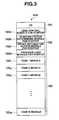
- FIG. 2 is a schematic diagram showing a data storing structure of the aforementioned flash memory 41.
- the flash memory 41 is storage means, and a lens information area 41a, a program area 41b, and memory area 41c for various data are ensured therein.
- device information which is the data acquired at the stage of factory shipping of the electronic still camera, and which shows the device performance of the lens group 11 (the zoom lens and the focus lens), and which is the adjustment data which is indispensable for controlling those, is stored.
- device information of the image pickup system of the CCD 31, white balance characteristic, or the like, as well, are stored.
- an OS which is indispensable for the operation of the CPU 5 and a startup program 102 comprising a lens control module 102a for startup, a starting factor determining module 102b for startup, a device information access module 102c for startup, and a program load module 102d for startup, which will be described later and are required for startup processings, are stored in a sequential order, and continuously, a main program 103 formed from a plurality of task modules 103 1 , 103 2 , ...
- the OS 101 and the startup program 102 are a program for startup, and the program for startup and the main program 103 correspond to a control program.
- the memory area 41c is an area which is managed by a file system configured by the CPU 5 after the startup of the OS, and various data which are read from the CPU 5 as needed and which are other than the above-described data are stored thereat. At this area, arbitrary data including image data as well are stored as needed.
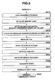
- FIGS. 4 and 5 show the concrete processing procedures of the CPU 5 at the time of startup accompanying an ON-operation of the power switch.
- the CPU 5 loads only the OS 101 and the startup program 102 from the program area 41b of the flash memory 41 by bootstrap loader, and expands those in the internal memory (step SA1), and thereafter, the CPU 5 starts up the OS (step SA2).
- the bootstrap loader is a small program which is read for loading the program, and is to be automatically accessed by the CPU 5 at the same time of the startup, and is stored in a predetermined address area (other than the memory area 41c) of the flash memory 41. Thereafter, the CPU 5 processes root tasks from step SA3 up to step SA24 on the basis of the startup program 102.
- step SA3 Setting of hardware such as an initialization of a port or the like is carried out (step SA3), and setting of an optical system interrupt handler, i.e., setting of interrupt processing required for the control of the lens group 11 is carried out (step SA4).
- a state signal is received from the sub-CPU of the key input unit 8, and a determination of a starting factor is carried out (step SA5).
- the mode state which has been set is a recording mode for photographing or another mode other than the recording mode, such as a playback mode for displaying a recorded image or the like.
- the difference between the recording mode and the playback mode is whether or not a lens is required to be protruded when the power is turned on.
- the lens is required to be protruded when the power is turned on.
- the power supply of the optical system such as the lens block 1, the driver block 2, and the lens control block 43 is controlled so as to be turned on (step SA6), and device information is loaded from the flash memory 41 (step SA7). It is determined whether high-speed startup is carried out or normal startup is carried out on the basis of the determined results of the starting factor acquired in step SA5 (step SA8).
- the mode which has been set is the recording mode, it is determined as the high-speed startup, and when the mode is another mode other than it, it is determined as the normal startup.
- step SA15 When the starting factor is the normal startup, the processings of the following steps SA9 to SA14 are not carried out, loading of the main program 103 which is the remaining control program is immediately started (step SA15).
- step SA9 a predetermined time (for example, 30 ms or less) until the time when a voltage of the optical system started to be supplied in step SA6 rises a steady-state voltage is waited for (step SA9), and an initialization of the hardware in the lens control block 43 is carried out (step SA10).
- the shutter actuator 17 is made to start shutter open of the mechanical shutter (step SA11), a battery voltage is checked at this point in time, and it is determined whether or not the battery voltage exceeds a predetermined voltage (step SA12). Note that, some waiting-for processings are carried out during from the time when the shutter open of the mechanical shutter is started to the time of the check for the battery voltage.
- the voltage value is the predetermined value or less, and it is determined as "No Battery,” the processings of the following steps SA13 and SA14 are not carried out, loading of the main program 103 which is the remaining control program is immediately started (step SA15).
- step SA13 a check and an initialization of the adjustment data for the zoom lens and the focus lens among the device information loaded in step SA7 are carried out (step SA13), and the protrusion (zoom-open) of the zoom lens for an initialization of the lens group 11 is made to start (step SA14).
- FIG. 6 is a schematic diagram showing the relationship between types of the interrupts for startup and operational items realized by the respective interrupts, and the zoom-open processing is achieved by ADC, MOTOR (ZOOM), edge (pulse), and timer interrupts.
- the ADC interrupt carries out analog-to-digital conversion with respect to the detected value from a photo interrupter (or photoelectric sensor, not shown) provided at the camera body, and outputs the value.
- the MOTOR (ZOOM) interrupt controls an output of the zoom motor 14.
- the edge (pulse) interrupt detects a moving amount of the zoom lens by counting of the number of pulses.
- Timer interrupt performs a time count and a timing adjustment and realizes a shutter-open processing.
- FIG. 7 is a flowchart showing the zoom-open processing (step SA14 of FIG. 4).
- a zoom correction value i.e., a moving amount up to a target position to which the zoom lens is protruded is calculated on the basis of the device information (step SB1).
- Confirmation of housing of the lens group 11 is carried out (step SB2).
- the confirmation is carried out by confirming whether a detected level (PR output) due to the ADC interrupt is "H” or "L.”
- step SB4 the confirmation of detecting of the PR output is continued, and it is determined whether the zoom lens is released from the state of being housed or not (steps SB4, SB5).
- step SB6 moving amount of the zoom lens is once reset
- step SB7 moving pulses (edge pulses) are counted one by one (step SB7).
- step SB9 driving of the zoom lens is stopped
- step SB10 driving processing is completed.
- step SB2 when the state of the zoom lens being housed cannot be confirmed (NO in step SB2), when it cannot be confirmed that the zoom lens is released from the state of being housed, and when the moving pulses cannot be counted, the driving of the zoom lens is stopped due to error processing, processing NG is set and reported to the outside (steps SB11 to SB14), and the driving processing is completed.
- step SA14 Immediately after the above-described zoom-open processing (step SA14) of the zoom lens is started, the CPU 5 starts loading of the remaining program (step SA15). Namely, without the end of the zoom-open operation of the lens group 11 being waited for, the main program 103 is loaded simultaneously.
- an initialization of the hardware i.e., a memory card of the image recording unit 42, a message buffer, the DRAM 6 or the like (steps SA16, SA17), checking of the remaining data of the device information (other than the adjustment data of the zoom lens and the focus lens), and an initialization of the CCD image pickup system block 3 by using those data (step SA18), and initializations of an LED and the display system (steps SA19, SA20) are carried out.
- initializations of the software i.e., initialization of the sub-CPU (various settings) and an initialization of a memory manager are carried out (steps SA21, SA22).
- step SA5 Some of initializations of the sub-CPU are already carried out at the time of the determination of a starting factor in step SA5. After the respective tasks realizing various operations in the main program 103 which completed loading are generated (step SA23), the termination processing of the root task is carried out (step SA24). After these processings, the memory area 41c becomes a usable state.
- the routine proceeds to execution of processings corresponding to the respective modes for recording and playback in the same way as in the normal processing based on the processings of the plurality of tasks generated (step SA25).
- the CPU 5 executes various initializing processings such as an initialization of the iris, initializations of the image pickup system of the CCD 31, white balance characteristic, or the like, an initialization of focus control, a preparation for displaying of a through image on the image display unit 7, or the like.
- initializing operation in which the lens group 11 is zoomed open is immediately started, and during the time, operations required for the other initializations are simultaneously carried out. Accordingly, a starting time required for photographing in the configuration having movable lens 11 can be markedly reduced, and speedup of the starting time is possible.
- a minimum number of programs required to initialize the optical system are first loaded and the initialization of the optical system is prioritized. Thus, the time from the power is turned on until the lens is protruded is shortened. These minimum number of programs are performed by an interrupt processing not by the normal task so that a task preparation time is not needed.
- the startup program 102 and the main program 103 are divided and loaded, and a zoom-open operation of the lens group 11 is carried out on the basis of the startup program 102, the zoom-open operation of the lens group 11 can be started in an early stage. Speedup of the starting time is possible thereby as well.
- the main program 103 is read simultaneously with the zoom-open operation of the lens group 11, an operating time required for the initializing operations other than the zoom-open operation of the lens group 11 can be shortened. Speedup of the starting time is possible thereby as well.
- the startup program 102 and the main program 103 are collectively loaded, or such that some of the startup program 102 and the main program 103 are loaded.
- it may be configured such that the startup program 102 and the main program 103 are collectively loaded, or such that some of the startup program 102 and the main program 103 are loaded.
- the startup program 102 can be efficiently divided and loaded. Accordingly, efficiency of the processing at the time of startup can be improved, and speedup of the starting time is possible thereby as well.
- driving means for driving the optical system
- control unit for making the driving means start driving to a predetermined position by an initialization of the optical system, before the other initializations than the initialization of the optical system, at the time of startup in a state in which an operation mode for photographing is set.
- control unit reads a program for startup which is required for the initialization of the optical system included in the control program from the storage means. After the driving means is made to start driving of the optical system by an execution of the startup program, the control unit reads a control program except for the program for startup, from the storage means.
- the program for startup which is required for the initialization of the optical system is read separately from the programs required for the initializations other than the initialization of the optical system, the initialization of the optical system at the time of startup can be started in an early stage.
- the control unit reads the control program except for the program for startup from the storage means without waiting for the end of the driving to the predetermined position by the initialization of the optical system.
- control programs are stored continuously after the program for startup in the storage means.
- control program can be efficiently divided and read.
- a method for starting the camera device having a movable optical system comprises a step of determining whether an operating mode for photographing is set or not, and a step of making the driving means start driving to a predetermined position by an initialization, before other initializations than the initialization of the optical system, when the operating mode for photographing is set.
- a program for a computer controlling a camera device having a movable optical system and driving means for driving the optical system makes the computer as control unit for making the driving means start driving to a predetermined position by an initialization of the optical system, before the other initializations than the initialization of the optical system, at the time of startup in a state in which the operating mode for photographing is set.
- the present invention can be practiced as a computer readable recording medium in which a program for allowing the computer to function as predetermined means, allowing the computer to realize a predetermined function, or allowing the computer to conduct predetermined means.
Abstract
Description
- The present invention relates to a camera device having a movable optical system, and a method and a program for starting the camera device.
- Conventionally, in electronic still cameras or digital cameras, an object is picked up by an image pickup element such as a CCD or the like, and while the image is being displayed as a through image on a liquid crystal display device, the picked-up image is recorded as digital data on a recording medium such as a memory card or the like in accordance with an operation of a shutter. Accordingly, at the time of startup when the power supply of an electronic still camera is turned on for photographing, various initializing operations with respect to both of the hardware and the software, for example, such as a preparation for making data to be able to be recorded on a recording medium, a preparation for image picking-up an object, and a preparation for displaying the picked-up image, are indispensable. As a time from the power-on until when it is in a state in which photographing is available, a given starting time which is longer than that in the case of a silver salt camera or an analog camera is required. Therefore, there is the shortcoming that the electronic still cameras or the digital cameras cannot cope with an urgent chance to press a shutter key.
- Therefore, in order to make shortening of the above-described starting time to be possible, a conventional example in which a time of reading management information from an freely attachable and detachable memory card is omitted is disclosed in paragraph 0025 of Japanese Patent Application KOKAI Publication No. 2002-237977.
- However, in an electronic still camera, which has a movable or sinkable optical system in which a lens is housed in a camera housing during non-photographing and it is necessary to protrude the zoom lens prior to photographing, the time required for protruding the optical system accounts for most of the starting time. Therefore, even if the time of reading management information from a memory card is omitted as in the conventional document, the time accounts for extremely small percentage of the total starting time, and there is the problem that an effect on reduction in starting time has not been satisfactory yet.
- The present invention has been achieved in consideration of the conventional problem, and an object of the present invention is to provide a camera device which can reduce the starting time in an electronic still camera having a movable optical system, a method for starting the camera device, and a program used for realizing those.
- According to an embodiment of the present invention, a camera device comprises an optical system, a driving unit which drives the optical system, and a control unit which makes the driving unit start driving of the optical system to a predetermined state by an initialization of the optical system, before other initializations than the initialization of the optical system, when the camera device is started up in a state in which an operation mode for photographing is set.
- This summary of the invention does not necessarily describe all necessary features so that the invention may also be a sub-combination of these described features.
- The invention can be more fully understood from the following detailed description when taken in conjunction with the accompanying drawings, in which:
- FIG. 1 is a block diagram schematically illustrating an electronic still camera showing an embodiment of the present invention;
- FIG. 2 is a schematic diagram showing a data storing structure of a flash memory in the electronic still camera of the embodiment;
- FIG. 3 is a schematic diagram showing stored data at a program area of the flash memory;
- FIG. 4 is a former part of a flowchart showing a processing procedure of a CPU at the time of startup of the electronic still camera of the embodiment;
- FIG. 5 is a latter part of the flowchart showing the processing procedure of the CPU at the time of startup of the electronic still camera;
- FIG. 6 is a schematic diagram showing relationships between types of startup interrupts and operational items realized by the respective interrupts; and
- FIG. 7 is a flowchart showing a zoom-open processing of the embodiment.
-
- An embodiment of a camera device according to the present invention will now be described with reference to the accompanying drawings. FIG. 1 is a block diagram illustrating an electrical configuration of an electronic still camera showing the embodiment of the present invention.
- The electronic still camera has a zooming function and an automatic focusing function, and has a
lens block 1 for realizing the functions. Thelens block 1 comprises amovable lens group 11 including a zoom lens and a focus lens which are movably arranged in the direction of an optical axis,position detecting sensors lens group 11, azoom motor 14 for moving the zoom lens and afocus motor 15 for moving the focus lens, anactuator 16 for an iris which opens and closes an iris (not shown), and anactuator 17 for a shutter which opens and closes a mechanical shutter. The above-described respective motors andactuators 14 to 17 are driven byvarious drivers 18 to 21, for zooming, for focusing, for an iris, and for a shutter, which are provided at adriver block 2. Therespective motors actuators 14 to 17, and thedriver block 2 configure driving means. - The electronic still camera has a CCD image-
pickup system block 3 including mainly aCCD 31 which is an image pickup element arranged at the rear side of the photographing optical axis of thelens group 11, a CDS (Correlated Double Sampling)/AD conversion block 32, and a TG (Timing Generator) 33. When the electronic still camera is set to a recording mode for photographing, theCCD 31 photoelectric-converts an optical image of an object which is formed by thelens group 11, and outputs, each given cycle, one photoelectric-converted output screen by being scanning-driven by theTG 33. The CDS/AD block 32 carries out noise elimination due to correlated double sampling and conversion into a digital signal with respect to an output analog signal whose gain has been appropriately adjusted for each of the color components of RGB by an amplifier (not shown) after being output from theCCD 31, and outputs the signal as an image pickup signal to a color process circuit 4. - The color process circuit 4 performs color process processing including pixel interpolation processing to the input image pickup signal, generates digital-valued luminance signal (Y) and color-difference signals (Cb, Cr), and outputs the signals to a
CPU 5 serving as control unit for controlling the entire electronic still camera. TheCPU 5 comprises a microprocessor having an internal memory, various arithmetic processing circuits, an I/O interface for data, and the like. - The digital signal (image signal) transmitted to the
CPU 5 is temporarily stored in aDRAM 6 and transmitted to an image display unit 7. The image display unit 7 includes a video encoder, a VRAM, a liquid crystal monitor, and a driving circuit thereof, and generates a video signal based on the transmitted video signal by the video encoder, and a display image based on the video signal, i.e., a through image of the object picked up by theCCD 31 is displayed on the liquid crystal monitor. - A
key input unit 8 comprises various keys such as a power key, a recording/playback mode change-over switch, a shutter key, a menu key, or the like, and a sub-CPU which receives input therefrom and transmits an operation signal corresponding thereto to theCPU 5. The sub-CPU transmits a state signal showing a state of the mode change-over switch, i.e., a mode setting state as needed. When the shutter key is pressed down in the aforementioned recording mode, a trigger signal (operation signal) is output from thekey input unit 8 to theCPU 5. - When the trigger signal is input, the
CPU 5 reads out, for each of the components of Y, Cb, Cr and in basic units called basic blocks which are 8 pixels (vertical) × 8 pixels (horizontal), the image data of one screen fetched from theCCD 31 at that point in time, and writes the image data into aJPEG circuit 9. TheJPEG circuit 9 carries out DCT (Discrete Cosine Transform) and coding. The compressed one-image data compressed by theJPEG circuit 9 is stored in animage recording unit 42. Theimage recording unit 42 comprises a card interface, and nonvolatile various memory cards which are connected to theCPU 5 via the card interface, and which are mounted so as to be freely attachable and detachable on a camera body. - In the recording mode for photographing, the
CPU 5 makes alens control block 43 generate driving signals to be transmitted to thevarious drivers 18 to 21 of thedriver block 2 on the basis of various programs stored in a rewritablenonvolatile flash memory 41, the aforementioned operation signal from thekey input unit 8, or the like, and controls the position controls of the zoom lens and focus lens, an opening of the iris, and the opening and closing action of the mechanical shutter. Positional information of the lens detected by theposition detecting sensors CPU 5 via thelens control block 43. - On the other hand, the image data recorded in the
image recording unit 42 is read by theCPU 5 in the playback mode for displaying the recorded image, transmitted to the image display unit 7 after being expanded by theJPEG circuit 9, and displayed on the liquid crystal monitor. - FIG. 2 is a schematic diagram showing a data storing structure of the
aforementioned flash memory 41. Theflash memory 41 is storage means, and alens information area 41a, aprogram area 41b, andmemory area 41c for various data are ensured therein. At thelens information area 41a, device information which is the data acquired at the stage of factory shipping of the electronic still camera, and which shows the device performance of the lens group 11 (the zoom lens and the focus lens), and which is the adjustment data which is indispensable for controlling those, is stored. Moreover, at thelens information area 41a, device information of the image pickup system of theCCD 31, white balance characteristic, or the like, as well, are stored. - At the
program area 41b, programs required for the control the aforementioned respective portions by theCPU 5, and various data required for the control are stored. In the present embodiment, as one example, as shown in FIG. 3, at the head portion of theprogram area 41b, an OS (Operating System) 101 which is indispensable for the operation of theCPU 5 and astartup program 102 comprising alens control module 102a for startup, a startingfactor determining module 102b for startup, a deviceinformation access module 102c for startup, and aprogram load module 102d for startup, which will be described later and are required for startup processings, are stored in a sequential order, and continuously, amain program 103 formed from a plurality oftask modules startup program 102 are a program for startup, and the program for startup and themain program 103 correspond to a control program. - The
memory area 41c is an area which is managed by a file system configured by theCPU 5 after the startup of the OS, and various data which are read from theCPU 5 as needed and which are other than the above-described data are stored thereat. At this area, arbitrary data including image data as well are stored as needed. - Next, operations according to the present embodiment of the electronic still camera comprising the above-described configuration will be described in accordance with FIGS. 4 to 7. Flowcharts of FIGS. 4 and 5 show the concrete processing procedures of the
CPU 5 at the time of startup accompanying an ON-operation of the power switch. - After the
CPU 5 is started up accompanying power-on, theCPU 5 loads only theOS 101 and thestartup program 102 from theprogram area 41b of theflash memory 41 by bootstrap loader, and expands those in the internal memory (step SA1), and thereafter, theCPU 5 starts up the OS (step SA2). The bootstrap loader is a small program which is read for loading the program, and is to be automatically accessed by theCPU 5 at the same time of the startup, and is stored in a predetermined address area (other than thememory area 41c) of theflash memory 41. Thereafter, theCPU 5 processes root tasks from step SA3 up to step SA24 on the basis of thestartup program 102. - Setting of hardware such as an initialization of a port or the like is carried out (step SA3), and setting of an optical system interrupt handler, i.e., setting of interrupt processing required for the control of the
lens group 11 is carried out (step SA4). A state signal is received from the sub-CPU of thekey input unit 8, and a determination of a starting factor is carried out (step SA5). Here, it is determined whether the mode state which has been set is a recording mode for photographing or another mode other than the recording mode, such as a playback mode for displaying a recorded image or the like. The difference between the recording mode and the playback mode is whether or not a lens is required to be protruded when the power is turned on. If the operation mode is the recording mode, the lens is required to be protruded when the power is turned on. The power supply of the optical system such as thelens block 1, thedriver block 2, and thelens control block 43 is controlled so as to be turned on (step SA6), and device information is loaded from the flash memory 41 (step SA7). It is determined whether high-speed startup is carried out or normal startup is carried out on the basis of the determined results of the starting factor acquired in step SA5 (step SA8). When the mode which has been set is the recording mode, it is determined as the high-speed startup, and when the mode is another mode other than it, it is determined as the normal startup. - When the starting factor is the normal startup, the processings of the following steps SA9 to SA14 are not carried out, loading of the
main program 103 which is the remaining control program is immediately started (step SA15). - On the other hand, when the starting factor is the high-speed startup, a predetermined time (for example, 30 ms or less) until the time when a voltage of the optical system started to be supplied in step SA6 rises a steady-state voltage is waited for (step SA9), and an initialization of the hardware in the
lens control block 43 is carried out (step SA10). Theshutter actuator 17 is made to start shutter open of the mechanical shutter (step SA11), a battery voltage is checked at this point in time, and it is determined whether or not the battery voltage exceeds a predetermined voltage (step SA12). Note that, some waiting-for processings are carried out during from the time when the shutter open of the mechanical shutter is started to the time of the check for the battery voltage. Here, when the voltage value is the predetermined value or less, and it is determined as "No Battery," the processings of the following steps SA13 and SA14 are not carried out, loading of themain program 103 which is the remaining control program is immediately started (step SA15). - On the other hand, when the voltage value exceeds the predetermined value, and it is determined as "Battery OK," a check and an initialization of the adjustment data for the zoom lens and the focus lens among the device information loaded in step SA7 are carried out (step SA13), and the protrusion (zoom-open) of the zoom lens for an initialization of the
lens group 11 is made to start (step SA14). - Here, the zoom-open processing of the zoom lens will be described. The processing is carried out by the interrupt for startup which is prepared in the lens control module for startup of the
startup program 102. FIG. 6 is a schematic diagram showing the relationship between types of the interrupts for startup and operational items realized by the respective interrupts, and the zoom-open processing is achieved by ADC, MOTOR (ZOOM), edge (pulse), and timer interrupts. The ADC interrupt carries out analog-to-digital conversion with respect to the detected value from a photo interrupter (or photoelectric sensor, not shown) provided at the camera body, and outputs the value. The MOTOR (ZOOM) interrupt controls an output of thezoom motor 14. The edge (pulse) interrupt detects a moving amount of the zoom lens by counting of the number of pulses. Timer interrupt performs a time count and a timing adjustment and realizes a shutter-open processing. - FIG. 7 is a flowchart showing the zoom-open processing (step SA14 of FIG. 4). A zoom correction value, i.e., a moving amount up to a target position to which the zoom lens is protruded is calculated on the basis of the device information (step SB1). Confirmation of housing of the
lens group 11 is carried out (step SB2). The confirmation is carried out by confirming whether a detected level (PR output) due to the ADC interrupt is "H" or "L." - Thereafter, driving of the zoom lens by the MOTOR (ZOOM) interrupt and the timer interrupt are started (step SB3).
- At the beginning, the confirmation of detecting of the PR output is continued, and it is determined whether the zoom lens is released from the state of being housed or not (steps SB4, SB5). When the zoom lens is released from the state of being housed (YES in step SB4), after a moving amount of the zoom lens is once reset (step SB6), moving pulses (edge pulses) are counted one by one (step SB7). When the zoom lens reaches the target position (e.g., a Wide end) in a short time (YES in step SB8), driving of the zoom lens is stopped (step SB9), the processing OK is set and reported to the outside (step SB10), and the driving processing is completed. Note that, on the way of the processing, when the state of the zoom lens being housed cannot be confirmed (NO in step SB2), when it cannot be confirmed that the zoom lens is released from the state of being housed, and when the moving pulses cannot be counted, the driving of the zoom lens is stopped due to error processing, processing NG is set and reported to the outside (steps SB11 to SB14), and the driving processing is completed.
- Immediately after the above-described zoom-open processing (step SA14) of the zoom lens is started, the
CPU 5 starts loading of the remaining program (step SA15). Namely, without the end of the zoom-open operation of thelens group 11 being waited for, themain program 103 is loaded simultaneously. - Continuously, an initialization of the hardware, i.e., a memory card of the
image recording unit 42, a message buffer, theDRAM 6 or the like (steps SA16, SA17), checking of the remaining data of the device information (other than the adjustment data of the zoom lens and the focus lens), and an initialization of the CCD imagepickup system block 3 by using those data (step SA18), and initializations of an LED and the display system (steps SA19, SA20) are carried out. Moreover, initializations of the software, i.e., initialization of the sub-CPU (various settings) and an initialization of a memory manager are carried out (steps SA21, SA22). Some of initializations of the sub-CPU are already carried out at the time of the determination of a starting factor in step SA5. After the respective tasks realizing various operations in themain program 103 which completed loading are generated (step SA23), the termination processing of the root task is carried out (step SA24). After these processings, thememory area 41c becomes a usable state. - Hereafter, the routine proceeds to execution of processings corresponding to the respective modes for recording and playback in the same way as in the normal processing based on the processings of the plurality of tasks generated (step SA25). Namely, the
CPU 5 executes various initializing processings such as an initialization of the iris, initializations of the image pickup system of theCCD 31, white balance characteristic, or the like, an initialization of focus control, a preparation for displaying of a through image on the image display unit 7, or the like. - As described above, in the present embodiment, when a recording mode is set when the device is started up by power-on, initializing operation (steps SA9 to SA14) in which the
lens group 11 is zoomed open is immediately started, and during the time, operations required for the other initializations are simultaneously carried out. Accordingly, a starting time required for photographing in the configuration havingmovable lens 11 can be markedly reduced, and speedup of the starting time is possible. Instead of initializing the optical system after all the programs are loaded, a minimum number of programs required to initialize the optical system are first loaded and the initialization of the optical system is prioritized. Thus, the time from the power is turned on until the lens is protruded is shortened. These minimum number of programs are performed by an interrupt processing not by the normal task so that a task preparation time is not needed. - Further, in the present embodiment, because the
startup program 102 and themain program 103 are divided and loaded, and a zoom-open operation of thelens group 11 is carried out on the basis of thestartup program 102, the zoom-open operation of thelens group 11 can be started in an early stage. Speedup of the starting time is possible thereby as well. - Moreover, because, without the end of the zoom-open operation of the
lens group 11 started being waited for, themain program 103 is read simultaneously with the zoom-open operation of thelens group 11, an operating time required for the initializing operations other than the zoom-open operation of thelens group 11 can be shortened. Speedup of the starting time is possible thereby as well. - Note that, differently from the present embodiment, it may be configured such that the
startup program 102 and themain program 103 are collectively loaded, or such that some of thestartup program 102 and themain program 103 are loaded. In this case as well, in the same way as in the present embodiment, by simultaneously carrying out the operations required for other initializations except for the zoom-open operation of thelens group 11 during the time when the zoom-open operation of thelens group 11 is being carried out, speedup of the starting time is possible. - Further, as in the present embodiment, even if the device is a type in which the
flash memory 41 cannot carry out random-access, due to theOS 101, thestartup program 102, and themain program 103 being serially stored in theflash memory 41, thestartup program 102 can be efficiently divided and loaded. Accordingly, efficiency of the processing at the time of startup can be improved, and speedup of the starting time is possible thereby as well. - In accordance with the embodiment of the present invention, in a camera device having a movable optical system, driving means for driving the optical system, and control unit for making the driving means start driving to a predetermined position by an initialization of the optical system, before the other initializations than the initialization of the optical system, at the time of startup in a state in which an operation mode for photographing is set, are provided.
- Therefore, at the time of startup in a state in which an operation mode for photographing is set, a mechanical initializing operation which is such that the optical system is driven (zoomed open) to a predetermined position, and operations required for the other initializations can be simultaneously carried out.
- Moreover, storage means for storing a control program required for the control of the camera device is further provided, and the control unit reads a program for startup which is required for the initialization of the optical system included in the control program from the storage means. After the driving means is made to start driving of the optical system by an execution of the startup program, the control unit reads a control program except for the program for startup, from the storage means.
- Therefore, because the program for startup which is required for the initialization of the optical system is read separately from the programs required for the initializations other than the initialization of the optical system, the initialization of the optical system at the time of startup can be started in an early stage.
- The control unit reads the control program except for the program for startup from the storage means without waiting for the end of the driving to the predetermined position by the initialization of the optical system.
- Therefore, by reading the programs required for the initializations except for the initialization of the optical system on the way of the initialization of the optical system, an operating time required for the initializing operations other than that of the optical system can be shortened.
- Further, the other control programs are stored continuously after the program for startup in the storage means.
- Therefore, even in a configuration in which the storage means for storing the control program cannot carry out random-access, the control program can be efficiently divided and read.
- Furthermore, in accordance with another embodiment of the present invention, a method for starting the camera device having a movable optical system comprises a step of determining whether an operating mode for photographing is set or not, and a step of making the driving means start driving to a predetermined position by an initialization, before other initializations than the initialization of the optical system, when the operating mode for photographing is set.
- Therefore, at the time of startup in a state in which the operation mode for photographing is set, during the time when a mechanical initializing operation which is such that the optical system is driven (zoomed open) to a predetermined position is being carried out, and the other initializing operations required for the other initializations can be simultaneously carried out.
- In addition, in accordance with yet another embodiment of the present invention, a program for a computer controlling a camera device having a movable optical system and driving means for driving the optical system makes the computer as control unit for making the driving means start driving to a predetermined position by an initialization of the optical system, before the other initializations than the initialization of the optical system, at the time of startup in a state in which the operating mode for photographing is set.
- Therefore, at the time of startup in a state in which the operation mode for photographing is set, during the time when a mechanical initializing operation which is such that the optical system is driven (zoomed open) to a predetermined position is being carried out, and the other initializing operations can be simultaneously carried out.
- While the description above refers to particular embodiments of the present invention, it will be understood that many modifications may be made without departing from the spirit thereof. The accompanying claims are intended to cover such modifications as would fall within the true scope and spirit of the present invention. The presently disclosed embodiments are therefore to be considered in all respects as illustrative and not restrictive, the scope of the invention being indicated by the appended claims, rather than the foregoing description, and all changes that come within the meaning and range of equivalency of the claims are therefore intended to be embraced therein. For example, the present invention can be practiced as a computer readable recording medium in which a program for allowing the computer to function as predetermined means, allowing the computer to realize a predetermined function, or allowing the computer to conduct predetermined means.
Claims (10)
- A camera device comprising:an optical system (1); anddriving means (2) for driving the optical system (1), characterized by further comprising:control means (5) for making the driving means (2) start driving of the optical system (1) to a predetermined state by an initialization of the optical system (1), before other initializations than the initialization of the optical system (1), when the camera device is started up in a state in which an operation mode for photographing is set.
- The camera device according to claim 1, characterized by further comprising a memory (41) which stores a control program for the camera device, and
characterized in that the control means (5) reads a program for startup which is required for the initialization of the optical system (1) from the memory (41) and reads a control program other than the program for startup from the memory (41) after making the driving means (2) start driving of the optical system (1) to the predetermined state by an execution of the program for startup. - The camera device according to claim 1, characterized in that the memory (41) stores other control programs continuously after the program for startup.
- The camera device according to claim 2, characterized in that the control means (5) reads the control program except for the program for startup from the memory (41) without waiting for an end of the driving of the optical system to the predetermined state.
- The camera device according to claim 4, characterized in that the memory (41) stores other control programs continuously after the program for startup.
- The camera device according to claim 1, characterized in that said optical system (1) comprises a sinkable lens.
- A method for starting a camera device comprising an optical system, the method characterized by comprising:determining whether or not the an operation mode for photographing is set; andstarting driving of the optical system to a predetermined state by an initialization of the optical system, before other initializations than the initialization of the optical system, when it is determined that the operation mode for photographing is set.
- The method according to claim 7, characterized in that said optical system comprises a sinkable lens.
- A computer program for a camera device comprising an optical system and a driving means which drives the optical system, the program being stored in a computer readable medium, and the program characterized by comprising:determining whether or not the an operation mode for photographing is set; andstarting driving of the optical system to a predetermined state by an initialization of the optical system, before other initializations than the initialization of the optical system, when it is determined that the operation mode for photographing is set.
- The computer program according to claim 9, characterized in that said optical system comprises a sinkable lens.
Applications Claiming Priority (2)
| Application Number | Priority Date | Filing Date | Title |
|---|---|---|---|
| JP2003048062 | 2003-02-25 | ||
| JP2003048062A JP4026511B2 (en) | 2003-02-25 | 2003-02-25 | Camera device |
Publications (2)
| Publication Number | Publication Date |
|---|---|
| EP1452971A1 true EP1452971A1 (en) | 2004-09-01 |
| EP1452971B1 EP1452971B1 (en) | 2008-08-20 |
Family
ID=32767741
Family Applications (1)
| Application Number | Title | Priority Date | Filing Date |
|---|---|---|---|
| EP04004265A Expired - Fee Related EP1452971B1 (en) | 2003-02-25 | 2004-02-25 | Fast start-up program for camera |
Country Status (7)
| Country | Link |
|---|---|
| US (1) | US7477288B2 (en) |
| EP (1) | EP1452971B1 (en) |
| JP (1) | JP4026511B2 (en) |
| KR (1) | KR100634555B1 (en) |
| CN (1) | CN1263287C (en) |
| DE (1) | DE602004015871D1 (en) |
| TW (1) | TWI256247B (en) |
Families Citing this family (7)
| Publication number | Priority date | Publication date | Assignee | Title |
|---|---|---|---|---|
| JP3861828B2 (en) * | 2003-02-26 | 2006-12-27 | カシオ計算機株式会社 | Camera device, camera device activation method, and program |
| JP2004258546A (en) * | 2003-02-27 | 2004-09-16 | Casio Comput Co Ltd | Camera, its start method and program |
| JP2004264418A (en) * | 2003-02-28 | 2004-09-24 | Casio Comput Co Ltd | Camera system, method for actuating camera system, and program |
| KR100755705B1 (en) | 2006-02-08 | 2007-09-05 | 삼성전자주식회사 | Apparatus and method for photographing by a camera |
| EP1944690A3 (en) * | 2006-12-19 | 2009-05-20 | Continental Automotive GmbH | Method, device and system |
| JP5769908B1 (en) * | 2014-10-10 | 2015-08-26 | オリンパス株式会社 | Imaging apparatus, imaging system, imaging apparatus activation method, and program |
| US10230888B2 (en) | 2015-07-31 | 2019-03-12 | Qualcomm Incorporated | Sensor-based camera initialization |
Citations (5)
| Publication number | Priority date | Publication date | Assignee | Title |
|---|---|---|---|---|
| EP1083740A2 (en) * | 1999-09-08 | 2001-03-14 | Casio Computer Co., Ltd. | Electronic still camera capable of removing noise component in image data and signal processing method thereof |
| US20010007472A1 (en) * | 2000-01-11 | 2001-07-12 | Tomoyuki Nishimura | Lens moving mechanism for an imaging device and method thereof |
| US20010009443A1 (en) * | 2000-01-25 | 2001-07-26 | Kazunori Suemoto | Digital camera |
| US6470413B1 (en) * | 1996-07-19 | 2002-10-22 | Canon Kabushiki Kaisha | Information processing apparatus and method in which an executable file in an incorporated memory is loaded and executed at startup |
| US20020171755A1 (en) * | 2001-05-18 | 2002-11-21 | Fuji Photo Film Co., Ltd. | Digital camera changeable operation sequence |
Family Cites Families (17)
| Publication number | Priority date | Publication date | Assignee | Title |
|---|---|---|---|---|
| CA1212461A (en) | 1982-10-29 | 1986-10-07 | Rca Corporation | Signal sampling circuit |
| JP3513164B2 (en) * | 1992-07-09 | 2004-03-31 | キヤノン株式会社 | Lens control device |
| US5819120A (en) * | 1995-11-28 | 1998-10-06 | Fuji Photo Film Co., Ltd. | Variable focus lens device in camera |
| JPH11167160A (en) * | 1997-09-30 | 1999-06-22 | Fuji Photo Optical Co Ltd | Camera |
| TW403864B (en) | 1997-10-08 | 2000-09-01 | Sony Corp | Program startup apparatus and program startup method for use in electronic machine, and medium |
| JP3817861B2 (en) * | 1997-10-14 | 2006-09-06 | コニカミノルタフォトイメージング株式会社 | Zoom lens position detection device |
| US6212632B1 (en) * | 1998-07-31 | 2001-04-03 | Flashpoint Technology, Inc. | Method and system for efficiently reducing the RAM footprint of software executing on an embedded computer system |
| JP4164202B2 (en) * | 1998-10-08 | 2008-10-15 | キヤノン株式会社 | Electronic device, driving method of electronic device, and computer-readable storage medium |
| US6401202B1 (en) * | 1999-06-18 | 2002-06-04 | Phoenix Technologies Ltd. | Multitasking during BIOS boot-up |
| US6487656B1 (en) * | 1999-12-10 | 2002-11-26 | Phoenix Technologies Ltd. | System and method for providing functionalities to system BIOS |
| JP2001268413A (en) | 2000-03-15 | 2001-09-28 | Toshiba Corp | Digital camera device |
| KR100378594B1 (en) | 2000-07-31 | 2003-03-31 | 한국전자통신연구원 | Camera Auto-Focusing Method And Apparatus Using Wavelet Transform |
| US6766474B2 (en) * | 2000-12-21 | 2004-07-20 | Intel Corporation | Multi-staged bios-based memory testing |
| JP4499935B2 (en) | 2001-02-07 | 2010-07-14 | オリンパス株式会社 | Electronic camera |
| JP3861828B2 (en) * | 2003-02-26 | 2006-12-27 | カシオ計算機株式会社 | Camera device, camera device activation method, and program |
| JP2004258546A (en) * | 2003-02-27 | 2004-09-16 | Casio Comput Co Ltd | Camera, its start method and program |
| JP2004264418A (en) * | 2003-02-28 | 2004-09-24 | Casio Comput Co Ltd | Camera system, method for actuating camera system, and program |
-
2003
- 2003-02-25 JP JP2003048062A patent/JP4026511B2/en not_active Expired - Fee Related
-
2004
- 2004-02-23 US US10/785,534 patent/US7477288B2/en active Active
- 2004-02-24 TW TW093104525A patent/TWI256247B/en not_active IP Right Cessation
- 2004-02-24 KR KR1020040012084A patent/KR100634555B1/en active IP Right Grant
- 2004-02-25 CN CNB2004100302366A patent/CN1263287C/en not_active Expired - Fee Related
- 2004-02-25 EP EP04004265A patent/EP1452971B1/en not_active Expired - Fee Related
- 2004-02-25 DE DE602004015871T patent/DE602004015871D1/en not_active Expired - Lifetime
Patent Citations (5)
| Publication number | Priority date | Publication date | Assignee | Title |
|---|---|---|---|---|
| US6470413B1 (en) * | 1996-07-19 | 2002-10-22 | Canon Kabushiki Kaisha | Information processing apparatus and method in which an executable file in an incorporated memory is loaded and executed at startup |
| EP1083740A2 (en) * | 1999-09-08 | 2001-03-14 | Casio Computer Co., Ltd. | Electronic still camera capable of removing noise component in image data and signal processing method thereof |
| US20010007472A1 (en) * | 2000-01-11 | 2001-07-12 | Tomoyuki Nishimura | Lens moving mechanism for an imaging device and method thereof |
| US20010009443A1 (en) * | 2000-01-25 | 2001-07-26 | Kazunori Suemoto | Digital camera |
| US20020171755A1 (en) * | 2001-05-18 | 2002-11-21 | Fuji Photo Film Co., Ltd. | Digital camera changeable operation sequence |
Also Published As
| Publication number | Publication date |
|---|---|
| CN1525745A (en) | 2004-09-01 |
| EP1452971B1 (en) | 2008-08-20 |
| DE602004015871D1 (en) | 2008-10-02 |
| KR20040076615A (en) | 2004-09-01 |
| TW200425723A (en) | 2004-11-16 |
| US20040165073A1 (en) | 2004-08-26 |
| CN1263287C (en) | 2006-07-05 |
| KR100634555B1 (en) | 2006-10-16 |
| US7477288B2 (en) | 2009-01-13 |
| JP2004258248A (en) | 2004-09-16 |
| TWI256247B (en) | 2006-06-01 |
| JP4026511B2 (en) | 2007-12-26 |
Similar Documents
| Publication | Publication Date | Title |
|---|---|---|
| EP1452972B1 (en) | Fast start-up program for camera | |
| US20080181599A1 (en) | Camera device and method and program for starting the camera device | |
| US20090115871A1 (en) | Camera device and method and program for starting the camera device | |
| EP1452971B1 (en) | Fast start-up program for camera | |
| EP1916839B1 (en) | Image pickup apparatus and moving picture photographing method thereof | |
| JP4196696B2 (en) | Electronic camera, electronic camera activation method, and program | |
| JP4948011B2 (en) | Imaging apparatus, control method therefor, computer program, and storage medium | |
| JP2007310409A (en) | Camera device and program | |
| JP2004260608A (en) | Camera equipment, starting method thereof, and program | |
| JP4590421B2 (en) | Imaging apparatus and imaging method |
Legal Events
| Date | Code | Title | Description |
|---|---|---|---|
| PUAI | Public reference made under article 153(3) epc to a published international application that has entered the european phase |
Free format text: ORIGINAL CODE: 0009012 |
|
| 17P | Request for examination filed |
Effective date: 20040225 |
|
| AK | Designated contracting states |
Kind code of ref document: A1 Designated state(s): AT BE BG CH CY CZ DE DK EE ES FI FR GB GR HU IE IT LI LU MC NL PT RO SE SI SK TR |
|
| AX | Request for extension of the european patent |
Extension state: AL LT LV MK |
|
| 17Q | First examination report despatched |
Effective date: 20050317 |
|
| AKX | Designation fees paid |
Designated state(s): DE FR GB |
|
| RBV | Designated contracting states (corrected) |
Designated state(s): DE FR GB |
|
| GRAP | Despatch of communication of intention to grant a patent |
Free format text: ORIGINAL CODE: EPIDOSNIGR1 |
|
| GRAS | Grant fee paid |
Free format text: ORIGINAL CODE: EPIDOSNIGR3 |
|
| GRAA | (expected) grant |
Free format text: ORIGINAL CODE: 0009210 |
|
| AK | Designated contracting states |
Kind code of ref document: B1 Designated state(s): DE FR GB |
|
| REG | Reference to a national code |
Ref country code: GB Ref legal event code: FG4D |
|
| REF | Corresponds to: |
Ref document number: 602004015871 Country of ref document: DE Date of ref document: 20081002 Kind code of ref document: P |
|
| PLBE | No opposition filed within time limit |
Free format text: ORIGINAL CODE: 0009261 |
|
| STAA | Information on the status of an ep patent application or granted ep patent |
Free format text: STATUS: NO OPPOSITION FILED WITHIN TIME LIMIT |
|
| 26N | No opposition filed |
Effective date: 20090525 |
|
| REG | Reference to a national code |
Ref country code: FR Ref legal event code: PLFP Year of fee payment: 13 |
|
| REG | Reference to a national code |
Ref country code: FR Ref legal event code: PLFP Year of fee payment: 14 |
|
| REG | Reference to a national code |
Ref country code: FR Ref legal event code: PLFP Year of fee payment: 15 |
|
| PGFP | Annual fee paid to national office [announced via postgrant information from national office to epo] |
Ref country code: FR Payment date: 20210113 Year of fee payment: 18 |
|
| PGFP | Annual fee paid to national office [announced via postgrant information from national office to epo] |
Ref country code: GB Payment date: 20210217 Year of fee payment: 18 Ref country code: DE Payment date: 20210209 Year of fee payment: 18 |
|
| REG | Reference to a national code |
Ref country code: DE Ref legal event code: R119 Ref document number: 602004015871 Country of ref document: DE |
|
| GBPC | Gb: european patent ceased through non-payment of renewal fee |
Effective date: 20220225 |
|
| PG25 | Lapsed in a contracting state [announced via postgrant information from national office to epo] |
Ref country code: FR Free format text: LAPSE BECAUSE OF NON-PAYMENT OF DUE FEES Effective date: 20220228 |
|
| PG25 | Lapsed in a contracting state [announced via postgrant information from national office to epo] |
Ref country code: GB Free format text: LAPSE BECAUSE OF NON-PAYMENT OF DUE FEES Effective date: 20220225 Ref country code: DE Free format text: LAPSE BECAUSE OF NON-PAYMENT OF DUE FEES Effective date: 20220901 |