EP1452909A1 - System for opening and closing a resealable cartridge - Google Patents
System for opening and closing a resealable cartridge Download PDFInfo
- Publication number
- EP1452909A1 EP1452909A1 EP04075512A EP04075512A EP1452909A1 EP 1452909 A1 EP1452909 A1 EP 1452909A1 EP 04075512 A EP04075512 A EP 04075512A EP 04075512 A EP04075512 A EP 04075512A EP 1452909 A1 EP1452909 A1 EP 1452909A1
- Authority
- EP
- European Patent Office
- Prior art keywords
- roller shaft
- cartridge
- cover
- tray
- opening
- Prior art date
- Legal status (The legal status is an assumption and is not a legal conclusion. Google has not performed a legal analysis and makes no representation as to the accuracy of the status listed.)
- Granted
Links
- 238000003384 imaging method Methods 0.000 description 31
- 230000037303 wrinkles Effects 0.000 description 12
- 239000000853 adhesive Substances 0.000 description 9
- 230000001070 adhesive effect Effects 0.000 description 9
- 230000007246 mechanism Effects 0.000 description 8
- 238000007789 sealing Methods 0.000 description 8
- 239000000463 material Substances 0.000 description 7
- 230000000694 effects Effects 0.000 description 3
- 230000003014 reinforcing effect Effects 0.000 description 3
- 238000004804 winding Methods 0.000 description 3
- 230000015572 biosynthetic process Effects 0.000 description 2
- 238000010348 incorporation Methods 0.000 description 2
- 239000002184 metal Substances 0.000 description 2
- 238000012544 monitoring process Methods 0.000 description 2
- 229910000831 Steel Inorganic materials 0.000 description 1
- 238000005452 bending Methods 0.000 description 1
- 238000002059 diagnostic imaging Methods 0.000 description 1
- 238000006073 displacement reaction Methods 0.000 description 1
- 230000007613 environmental effect Effects 0.000 description 1
- 238000007373 indentation Methods 0.000 description 1
- 230000005291 magnetic effect Effects 0.000 description 1
- 238000004519 manufacturing process Methods 0.000 description 1
- 238000000034 method Methods 0.000 description 1
- 229920000098 polyolefin Polymers 0.000 description 1
- 239000010959 steel Substances 0.000 description 1
- 239000000758 substrate Substances 0.000 description 1
Images



Classifications
-
- G—PHYSICS
- G03—PHOTOGRAPHY; CINEMATOGRAPHY; ANALOGOUS TECHNIQUES USING WAVES OTHER THAN OPTICAL WAVES; ELECTROGRAPHY; HOLOGRAPHY
- G03B—APPARATUS OR ARRANGEMENTS FOR TAKING PHOTOGRAPHS OR FOR PROJECTING OR VIEWING THEM; APPARATUS OR ARRANGEMENTS EMPLOYING ANALOGOUS TECHNIQUES USING WAVES OTHER THAN OPTICAL WAVES; ACCESSORIES THEREFOR
- G03B42/00—Obtaining records using waves other than optical waves; Visualisation of such records by using optical means
- G03B42/02—Obtaining records using waves other than optical waves; Visualisation of such records by using optical means using X-rays
- G03B42/04—Holders for X-ray films
- G03B42/045—Holders for X-ray films apparatus for loading or unloading the holders
Definitions
- the invention relates generally to resealable cartridges, and more particularly, to a system for opening and closing a resealable cartridge.
- Resealable cartridges have been employed in various applications for transporting articles. Such resealable cartridges are desirable features, including preventing exposure of the transported articles to environmental elements.
- laser imaging machines use resealable cartridges to transport photosensitive media, such as x-ray and other types of medical imaging photographic film, since it is sometimes necessary to load a laser imaging machine with a different type or size of photosensitive media.
- photosensitive media such as x-ray and other types of medical imaging photographic film
- Such laser imaging machines are well known in the art for forming an image by scanning a modulated laser beam across the photosensitive media. Prior to the formation of the image, a cartridge containing one or more photosensitive media is loaded into the laser imaging machine.
- the cartridge includes a tray having a supply area for containing the photosensitive media, a media access opening, and a flexible cover adhesively attached to tray to extend over the media access opening to form a light-tight seal of the cartridge.
- the light-tight seal enables the cartridge to be transported in light conditions that would otherwise cause exposure of the photosensitive media within the cartridge.
- the interior of a laser imaging machine provides a light-tight environment.
- the laser imaging machine withdraws one or more photosensitive media from the access opening of the cartridge. Therefore, the laser imaging machine requires a system that can open the cartridge within the laser imaging machine to allow withdrawal of the photosensitive media from the access opening, and close/reseal the cartridge within the laser imaging machine to effect the light-light seal. In the ordinary course of use, the cartridge must be opened and closed several times.
- the present invention provides a system for opening and closing a resealable cartridge which is capable of reliably performing the opening/closing functions, commercially viable, reduced in size, provides good resealing, and efficiently manufacturable.
- wrinkles in the cartridge cover can occur while closing, and such wrinkles can decrease the usable life of the cartridge.
- laser imaging machines which use high sealing forces tend to displace the cover adhesive.
- the present invention increases the usable life of the cartridge by reducing/eliminating both wrinkles and displaced cover adhesive.
- An object of the present invention is to provide a system for opening and closing a resealable cartridge.
- Another object of the present invention is to provide such a system which is capable of reliably performing the opening/closing functions.
- a further object of the present invention is to provide such a system which is commercially viable, reduced in size, provides good resealing, and efficiently manufacturable.
- a system for opening and closing a resealable cartridge having a tray and a flexible cover resealably engaged with the tray comprises: a base for receiving the tray of the cartridge; a roller shaft having means for engaging the cover of the cartridge; positioning means operably connected to the roller shaft to affect positioning of the roller shaft relative to the cartridge between a first position wherein the roller shaft is spaced from the cartridge and a second position different from the first position wherein the roller shaft is not spaced from the cartridge; and a motor for rotating the roller shaft in a first rotational direction to wind the cover about the roller shaft, thereby removing at least a portion of the cover from the tray, and for rotating the roller shaft in a second rotational direction to unwind the cover from the roller shaft thereby resealably engaging the cover with the tray.
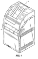
- FIG. 1 shows an exemplary laser imaging machine configured for use with a resealable cartridge, and suitable for incorporation of an opening and closing system in accordance with the present invention.
- FIG. 2 shows an isometric view of a prior art resealable cartridge with the cover removed.
- FIG. 3 shows a top view of the prior art cartridge of FIG. 2 with a portion of the cover removed.
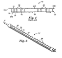
- FIG. 4 shows a side view of the cartridge shown in FIG. 2.
- FIG. 5 shows an isometric view of the opening and closing system of the present invention for opening and closing the cartridge shown in FIG. 2.
- FIG. 6 shows a view of a roller shaft forming part of the opening and closing system of FIG. 5, in accordance with the present invention.
- FIG. 7 shows a side view of the opening and closing system shown in FIG. 5
- FIG. 8 shows a rear partial view of the spring assembly which provides a sealing force.
- FIGS. 9a and 9b show the formation of a wrinkle in the cover which can occur during operation of the opening and closing system of the present invention.
- FIG. 10 shows a bottom isometric view of the opening and closing system shown in FIG. 5 showing the constant force springs used to reduce/eliminate wrinkles.
- FIG. 11 shows an isometric view of the opening and closing system of the present invention disposed within a drawer of a laser imaging machine illustrating a first loading arrangement.
- FIG. 12 shows an isometric view of the opening and closing system of the present invention illustrating a second loading arrangement.
- FIG. 13 shows a partial side view of the opening and closing system of the present invention in a first position referred to as the home position.
- FIG. 14 shows a partial side view of the opening and closing system of the present invention in a second position referred to as the cam lift position.
- FIG. 15 shows a partial side view of the opening and closing system of the present invention in a third position referred to as the cam dwell position.
- FIG. 16 shows a partial side view of the opening and closing system of the present invention in a fourth position referred to as the cover engaged position.
- FIG. 17 shows a partial side view of the opening and closing system of the present invention in a fifth position referred to as the open position.
- FIG. 1 shows an exemplary laser imaging machine 10 configured for use with a resealable cartridge, and suitable for incorporation of an opening and closing system in accordance with the present invention.
- Machine 10 can include a hinged loading door 14 into which a resealable cartridge can be loaded for imaging operations.
- Other suitable laser imaging machines can employ a loading drawer that slides out to receive the cartridge.
- Other loading arrangements may be known to those skilled in the art.
- the cartridge opening/closing system of the present invention is mounted within laser imaging machine 10. After the cartridge has been loaded within laser imaging machine 10, the door/drawer is closed to seal the cartridge within the light-tight environment of laser imaging machine 10. The opening/closing system then operates to open the cartridge to permit access to the photosensitive media in the cartridge. The photosensitive media is withdrawn from the opened cartridge by imaging hardware associated with machine 10. The media is then imaged by other subsystems of laser imaging machine 10. The opening/closing system is also actuated to close the cartridge before the cartridge is removed from laser imaging machine 10. Since the cartridge is resealable, it can be removed from machine 10 before all the photosensitive media within the cartridge has been exposed. Cartridges with different sizes or types of media can therefore be conveniently loaded/reloaded into and removed from laser imaging machine 10 as needed, and without wasting any unused media remaining within the cartridge.
- Laser imaging machine 10 may include more than one drawer so that more than one cartridge can be loaded into machine 10. This may be desirable if the cartridges contain photosensitive media of different sizes. As such, it is noted that the opening/closing system needs to be configured to operate with cartridges containing photosensitive media of different sizes
- Cartridge 12 includes an optically opaque media-receiving tray 20 and a flexible, optically opaque cover 22.
- the flexible cover 22 can be resealably mounted to tray 20 by an adhesive material 24, by means of magnetics, or other method known to those skilled in the art.
- cover 22 is mounted by means of adhesive 24.
- Tray 20 can be molded in one piece from a photo-inert, polyolefin material.
- Tray 20 includes a bottom wall 26, a front wall 28A, a rear wall 28B, opposite side walls 28C, 28D, and a lip having sections 30A-30D extending outward from upper edges of walls 28A-28D, respectively, around a periphery of the tray.
- Adhesive material 24 may take the form of segments of adhesive disposed at intervals along lip sections 30A-30D, or a one-piece adhesive gasket applied to the lip. Side walls 28A-28D and lip sections 30A-30D define an access opening. For laser imaging, the access opening may contain one or more photosensitive media 31, as shown in Figure 2. Photosensitive media 31 may comprise, for example, x-ray film, photosensitive film, photosensitive paper, or other photosensitive substrate materials for imaging applications.
- Tray 20 includes inward projecting guides 32 formed on walls 28A-28D for properly positioning photosensitive media 31.
- Feet 34A-34D are formed into and extend downward from bottom wall 26 to support cartridge 12 within base 18 of the opening and closing mechanism in accordance with the present invention.
- a media presence monitoring well 35 also is formed in bottom wall 26.
- a media presence monitoring sensor associated with laser imaging machine 10 extends into well 35 below the surface of bottom wall 26 when all media have been removed from tray 20, thereby detecting that tray 20 is empty.
- Bottom wall 26 further includes positioning recesses 36, molded into feet 34A and 34B, that extend upward into tray 20 from the exterior surface of the bottom wall.
- Feet 34A, 34B formed adjacent front wall 28A include ramp surfaces 38 that slope downward from the lower edge of the front wall, as shown in Figure 4. Ramp surfaces 38 can be employed to guide feet 34A, 34B over optional locator pins formed in base 18 when cartridge 12 is loaded into the base.
- Tray 20 further includes a recessed area 40 formed in bottom wall 26 that provides a platform on the exterior surface of the bottom wall. The platform formed by recessed area 40 can carry bar code indicia for identifying the type of media contained in cartridge 12.
- a series of evenly spaced cut-out sections 42 are formed in lip section 30A over the top edge of front wall 28A. Cutout sections 42 define a series of spaced projections 44 on lip section 30A.
- a forward area 45 of cover 22 includes a series of elongated apertures 46 aligned with cut-out sections 42 of tray 20 when the cover is disposed over the tray. The cut-out sections 42 cooperate with apertures 46 to facilitate engagement of cover 22 by the opening and closing mechanism of the present invention.
- Cover 22 is preferably a flexible, photo-inert and optically opaque sheet of material sized to extend over the media access opening of tray 20 and mate with lip sections 30A-30D.
- the cover 22 comprises a material that is preferably stretchable enough to avoid pulling away from tray 20 when cartridge 12 is flexed, but rigid enough to resist excessive stretching during opening and closing operations.
- Cover 22 may also include a reinforcing strip (not shown) at a forward area 45 to increase the rigidity of the cover in the area above cut-out sections 42 of tray 20.
- the reinforcing strip is intended to resist tearing of apertures 46 during engagement with the opening and closing mechanism.
- the stretch- resistant material and reinforcing strip of cover 22 are designed to resist the damage caused by certain forces applied to the cover during the opening and closing operations, and thus address the effects of such forces in an effort to extend cartridge life.
- the opening and closing system of the present invention is intended to reduce/eliminate the application of the forces responsible for stretching cover 22 and tearing apertures 46, thereby addressing the source of such problems.
- An exemplary embodiment of the opening and closing mechanism of the present invention will now be described in detail with reference to Figures 5-17.
- an opening and closing system 50 includes a base 52 for receiving and supporting resealable cartridge 12, a roller shaft 54 including means for engaging cover 22, a motor 56 for rotating roller shaft 54, and a carriage 58, slidably coupled to base 52, for supporting roller shaft 54 and motor 56.
- Carriage 58 can be mounted on drawer slides.
- opening and closing system 50 is to open and close cover 22 of cartridge 12.
- Roller shaft 54 rotates and spins along the front edge cartridge 12 until projections/teeth on roller shaft 54 engage apertures 46 in cover 22. Once engaged, roller shaft 54 rolls up onto the front and back walls of cartridge 12 (moving along the length of cartridge 12 in the direction shown by arrow A in Figure 5), thereby wrapping cover 22 around/about the diameter of roller shaft 54. As the motorized roller shaft turns, it moves towards the center of cartridge 12 until cover 22 is open sufficiently to allow a mechanism or other device to remove the media from cartridge 12. Operating roller shaft 54 in the opposite direction reseals cartridge 12.
- roller shaft 54 More particularly, a rotation of roller shaft 54 in the first (opening) direction generates tractional force between roller shaft 54 and cartridge 12.
- a bias means applies a normal force that biases roller shaft 54 downward against cartridge 12.
- the carriage includes means for supporting roller shaft 54 and motor 6, as will be described.
- the tractional force results in a translational force that drives the carriage to slide along tray 20.
- a tractional force generated between roller shaft 54 and cover 22 during the closing operation similarly provides a translational force that drives the carriage to slide.
- Roller shaft 54 is an elongated member, and can be formed of steel.
- a cut-out, winding section 78 extending along a central longitudinal axis, includes means for engaging apertures 46 in cover 22 to open and close cartridge 12.
- winding section 78 has a substantially semi-circular cross-section.
- the cover engaging means of roller shaft 54 comprises an elongated, rectangular plate 80 having a plurality of indentations 82 defining curved, tooth-like projections 84. Projections 84 preferably are sized and spaced to fit within apertures 46 of cover 22, as well as cut-out sections 42, when roller shaft 54 is rotated downward toward base 18.
- Plate 80 and projections 84 may be constructed by stamping them out of a piece of sheet metal, and fastening them with screws 86 to a portion of winding section 78 that has been cut down to approximately a half diameter.
- the radius of curvature of projections 84 can be achieved by bending the plate 80 about a metal form.
- a spring assembly 60 is disposed at each end of roller shaft 54 to provide a sealing force.
- spring assembly 60 includes a pinch roller 62 attached to a bracket 64 that pivots about a shaft 66 attached to a roller link 68.
- a torsion spring 70 provides a torque to apply a suitable sealing force. In one embodiment of the present invention, a torque of 0.66 inch-pounds has been found to apply a suitable sealing force of 1.4 pounds.
- roller shaft 54 Also disposed at each end of roller shaft 54 is a cam 72 which controls the motion of roller shaft 54 and provides indexing of roller shaft 54 during engagement with cover 22.
- a pair of torsion springs 74 disposed at each end of roller shaft 54 direct roller shaft 54 along a cam surface 76 of a pair of cam nests 77, as will be more particularly described below.
- Pivot mechanism 75 links torsion springs 74 with roller shaft 54.
- Motor 56 can be a single dc motor.
- High roller pressure and wrinkles in cover 20 can limit the usable life of cartridge 12. High roller pressure displaces the cover adhesive, resulting in poor sealing characteristics, when the cartridge is open for extended periods (for example, overnight). Wrinkles occur when opening and closing system 50 is closing cartridge 12.
- Figures 9a and 9b illustrate a factor that leads to wrinkles.
- Figure 9a shows roller shaft 54 operating (moving in opening direction D) to open cover 22 wherein a portion 79' of cover 22 does not conform roller shaft 54.
- Figure 9b shows roller shaft 54 during the subsequent closing operation (moving in closing direction E) wherein the non-conforming portion 79'of cover 22 forms on the cartridge as a wrinkle 79".
- a pair of constant force springs 81 supplies a force sufficient to eliminate the wrinkles without pulling cover 22 closed.
- the constant force springs pull carriage 12 toward a frame 83 in the closing direction.
- This addition force eliminates the need for a high sealing force (high forces have been used on previous opening and closing systems), and eliminates the adhesive displacement.
- a force of 0.50 pounds for each constant force spring (1.00 pounds total) has been found to be suitable.
- loading drawer/door 14 is opened and cartridge 12 is loaded into laser imaging machine 10 by sliding cartridge 12 onto base 52 in a direction shown by arrow B.
- One or more slides 85 can be employed to promote the loading/unloading of cartridge 12 in drawer/door 14. Note the positioning of opening and closing 50 relative to the direction of loading of cartridge 12. That is, cartridge 12 is loaded in a direction toward opening and closing system 50. As such, a user is not exposed to projections 84 when loading.
- Figure 11 provides an alternative loading arrangement.
- cartridge 12 is loaded into laser imaging machine 10 by sliding cartridge 12 onto base 52 in a direction shown by arrow C along slide 85.
- cartridge 12 is loaded in a direction along (i.e., parallel to) the axis of roller shaft 54. Opening and closing system 50 is disposed such that it does not interfere with the loading of cartridge 12.
- One or more sensors can be employed to verify the cartridge condition (e.g., presence, absence, and/or proper orientation) of cartridge 12 within laser imaging machine 10.
- These sensors can be mechanical or electrical sensors, as is well known to those skilled in the art.
- three sensors can be employed S1, S2, S3, with the sensors being mechanical members.
- three situations can be determined: the absence of the cartridge, the correct placement of the cartridge, and the incorrect placement of the cartridge.
- the situation can be determined by the state of each sensor. For example, the following can be determined: Other relationships may be known to those skilled in the art.
- one sensor S4 is employed to verify the presence and/or proper orientation of cartridge 12. With the arrangement of Figure 11, the following cartridge conditions can be determined: Cartridge Placement Sensor State None Present Blocked Correct Unblocked
- Opening and closing system 50 can operate using one dc motor (i.e., motor 56) and two position sensors.
- Figures 13-17 illustrate the operation of opening and closing system 50 to open and close cartridge 12.
- Figure 13 shows a partial side view of opening and closing system 50 in a first position, referred to as the home position. This is the position of opening and closing system 50 when cartridge 12 is loaded in laser imaging machine 10. In this position, the components of system 50 are not disposed within the loading area of cartridge 12. In this position, cams 72 actuate a sensor 88 indicating that roller shaft 54 is in the home position. In this position, roller shaft 54 is disposed away from the perforated edge 89 of cover 22, and projections 84 are disposed downward, toward base 52.
- FIG 14 shows a partial side view of opening and closing system 50 in a second position, referred to as the cam lift position.
- each cam 72 interfaces with a surface on cam nest 77 to lift/raise roller shaft 54 towards perforated edge 89 of cover 22.
- Figure 15 shows a partial side view of opening and closing system 50 in a third position, referred to as the cam dwell position.
- each cam 72 interfaces with a surface on cam nest 77 in a dwell state.
- Figure 16 shows a partial side view of opening and closing system 50 in a fourth position, referred to as the cover engaged position.
- roller shaft 54 continues to rotate and projections 84 engage apertures 46 of cover 22.
- Figure 17 shows a partial side view of opening and closing system 50 in a fifth position, referred to as the open position. In this position, an end-of-travel sensor 91 is blocked to indicate the end of the travel for opening and closing system 50.
Landscapes
- Physics & Mathematics (AREA)
- General Physics & Mathematics (AREA)
- Radiography Using Non-Light Waves (AREA)
- Casings For Electric Apparatus (AREA)
- Sheets, Magazines, And Separation Thereof (AREA)
- Closures For Containers (AREA)
Abstract

Description
- The invention relates generally to resealable cartridges, and more particularly, to a system for opening and closing a resealable cartridge.
- Resealable cartridges have been employed in various applications for transporting articles. Such resealable cartridges are desirable features, including preventing exposure of the transported articles to environmental elements. For example, laser imaging machines use resealable cartridges to transport photosensitive media, such as x-ray and other types of medical imaging photographic film, since it is sometimes necessary to load a laser imaging machine with a different type or size of photosensitive media. Such laser imaging machines are well known in the art for forming an image by scanning a modulated laser beam across the photosensitive media. Prior to the formation of the image, a cartridge containing one or more photosensitive media is loaded into the laser imaging machine. The cartridge includes a tray having a supply area for containing the photosensitive media, a media access opening, and a flexible cover adhesively attached to tray to extend over the media access opening to form a light-tight seal of the cartridge. The light-tight seal enables the cartridge to be transported in light conditions that would otherwise cause exposure of the photosensitive media within the cartridge. US Patent No. 5,132,724 (Lemberger), US Patent No. 5,473,400 (Lemberger), and US Patent No. 5,480,134 (Weber) show examples of a resealable cartridge, each of these being incorporated herein by reference.
- The interior of a laser imaging machine provides a light-tight environment. To carry out an imaging operation, the laser imaging machine withdraws one or more photosensitive media from the access opening of the cartridge. Therefore, the laser imaging machine requires a system that can open the cartridge within the laser imaging machine to allow withdrawal of the photosensitive media from the access opening, and close/reseal the cartridge within the laser imaging machine to effect the light-light seal. In the ordinary course of use, the cartridge must be opened and closed several times.
- US Patent No. 5,132,724 (Lemberger) and US Patent No. 5,480,134 (Weber) show examples of mechanisms for opening and closing a resealable media cartridge. While such systems may have achieved certain degrees of success in their particular applications, they employ a relatively complicated mechanism that can be expensive to manufacture and have other disadvantages.
- Accordingly, there is a need for a system which is capable of reliably performing the opening/closing functions, commercially viable, reduced in size, provides good resealing, and efficiently manufacturable.
- The present invention provides a system for opening and closing a resealable cartridge which is capable of reliably performing the opening/closing functions, commercially viable, reduced in size, provides good resealing, and efficiently manufacturable.
- In addition, wrinkles in the cartridge cover can occur while closing, and such wrinkles can decrease the usable life of the cartridge. In addition to wrinkles, laser imaging machines which use high sealing forces tend to displace the cover adhesive. The present invention increases the usable life of the cartridge by reducing/eliminating both wrinkles and displaced cover adhesive.
- Additional features and advantages of the present invention will be set forth in part in the description that follows, and in part will be apparent from the description, or may be learned by practice of the invention. The advantages of the invention will be realized and attained by the system particularly pointed out in the written description and claims thereof, as well as in the appended drawings.
- An object of the present invention is to provide a system for opening and closing a resealable cartridge.
- Another object of the present invention is to provide such a system which is capable of reliably performing the opening/closing functions.
- A further object of the present invention is to provide such a system which is commercially viable, reduced in size, provides good resealing, and efficiently manufacturable.
- These objects are given only by way of illustrative example, and such objects may be exemplary of one or more embodiments of the invention. Other desirable objectives and advantages inherently achieved by the disclosed invention may occur or become apparent to those skilled in the art. The invention is defined by the appended claims.
- According to one aspect of the invention, there is provided a system for opening and closing a resealable cartridge having a tray and a flexible cover resealably engaged with the tray. The system comprises: a base for receiving the tray of the cartridge; a roller shaft having means for engaging the cover of the cartridge; positioning means operably connected to the roller shaft to affect positioning of the roller shaft relative to the cartridge between a first position wherein the roller shaft is spaced from the cartridge and a second position different from the first position wherein the roller shaft is not spaced from the cartridge; and a motor for rotating the roller shaft in a first rotational direction to wind the cover about the roller shaft, thereby removing at least a portion of the cover from the tray, and for rotating the roller shaft in a second rotational direction to unwind the cover from the roller shaft thereby resealably engaging the cover with the tray.
- The foregoing and other objects, features, and advantages of the invention will be apparent from the following more particular description of the preferred embodiments of the invention, as illustrated in the accompanying drawings.
- FIG. 1 shows an exemplary laser imaging machine configured for use with a resealable cartridge, and suitable for incorporation of an opening and closing system in accordance with the present invention.
- FIG. 2 shows an isometric view of a prior art resealable cartridge with the cover removed.
- FIG. 3 shows a top view of the prior art cartridge of FIG. 2 with a portion of the cover removed.
- FIG. 4 shows a side view of the cartridge shown in FIG. 2.
- FIG. 5 shows an isometric view of the opening and closing system of the present invention for opening and closing the cartridge shown in FIG. 2.
- FIG. 6 shows a view of a roller shaft forming part of the opening and closing system of FIG. 5, in accordance with the present invention.
- FIG. 7 shows a side view of the opening and closing system shown in FIG. 5
- FIG. 8 shows a rear partial view of the spring assembly which provides a sealing force.
- FIGS. 9a and 9b show the formation of a wrinkle in the cover which can occur during operation of the opening and closing system of the present invention.
- FIG. 10 shows a bottom isometric view of the opening and closing system shown in FIG. 5 showing the constant force springs used to reduce/eliminate wrinkles.
- FIG. 11 shows an isometric view of the opening and closing system of the present invention disposed within a drawer of a laser imaging machine illustrating a first loading arrangement.
- FIG. 12 shows an isometric view of the opening and closing system of the present invention illustrating a second loading arrangement.
- FIG. 13 shows a partial side view of the opening and closing system of the present invention in a first position referred to as the home position.
- FIG. 14 shows a partial side view of the opening and closing system of the present invention in a second position referred to as the cam lift position.
- FIG. 15 shows a partial side view of the opening and closing system of the present invention in a third position referred to as the cam dwell position.
- FIG. 16 shows a partial side view of the opening and closing system of the present invention in a fourth position referred to as the cover engaged position.
- FIG. 17 shows a partial side view of the opening and closing system of the present invention in a fifth position referred to as the open position.
- The following is a detailed description of the preferred embodiments of the invention, reference being made to the drawings in which the same reference numerals identify the same elements of structure in each of the several figures.
- Figure 1 shows an exemplary
laser imaging machine 10 configured for use with a resealable cartridge, and suitable for incorporation of an opening and closing system in accordance with the present invention.Machine 10 can include a hingedloading door 14 into which a resealable cartridge can be loaded for imaging operations. Other suitable laser imaging machines can employ a loading drawer that slides out to receive the cartridge. Other loading arrangements may be known to those skilled in the art. - The cartridge opening/closing system of the present invention is mounted within
laser imaging machine 10. After the cartridge has been loaded withinlaser imaging machine 10, the door/drawer is closed to seal the cartridge within the light-tight environment oflaser imaging machine 10. The opening/closing system then operates to open the cartridge to permit access to the photosensitive media in the cartridge. The photosensitive media is withdrawn from the opened cartridge by imaging hardware associated withmachine 10. The media is then imaged by other subsystems oflaser imaging machine 10. The opening/closing system is also actuated to close the cartridge before the cartridge is removed fromlaser imaging machine 10. Since the cartridge is resealable, it can be removed frommachine 10 before all the photosensitive media within the cartridge has been exposed. Cartridges with different sizes or types of media can therefore be conveniently loaded/reloaded into and removed fromlaser imaging machine 10 as needed, and without wasting any unused media remaining within the cartridge. -
Laser imaging machine 10 may include more than one drawer so that more than one cartridge can be loaded intomachine 10. This may be desirable if the cartridges contain photosensitive media of different sizes. As such, it is noted that the opening/closing system needs to be configured to operate with cartridges containing photosensitive media of different sizes - An exemplary
resealable cartridge 12 is described with reference to Figures 2 through 4. Other configurations may be known to those skilled in the art. Since resealable cartridges are well-known, the cartridge will not be discussed in detail. -
Cartridge 12 includes an optically opaque media-receivingtray 20 and a flexible, opticallyopaque cover 22. Theflexible cover 22 can be resealably mounted totray 20 by anadhesive material 24, by means of magnetics, or other method known to those skilled in the art. For ease of explanation of the present invention, cover 22 is mounted by means of adhesive 24.Tray 20 can be molded in one piece from a photo-inert, polyolefin material.Tray 20 includes abottom wall 26, afront wall 28A, arear wall 28B,opposite side walls lip having sections 30A-30D extending outward from upper edges ofwalls 28A-28D, respectively, around a periphery of the tray.Adhesive material 24 may take the form of segments of adhesive disposed at intervals alonglip sections 30A-30D, or a one-piece adhesive gasket applied to the lip.Side walls 28A-28D andlip sections 30A-30D define an access opening. For laser imaging, the access opening may contain one or morephotosensitive media 31, as shown in Figure 2.Photosensitive media 31 may comprise, for example, x-ray film, photosensitive film, photosensitive paper, or other photosensitive substrate materials for imaging applications. -
Tray 20 includes inward projectingguides 32 formed onwalls 28A-28D for properly positioningphotosensitive media 31.Feet 34A-34D are formed into and extend downward frombottom wall 26 to supportcartridge 12 within base 18 of the opening and closing mechanism in accordance with the present invention. A media presence monitoring well 35 also is formed inbottom wall 26. A media presence monitoring sensor associated withlaser imaging machine 10 extends into well 35 below the surface ofbottom wall 26 when all media have been removed fromtray 20, thereby detecting thattray 20 is empty.Bottom wall 26 further includes positioning recesses 36, molded intofeet tray 20 from the exterior surface of the bottom wall. -
Feet front wall 28A include ramp surfaces 38 that slope downward from the lower edge of the front wall, as shown in Figure 4. Ramp surfaces 38 can be employed to guidefeet cartridge 12 is loaded into the base.Tray 20 further includes a recessedarea 40 formed inbottom wall 26 that provides a platform on the exterior surface of the bottom wall. The platform formed by recessedarea 40 can carry bar code indicia for identifying the type of media contained incartridge 12. - With reference to Figures 2 and 3, a series of evenly spaced cut-out
sections 42 are formed inlip section 30A over the top edge offront wall 28A.Cutout sections 42 define a series of spacedprojections 44 onlip section 30A. Aforward area 45 ofcover 22 includes a series ofelongated apertures 46 aligned with cut-outsections 42 oftray 20 when the cover is disposed over the tray. The cut-outsections 42 cooperate withapertures 46 to facilitate engagement ofcover 22 by the opening and closing mechanism of the present invention. -
Cover 22 is preferably a flexible, photo-inert and optically opaque sheet of material sized to extend over the media access opening oftray 20 and mate withlip sections 30A-30D. Thecover 22 comprises a material that is preferably stretchable enough to avoid pulling away fromtray 20 whencartridge 12 is flexed, but rigid enough to resist excessive stretching during opening and closing operations.Cover 22 may also include a reinforcing strip (not shown) at aforward area 45 to increase the rigidity of the cover in the area above cut-outsections 42 oftray 20. The reinforcing strip is intended to resist tearing ofapertures 46 during engagement with the opening and closing mechanism. The stretch- resistant material and reinforcing strip ofcover 22 are designed to resist the damage caused by certain forces applied to the cover during the opening and closing operations, and thus address the effects of such forces in an effort to extend cartridge life. - The opening and closing system of the present invention is intended to reduce/eliminate the application of the forces responsible for stretching
cover 22 and tearingapertures 46, thereby addressing the source of such problems. An exemplary embodiment of the opening and closing mechanism of the present invention will now be described in detail with reference to Figures 5-17. - Referring first to Figures 5-8, an opening and
closing system 50 includes abase 52 for receiving and supportingresealable cartridge 12, aroller shaft 54 including means for engagingcover 22, amotor 56 for rotatingroller shaft 54, and acarriage 58, slidably coupled tobase 52, for supportingroller shaft 54 andmotor 56.Carriage 58 can be mounted on drawer slides. - Generally, the purpose of opening and
closing system 50 is to open andclose cover 22 ofcartridge 12.Roller shaft 54 rotates and spins along thefront edge cartridge 12 until projections/teeth onroller shaft 54 engageapertures 46 incover 22. Once engaged,roller shaft 54 rolls up onto the front and back walls of cartridge 12 (moving along the length ofcartridge 12 in the direction shown by arrow A in Figure 5), thereby wrappingcover 22 around/about the diameter ofroller shaft 54. As the motorized roller shaft turns, it moves towards the center ofcartridge 12 untilcover 22 is open sufficiently to allow a mechanism or other device to remove the media fromcartridge 12. Operatingroller shaft 54 in the opposite direction resealscartridge 12. - More particularly, a rotation of
roller shaft 54 in the first (opening) direction generates tractional force betweenroller shaft 54 andcartridge 12. A bias means applies a normal force thatbiases roller shaft 54 downward againstcartridge 12. The carriage includes means for supportingroller shaft 54 and motor 6, as will be described. - The tractional force results in a translational force that drives the carriage to slide along
tray 20. A tractional force generated betweenroller shaft 54 and cover 22 during the closing operation similarly provides a translational force that drives the carriage to slide. -
Roller shaft 54 is an elongated member, and can be formed of steel. A cut-out, windingsection 78, extending along a central longitudinal axis, includes means for engagingapertures 46 incover 22 to open andclose cartridge 12. As shown in Figure 6, windingsection 78 has a substantially semi-circular cross-section. In the embodiment shown, the cover engaging means ofroller shaft 54 comprises an elongated,rectangular plate 80 having a plurality ofindentations 82 defining curved, tooth-like projections 84.Projections 84 preferably are sized and spaced to fit withinapertures 46 ofcover 22, as well as cut-outsections 42, whenroller shaft 54 is rotated downward toward base 18.Plate 80 andprojections 84 may be constructed by stamping them out of a piece of sheet metal, and fastening them withscrews 86 to a portion of windingsection 78 that has been cut down to approximately a half diameter. The radius of curvature ofprojections 84 can be achieved by bending theplate 80 about a metal form. - A
spring assembly 60 is disposed at each end ofroller shaft 54 to provide a sealing force. As best shown in Figure 8,spring assembly 60 includes apinch roller 62 attached to abracket 64 that pivots about ashaft 66 attached to aroller link 68. Atorsion spring 70 provides a torque to apply a suitable sealing force. In one embodiment of the present invention, a torque of 0.66 inch-pounds has been found to apply a suitable sealing force of 1.4 pounds. - Also disposed at each end of
roller shaft 54 is acam 72 which controls the motion ofroller shaft 54 and provides indexing ofroller shaft 54 during engagement withcover 22. A pair of torsion springs 74 disposed at each end ofroller shaft 54direct roller shaft 54 along a cam surface 76 of a pair ofcam nests 77, as will be more particularly described below. -
Pivot mechanism 75 links torsion springs 74 withroller shaft 54.Motor 56 can be a single dc motor. - High roller pressure and wrinkles in
cover 20 can limit the usable life ofcartridge 12. High roller pressure displaces the cover adhesive, resulting in poor sealing characteristics, when the cartridge is open for extended periods (for example, overnight). Wrinkles occur when opening andclosing system 50 is closingcartridge 12. Figures 9a and 9b illustrate a factor that leads to wrinkles. Figure 9a showsroller shaft 54 operating (moving in opening direction D) to opencover 22 wherein a portion 79' ofcover 22 does not conformroller shaft 54. Figure 9b showsroller shaft 54 during the subsequent closing operation (moving in closing direction E) wherein the non-conforming portion 79'of cover 22 forms on the cartridge as awrinkle 79". - It was determined that adding a force in the closing direction (i.e., during the closing operation) keeps
cover 22 tight/taught againstroller shaft 54, thereby eliminating non-conforming cover portions and hence the wrinkles. Referring to Figure 10, a pair of constant force springs 81 supplies a force sufficient to eliminate the wrinkles without pullingcover 22 closed. The constant force springs pullcarriage 12 toward aframe 83 in the closing direction. This addition force eliminates the need for a high sealing force (high forces have been used on previous opening and closing systems), and eliminates the adhesive displacement. A force of 0.50 pounds for each constant force spring (1.00 pounds total) has been found to be suitable. - Referring now to Figure 11, in operation, loading drawer/
door 14 is opened andcartridge 12 is loaded intolaser imaging machine 10 by slidingcartridge 12 ontobase 52 in a direction shown by arrow B. One ormore slides 85 can be employed to promote the loading/unloading ofcartridge 12 in drawer/door 14. Note the positioning of opening and closing 50 relative to the direction of loading ofcartridge 12. That is,cartridge 12 is loaded in a direction toward opening andclosing system 50. As such, a user is not exposed toprojections 84 when loading. - Figure 11 provides an alternative loading arrangement. In this arrangement,
cartridge 12 is loaded intolaser imaging machine 10 by slidingcartridge 12 ontobase 52 in a direction shown by arrow C alongslide 85. With this loading arrangement,cartridge 12 is loaded in a direction along (i.e., parallel to) the axis ofroller shaft 54. Opening and closingsystem 50 is disposed such that it does not interfere with the loading ofcartridge 12. - One or more sensors can be employed to verify the cartridge condition (e.g., presence, absence, and/or proper orientation) of
cartridge 12 withinlaser imaging machine 10. These sensors can be mechanical or electrical sensors, as is well known to those skilled in the art. For example, referring to Figure 12, three sensors can be employed S1, S2, S3, with the sensors being mechanical members. With three sensors, three situations can be determined: the absence of the cartridge, the correct placement of the cartridge, and the incorrect placement of the cartridge. The situation can be determined by the state of each sensor. For example, the following can be determined:Other relationships may be known to those skilled in the art.
- Referring again to Figure 11, one sensor S4 is employed to verify the presence and/or proper orientation of
cartridge 12. With the arrangement of Figure 11, the following cartridge conditions can be determined:Cartridge Placement Sensor State None Present Blocked Correct Unblocked - Opening and closing
system 50 can operate using one dc motor (i.e., motor 56) and two position sensors. Figures 13-17 illustrate the operation of opening andclosing system 50 to open andclose cartridge 12. - Figure 13 shows a partial side view of opening and
closing system 50 in a first position, referred to as the home position. This is the position of opening andclosing system 50 whencartridge 12 is loaded inlaser imaging machine 10. In this position, the components ofsystem 50 are not disposed within the loading area ofcartridge 12. In this position,cams 72 actuate asensor 88 indicating thatroller shaft 54 is in the home position. In this position,roller shaft 54 is disposed away from theperforated edge 89 ofcover 22, andprojections 84 are disposed downward, towardbase 52. - Figure 14 shows a partial side view of opening and
closing system 50 in a second position, referred to as the cam lift position. In this position, eachcam 72 interfaces with a surface oncam nest 77 to lift/raise roller shaft 54 towardsperforated edge 89 ofcover 22. - Figure 15 shows a partial side view of opening and
closing system 50 in a third position, referred to as the cam dwell position. In this position, eachcam 72 interfaces with a surface oncam nest 77 in a dwell state. - Figure 16 shows a partial side view of opening and
closing system 50 in a fourth position, referred to as the cover engaged position. In this position,roller shaft 54 continues to rotate andprojections 84 engageapertures 46 ofcover 22. - Figure 17 shows a partial side view of opening and
closing system 50 in a fifth position, referred to as the open position. In this position, an end-of-travel sensor 91 is blocked to indicate the end of the travel for opening andclosing system 50. - Reversing the positions shown in Figures 13-17 effects closure/sealing of
cover 22 oncartridge 12.
Claims (9)
- A system for opening and closing a resealable cartridge having a tray and a flexible cover resealably engaged with the tray, the system comprising:a base for receiving the tray of the cartridge;a roller shaft having means for engaging the cover of the cartridge;positioning means operably connected to the roller shaft to affect positioning of the roller shaft relative to the cartridge between a first position wherein the roller shaft is spaced from the cartridge and a second position different from the first position wherein the roller shaft is not spaced from the cartridge; anda motor for rotating the roller shaft in a first rotational direction to wind the cover about the roller shaft, thereby removing at least a portion of the cover from the tray, and for rotating the roller shaft in a second rotational direction to unwind the cover from the roller shaft thereby resealably engaging the cover with the tray.
- The system of Claim 1, wherein the positioning means includes a cam.
- The system of Claim 1, wherein the positioning means includes a cam and a cam nest.
- The system of Claim 3, wherein the system further includes at least one torsion spring biasing the cam toward the cam nest.
- The system of Clam 1, further comprising at least one constant force spring biasing the roller shaft toward the cartridge when the roller shaft is rotating in the second rotational direction.
- The system of Claim 1, further comprising:first sensing means positioned at a first location for sensing a first position of the roller shaft wherein the roller shaft is spaced from the cartridge; andsecond sensing means positioned at a second location different than the first location for sensing a second position of the roller shaft indicative of the removal of at least a portion of the cover from the tray.
- The system of Claim 6, wherein the first and second sensing means are activated by the opening and closing system.
- A system for opening and closing a resealable cartridge having a tray and a flexible cover resealably engaged with the tray, the system comprising:a base for receiving the tray of the cartridge;a roller shaft having means for engaging the cover of the cartridge;a motor for rotating the roller shaft in a first rotational direction to wind the cover about the roller shaft, thereby removing at least a portion of the cover from the tray, and for rotating the roller shaft in a second rotational direction to unwind the cover from the roller shaft thereby resealably engaging the cover with the tray; andpositioning means operably connected to the roller shaft to affect positioning of the roller shaft, the positioning means positioning the roller shaft in a first position spaced from the cartridge and disposed intermediate the base and the cover.
- The system of Claim 8, wherein the positioning means includes a cam operably connected to the roller shaft.
Applications Claiming Priority (2)
| Application Number | Priority Date | Filing Date | Title |
|---|---|---|---|
| US10/376,540 US6832862B2 (en) | 2003-02-28 | 2003-02-28 | System for opening and closing a resealable cartridge |
| US376540 | 2003-02-28 |
Publications (2)
| Publication Number | Publication Date |
|---|---|
| EP1452909A1 true EP1452909A1 (en) | 2004-09-01 |
| EP1452909B1 EP1452909B1 (en) | 2006-10-11 |
Family
ID=32771497
Family Applications (1)
| Application Number | Title | Priority Date | Filing Date |
|---|---|---|---|
| EP04075512A Expired - Lifetime EP1452909B1 (en) | 2003-02-28 | 2004-02-16 | System for opening and closing a resealable cartridge |
Country Status (5)
| Country | Link |
|---|---|
| US (2) | US6832862B2 (en) |
| EP (1) | EP1452909B1 (en) |
| JP (1) | JP4303615B2 (en) |
| CN (1) | CN1530740A (en) |
| DE (1) | DE602004002707T2 (en) |
Families Citing this family (7)
| Publication number | Priority date | Publication date | Assignee | Title |
|---|---|---|---|---|
| US6832862B2 (en) * | 2003-02-28 | 2004-12-21 | Eastman Kodak Company | System for opening and closing a resealable cartridge |
| US7735982B2 (en) * | 2004-01-21 | 2010-06-15 | Silverbrook Research Pty Ltd | Digital photofinishing system cartridge |
| US7140608B2 (en) * | 2004-10-28 | 2006-11-28 | International Currency Technology Corporation | Bill box for bill acceptor |
| JP2009503619A (en) * | 2005-08-01 | 2009-01-29 | サウスコ,インコーポレイティド | Sliding and rotating hinge module |
| DE112008000441T5 (en) * | 2007-02-21 | 2010-03-04 | Southco, Inc. | Hinge module with sliding and rotating movement |
| ES2467932T3 (en) * | 2011-09-21 | 2014-06-13 | Agfa Healthcare N.V. | Device, system and method for reading x-ray information stored on luminescent storage plates |
| EP3773778B1 (en) | 2018-04-02 | 2025-11-12 | IC Surgical, Inc. | Negative pressure pumps and related methods |
Citations (5)
| Publication number | Priority date | Publication date | Assignee | Title |
|---|---|---|---|---|
| EP0624535A1 (en) * | 1993-04-30 | 1994-11-17 | Hewlett-Packard Company | Sheet media realignment mechanism |
| US5404194A (en) * | 1991-07-22 | 1995-04-04 | Minolta Co., Ltd. | Cover winding apparatus for winding cover attached to opening part of container |
| US5480134A (en) * | 1994-05-09 | 1996-01-02 | Minnesota Mining And Manufacturing Company | Mechanism for opening and closing a resealable cartridge |
| US6139005A (en) * | 1997-09-29 | 2000-10-31 | Eastman Kodak Company | Film supply system for use with a photosensitive film imager |
| EP1199268A1 (en) * | 1996-09-18 | 2002-04-24 | Hewlett-Packard Company | Automatic sheet feeding mechanism |
Family Cites Families (4)
| Publication number | Priority date | Publication date | Assignee | Title |
|---|---|---|---|---|
| JP2763358B2 (en) * | 1989-12-28 | 1998-06-11 | ミノルタ株式会社 | Cover winding device |
| EP0572568B1 (en) * | 1991-02-19 | 1995-01-11 | Minnesota Mining And Manufacturing Company | Resealable film cartridge for a laser imager |
| US5132724A (en) * | 1991-02-19 | 1992-07-21 | Minnesota Mining And Manufacturing Company | Opening and closing mechanism for a laser imager film cartridge |
| US6832862B2 (en) * | 2003-02-28 | 2004-12-21 | Eastman Kodak Company | System for opening and closing a resealable cartridge |
-
2003
- 2003-02-28 US US10/376,540 patent/US6832862B2/en not_active Expired - Fee Related
-
2004
- 2004-02-16 EP EP04075512A patent/EP1452909B1/en not_active Expired - Lifetime
- 2004-02-16 DE DE602004002707T patent/DE602004002707T2/en not_active Expired - Fee Related
- 2004-02-27 JP JP2004054252A patent/JP4303615B2/en not_active Expired - Fee Related
- 2004-02-27 CN CNA2004100076492A patent/CN1530740A/en active Pending
- 2004-08-02 US US10/909,702 patent/US7232266B2/en not_active Expired - Fee Related
Patent Citations (5)
| Publication number | Priority date | Publication date | Assignee | Title |
|---|---|---|---|---|
| US5404194A (en) * | 1991-07-22 | 1995-04-04 | Minolta Co., Ltd. | Cover winding apparatus for winding cover attached to opening part of container |
| EP0624535A1 (en) * | 1993-04-30 | 1994-11-17 | Hewlett-Packard Company | Sheet media realignment mechanism |
| US5480134A (en) * | 1994-05-09 | 1996-01-02 | Minnesota Mining And Manufacturing Company | Mechanism for opening and closing a resealable cartridge |
| EP1199268A1 (en) * | 1996-09-18 | 2002-04-24 | Hewlett-Packard Company | Automatic sheet feeding mechanism |
| US6139005A (en) * | 1997-09-29 | 2000-10-31 | Eastman Kodak Company | Film supply system for use with a photosensitive film imager |
Also Published As
| Publication number | Publication date |
|---|---|
| JP2004266277A (en) | 2004-09-24 |
| US6832862B2 (en) | 2004-12-21 |
| DE602004002707D1 (en) | 2006-11-23 |
| US20050035533A1 (en) | 2005-02-17 |
| CN1530740A (en) | 2004-09-22 |
| US7232266B2 (en) | 2007-06-19 |
| DE602004002707T2 (en) | 2007-08-16 |
| EP1452909B1 (en) | 2006-10-11 |
| JP4303615B2 (en) | 2009-07-29 |
| US20040170424A1 (en) | 2004-09-02 |
Similar Documents
| Publication | Publication Date | Title |
|---|---|---|
| US5229585A (en) | Film cartridge bar code scanner and controller for a digital imaging system | |
| EP0572885B1 (en) | Apparatus for separating film from X-ray cassettes | |
| EP1452909B1 (en) | System for opening and closing a resealable cartridge | |
| AU653225B2 (en) | Resealable film cartridge for a laser imager | |
| EP0500280B1 (en) | Opening and closing mechanism for a laser imager film cartridge | |
| CN1213346C (en) | Photosensitive tape cartridge of electrophotographic imaging device and hpotosensitive tape mounting device and its using method | |
| EP0759186B1 (en) | Mechanism for opening and closing a resealable cartridge | |
| US6778262B2 (en) | Film conveying apparatus | |
| US6312169B1 (en) | Relockable film cartridge for a photographic system | |
| US5909853A (en) | Film-rewinding apparatus | |
| JPH0212859B2 (en) | ||
| EP0987592B1 (en) | Relockable film cartridge for a photographic system | |
| EP1146387B1 (en) | Relockable film cartridge for photographic film | |
| US6398427B1 (en) | Relockable film cartridge for photographic film | |
| JP2529551B2 (en) | Film loading device | |
| US5926654A (en) | Camera frame assembly having a baffled supply chamber and film loading apparatus and method | |
| JP3253337B2 (en) | Paper feeder of image forming device that can be inserted with each paper pack | |
| EP1046950A2 (en) | Relockable film cassette for photographic imaging station | |
| JPH05193748A (en) | Paper sheet feeding device of image forming device capable of positioning paper sheet pack and correcting direction thereof | |
| JPH05186067A (en) | Paper sheet feeder for image forming device by which use of paper sheet pack can be prohibited |
Legal Events
| Date | Code | Title | Description |
|---|---|---|---|
| PUAI | Public reference made under article 153(3) epc to a published international application that has entered the european phase |
Free format text: ORIGINAL CODE: 0009012 |
|
| AK | Designated contracting states |
Kind code of ref document: A1 Designated state(s): AT BE BG CH CY CZ DE DK EE ES FI FR GB GR HU IE IT LI LU MC NL PT RO SE SI SK TR |
|
| AX | Request for extension of the european patent |
Extension state: AL LT LV MK |
|
| 17P | Request for examination filed |
Effective date: 20050119 |
|
| 17Q | First examination report despatched |
Effective date: 20050221 |
|
| AKX | Designation fees paid |
Designated state(s): DE FR GB |
|
| RBV | Designated contracting states (corrected) |
Designated state(s): DE FR GB |
|
| GRAP | Despatch of communication of intention to grant a patent |
Free format text: ORIGINAL CODE: EPIDOSNIGR1 |
|
| GRAS | Grant fee paid |
Free format text: ORIGINAL CODE: EPIDOSNIGR3 |
|
| GRAA | (expected) grant |
Free format text: ORIGINAL CODE: 0009210 |
|
| AK | Designated contracting states |
Kind code of ref document: B1 Designated state(s): DE FR GB |
|
| REG | Reference to a national code |
Ref country code: GB Ref legal event code: FG4D |
|
| REF | Corresponds to: |
Ref document number: 602004002707 Country of ref document: DE Date of ref document: 20061123 Kind code of ref document: P |
|
| ET | Fr: translation filed | ||
| PLBE | No opposition filed within time limit |
Free format text: ORIGINAL CODE: 0009261 |
|
| STAA | Information on the status of an ep patent application or granted ep patent |
Free format text: STATUS: NO OPPOSITION FILED WITHIN TIME LIMIT |
|
| 26N | No opposition filed |
Effective date: 20070712 |
|
| REG | Reference to a national code |
Ref country code: GB Ref legal event code: 732E |
|
| PGFP | Annual fee paid to national office [announced via postgrant information from national office to epo] |
Ref country code: FR Payment date: 20080212 Year of fee payment: 5 |
|
| GBPC | Gb: european patent ceased through non-payment of renewal fee |
Effective date: 20080216 |
|
| REG | Reference to a national code |
Ref country code: FR Ref legal event code: TP |
|
| REG | Reference to a national code |
Ref country code: FR Ref legal event code: TP |
|
| PGFP | Annual fee paid to national office [announced via postgrant information from national office to epo] |
Ref country code: DE Payment date: 20090227 Year of fee payment: 6 |
|
| PG25 | Lapsed in a contracting state [announced via postgrant information from national office to epo] |
Ref country code: GB Free format text: LAPSE BECAUSE OF NON-PAYMENT OF DUE FEES Effective date: 20080216 |
|
| REG | Reference to a national code |
Ref country code: FR Ref legal event code: ST Effective date: 20091030 |
|
| PG25 | Lapsed in a contracting state [announced via postgrant information from national office to epo] |
Ref country code: FR Free format text: LAPSE BECAUSE OF NON-PAYMENT OF DUE FEES Effective date: 20090302 |
|
| PG25 | Lapsed in a contracting state [announced via postgrant information from national office to epo] |
Ref country code: DE Free format text: LAPSE BECAUSE OF NON-PAYMENT OF DUE FEES Effective date: 20100901 |