Technical Field
The present invention relates to a biosensor for
carrying out prompt and highly accurate quantification of a
measuring subject in a sample with ease.
Background Art
Conventionally, the following biosensor has been
proposed as a system for simplified quantification of a
specific component in a sample without diluting or stirring
the sample solution (Japanese Laid-Open Patent Publication Hei
No. 2-062952).
This biosensor is produced by forming an electrode
system comprising a measuring electrode, a counter electrode
and a reference electrode on an electrically insulating base
plate by a method such as screen printing and forming a
reaction reagent layer comprising a hydrophilic polymer, an
oxidoreductase and an electron mediator on the electrode
system. A buffer is added to the reaction reagent layer, when
necessary.
In order to introduce a sample solution to the
vicinity of the electrode system and dissolve the reaction
reagent layer to initiate an enzyme reaction, the biosensor
includes a cover member which is joined to the base plate to
form a sample solution supply pathway for supplying the sample
solution to the electrode system between the cover member and
the base plate, and the cover member has an air vent for
facilitating the introduction of the sample solution. This
structure allows the sample solution to be introduced into the
sample solution supply pathway by capillarity to reach the
vicinity of the electrode system.
When a sample solution containing a substrate is
introduced into a biosensor having such a structure,
dissolution of the reaction reagent layer takes place, causing
a reaction between the enzyme and the substrate, and this
enzyme reaction is accompanied by reduction of the electron
mediator. Upon completion of the enzyme reaction, the reduced
electron mediator is electrochemically oxidized, and based on
the oxidation current value upon the oxidation, the
concentration of the substrate in the sample solution can be
determined.
This biosensor is theoretically applicable to
measurements of various substances by using an enzyme whose
substrate is the substance to be measured.
For example, the use of glucose oxidase as the
oxidoreductase can yield a biosensor for measuring glucose
concentration in blood. Glucose sensors based on the above-described
principle have found extensive commercial
application.
Also, the use of cholesterol oxidase can yield a
biosensor for measuring serum cholesterol. However, serum
cholesterol level serving as diagnostic standard is the sum of
cholesterol and cholesterol ester concentrations.
Since cholesterol ester cannot serve as a substrate
of the oxidation reaction by cholesterol oxidase, a process of
converting cholesterol ester into cholesterol is necessary for
measuring serum cholesterol level as diagnostic standard.
Cholesterol esterase is known as an enzyme for catalyzing this
process.
Therefore, it is theoretically possible to measure
the total cholesterol concentration in serum by a biosensor
having a reaction reagent system containing cholesterol
esterase and cholesterol oxidase.
However, in such a biosensor having the above-described
constitution, when the sample solution is a low-viscosity
solution which does not contain protein or the like,
the sample solution permeates the sample solution supply
pathway so quickly that it may not only fill the sample
solution supply pathway but also overflow into the air vent.
In this case, the concentration of the dissolved reaction
reagent layer somewhat decreases. The concentration of the
reduced electron mediator produced by the enzyme reaction
depends on the concentration of the substrate in the sample
solution regardless of the concentration of the reaction
reagents, and it is therefore thought that there is no
influence on the response value if a sufficient reaction time
is given. However, the decrease in the concentration of the
reaction reagent layer may slow the enzyme reaction, possibly
resulting in a decrease in the response value.
Also, the reaction reagent layer is generally formed
by dropping a mixed aqueous solution containing a hydrophilic
polymer, an oxidoreductase and an electron mediator onto the
electrode system and drying it. If such a reaction reagent
layer contains excessively large amounts of reagents, the
reaction reagent layer does not dissolve promptly upon
dropping of the sample solution, thereby causing a problem of
requiring long time for making a measurement.
Particularly, when the above-described constitution
of the biosensor is applied to a cholesterol sensor, the
dissolution of the reaction reagent layer requires
considerably long time in a measurement, because the use of
two kinds of enzymes, cholesterol oxidase and cholesterol
esterase, is necessary.
When the reaction reagent layer is formed, partly or
wholly, by freeze drying an aqueous solution of reagents, the
solubility of the reaction reagent layer can be improved, so
that shortening the measuring time is possible (U.S. Pat. No.
6,451,372, for example).
However, in the case of forming, by freeze drying,
the reaction reagent layer in the cavity constituting the
sample solution supply pathway of the cover member, if the air
vent adjacent to the cavity has a round shape, the sample
solution supply pathway has such a shape that the side walls
thereof protrude toward the air vent relative to the center
thereof. Thus, when the reaction reagent solution is dropped
in the cavity of the cover member, the surface shape of the
contacting part of the reaction reagent solution with the air
vent becomes distorted. In the case of drying by freeze
drying, the surface shape of the dried reaction reagent layer
also becomes distorted, since the solution is dried while the
outer shape in a state of solution is almost retained.
In a biosensor having a reaction layer formed in
such a manner, the homogeneous solubility of the reaction
reagent layer upon the supply of the sample solution is
somewhat impaired. Since the thickness of the reaction
reagent layer tends to increase particularly near the
interface between the reaction reagent layer and the air vent,
only the thickened part may remain undissolved. This tendency
is particularly remarkable when a whole blood sample is
measured by a sensor having a hemocyte-filtering filter in
front of the sample solution supply pathway, because the
permeation of the filtered liquid (plasma) into the sample
solution supply pathway is relatively slow.
In view of the above problems, an object of the
present invention is to provide a biosensor enabling accurate
measurements.
Another object of the present invention is to
provide a biosensor which allows prompt and homogeneous
dissolution of reagents necessary for measurements such as an
enzyme and an electron mediator into a sample solution and
which is therefore capable of prompt and accurate measurements.
Disclosure of Invention
The present invention provides a biosensor
comprising: an electrically insulating base plate; an
electrode system comprising at least a measuring electrode and
a counter electrode formed on the base plate; a cover member
which is joined to the base plate to form a sample solution
supply pathway for supplying a sample solution to the
electrode system between the cover member and the base plate;
and a reaction reagent carried at a position which is exposed
to the sample solution supply pathway, wherein the cover
member comprises a cover which is disposed at a position
opposite to the electrode system formed on the base plate and
a spacer which is inserted between the cover and the base
plate, the spacer having a slit for forming the sample
solution supply pathway, the cover has an air vent
communicating with the slit of the spacer, and a part of the
cover facing the air vent and constituting the ceiling of the
sample solution supply pathway protrudes at its center toward
the air vent relative to the side walls of the sample solution
supply pathway.
It is preferable that the width of the opening of
the air vent in the longitudinal direction of the sample
solution supply pathway be 0.5 mm at the maximum and 0.1 mm at
the minimum.
It is preferable that at least a part of the
reaction reagent be carried on a surface of the cover member
exposed to the sample solution supply pathway.
It is preferable that the reaction reagent comprise
at least cholesterol oxidase and an enzyme capable of
hydrolyzing cholesterol ester.
Brief Description of Drawings
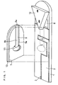
FIG. 1 is an exploded perspective view of a
biosensor in one example of the present invention.
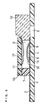
FIG. 2 is a longitudinal sectional view of the
biosensor.
FIG. 3 is a plane view of a cover member of the
biosensor.
FIG. 4 is a plane view of a cover member of a
biosensor in another example of the present invention.
FIG. 5 is a longitudinal sectional view of the cover
member of the biosensor with a reagent layer formed on the
cover member.
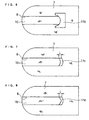
FIG. 6 is a plane view of a cover member of a
biosensor in another example of the present invention.
FIG. 7 is a plane view of a cover member of a
biosensor in still another example of the present invention.
FIG. 8 is a plane view of a cover member of a
biosensor in still another example of the present invention.
FIG. 9 is a longitudinal sectional view of a
biosensor in another example of the present invention.
FIG. 10 is a plane view of a cover member of a
conventional biosensor.
FIG. 11 is a longitudinal sectional view of the
cover member of the biosensor with a reagent layer formed on
the cover member.
Best Mode for Carrying Out the Invention
The present invention relates to improvements in a
biosensor comprising: an electrically insulating base plate;
an electrode system comprising at least a measuring electrode
and a counter electrode formed on the base plate; a cover
member which is joined to the base plate to form a sample
solution supply pathway for supplying a sample solution to the
electrode system between the cover member and the base plate;
and a reaction reagent carried at a position which is exposed
to the sample solution supply pathway of the base plate and/or
the cover member. Specifically, the cover member comprises a
cover which is disposed at a position opposite to the
electrode system formed on the base plate and a spacer which
is inserted between the cover and the base plate, the spacer
having a slit for forming the sample solution supply pathway,
the cover has an air vent communicating with the slit of the
spacer, and a part of the cover facing the air vent and
constituting the ceiling of the sample solution supply pathway
protrudes at its center toward the air vent relative to the
side walls of the sample solution supply pathway.
The present invention makes it possible to keep the
amount of the sample solution introduced into the sample
solution supply pathway constant, and therefore, keep the
concentration of the reagent dissolved in the sample solution
constant, so that variations in response value can be
eliminated.
In a preferable mode of the present invention, at
least a part of the reaction reagent is carried on a surface
of the cover member exposed to the sample solution supply
pathway. This structure speeds up the dissolution of the
reagent particularly in a sensor requiring large amounts of
the reagent, enabling prompt measurements.
Embodiments of the present invention will be
described with reference to drawings.
Embodiment 1
FIG. 1 is an exploded perspective view of a
biosensor in this embodiment, and FIG. 2 is a longitudinal
sectional view thereof. In FIG. 1, the reaction reagent layer
is omitted.
Numeral 1 represents an insulating base plate made
of polyethylene terephthalate. A palladium thin film 2 is
formed at a specific area of the surface of the base plate 1
by vapor deposition. The thin film 2 is divided into two
regions by laser trimming. Numeral 3 represents a portion
from which the thin film is removed. One of the two divided
regions of the thin film functions as a working electrode 4
and its lead, while the other functions as a counter electrode
5 and its lead. The areas of the electrodes are regulated by
the shape of this pattern and by bonding a spacer for forming
a sample solution supply pathway that will be described later
to the base plate 1. A filter 12 for filtering hemocyte is
disposed on the base plate 1 in preparation for the case where
the sample solution is blood. A hole 6 is formed in the base
plate 1 in order to prevent blood from reaching the sample
solution supply pathway from the side faces of the filter 12.
A cover member consisting of the laminate of a
spacer 7 and a cover 10 is bonded to the base plate 1 having
an electrode system thus formed in the positional relationship
as shown by the dash-dotted lines in FIG. 1, to produce a
biosensor. The spacer 7 has a slit 8, and the cover 10 has an
air vent 11. In this biosensor, a space 9 constituting the
sample solution supply pathway is formed in the slit 8 of the
spacer 7 between the base plate 1 and the cover 10. An open
end 8a of the slit 8 serves as an opening of the sample
solution supply pathway, i.e., a sample solution supply inlet.
A tip end of the filter 12 is inserted into the sample
solution supply inlet. A sample solution dropped to the
filter 12 is filtered by the filter 12 and introduced to the
electrode system through the sample solution supply pathway.
The air vent 11 is so positioned that the distance from the
sample supply inlet to the air vent is longer than the
distance from the sample supply inlet to the electrode system.
FIG. 2 is a longitudinal sectional view of the
above-described biosensor. An enzyme layer 13 is formed on
the backside of the cover member forming the sample solution
supply pathway. A layer 14 of a sodium salt of carboxymethyl
cellulose (hereinafter referred to as CMC), which is a
hydrophilic polymer, and a layer 15 of potassium ferricyanide,
which is an electron mediator, are formed at positions exposed
to the sample solution supply pathway so as to cover the
electrode system consisting of the measuring electrode 4 and
the counter electrode 5.
The enzyme layer 13, the CMC layer 14 and the
potassium ferricyanide layer 15 are formed before the cover
member is bonded to the base plate. Specifically, the enzyme
layer 13 is formed by laminating the spacer 7 and the cover 10
to fabricate the cover member, placing the cover member in
such a manner that the spacer faces upward, dropping an
aqueous enzyme solution in the slit 8, and freeze drying it.
Also, the layer 14 is formed by dropping an aqueous solution
of CMC at an intended position of the base plate 1 for the
reagent layer and drying it. Subsequently, the layer 15 is
formed by dropping an aqueous solution of potassium
ferricyanide over the layer 14 and drying it.
FIG. 3 is a plane view of the cover member in this
embodiment with the spacer 7 placed upward. In the sensor
comprising the combination of the cover member and the base
plate 1, the sample solution supply pathway 9 is formed in the
slit 8, and at the end of the sample solution supply pathway 9
is a cavity communicating with the air vent 11. And, a
ceiling 9b of the sample solution supply pathway of the cover
member 10 has a part facing the air vent 11, and this part
protrudes at its center toward the air vent 11 relative to
side walls 9a of the sample solution supply pathway. More
specifically, in forming the air vent 11 having a diameter
greater than the width of the sample solution supply pathway
at the end of the liner sample solution supply pathway, the
cut-away portion for forming the air vent 11 is regulated such
that this part of the ceiling 9b protrudes at its center
toward the air vent 11. Thus, when the aqueous reagent
solution is dropped in the slit 8 of the cover member, the
aqueous solution spreads in such a shape as to protrude toward
the air vent at the center of the protruding part of the
ceiling.
FIG. 4 illustrates a variation of the cover member.
In this example, the width of an air vent 11a is the same as
that of the slit 8. The ceiling of the sample solution supply
pathway has a part facing the air vent 11a, and this part
protrudes at its center, forming a triangle. FIG. 5 is a
sectional view of the cover member with the reagent layer cut
along line V-V' of FIG. 4.
FIG. 10 illustrates a conventional cover member. A
slit 48 of a spacer 47 forms a sample solution supply pathway,
and an air vent 51 at the end thereof has the same diameter as
the width of the slit 48. Thus, the side walls of the sample
solution supply pathway and both sides of the ceiling thereof
protrude toward the air vent relative to the center of the
ceiling. In this structure, an aqueous reagent solution
dropped in the slit spreads in such a shape as to protrude
toward the air vent along the side walls of the sample
solution supply pathway, and when it is freeze dried, it forms
a reagent layer 53 while retaining its shape, as illustrated
in FIG. 11.
This will be described more specifically. In a
structure as illustrated in FIG. 10, the contacting part of
the enzyme layer 53 with the air vent 51 is formed when the
spread of an enzyme solution dropped for forming the enzyme
layer in the sample solution supply pathway is stopped by the
air vent. At the interface between the ceiling of the sample
solution supply pathway and the air vent, the central part of
the ceiling is depressed relative to the parts contacting the
right and left side walls of the sample solution supply
pathway; thus, at this part, the enzyme solution is stopped
and the thickness of the liquid droplet becomes equivalent to
that at the right and left side walls or slightly greater than
that depending on the surface tension. As a result, the
thickness of the contacting part of the formed enzyme layer
with the air vent is greater at its center than at the other
parts. If the enzyme layer is formed in such a shape, the
dissolution of the enzyme layer into the sample solution
becomes slow, or some part of the enzyme layer remains
undissolved. For example, as in the case of measuring blood
by the sensor having the hemocyte-filtering filter as
illustrated in FIG. 1, when the permeation of the sample
solution (plasma in this case) into the sample solution supply
pathway is relatively slow, the enzyme layer having such a
shape may cause measuring errors, because the dissolution of
the central part of the enzyme layer facing the air vent
becomes slow or an undissolved part remains.
On the other hand, in the sensor of this embodiment,
the reagent layer 13 is formed in such a shape as to protrude
at its center toward the air vent on the ceiling of the sample
solution supply pathway, and hence the reagent layer is
dissolved smoothly without leaving an undissolved part upon
the introduction of the sample solution into the sample
solution supply pathway. This enables prompt and accurate
measurements.
Also, in the sensor of this embodiment, since the
ceiling of the sample solution supply pathway has a part
protruding at its center toward the air vent, the amount of
the sample solution overflowing into the air vent becomes
uniform. Therefore, the amount of the sample solution filled
in the sample solution supply pathway becomes uniform, so that
the concentration of the reagents dissolved in the sample
solution becomes uniform.
Contrary to this, in the conventional structure, the
amount of the sample solution filled in the sample solution
supply pathway may not become uniform. This will be detailed
with reference to FIG. 3. In the conventional sensor, the air
vent 11 has a round shape, i.e., the part of the ceiling of
the sample solution supply pathway designated by "A" is cut
away by the dotted line. In this sensor, the sample solution
introduced into the sample solution supply pathway may,
depending on the difference in viscosity or the like, stop at
the part designated by the dash-dotted line D1 in some cases
or overflow up to the point designated by the dash-dotted line
D2 in other cases, and hence it is not uniform. For example,
in a sensor having a sample solution supply pathway of the
dimensions as described in Example 1, the amount of the sample
solution filed in the portion from the tip end position D0 of
the filter 12 to D2 is larger by approximately 10% than the
amount of the sample solution filled in the portion from D0 to
D1. Then, the concentration of the reagents dissolved in the
sample solution becomes lower accordingly. In this way, in
the conventional sensor, the amount of the sample solution
filled in the sample solution supply pathway is not uniform.
Therefore, the concentration of the reagents in the sample
solution is not uniform, and in the case of low reagent
concentrations, there are disadvantages of slowed enzyme
reaction and lowered response value. Since the sensor of
this embodiment is so configured that the ceiling of the
sample solution supply pathway has the protruding part as
designated by "A" of FIG. 3, the sample solution is invariably
filled up to the fixed position as designated by D2.
Therefore, the concentration of the reagents in the sample
solution becomes uniform, and the response value obtained
becomes uniform.
An example of the sample solution having varied
viscosities is blood, and its viscosity varies significantly
depending on hemocyte inclusion rate (hematocrit value). Even
in the case of blood of healthy adults, the hemotocrit value
differs among individuals, and even in the same individual, it
varies or fluctuates depending on the state of health; it
ranges from approximately 30 to approximately 50.
FIG. 6 illustrates another variation of the cover
member. In this example, an air vent 11b has a width greater
than the slit 8. The ceiling of the sample solution supply
pathway has a part protruding toward the air vent, and this
part is arc-shaped. In this way, the protruding part of the
ceiling of the sample solution supply pathway toward the air
vent may be arc-shaped or angular.
In this embodiment, the reaction reagent layers are
formed on separate members, i.e., on the cover member and on
the base plate. Particularly, a biosensor for measuring the
total cholesterol concentration in plasma comprises
cholesterol oxidase and cholesterol esterase as enzymes, and
preferably comprises a surfactant for activating cholesterol
esterase. The biosensor also comprises an electron mediator,
a hydrophilic polymer for covering the electrode system, and
the like. Therefore, by providing these reagents on two
divided members, the dissolution of these reagents into the
sample solution can be facilitated. Of the above-listed
reagents, it is effective to carry cholesterol oxidase,
cholesterol esterase and the surfactant on the cover member
and the other reagents on the base plate. Further, a filter
for filtering hemocyte in measuring blood is disposed so as to
come in contact with the opening of the sample solution supply
pathway.
Embodiment 2
The biosensor in this embodiment has a similar shape
to that of FIG. 2. However, with respect to the air vent, the
width L of the opening of an air vent 11c in the longitudinal
direction of the sample solution supply pathway is 0.5 mm at
the maximum and 0.1 mm at the minimum, as illustrated in FIG.
7. In this example, the ceiling of the sample solution supply
pathway has a part facing the air vent, and this part is an
arc-shaped with its center protruding toward the air vent.
And, the width L of the air vent is almost uniform from one
side wall, through the center, to the other side wall.
FIG. 8 illustrates a variation of the cover member.
The ceiling of the sample solution supply pathway has a part
facing the air vent, and this part protrudes at its center
toward the air vent, forming a triangle, but the opposing side
is arc-shaped. Thus, the width L of an air vent 11d is such
that the center is narrower than the parts contacting the side
walls of the sample solution supply pathway.
In this embodiment, in the same manner as in
Embodiment 1, the ceiling 9b of the sample solution supply
pathway of the cover member 10 has a part facing the air vent
11c or 11d, and this part protrudes at its center toward the
air vent relative to the side walls 9a of the sample solution
supply pathway. This structure produces the same effects as
those of Embodiment 1. Further, since the area of the opening
of the air vent is regulated in this embodiment, the amount of
the sample solution overflowing into the air vent is regulated,
thereby making it possible to further suppress the slowdown in
the enzyme reaction and the decline in the response value
caused by the decrease in the concentration of the reagents in
the sample solution.
When a low-viscosity liquid such as water or an
aqueous solution of an inorganic salt is used as the sample
solution, the permeation of the sample solution into the
sample solution supply pathway is so quick that the sample
solution may overflow into the air vent without stopping at
the interface between the sample solution supply pathway and
the air vent. In this case, if the opening of the air vent is
wide, the concentration of the reaction reagents decreases due
to the permeation of the sample solution into the air vent, so
that the enzyme reaction may be slowed, resulting in a decline
in the response value. In this embodiment, however, since the
area of the opening is reduced to a minimum size by regulating
the width of the air vent in the longitudinal direction of the
sample solution supply pathway, the decline in the
concentration of the reaction reagent layer can be further
suppressed.
Embodiment 3
This embodiment is the same as Embodiment 2 except
that all the reaction reagent layers are formed on the base
plate. Specifically, the area of the opening of the air vent
is regulated. This can suppress the slowdown of the enzyme
reaction and the decline in the response value caused by the
decrease in the concentration of the reagents in the sample
solution.
The biosensor of this embodiment is illustrated in
FIG. 9. A palladium thin film 22 is formed on an insulating
base plate 21 by vapor deposition, and the thin film 22 is
divided into two regions by laser trimming. Numeral 23
represents a portion from which the thin film is removed. One
of the two divided regions of the thin film functions as a
working electrode 24 and its lead, while the other functions
as a counter electrode 25 and its lead.
Over the electrode system on the base plate are
formed a CMC layer 34, a layer 35 of an enzyme and an electron
mediator, and a layer 36 of lecithin which is an amphipathic
lipid. The layers 34 and 35 are formed by dropping an aqueous
solution of a reagent or reagents and drying it, and the layer
36 is formed by dropping a solution of lecithin dissolved in
an organic solvent, such as a butanol solution, and drying it.
The lecithin layer 36 serves to facilitate the introduction of
the sample solution and does not take part in the enzyme
reaction. A cover member to be joined to the above-described
base plate consists of a spacer 27 having a slit for forming a
sample solution supply pathway 29 and a cover 30 having an air
vent 31. The cover member has a structure as illustrated in
FIG. 7.
In the biosensors of the foregoing embodiments,
examples of the hydrophilic polymer constituting the
hydrophilic polymer layer formed on the electrode system
include carboxymethyl cellulose, polyvinyl pyrrolidone,
polyvinyl alcohol, ethyl cellulose, hydroxypropyl cellulose,
gelatin, polyacrylic acid and its salts, starch and its
derivatives, a polymer of maleic anhydride or its salts,
polyacrylamide, methacrylate resin, and poly-2-hydroxyethyl
methacrylate.
As the electron mediator, ferricyanide ions, p-benzoquinone,
phenazine methosulfate, ferrocene and the like
may be used. Also, other soluble compounds capable of
mediating the electron transfer between the enzyme and the
electrode may be arbitrarily used.
As the surfactant, any arbitrary substances having
the effect of improving the activity of the enzyme used in the
reaction system may be used, and such examples include n-octyl-β-D-thioglucoside,
polyethylene glycol monododecyl
ether, sodium cholate, dodecyl-β-maltoside, sucrose
monolaurate, sodium deoxycholate, sodium taurodeoxycholate,
N,N-bis(3-D-gluconamidepropyl)cholamide, N,N-bis(3-D-gluconamidepropyl)deoxycholamide,
and polyoxyethylene-p-t-octyl
phenyl ether.
As for the method of measuring the oxidation current,
a two-electrode system consisting only of a measuring
electrode and a counter electrode and a three-electrode system
including an additional reference electrode are available, and
the three-electrode system enables more accurate measurements.
As to the electrode base plate, the following
examples employ a base plate comprising a palladium-deposited
base plate with a pattern formed by a laser trimming device,
but it is also possible to use a base plate produced by
forming silver electrodes on an insulating base plate using a
silver paste or the like and coating them with a carbon paste.
In this case, since the surfactant may come in direct contact
with the silver lead thorough the coating of the carbon paste,
precautionary measures may be necessary in designing the shape
of the pattern of the silver lead.
In the following, the present invention will be
detailed, citing specific examples.
Example 1
The biosensor of this example has the structure as
illustrated in FIGs. 1 and 2.
First, a 0.5 wt% aqueous solution of CMC was dropped
in an amount of 5 µl over the electrode system on the base
plate 1 and was dried by a hot dryer at 50°C for 20 minutes to
form the CMC layer 14. An aqueous solution containing 70
millimole/l potassium ferricyanide, 20 millimole/l sodium
cholate and 0.1 wt% CMC was dropped in an amount of 4 µl over
the CMC layer 14 and was dried by a hot drier at 50°C for 10
minutes to form the potassium ferricyanide layer 15.
Meanwhile, a mixed solution was prepared by
dissolving cholesterol oxidase (hereinafter referred to as
ChOD), cholesterol esterase (hereinafter referred to as ChE)
and polyoxyethylene-p-t-octyl phenyl ether (Triton-X100) which
is a surfactant having the action of activating the reaction
of cholesterol esterase in water, and the mixed solution was
dropped in an amount of 0.4 µl on a surface of the cover
member consisting of the laminate of the spacer 7 and the
cover 10 exposed to the sample solution supply pathway and was
freeze-dried to form the enzyme layer 13. The cover member
was bonded to the base plate 1 in the positional relationship
as shown by the dash-dotted lines in FIG. 1 to produce a
biosensor. The air vent had the shape as illustrated in FIG.
3. The round part of the air vent is constituted of a circle
having a diameter of 2.0 mm.
The hemocyte filter 12 was disposed at a position
contacting the opening 8a of the sample solution supply
pathway. The hemocyte filter is a Whatman F147-11 (370 µm in
thickness, produced by Whatman plc) which is cut into an
isosceles triangle having a bottom length of 3 mm and a height
of 5 mm, and this is inserted 1 mm from the vertex into the
sample solution supply pathway 9. In order to prevent blood
from directly reaching the opening 8a of the sample solution
supply pathway 9 along the outer periphery of the hemocyte
filter, the hole 6 is formed in a part of the base plate 1 at
which the hemocyte filter is placed. Incidentally, the sample
solution supply pathway has a tunnel-like structure which is
3.5 mm in length, 0.8 mm in width and 0.1 mm in thickness.
The thickness of 0.1 mm is the thickness of the spacer 7.
The biosensor thus produced was supplied with 10 µl
of blood as the sample solution from the primary side of the
hemocyte filter 6, and three minutes later, a pulse voltage of
+0.5 V was applied onto the measuring electrode in the anodic
direction with respect to the counter electrode, and 5 seconds
later, the current value was measured. The air vent had the
shape as illustrated in FIG. 3: the ceiling 9b of the sample
solution supply pathway of the cover 10 had a part facing the
air vent 11, and this part protruded at its center toward the
air vent 11 relative to the side walls 9a of the sample
solution supply pathway. Thus, at the interface between the
enzyme layer 13 and the air vent, the enzyme layer 13
descended in a gradual slope to the cover 10. It was
therefore confirmed that the liquid filtered by the hemocyte
filter filled the sample solution supply pathway within 1
minute after the supply of blood, completely dissolving the
enzyme layer 13. The measurements of the response exhibited
response characteristics dependent on the total cholesterol
concentration.
Comparative Example 1
A biosensor having the same structure as the
biosensor of Example 1 except that the air vent had a round
shape as in FIG. 10 was produced. Thus, the enzyme layer 53
carried on the cover member had the shape as illustrated in
FIG. 11, wherein the enzyme layer 53 had an increased
thickness and a distorted surface shape near the interface
between itself and the air vent. In this biosensor, upon the
supply of blood as the sample solution, some part of the
enzyme layer remained undissolved when the liquid filtered by
the hemocyte filter permeated the sample solution supply
pathway to dissolve the enzyme layer.
Example 2
The biosensor of this example has almost the same
structure as Example 1, but is different in that the air vent
has the shape as illustrated in FIG. 7. The width L of the
opening of the air vent is 0.5 mm. In the case of the
biosensor of Example 1, when the viscosity of the sample
solution was low, for example, when the sample solution was
standard serum, the sample solution overflowed into the air
vent in some cases. Although the same tendency was also
observed in this example, the amount of the overflowed sample
solution was less than that of the biosensor of Example 1,
because the area of the opening was smaller than that of
Example 1.
Example 3
The biosensor of this example has the structure as
illustrated in FIG. 9.
In the same manner as in Example 1, the CMC layer 34
was formed over the electrode system on the base plate 21.
Subsequently, an aqueous solution containing 250 U/ml glucose
oxidase and 50 millimole/l potassium ferricyanide was dropped
in an amount of 0.4 µl over the CMC layer 34 and was dried at
50°C for 10 minutes to form the layer 35 containing the enzyme
and potassium ferricyanide. Further, a 0.5 wt% solution of
lecithin in butanol was dropped in an amount of 3 µl and was
dried to form the lecithin layer 36. The lecithin layer is
just intended to improve the permeation of the sample solution
and does not directly participate in the reaction. The air
vent has the shape as illustrated in FIG. 7.
The biosensor thus produced was supplied with 3 µl
of a glucose standard solution, which was prepared by
dissolving glucose in a physiological saline solution, as the
sample solution from the opening of the sample solution supply
pathway, and one minute later, a pulse voltage of +0.5 V was
applied onto the measuring electrode in the anodic direction
with respect to the counter electrode, and 5 seconds later,
the current value was measured. The measurements exhibited
response characteristics dependent on the glucose
concentration. In some of the sensors, the sample solution
occasionally overflowed into the air vent, but since the area
of the opening of the air vent was small as in FIG. 7, no
influence on the response value was observed. The width L of
the air vent in the longitudinal direction of the sample
solution supply pathway was 0.5 mm. Incidentally, the sample
solution supply pathway has a tunnel-like structure which is
4.5 mm in length, 2.0 mm in width and 0.313 mm in thickness.
The thickness of 0.313 mm is the thickness of the spacer.
Comparative Example 2
The biosensor has the same structure as Example 3
except that the air vent has a round shape as in FIG. 10, and
exhibited response characteristics dependent on the glucose
concentration in the same manner as in Example 3. However, in
some of the sensors, the sample solution occasionally
overflowed into the air vent. Since the area of the opening
is larger than that of Example 3, the amount of overflowed
sample solution is also larger.
Industrial Applicability
As described above, the present invention can
provide a biosensor capable of accurate measurements by making
the amount of a sample solution introduced into a sample
solution supply pathway constant. Also, it provides a
biosensor having a structure which allows prompt and
homogeneous dissolution of reagents necessary for measurements
such as an enzyme and an electron mediator into the sample
solution, thereby making prompt and accurate measurements
possible.