EP1452776A2 - A pulley unit - Google Patents
A pulley unit Download PDFInfo
- Publication number
- EP1452776A2 EP1452776A2 EP04007035A EP04007035A EP1452776A2 EP 1452776 A2 EP1452776 A2 EP 1452776A2 EP 04007035 A EP04007035 A EP 04007035A EP 04007035 A EP04007035 A EP 04007035A EP 1452776 A2 EP1452776 A2 EP 1452776A2
- Authority
- EP
- European Patent Office
- Prior art keywords
- pulley
- hollow shaft
- housing
- pulley unit
- annular space
- Prior art date
- Legal status (The legal status is an assumption and is not a legal conclusion. Google has not performed a legal analysis and makes no representation as to the accuracy of the status listed.)
- Granted
Links
Images


Classifications
-
- F—MECHANICAL ENGINEERING; LIGHTING; HEATING; WEAPONS; BLASTING
- F16—ENGINEERING ELEMENTS AND UNITS; GENERAL MEASURES FOR PRODUCING AND MAINTAINING EFFECTIVE FUNCTIONING OF MACHINES OR INSTALLATIONS; THERMAL INSULATION IN GENERAL
- F16H—GEARING
- F16H7/00—Gearings for conveying rotary motion by endless flexible members
- F16H7/18—Means for guiding or supporting belts, ropes, or chains
- F16H7/20—Mountings for rollers or pulleys
-
- F—MECHANICAL ENGINEERING; LIGHTING; HEATING; WEAPONS; BLASTING
- F16—ENGINEERING ELEMENTS AND UNITS; GENERAL MEASURES FOR PRODUCING AND MAINTAINING EFFECTIVE FUNCTIONING OF MACHINES OR INSTALLATIONS; THERMAL INSULATION IN GENERAL
- F16H—GEARING
- F16H55/00—Elements with teeth or friction surfaces for conveying motion; Worms, pulleys or sheaves for gearing mechanisms
- F16H55/32—Friction members
- F16H55/36—Pulleys
- F16H55/49—Features essential to V-belts pulleys
-
- F—MECHANICAL ENGINEERING; LIGHTING; HEATING; WEAPONS; BLASTING
- F16—ENGINEERING ELEMENTS AND UNITS; GENERAL MEASURES FOR PRODUCING AND MAINTAINING EFFECTIVE FUNCTIONING OF MACHINES OR INSTALLATIONS; THERMAL INSULATION IN GENERAL
- F16C—SHAFTS; FLEXIBLE SHAFTS; ELEMENTS OR CRANKSHAFT MECHANISMS; ROTARY BODIES OTHER THAN GEARING ELEMENTS; BEARINGS
- F16C19/00—Bearings with rolling contact, for exclusively rotary movement
- F16C19/49—Bearings with both balls and rollers
-
- F—MECHANICAL ENGINEERING; LIGHTING; HEATING; WEAPONS; BLASTING
- F16—ENGINEERING ELEMENTS AND UNITS; GENERAL MEASURES FOR PRODUCING AND MAINTAINING EFFECTIVE FUNCTIONING OF MACHINES OR INSTALLATIONS; THERMAL INSULATION IN GENERAL
- F16D—COUPLINGS FOR TRANSMITTING ROTATION; CLUTCHES; BRAKES
- F16D41/00—Freewheels or freewheel clutches
- F16D41/06—Freewheels or freewheel clutches with intermediate wedging coupling members between an inner and an outer surface
- F16D41/064—Freewheels or freewheel clutches with intermediate wedging coupling members between an inner and an outer surface the intermediate members wedging by rolling and having a circular cross-section, e.g. balls
- F16D41/066—Freewheels or freewheel clutches with intermediate wedging coupling members between an inner and an outer surface the intermediate members wedging by rolling and having a circular cross-section, e.g. balls all members having the same size and only one of the two surfaces being cylindrical
- F16D41/067—Freewheels or freewheel clutches with intermediate wedging coupling members between an inner and an outer surface the intermediate members wedging by rolling and having a circular cross-section, e.g. balls all members having the same size and only one of the two surfaces being cylindrical and the members being distributed by a separate cage encircling the axis of rotation
Definitions
- auxiliary machines attached to an automobile engine are generally driven by a crank shaft of an automobile engine via a belt.
- auxiliary machines for example, in the case of an alternator, as the number of revolutions of a crank shaft decreases, the power generating capacity also decreases.
- a one-way clutch is incorporated in a pulley unit that is attached to an alternator so that the number of revolutions of the rotor of the alternator is kept by inertial force to maintain the power generating efficiency when the number of revolutions of a crank shaft decreases.
- a fixing structure of a pulley unit has a structure in which a rotary shaft is inserted into and supported by a central hole of a housing in a state where the rotary shaft is protruded from an end face of the housing and in which the pulley unit is attached to a part of the rotary shaft protruding from the central hole of the housing, wherein a housing side end portion of the pulley unit is inserted into an opening side area in the central hole of the housing so that an outer peripheral face of the housing side end portion of the pulley unit overlays an inner peripheral face of the opening side area in the central hole of the housing in a shaft center direction.
- a pulley unit in accordance with a preferred embodiment of the present invention is explained referring to FIG. 1.
- the pulley unit 1 is attached to an alternator 2 that is an auxiliary machine of an engine.
- An auxiliary machine may be a compressor for an air conditioner, a water pump, a cooling fan, or the like other than an alternator.
- the one-way clutch 6 is for switching between a state where the pulley 10 and the hollow shaft 5 are rotated as an integral unit and a state where they are relatively rotated and is arranged at a central position in the shaft center direction of the annular space 11 in which the pulley 10 and the hollow shaft 5 oppose each other.
- the one-way clutch 6 has a roller 12 as a rolling element, as well as the inner ring raceway track of the roller 12 corresponds to the outer peripheral face of the hollow shaft 5 while the outer ring raceway track thereof corresponds to the inner peripheral face of the pulley 10.
- the one-way clutch 6 further has an annular roller retainer 13 made of a synthetic resin and an elliptical coil spring 14 having a function of biasing the roller 12 toward a narrow side (lock side) of a wedge-like space, which is not shown.
- the roller 12 is biased toward the lock side so that the one-way clutch 6 switches to a locked state where the pulley 10 and the hollow shaft 5 are rotated as an integral unit, while the roller 12 is moved toward the opposite side to the lock side so that the one-way clutch 6 switches to a free state where the pulley 10 and the hollow shaft 5 are relatively rotated.
- the inner ring raceway track of balls 16 corresponds to the outer peripheral face of the hollow shaft 5 while the outer ring raceway track thereof corresponds to the inner peripheral face of the pulley 10, and the ball bearing 7 has a retainer 17.
- the inner ring raceway track of a roller 8a corresponds to the outer peripheral face of the hollow shaft 5 while the outer ring raceway track thereof corresponds to the inner peripheral face of the pulley 10, and the roller bearing 8 has a retainer 15.
- ball bearing 7 and roller bearing 8 are arranged in the annular space 11 so as to support the hollow shaft 5 and the pulley 10 so that they can rotate relatively.
- An operation groove 23 into which a tool (e.g. , a hexagon wrench) for rotating the hollow shaft 5 is fitted is formed in the free end side of a central hole 22 of the hollow axis 5, and a female screw part 25 into which a male screw part 24 formed on the halfway of the rotary shaft 3 is screwed is formed on the halfway of the central hole 22.
- a tool e.g. , a hexagon wrench
- An insert recessed spot 30 is formed on the inner periphery of the opening side area in the central hole of the housing 4 so that the end part of the pulley unit 1 side of the housing 4 and the end part of the housing 4 side of the pulley unit 1 are overlaid in the radial direction.
- this insert recessed spot 30 a small diameter recessed portion 27 in a ball bearing 40 side of the housing 4 and a large diameter recessed portion 28 of the pulley unit 1 side are formed into annular shapes via a stepped face 29.
- the end part of the pulley unit 1 is constructed so as to be inserted into the insert recessed spot 30.
- the ball bearing 40 of the housing 4 is composed of an outer ring member 41 fitted into the housing 4, an inner ring member 42 fitted on the rotary shaft 3, balls 43 as rolling elements, a retainer 44 for the balls 43, and seal members 45 of both sides.
- the one-way clutch 6 becomes the locked state or the free state in accordance with rotation speed differences between the pulley 10 and the hollow shaft 5, and power is transmitted from the pulley 10 to the hollow shaft 5 or is interrupted.
- the one-way clutch 6 becomes the free state, the hollow shaft 5 keeps rotation by the rotation inertial force thereof.
- the insert recessed spot 30 having the stepped face 29 is provided on the end part of the housing 4 as described above, and since the end part of the pulley unit 1 is formed into a shape along the insert recessed spot 30 having the stepped face 29, the fine gap 31 for the non-contact sealing part is provided therebetween.
- a labyrinth function works by the fine gap 31, and it can be prevented that water or other foreign matters invades the fine gap 31 from the outside.
- the life of the pulley unit 1 or the ball bearing 7 of the alternator 2 can be prolonged.
- the insert recessed spot 30 is formed on the end part of the housing 4, and the pulley unit 1 is attached to the alternator 2 so that the end part of the pulley unit 1 is inserted into the inset recessed spot 30.
- FIG. 2 Next, other examples regarding a fixing structure of a pulley unit are explained referring to FIG. 2 and the following drawings thereof.
- this pulley unit 1 is useful for a case where the diameter of the pulley 10 is relatively large.
- An annular protruded portion 35 protruding toward the shaft center direction 26 is formed on the end part of the housing 4.
- a recessed portion 36 into which the protruded portion 35 is fitted via the fine gap 31 for the non-contact sealing is formed on the end face of the pulley 10.
- the labyrinth function works by the fine gap 31, and water or other foreign matters can be reliably prevented from invading the fine gap 31 from the outside.
- the life of the pulley unit 1 or the ball bearing 7 of the alternator 2 can be prolonged.
- the housing 4 can be miniaturized in the shaft center direction 26, for example, in a case where an outward appearance line part shown by virtual lines of FIG. 2 can be omitted, the width of the apparatus in the shaft center direction 26 can be miniaturized.
- the pulley unit 1 lies adjacent to the alternator 2 in the shaft center direction. Therefore, the end face of the alternator 2 side of the pulley 10 lies fairly adjacent to the outer peripheral face of the housing 4.
- the gap between the end face of the pulley 10 and the outer peripheral face of the housing 4 is relatively narrow, having a certain extent of path length in the radial direction, whereby the gap has a function as a labyrinth.
- the hollow shaft 5 enters a through hole 51 formed in the housing 4 in a state where the end face of the hollow shaft 5 abuts the end face of the inner ring 42 of the ball bearing 40 that rotatably supports the rotary shaft 3 in the housing 4.
- a gap space portion S is annularly formed between an outer peripheral face 27 of the hollow shaft 5 and an inner peripheral face of the through hole 51, and this gap space portion S communicates with the outside via a gap 50.
- An annular seal member 52 made of metal or elastic rubber is fitted on an end part of the outer periphery of the hollow shaft 5 so as to fill a part close to the ball bearing 40 in the gap space portion S.
- a fine space is formed between the outer peripheral face of the annular seal member 52 and the through hole 51 so as to construct a labyrinth seal portion L.
- the labyrinth seal portion L is provided, even when water or foreign matters such as dust invades to the gap space portion S from the outside via the gap 50, such foreign matter can be prevented from invading to the ball bearing 40.
- annular seal member 53 made of metal or elastic rubber is fitted on the outer periphery of the hollow shaft 5 covering approximately whole area in the shaft center direction in the gap space portion S so as to construct the labyrinth seal portion L in the fine gap between the outer peripheral face of the annular seal member 53 and the inner peripheral face of the through hole 51.
- the gap space portion S becomes the state where the portion S is filled with the annular seal member 53 covering approximately whole area in the shaft center direction, invasion to the ball bearing 40 by a foreign matter can be further prevented by means of the labyrinth seal portion L.
- annular seal members 54, 55 are fitted on the outer periphery of the hollow shaft 5 while the respective members 54, 55 are divided between a part close to the ball bearing 40 and a part of the pulley 10 side in the shaft center direction in the gap space portion S so as to constitute a labyrinth seal portion L1 in a fine gap between the outer peripheral face of the annular seal portion 54 and the inner peripheral face of the through hole 51 and a labyrinth seal portion L2 in a fine gap between the outer peripheral face of the annular seal portion 55 and the inner peripheral face of the pulley 10.
- prevention of invasion of a foreign matter to the ball bearing 40 can be achieved by means of the labyrinth seal portion L1
- prevention of invasion of a foreign matter to the ball bearing 7, the one-way clutch 6, and the like in the pulley unit 1 from the gap space portion S side can be achieved by means of the labyrinth seal portion L2.
- annular seal member is provided on the hollow shaft and that a fine gap of a labyrinth seal portion is provided between the housing and the annular seal member
- the annular seal member may be provided on the housing side, and the fine gap of the labyrinth seal portion may be formed between opposing faces of the hollow shaft and the annular seal member.
- the end face of the hollow shaft 5 and the end face of the pulley 10 in the alternator 2 side are constructed to be approximately flush, a gap space portion S is formed so as to be surrounded by the end face of the hollow shaft 5, the ball bearing 40, and the outer peripheral face of the power generating rotary shaft 3, an annular seal member 56 constructed so as to fill approximately the whole space of the gap space portion S is fitted on the outside of the power generating rotary shaft 3, and a labyrinth seal portion L is constructed by the fine gap between the outer peripheral face of the annular seal member 56 and inner peripheral face of the through hole 51.
- the annular seal member 56 is arranged to come near to one side of the ball bearing 40 relative to the housing 4 of the power generating rotary shaft 3, (b) in the gap space portion S, the annular seal member 56 is constructed covering approximately whole area between the pulley unit 1 and the alternator 2 in the shaft center direction so as to form a fine gap, and (c) a second annular seal member distinct from the annular seal member 56 is provided to be fixed on either side of the hollow shaft or the pulley.
- annular seal member 56 is fixed on the housing 4 and the gap space portion is provided between the pulley unit and the housing of an auxiliary machine and around an input shaft. Further, the annular seal member may be divided for a plurality of places of a place close to the pulley unit in the shaft center direction in the gap space portion and a place close to a bearing device for an input shaft of the housing.
- the outer rings and the inner rings of rolling bearings provided in both sides of a one-way clutch serve for the respective pulley and hollow shaft as an integral unit
- the outer rings and the inner rings of the rolling bearings may be formed as separate bodies distinct from the pulley and the hollow shaft.
Abstract

Description
- The present invention relates to a fixing structure of a pulley unit for attaching the pulley unit to an auxiliary machine or the like with respect to a pulley unit provided with a one-way clutch.
- Various auxiliary machines attached to an automobile engine are generally driven by a crank shaft of an automobile engine via a belt. Among auxiliary machines, for example, in the case of an alternator, as the number of revolutions of a crank shaft decreases, the power generating capacity also decreases. Responding to this, there is a technique that a one-way clutch is incorporated in a pulley unit that is attached to an alternator so that the number of revolutions of the rotor of the alternator is kept by inertial force to maintain the power generating efficiency when the number of revolutions of a crank shaft decreases.
- In the case of such a pulley unit, for example when the pulley unit is attached to an alternator, since a one-way clutch is incorporated, the width in the shaft center direction becomes large, and thus the width in the shaft center direction of the whole apparatus including the alternator becomes large.
- Therefore, the main object of the present invention is to provide a structure for fixing a pulley unit in which in the case where the pulley unit is attached to an auxiliary machine or the like, the width in the shaft center direction of the whole apparatus including the auxiliary machine and the pulley unit can be miniaturized.
- Other objects, features, and advantages of the present invention will be apparent from the following description.
- In summary a fixing structure of a pulley unit according to the present invention has a structure in which a rotary shaft is inserted into and supported by a central hole of a housing in a state where the rotary shaft is protruded from an end face of the housing and in which the pulley unit is attached to a part of the rotary shaft protruding from the central hole of the housing, wherein a housing side end portion of the pulley unit is inserted into an opening side area in the central hole of the housing so that an outer peripheral face of the housing side end portion of the pulley unit overlays an inner peripheral face of the opening side area in the central hole of the housing in a shaft center direction.
- In the present invention, the outer peripheral face of the housing side end portion of the pulley unit and the inner peripheral face of the opening side area in the central hole of the housing oppose each other in the radial direction thereof via a fine gap forming a non-contact sealing part.
- These and other objects as well as advantages of the invention will becomes clear by the following description of preferred embodiments of the invention with reference to the accompanying drawings, wherein:
- FIG. 1 shows a fixing structure of a pulley unit according to a preferred embodiment of the present invention and is a sectional view of the pulley unit and an alternator attached thereto;
- FIG. 2 shows another fixing structure of a pulley unit according to the present invention and is a sectional view of the pulley unit and an alternator attached thereto;
- FIG. 3 shows still another fixing structure of a pulley unit according to the present invention and is a sectional view of the pulley unit and an alternator attached thereto;
- FIG. 4 shows still another fixing structure of a pulley unit according to the present invention and is a sectional view showing the upper half of the pulley unit and an alternator attached thereto;
- FIG. 5 shows still another fixing structure of a pulley unit according to the present invention and is a sectional view showing the upper half of the pulley unit and an alternator attached thereto; and
- FIG. 6 shows still another fixing structure of a pulley unit according to the present invention and is a sectional view showing the upper half of the pulley unit and an alternator attached thereto.
-
- In all these figures, like components are indicated by the same numerals.
- A pulley unit in accordance with a preferred embodiment of the present invention is explained referring to FIG. 1. The
pulley unit 1 is attached to analternator 2 that is an auxiliary machine of an engine. An auxiliary machine may be a compressor for an air conditioner, a water pump, a cooling fan, or the like other than an alternator. - The
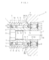
pulley unit 1 is arranged in a part which couples the driving part of an engine with a power generatingrotary shaft 3 of thealternator 2. Thepulley unit 1 has ahollow shaft 5. Therotary shaft 3 is inserted into and is rotatably supported by a central hole of afixed housing 4 in a state where theshaft 3 protrudes from an end face of thehousing 4. - The
hollow shaft 5 is fitted on the outside of the above-mentioned protruding part of therotary shaft 3 so as to be rotatable as an integral unit therewith. Apulley 10 is fitted on the outside of thehollow shaft 5 via a one-way clutch 6 , a deep groove ball bearing 7 arranged in analternator 2 side, and a roller bearing 8 arranged in the opposite side to the deep groove ball bearing 7 (any one of them is one example of a rolling bearing). A power transmission V-ribbedbelt 9 to which motive power from the engine is transmitted is wound around thepulley 10. That is, thepulley 10 is fitted on the outer diameter side of thehollow shaft 5 in a state where thepulley 10 makes anannular space 11. Wave-like grooves into which concavity and convexity of the inner peripheral face of thebelt 9 are fitted are formed on the outer peripheral face of thepulley 10. - The one-
way clutch 6 is for switching between a state where thepulley 10 and thehollow shaft 5 are rotated as an integral unit and a state where they are relatively rotated and is arranged at a central position in the shaft center direction of theannular space 11 in which thepulley 10 and thehollow shaft 5 oppose each other. The one-way clutch 6 has aroller 12 as a rolling element, as well as the inner ring raceway track of theroller 12 corresponds to the outer peripheral face of thehollow shaft 5 while the outer ring raceway track thereof corresponds to the inner peripheral face of thepulley 10. In addition, the one-way clutch 6 further has anannular roller retainer 13 made of a synthetic resin and anelliptical coil spring 14 having a function of biasing theroller 12 toward a narrow side (lock side) of a wedge-like space, which is not shown. Theroller 12 is biased toward the lock side so that the one-way clutch 6 switches to a locked state where thepulley 10 and thehollow shaft 5 are rotated as an integral unit, while theroller 12 is moved toward the opposite side to the lock side so that the one-way clutch 6 switches to a free state where thepulley 10 and thehollow shaft 5 are relatively rotated. - In the ball bearing 7, the inner ring raceway track of
balls 16 corresponds to the outer peripheral face of thehollow shaft 5 while the outer ring raceway track thereof corresponds to the inner peripheral face of thepulley 10, and the ball bearing 7 has aretainer 17. In the roller bearing 8, the inner ring raceway track of aroller 8a corresponds to the outer peripheral face of thehollow shaft 5 while the outer ring raceway track thereof corresponds to the inner peripheral face of thepulley 10, and the roller bearing 8 has aretainer 15. - These ball bearing 7 and roller bearing 8 are arranged in the
annular space 11 so as to support thehollow shaft 5 and thepulley 10 so that they can rotate relatively. -
Seal members 18 for sealing theannular space 11 are attached to the outsides of the respective roller bearing 8 and ball bearing 7 in theshaft center direction 26. Theseseal members 18 are composed ofannular core bars 19 andelastic bodies 20 covering the outsides of theannular core bars 19, and one end sides, of theelastic bodies 20 in the radial direction thereof are fixed to the inner diameter face of thepulley 10 while the other end sides thereof correspond toseal lips 21 to be in contact with the outer peripheral face of thehollow shaft 5. - An operation groove 23 into which a tool (e.g. , a hexagon wrench) for rotating the
hollow shaft 5 is fitted is formed in the free end side of acentral hole 22 of thehollow axis 5, and afemale screw part 25 into which amale screw part 24 formed on the halfway of therotary shaft 3 is screwed is formed on the halfway of thecentral hole 22. - An insert
recessed spot 30 is formed on the inner periphery of the opening side area in the central hole of thehousing 4 so that the end part of thepulley unit 1 side of thehousing 4 and the end part of thehousing 4 side of thepulley unit 1 are overlaid in the radial direction. Regarding this insertrecessed spot 30, a small diameter recessedportion 27 in a ball bearing 40 side of thehousing 4 and a large diameter recessedportion 28 of thepulley unit 1 side are formed into annular shapes via astepped face 29. The end part of thepulley unit 1 is constructed so as to be inserted into the insert recessedspot 30. - The ball bearing 40 of the
housing 4 is composed of anouter ring member 41 fitted into thehousing 4, aninner ring member 42 fitted on therotary shaft 3,balls 43 as rolling elements, aretainer 44 for theballs 43, and sealmembers 45 of both sides. - An end face of the
hollow shaft 5 abuts a side face of theinner ring 42 of the ball bearing 7 of thehousing 4, an end part of thepulley 10 is formed into a relative shape with a step along thestepped face 29, and afine gap 31 is formed between an end part of thepulley unit 1 and an end part of thehousing 4. Thisfine gap 31 constitutes a non-contact sealing part. - In this case, a non-contact seal member is formed by the
stepped face 29 in the end face of thehousing 4 and the end part of thepulley 10 along thestepped face 29. - In the
pulley unit 1 having the structure described above, the one-way clutch 6 becomes the locked state or the free state in accordance with rotation speed differences between thepulley 10 and thehollow shaft 5, and power is transmitted from thepulley 10 to thehollow shaft 5 or is interrupted. When the one-way clutch 6 becomes the free state, thehollow shaft 5 keeps rotation by the rotation inertial force thereof. - In order to attach the
pulley unit 1 to therotary shaft 3 for power generation, thepulley unit 1 is thrust onto the power generatingrotary shaft 3 until thefemale screw part 25 abuts themale screw part 24. Then, a tool is fitted into theoperation groove 23 of thehollow shaft 5 so that the tool is rotated. Thehollow shaft 5 plays a function of a nut, and thepulley unit 1 itself moves toward thehousing 4 side. Thehollow shaft 5 is rotated by the tool until thehollow shaft 5 is pressed against theinner ring 42 of the ball bearing 7 of thealternator 2 at a predetermined pressure so as to ensure thefine gap 31 between the end part of thepulley unit 1 and the end part of thehousing 4. - By attaching the
pulley unit 1 to thealternator 2 in such a manner, the end part of thepulley unit 1 overlaps theshaft center direction 26 at the end part of thehousing 4, that is, at the insertrecessed spot 30. - Since the insert
recessed spot 30 having thestepped face 29 is provided on the end part of thehousing 4 as described above, and since the end part of thepulley unit 1 is formed into a shape along the insertrecessed spot 30 having thestepped face 29, thefine gap 31 for the non-contact sealing part is provided therebetween. When thepulley 10 rotates in accordance with the rotation of thebelt 9, a labyrinth function works by thefine gap 31, and it can be prevented that water or other foreign matters invades thefine gap 31 from the outside. Thus, the life of thepulley unit 1 or the ball bearing 7 of thealternator 2 can be prolonged. - The insert
recessed spot 30 is formed on the end part of thehousing 4, and thepulley unit 1 is attached to thealternator 2 so that the end part of thepulley unit 1 is inserted into the inset recessedspot 30. Thus, even when thepulley unit 1 has the ball bearing 7, the roller bearing 8 and the one-way clutch 5 and thereby is long in theshaft center direction 26 compared with a solid pulley, the length of the whole apparatus can be shortened in theshaft center direction 26 by that part, and thus saving space can be realized compared with a conventional attaching structure of this type. - The example of the case described above corresponds to a case where the diameter of the
pulley 10 is relatively small since the end part of thepulley unit 1 overlaps the end part of thehousing 4 as described above. - Next, other examples regarding a fixing structure of a pulley unit are explained referring to FIG. 2 and the following drawings thereof.
- First, referring to FIG. 2, this
pulley unit 1 is useful for a case where the diameter of thepulley 10 is relatively large. An annular protrudedportion 35 protruding toward theshaft center direction 26 is formed on the end part of thehousing 4. A recessedportion 36 into which the protrudedportion 35 is fitted via thefine gap 31 for the non-contact sealing is formed on the end face of thepulley 10. - The outer peripheral faces of the protruded
portion 35 and the recessedportion 36 correspond to tilted faces tilted to thepulley unit 1 side relative to theshaft center direction 26, and the inner peripheral faces of the protrudedportion 35 and the recessedportion 36 correspond to tilted faces tilted to the outside relative to theshaft center direction 26. - In the structure described above, when the
pulley 1 rotates, the labyrinth function works by thefine gap 31, and water or other foreign matters can be reliably prevented from invading thefine gap 31 from the outside. Thus, the life of thepulley unit 1 or theball bearing 7 of thealternator 2 can be prolonged. - In a case where the
housing 4 can be miniaturized in theshaft center direction 26, for example, in a case where an outward appearance line part shown by virtual lines of FIG. 2 can be omitted, the width of the apparatus in theshaft center direction 26 can be miniaturized. - Referring to FIG. 3, the
pulley unit 1 lies adjacent to thealternator 2 in the shaft center direction. Therefore, the end face of thealternator 2 side of thepulley 10 lies fairly adjacent to the outer peripheral face of thehousing 4. - Accordingly, the gap between the end face of the
pulley 10 and the outer peripheral face of thehousing 4 is relatively narrow, having a certain extent of path length in the radial direction, whereby the gap has a function as a labyrinth. - The
hollow shaft 5 enters a throughhole 51 formed in thehousing 4 in a state where the end face of thehollow shaft 5 abuts the end face of theinner ring 42 of theball bearing 40 that rotatably supports therotary shaft 3 in thehousing 4. - A gap space portion S is annularly formed between an outer
peripheral face 27 of thehollow shaft 5 and an inner peripheral face of the throughhole 51, and this gap space portion S communicates with the outside via agap 50. - An
annular seal member 52 made of metal or elastic rubber is fitted on an end part of the outer periphery of thehollow shaft 5 so as to fill a part close to theball bearing 40 in the gap space portion S. - A fine space is formed between the outer peripheral face of the
annular seal member 52 and the throughhole 51 so as to construct a labyrinth seal portion L. - Therefore, since the labyrinth seal portion L is provided, even when water or foreign matters such as dust invades to the gap space portion S from the outside via the
gap 50, such foreign matter can be prevented from invading to theball bearing 40. - Referring to FIG. 4, in a case of this
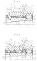
pulley unit 1, anannular seal member 53 made of metal or elastic rubber is fitted on the outer periphery of thehollow shaft 5 covering approximately whole area in the shaft center direction in the gap space portion S so as to construct the labyrinth seal portion L in the fine gap between the outer peripheral face of theannular seal member 53 and the inner peripheral face of the throughhole 51. - In this case, since the gap space portion S becomes the state where the portion S is filled with the
annular seal member 53 covering approximately whole area in the shaft center direction, invasion to theball bearing 40 by a foreign matter can be further prevented by means of the labyrinth seal portion L. - Referring to FIG. 5, in a case of this
pulley unit 1,annular seal members hollow shaft 5 while therespective members ball bearing 40 and a part of thepulley 10 side in the shaft center direction in the gap space portion S so as to constitute a labyrinth seal portion L1 in a fine gap between the outer peripheral face of theannular seal portion 54 and the inner peripheral face of the throughhole 51 and a labyrinth seal portion L2 in a fine gap between the outer peripheral face of theannular seal portion 55 and the inner peripheral face of thepulley 10. - In this case, prevention of invasion of a foreign matter to the
ball bearing 40 can be achieved by means of the labyrinth seal portion L1, and prevention of invasion of a foreign matter to theball bearing 7, the one-way clutch 6, and the like in thepulley unit 1 from the gap space portion S side can be achieved by means of the labyrinth seal portion L2. - In the embodiments described above, although shown is a structure that an annular seal member is provided on the hollow shaft and that a fine gap of a labyrinth seal portion is provided between the housing and the annular seal member, the annular seal member may be provided on the housing side, and the fine gap of the labyrinth seal portion may be formed between opposing faces of the hollow shaft and the annular seal member.
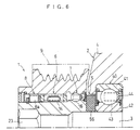
- Referring to FIG. 6, in a case of this
pulley unit 1, the end face of thehollow shaft 5 and the end face of thepulley 10 in thealternator 2 side are constructed to be approximately flush, a gap space portion S is formed so as to be surrounded by the end face of thehollow shaft 5, theball bearing 40, and the outer peripheral face of the power generatingrotary shaft 3, anannular seal member 56 constructed so as to fill approximately the whole space of the gap space portion S is fitted on the outside of the power generatingrotary shaft 3, and a labyrinth seal portion L is constructed by the fine gap between the outer peripheral face of theannular seal member 56 and inner peripheral face of the throughhole 51. - In this case, by means of the labyrinth seal portion L, prevention of invasion of a foreign matter to the
ball bearing 40 can be achieved, as well as invasion of a foreign matter to theball bearing 7, the one-way clutch 6, and the like in thepulley unit 1 through the gap space portion S side can be prevented. - As shown in FIG. 6, in the structure that the gap space portion S is formed between the end face of the
hollow shaft 5 and theball bearing 40 to be surrounded by the outer peripheral face of the power generatingrotary shaft 3, also included in the present invention are structures that (a) in the gap space portion S, theannular seal member 56 is arranged to come near to one side of theball bearing 40 relative to thehousing 4 of the power generatingrotary shaft 3, (b) in the gap space portion S, theannular seal member 56 is constructed covering approximately whole area between thepulley unit 1 and thealternator 2 in the shaft center direction so as to form a fine gap, and (c) a second annular seal member distinct from theannular seal member 56 is provided to be fixed on either side of the hollow shaft or the pulley. - Also included is a case where the
annular seal member 56 is fixed on thehousing 4 and the gap space portion is provided between the pulley unit and the housing of an auxiliary machine and around an input shaft. Further, the annular seal member may be divided for a plurality of places of a place close to the pulley unit in the shaft center direction in the gap space portion and a place close to a bearing device for an input shaft of the housing. - In the respective embodiments described above, although shown is a structure that the outer rings and the inner rings of rolling bearings provided in both sides of a one-way clutch serve for the respective pulley and hollow shaft as an integral unit, the outer rings and the inner rings of the rolling bearings may be formed as separate bodies distinct from the pulley and the hollow shaft.
- While there has been described what is at present considered to be preferred embodiments of this invention, it will be understood that various modifications may be made therein, and it is intended to cover in the appended claims all such modifications as fall within the true spirit and scope of this invention.
Claims (2)
- A pulley unit comprising:wherein a housing side end portion of said pulley (10) is formed into such a shape as to be able to face an end portion of said housing (4) with a narrow space functioning as a non-contact seal; a gap space portion (S) in annularly formed among said hollow shaft (5), said pulley (10) and said housing (4); and said gap space portion (S) is filled with an annular member (53).a hollow shaft (5) fixed to the outside of a protruding part of a rotary shaft (3) protruding from a central hole of a housing (4);a pulley (10) fitted on the outer diameter side of said hollow shaft (5) in a state where an annular space (11) is formed;a one-way clutch (6) which is arranged in said annular space an switches between a state where said hollow shaft (5) and said pulley (10) are rotated as an integral unit and a state where said hollow shaft (5) and said pulley (10) are relatively rotated;at least one rolling bearing (7, 8) which is arranged in said annular space (11) and supports said hollow shaft (5) and said pulley (10); andseal members (18, 19) for sealing said annular space, said members (18, 19) being attached to the axial outside of said rolling bearing (7, 8);
- A pulley unit comprising:wherein a housing side end portion of said pulley (10) is formed into such a shape as to be able to face an end portion of said housing (4) with a narrow space functioning as a non-contact seal; a gap space portion (S) is annularly formed among said hollow shaft (5), said pulley (10) and said housing (4); and an annular member (52, 53, 54, 55, 56) is provided so as to function as a non-contact seal in said gap space portion (S).a hollow shaft (5) fixed to the outside of a protruding part of a rotary shaft (3) protruding from a central hole of a housing (4);a pulley (10) fitted on the outer diameter side of said hollow shaft (5) in a state where an annular space (11) is formed;a one-way clutch (6) which is arranged in said annular space (11) and switches between a state where said hollow shaft (5) and said pulley (10) are rotated as an integral unit and a state where said hollow shaft (5) and said pulley (10) are relatively rotated;at least one rolling bearing (7, 8) which is arranged in said annular space and supports said hollow shaft (5) and said pulley (10); andseal members (18, 19) for sealing said annular space, said members (18, 19) being attached to the axial outside of said rolling bearing (7, 8);
Applications Claiming Priority (5)
| Application Number | Priority Date | Filing Date | Title |
|---|---|---|---|
| JP2000326778A JP3785316B2 (en) | 2000-10-26 | 2000-10-26 | Pulley unit mounting structure |
| JP2000326778 | 2000-10-26 | ||
| JP2001186253 | 2001-06-20 | ||
| JP2001186253 | 2001-06-20 | ||
| EP01125546A EP1215416B1 (en) | 2000-10-26 | 2001-10-25 | Fixing structure of a pulley unit |
Related Parent Applications (2)
| Application Number | Title | Priority Date | Filing Date |
|---|---|---|---|
| EP01125546.0 Division | 2001-10-25 | ||
| EP01125546A Division EP1215416B1 (en) | 2000-10-26 | 2001-10-25 | Fixing structure of a pulley unit |
Publications (3)
| Publication Number | Publication Date |
|---|---|
| EP1452776A2 true EP1452776A2 (en) | 2004-09-01 |
| EP1452776A3 EP1452776A3 (en) | 2006-03-15 |
| EP1452776B1 EP1452776B1 (en) | 2011-08-17 |
Family
ID=26602817
Family Applications (2)
| Application Number | Title | Priority Date | Filing Date |
|---|---|---|---|
| EP01125546A Expired - Lifetime EP1215416B1 (en) | 2000-10-26 | 2001-10-25 | Fixing structure of a pulley unit |
| EP04007035A Expired - Lifetime EP1452776B1 (en) | 2000-10-26 | 2001-10-25 | A pulley unit |
Family Applications Before (1)
| Application Number | Title | Priority Date | Filing Date |
|---|---|---|---|
| EP01125546A Expired - Lifetime EP1215416B1 (en) | 2000-10-26 | 2001-10-25 | Fixing structure of a pulley unit |
Country Status (3)
| Country | Link |
|---|---|
| US (1) | US6676548B2 (en) |
| EP (2) | EP1215416B1 (en) |
| DE (1) | DE60121906T2 (en) |
Families Citing this family (29)
| Publication number | Priority date | Publication date | Assignee | Title |
|---|---|---|---|---|
| KR20120099786A (en) * | 2002-07-26 | 2012-09-11 | 리텐스 오토모티브 파트너쉽 | Decoupler assembly |
| KR101068335B1 (en) * | 2003-02-04 | 2011-09-28 | 리텐스 오토모티브 파트너쉽 | Crankshaft torque modulator |
| JP2007506056A (en) * | 2003-09-22 | 2007-03-15 | リテンズ オートモーティヴ パートナーシップ | Crankshaft decoupler |
| JP4540974B2 (en) * | 2003-12-16 | 2010-09-08 | Ntn株式会社 | Auxiliary machine belt tension adjuster |
| US6986344B2 (en) * | 2004-02-13 | 2006-01-17 | Electrolux Professional Outdoor Products, Inc | Bladeshaft assembly for a powered saw or cutting machine |
| JP4412152B2 (en) * | 2004-11-11 | 2010-02-10 | 株式会社デンソー | Vehicle alternator |
| US8012053B2 (en) * | 2005-09-29 | 2011-09-06 | Dayco Products, Llc | Combination dust cover and bearing retention member |
| WO2007043650A1 (en) * | 2005-10-14 | 2007-04-19 | Jtekt Corporation | Pulley apparatus and auto-tensioner |
| US20070267529A1 (en) * | 2006-04-12 | 2007-11-22 | Pure Fishing, Inc. | Clutch Assembly For A Fishing Reel |
| US20080135356A1 (en) * | 2006-12-06 | 2008-06-12 | Yungh-Siang Lin | Transmission motor structure |
| DE102008033680B4 (en) * | 2007-09-12 | 2016-09-01 | Denso Corporation | Alternator with pulley for a vehicle |
| US8863925B2 (en) | 2010-06-25 | 2014-10-21 | Litens Automotive Partnership | Decoupler with integrated torsional vibration damper |
| WO2011160202A1 (en) | 2010-06-25 | 2011-12-29 | Litens Automotive Partnership | Overrunning decoupler |
| US20120168276A1 (en) * | 2011-01-04 | 2012-07-05 | Connard Cali | Apparatus for coupling torque |
| EP2706269B1 (en) * | 2011-11-25 | 2018-01-17 | NSK Ltd. | Rotating machine with pulley and built-in one-way clutch |
| US9140319B2 (en) | 2012-11-20 | 2015-09-22 | Litens Automotive Partnership | Decoupler with concentric clutching members |
| JP6256013B2 (en) * | 2014-01-09 | 2018-01-10 | 株式会社ジェイテクト | Pulley unit |
| US9033832B1 (en) | 2014-01-23 | 2015-05-19 | Gates Corporation | Isolating decoupler |
| US10851884B2 (en) * | 2014-03-14 | 2020-12-01 | ZPE Licensing Inc. | Super charger components |
| US9421637B2 (en) * | 2014-03-14 | 2016-08-23 | ZPE Licensing Inc. | Super charger components |
| US11041558B2 (en) * | 2014-03-14 | 2021-06-22 | ZPE Licensing Inc. | Super charger components |
| US10655723B2 (en) * | 2014-03-14 | 2020-05-19 | ZPE Licensing Inc. | Super charger components |
| US9028353B1 (en) * | 2014-03-14 | 2015-05-12 | ZPE Licensing Inc. | Super charger components |
| TWI555932B (en) * | 2014-07-14 | 2016-11-01 | 勝利工業股份有限公司 | Pulley for an alternator |
| US9291253B1 (en) | 2015-03-24 | 2016-03-22 | Gates Corporation | Isolating decoupler |
| FR3059171A1 (en) * | 2016-11-21 | 2018-05-25 | Valeo Equipements Electriques Moteur | PULLEY ASSEMBLY FOR ROTATING ELECTRICAL MACHINE |
| US10794663B2 (en) | 2017-05-11 | 2020-10-06 | ZPE Licensing Inc. | Laser induced friction surface on firearm |
| US11708886B2 (en) | 2017-09-07 | 2023-07-25 | Litens Automotive Partnership | Single spring, torsionally compliant, overrunning decoupler |
| US20190211912A1 (en) * | 2018-01-09 | 2019-07-11 | Alt America Inc. | Axial Driven Overrunning Alteration Pulleys |
Citations (5)
| Publication number | Priority date | Publication date | Assignee | Title |
|---|---|---|---|---|
| US4808082A (en) * | 1986-10-29 | 1989-02-28 | Bbc Brown Boveri Ag | Pressure wave supercharger |
| GB2268546A (en) * | 1992-07-03 | 1994-01-12 | Bosch Gmbh Robert | Sealing electric machines |
| US5334097A (en) * | 1992-01-07 | 1994-08-02 | Toyota Jidosha Kabushiki Kaisha | Toroidal type continuously variable transmission supported by a common bearing and reaction stationary shaft |
| EP0746080A1 (en) * | 1995-05-29 | 1996-12-04 | Nippondenso Co., Ltd. | Rotary-machine having water-resistant structure |
| US6095301A (en) * | 1997-09-24 | 2000-08-01 | Koyo Seiko Co., Ltd. | Pulley unit |
Family Cites Families (8)
| Publication number | Priority date | Publication date | Assignee | Title |
|---|---|---|---|---|
| JPS5721833U (en) * | 1980-07-15 | 1982-02-04 | ||
| US5163883A (en) * | 1991-12-04 | 1992-11-17 | General Motors Corporation | Pulley with integral fastener and spacer |
| JP3120668B2 (en) | 1994-11-04 | 2000-12-25 | トヨタ自動車株式会社 | Power transmission device |
| JPH08317599A (en) | 1995-05-22 | 1996-11-29 | Mitsubishi Electric Corp | Generator for vehicle |
| US6170625B1 (en) * | 1997-07-01 | 2001-01-09 | Koyo Seiko Co., Ltd. | Pulley unit |
| JPH11117758A (en) | 1997-10-13 | 1999-04-27 | Nippon Seiko Kk | Member for engine electric equipment accessory |
| JP2000240461A (en) * | 1999-02-23 | 2000-09-05 | Nsk Ltd | One-way clutch built-in type pulley device for alternator and method for preventing creak of alternator driving endless belt |
| US6394248B1 (en) * | 2000-05-31 | 2002-05-28 | Ntn Corporation | Compression spring complaint one-way over-running clutch pulley |
-
2001
- 2001-10-25 EP EP01125546A patent/EP1215416B1/en not_active Expired - Lifetime
- 2001-10-25 US US10/033,049 patent/US6676548B2/en not_active Expired - Lifetime
- 2001-10-25 DE DE60121906T patent/DE60121906T2/en not_active Expired - Lifetime
- 2001-10-25 EP EP04007035A patent/EP1452776B1/en not_active Expired - Lifetime
Patent Citations (5)
| Publication number | Priority date | Publication date | Assignee | Title |
|---|---|---|---|---|
| US4808082A (en) * | 1986-10-29 | 1989-02-28 | Bbc Brown Boveri Ag | Pressure wave supercharger |
| US5334097A (en) * | 1992-01-07 | 1994-08-02 | Toyota Jidosha Kabushiki Kaisha | Toroidal type continuously variable transmission supported by a common bearing and reaction stationary shaft |
| GB2268546A (en) * | 1992-07-03 | 1994-01-12 | Bosch Gmbh Robert | Sealing electric machines |
| EP0746080A1 (en) * | 1995-05-29 | 1996-12-04 | Nippondenso Co., Ltd. | Rotary-machine having water-resistant structure |
| US6095301A (en) * | 1997-09-24 | 2000-08-01 | Koyo Seiko Co., Ltd. | Pulley unit |
Also Published As
| Publication number | Publication date |
|---|---|
| US20020058560A1 (en) | 2002-05-16 |
| DE60121906T2 (en) | 2007-02-15 |
| DE60121906D1 (en) | 2006-09-14 |
| EP1452776B1 (en) | 2011-08-17 |
| EP1452776A3 (en) | 2006-03-15 |
| EP1215416B1 (en) | 2006-08-02 |
| EP1215416A1 (en) | 2002-06-19 |
| US6676548B2 (en) | 2004-01-13 |
Similar Documents
| Publication | Publication Date | Title |
|---|---|---|
| US6676548B2 (en) | Fixing structure of a pulley unit | |
| EP1275883B1 (en) | Pulley unit | |
| US6893368B2 (en) | Driving force transmission apparatus | |
| US6170625B1 (en) | Pulley unit | |
| US7100754B2 (en) | Pulley unit | |
| JP2005163932A (en) | Pulley unit | |
| JP4123836B2 (en) | Pulley unit sealing structure | |
| JP2002228008A (en) | Seal ring | |
| JP2003074672A (en) | Pulley unit | |
| JP3785316B2 (en) | Pulley unit mounting structure | |
| EP1041305B1 (en) | One-way clutch | |
| US7007781B2 (en) | One-way clutch unit and one-way clutch therefor | |
| JP2006258131A (en) | Rolling bearing | |
| JP3785248B2 (en) | Pulley unit | |
| JP2003004123A (en) | Pulley unit | |
| JP4617610B2 (en) | Pulley unit | |
| JPH1122753A (en) | Pulley unit | |
| JP3731703B2 (en) | Pulley unit | |
| JP3731704B2 (en) | Pulley unit | |
| JP2004190763A (en) | Rotary supporting device for pulley | |
| JP2003004124A (en) | Pulley unit | |
| JP2001090810A (en) | Pulley unit and one-way clutch used therefor | |
| JPH11280874A (en) | Pulley unit | |
| JP2001027255A (en) | Rotating machine device with creep preventing device for rolling bearing | |
| JP4461835B2 (en) | Pulley unit |
Legal Events
| Date | Code | Title | Description |
|---|---|---|---|
| PUAI | Public reference made under article 153(3) epc to a published international application that has entered the european phase |
Free format text: ORIGINAL CODE: 0009012 |
|
| 17P | Request for examination filed |
Effective date: 20040324 |
|
| AC | Divisional application: reference to earlier application |
Ref document number: 1215416 Country of ref document: EP Kind code of ref document: P |
|
| AK | Designated contracting states |
Kind code of ref document: A2 Designated state(s): DE FR GB IT |
|
| PUAL | Search report despatched |
Free format text: ORIGINAL CODE: 0009013 |
|
| AK | Designated contracting states |
Kind code of ref document: A3 Designated state(s): DE FR GB IT |
|
| RIC1 | Information provided on ipc code assigned before grant |
Ipc: F16H 7/20 20060101AFI20040705BHEP Ipc: F16H 55/49 20060101ALI20060123BHEP Ipc: F16H 55/36 20060101ALI20060123BHEP |
|
| RAP1 | Party data changed (applicant data changed or rights of an application transferred) |
Owner name: JTEKT CORPORATION |
|
| AKX | Designation fees paid |
Designated state(s): DE FR GB IT |
|
| 17Q | First examination report despatched |
Effective date: 20070720 |
|
| APBK | Appeal reference recorded |
Free format text: ORIGINAL CODE: EPIDOSNREFNE |
|
| APBN | Date of receipt of notice of appeal recorded |
Free format text: ORIGINAL CODE: EPIDOSNNOA2E |
|
| APBR | Date of receipt of statement of grounds of appeal recorded |
Free format text: ORIGINAL CODE: EPIDOSNNOA3E |
|
| APBV | Interlocutory revision of appeal recorded |
Free format text: ORIGINAL CODE: EPIDOSNIRAPE |
|
| GRAP | Despatch of communication of intention to grant a patent |
Free format text: ORIGINAL CODE: EPIDOSNIGR1 |
|
| GRAS | Grant fee paid |
Free format text: ORIGINAL CODE: EPIDOSNIGR3 |
|
| GRAA | (expected) grant |
Free format text: ORIGINAL CODE: 0009210 |
|
| RIN1 | Information on inventor provided before grant (corrected) |
Inventor name: FUJIWARA, HIDEKIC/O KOYO SEIKO CO., LTD. |
|
| AC | Divisional application: reference to earlier application |
Ref document number: 1215416 Country of ref document: EP Kind code of ref document: P |
|
| AK | Designated contracting states |
Kind code of ref document: B1 Designated state(s): DE FR GB IT |
|
| REG | Reference to a national code |
Ref country code: GB Ref legal event code: FG4D |
|
| REG | Reference to a national code |
Ref country code: DE Ref legal event code: R096 Ref document number: 60145175 Country of ref document: DE Effective date: 20111020 |
|
| PG25 | Lapsed in a contracting state [announced via postgrant information from national office to epo] |
Ref country code: IT Free format text: LAPSE BECAUSE OF FAILURE TO SUBMIT A TRANSLATION OF THE DESCRIPTION OR TO PAY THE FEE WITHIN THE PRESCRIBED TIME-LIMIT Effective date: 20110817 |
|
| PLBE | No opposition filed within time limit |
Free format text: ORIGINAL CODE: 0009261 |
|
| STAA | Information on the status of an ep patent application or granted ep patent |
Free format text: STATUS: NO OPPOSITION FILED WITHIN TIME LIMIT |
|
| 26N | No opposition filed |
Effective date: 20120521 |
|
| GBPC | Gb: european patent ceased through non-payment of renewal fee |
Effective date: 20111117 |
|
| REG | Reference to a national code |
Ref country code: DE Ref legal event code: R097 Ref document number: 60145175 Country of ref document: DE Effective date: 20120521 |
|
| PG25 | Lapsed in a contracting state [announced via postgrant information from national office to epo] |
Ref country code: GB Free format text: LAPSE BECAUSE OF NON-PAYMENT OF DUE FEES Effective date: 20111117 |
|
| PGFP | Annual fee paid to national office [announced via postgrant information from national office to epo] |
Ref country code: FR Payment date: 20141008 Year of fee payment: 14 |
|
| REG | Reference to a national code |
Ref country code: FR Ref legal event code: ST Effective date: 20160630 |
|
| PG25 | Lapsed in a contracting state [announced via postgrant information from national office to epo] |
Ref country code: FR Free format text: LAPSE BECAUSE OF NON-PAYMENT OF DUE FEES Effective date: 20151102 |
|
| PGFP | Annual fee paid to national office [announced via postgrant information from national office to epo] |
Ref country code: DE Payment date: 20191015 Year of fee payment: 19 |
|
| REG | Reference to a national code |
Ref country code: DE Ref legal event code: R119 Ref document number: 60145175 Country of ref document: DE |
|
| PG25 | Lapsed in a contracting state [announced via postgrant information from national office to epo] |
Ref country code: DE Free format text: LAPSE BECAUSE OF NON-PAYMENT OF DUE FEES Effective date: 20210501 |