EP1452471A2 - Paper-like material conveying apparatus - Google Patents
Paper-like material conveying apparatus Download PDFInfo
- Publication number
- EP1452471A2 EP1452471A2 EP03030009A EP03030009A EP1452471A2 EP 1452471 A2 EP1452471 A2 EP 1452471A2 EP 03030009 A EP03030009 A EP 03030009A EP 03030009 A EP03030009 A EP 03030009A EP 1452471 A2 EP1452471 A2 EP 1452471A2
- Authority
- EP
- European Patent Office
- Prior art keywords
- paper
- roller
- rollers
- conveying
- driven
- Prior art date
- Legal status (The legal status is an assumption and is not a legal conclusion. Google has not performed a legal analysis and makes no representation as to the accuracy of the status listed.)
- Granted
Links
Images


Classifications
-
- B—PERFORMING OPERATIONS; TRANSPORTING
- B65—CONVEYING; PACKING; STORING; HANDLING THIN OR FILAMENTARY MATERIAL
- B65H—HANDLING THIN OR FILAMENTARY MATERIAL, e.g. SHEETS, WEBS, CABLES
- B65H27/00—Special constructions, e.g. surface features, of feed or guide rollers for webs
-
- B—PERFORMING OPERATIONS; TRANSPORTING
- B65—CONVEYING; PACKING; STORING; HANDLING THIN OR FILAMENTARY MATERIAL
- B65H—HANDLING THIN OR FILAMENTARY MATERIAL, e.g. SHEETS, WEBS, CABLES
- B65H29/00—Delivering or advancing articles from machines; Advancing articles to or into piles
- B65H29/38—Delivering or advancing articles from machines; Advancing articles to or into piles by movable piling or advancing arms, frames, plates, or like members with which the articles are maintained in face contact
- B65H29/42—Members rotated about an axis parallel to direction of article movement, e.g. helices
-
- B—PERFORMING OPERATIONS; TRANSPORTING
- B65—CONVEYING; PACKING; STORING; HANDLING THIN OR FILAMENTARY MATERIAL
- B65H—HANDLING THIN OR FILAMENTARY MATERIAL, e.g. SHEETS, WEBS, CABLES
- B65H5/00—Feeding articles separated from piles; Feeding articles to machines
- B65H5/06—Feeding articles separated from piles; Feeding articles to machines by rollers or balls, e.g. between rollers
- B65H5/062—Feeding articles separated from piles; Feeding articles to machines by rollers or balls, e.g. between rollers between rollers or balls
-
- B—PERFORMING OPERATIONS; TRANSPORTING
- B65—CONVEYING; PACKING; STORING; HANDLING THIN OR FILAMENTARY MATERIAL
- B65H—HANDLING THIN OR FILAMENTARY MATERIAL, e.g. SHEETS, WEBS, CABLES
- B65H2301/00—Handling processes for sheets or webs
- B65H2301/30—Orientation, displacement, position of the handled material
- B65H2301/32—Orientation of handled material
- B65H2301/321—Standing on edge
-
- B—PERFORMING OPERATIONS; TRANSPORTING
- B65—CONVEYING; PACKING; STORING; HANDLING THIN OR FILAMENTARY MATERIAL
- B65H—HANDLING THIN OR FILAMENTARY MATERIAL, e.g. SHEETS, WEBS, CABLES
- B65H2404/00—Parts for transporting or guiding the handled material
- B65H2404/10—Rollers
- B65H2404/11—Details of cross-section or profile
- B65H2404/112—Means for varying cross-section
- B65H2404/1122—Means for varying cross-section for rendering elastically deformable
-
- B—PERFORMING OPERATIONS; TRANSPORTING
- B65—CONVEYING; PACKING; STORING; HANDLING THIN OR FILAMENTARY MATERIAL
- B65H—HANDLING THIN OR FILAMENTARY MATERIAL, e.g. SHEETS, WEBS, CABLES
- B65H2404/00—Parts for transporting or guiding the handled material
- B65H2404/10—Rollers
- B65H2404/18—Rollers composed of several layers
- B65H2404/185—Rollers composed of several layers easy deformable
-
- B—PERFORMING OPERATIONS; TRANSPORTING
- B65—CONVEYING; PACKING; STORING; HANDLING THIN OR FILAMENTARY MATERIAL
- B65H—HANDLING THIN OR FILAMENTARY MATERIAL, e.g. SHEETS, WEBS, CABLES
- B65H2701/00—Handled material; Storage means
- B65H2701/10—Handled articles or webs
- B65H2701/19—Specific article or web
- B65H2701/1916—Envelopes and articles of mail
Definitions
- This invention relates to a paper-like material conveying apparatus to convey paper-like materials in different thickness, a paper-like material conveying direction switching apparatus to reverse the conveying direction of paper-like materials in different thickness, and a paper-like material stamping apparatus to stamp paper-like materials in different thickness, and particularly relates to a paper-like material conveying apparatus, a paper-like material conveying direction switching apparatus and a paper-like material stamping apparatus to process paper-like materials in different thickness such as postal matters, bankbooks, etc.
- a separation apparatus to take out copy paper from a paper cassette one by one in a copier is known as an apparatus to process paper-like materials by pinching them with a pair of rollers as disclosed in the Japanese Patent Disclosure No. 8-99734.
- This apparatus uses elastic rollers that are in the three-layer structure as paper separation rollers.
- These elastic rollers are in such structure that, for instance, a porous resin layer is formed for the first layer on the roller shaft, an impregnated resin coated layer is formed for the second layer, and a coating resin layer is formed for the third layer.
- These elastic body rollers are arranged near the end of a paper supply cassette by pressure fitting to the paper feeding rollers. Plural sheets of copy paper are separated and taken out one by one by rotating the elastic rollers in the direction reverse to the copy paper take-out direction while rotating the feeding roller in the copy paper take-out direction.
- the elastic roller described above is designed for the purpose of taking out thick copy paper uniformly from a paper supply cassette by separating sheets one by one and is not designed by assuming to clamp and convey paper-like materials in different thickness such as postal matters, bankbooks, etc. Therefore, for example, even when these elastic rollers are adopted for a postal matter processing apparatus, the rollers are not able to correspond to change in thickness of postal matters and do not function normally.
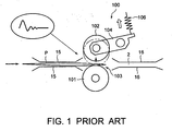
- a conventional conveying apparatus 100 shown in FIG. 1 has a drive roller 101 arranged rigidly at the underside of a conveying path 2 and a driven roller 102 arranged at the upper side of conveying path 2.
- Driven roller 102 is attached rotatably to the end of an arm 104 that is rotatably attached to a frame and pressed by a spring 106 toward drive roller 101.
- a paper-like material take-out apparatus to take out paper-like materials by separating them one by one is known as an apparatus to take out stacked paper-like materials on a conveying path as shown in the Japanese Patent Disclosure No. 2003-109061.
- This apparatus has a pick-up roller to contact paper-like materials at one end in the stacking direction and a separating portion to separate the taken out paper-like materials one by one by rotating the pick-up roller.
- the separation portion has a take-out roller arranged at one side of a conveying path and a reversing roller pressed by the take-out roller through the conveying path.
- a pinch roller is arranged to the drive roller under pressure through the conveying path.
- the pinch roller is compressed to the drive roller by a spring.
- a paper-like material conveying apparatus comprising a drive roller which is given with a driving force, rotated and driven; and a driven roller arranged rotatably following the rotation of the drive rollers, the driven roller including a first layer formed with a solid elastic material that is in contact with the drive roller and a second layer formed with a foam elastic material that is formed at the inside from the first layer, wherein paper-like materials conveyed into the nip between the drive roller and the driven roller are pinched, conveyed and carried out.
- a paper-like material conveying direction switching apparatus comprising a drive roller which is given with a drive force, rotated and driven in both the forward and reverse directions; and a driven roller arranged rotatably following the rotation of the drive rollers, the driven roller including a first layer formed with a solid elastic material that is in contact with the drive roller and a second layer formed with a foam elastic material that is formed at the inside from the first layer, wherein paper-like materials in non-uniform thickness conveyed into the nip between the drive roller and the driven roller are pinched, conveyed and stopped and then, the drive roller is counter-rotated and the paper-like materials are carried out in the reverse direction.
- a paper-like material stamping apparatus comprising a cylindrical stamp having a convex plate on the outer surface, which is given with a driving force and rotates; an ink supply portion to supply ink to the outer surface of the cylindrical stamp; and a platen roller arranged on the outer surface of the cylindrical stamp in the non-contact state via a prescribed gap, the platen roller including a first layer formed with a solid elastic material and a second layer formed with a foam elastic material that is formed at the inside from the first layer, and the platen roller being given with a driving force and rotated in the same direction as the cylindrical stamp, wherein a mark is stamped on the surfaces of paper-like materials in non-uniform thickness carried into the gap by contacting and rotating the cylindrical stamp thereon.
- a paper-like material conveying apparatus comprising plural drive rollers to contact the same surfaces of paper-like materials taken out on a conveying path and rotate in the conveying direction at the same peripheral velocity; and plural driven rollers rigidly arranged in contact with plural drive rollers rotatably following the rotation of the drive rollers, respectively through the conveying path and allow to accept paper-like materials conveyed into nips between the driven rollers and the opposed drive rollers by elastically deforming and rotate independently each other.
- a paper-like material conveying direction switching apparatus comprising plural drive rollers which contact the same surfaces of paper-like materials taken out on a conveying path and rotate in the same direction at the same peripheral velocity; and plural driven rollers which are arranged rigidly to contact the plural drive rollers through the conveying path, rotatably following the rotation of the drive rollers, allow to accept paper-like materials to the nips between the driven rollers and the opposed drive rollers by elastically deforming and rotate each other independently, wherein paper-like materials conveyed into the plural nips are conveyed while pinched and stopped and then, the plural drive rollers are counter-rotated and the paper-like materials are carried out in the reverse direction.
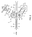
- FIG. 2 shows a schematic structure of a conveying apparatus 1 (paper-like material conveying apparatus) involved in a first embodiment of this invention.
- This conveying apparatus will be explained here taking such postal matters P as 0.15 to 6 mm thick envelops, postcards, envelops containing photographs, vinyl envelops as examples. Further, the using ambient temperature of this conveying apparatus 1 was assumed at 0 to 40°C.
- Conveying apparatus 1 has a conveying path 2 for conveying postal matters P in the direction of an arrow mark T in FIG. 2, a drive roller 4 arranged at one side of conveying path 2 (the lower side in FIG. 2), and a driven roller 6 arranged at the other side of conveying path 2 (the upper side in the figure).
- Driven roller 6 is arranged at a position opposing to drive roller 4 via conveying path 2 and deformed as press fit to drive roller 4.
- a rotational shaft 4a of drive roller 4 is attached to a frame 1a of conveying apparatus 1 rotationally and rigidly.
- An endless timing belt 11 is wound round a pulley 4b that is fixed to rotational shaft 4a of drive roller 4.
- Timing belt 11 is connected to a motor 13 via a pulley 12. When motor 13 is driven, drive roller 4 is rotated in the arrow mark direction (the clockwise direction) in FIG. 2 at a specified speed.
- Rotational shaft 6a of driven roller 6 is installed to frame 1a rotatably and rigidly. That is, rotational shaft 6a is attached with a housing 14 that has plural bearings (not shown) and this housing 14 is rigidly attached to frame 1a. Driven roller 6 is in contact with drive roller 4 and rotated following the rotation of drive roller 4.
- the center distance of drive roller 4 and driven roller 6 is so set that both are press fit via conveying path 2. That is, because two rollers 4 and 6 are arranged rigidly against frame 1a, a thrusting force is produced between them when driven roller 6 is elastically deformed as shown.
- the center distance is set so that a deformed amount of driven roller 6 becomes 0.5 mm in the state where drive roller 4 and driven roller 6 are press fit.
- This deforming amount denotes a length of the center distance that is made short from the contacting state of two rollers 4 and 6.
- Driven roller 6 has an elastic dual layer structure.
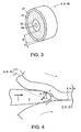
- a first layer at the outside contacting drive roller 4 is formed by a rubber 21 (a solid elastic material) and a second layer at the inner side is formed by a sponge 22 (a foam elastic material) as shown in an enlarged view in FIG. 3.
- an aluminum core metal 23 is provided at the outside of rotational shaft 6a and sponge 22 is provided at the outside of core metal 23.
- LL Rubber B type an independent foam urethane sponge manufactured by Kyowa Giken Co., Ltd. was adopted for sponge 22.
- This independent foam urethane sponge has a compression set less than 3% specified in JIS K 6254, a tear strength more than 2 kN/m specified in JIS K 6252, and Asker C Hardness 30 (equal to JIS K 6523 type).
- Rubber 21 is provided at the outside of sponge 22.
- This rubber 21 is HAN60 (natural rubber) manufactured by Hitachi Cable Ltd.) and its rubber hardness is 60 (JIS K 6253 A type).
- coefficient of rubber generally varies depending upon mating material, ambient temperature and relative velocity and it is necessary to take these conditions into consideration sufficiently when selecting rubber 21.
- coefficient of dynamic friction more than 0.8 in a range of relative velocity less than 200 mm/s can be maintained for an extended period when the above-mentioned HAN60 manufactured by Hitachi Cable Ltd. is used.
- NBR series (nitrile rubber system) manufactured by Hokushin Corporation may be used in addition to HAN60 as materials for rubber 21.
- Urethane Sponge No. 15 manufactured by Hokushin Corporation is also usable.
- the surface roughness of core metal 23 is increased by the sand blast processing and sponge 22 is bonded to the outer surface of core metal 23 using a vulcanizing agent in this embodiment.
- elastic bonding agents as epoxy bonding agent such as Araldite, PM155 manufactured by Cemedine Co. Ltd. may be used.
- rubber 21 was bonded to the outer surface of sponge 22 using a bonding agent; that is, Tyrite 7650 ("Tyrite” is the trademark of Lord corporation) used jointly with Chemlok 7701 (a primer agent) ("Chemlok” is the trademark of the Lord Corporation).
- This bonding agent may be used for bonding sponge 22 and core metal 23.
- sponge 22 may be fitted into core metal 23 by making the outer diameter of core metal 23 larger than the inner diameter of sponge 22 by about 10% without using a bonding agent for fixing core metal 23 and sponge 22.
- the thickness t1 of rubber 21 was 2 mm
- thickness t2 of sponge 22 was 13 mm
- the diameter of core metal 23 was 20 mm
- the diameter of driven roller 6 was 50 mm.
- the width of driven roller 6 was 15 mm.
- drive roller 4 was formed with the same rubber material as that of rubber 21 of driven roller 6.
- driven roller 6 is arranged rigidly to drive roller 4 in the press fit state as described above, driven roller 6 does not leap up from conveying path 2 when a postal matter P is rushed into nip
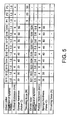
- driven roller 6 and a postal matter P when a postal matter P is rushed into nip 5 will be reviewed referring to FIG. 4. Further, in the state before a postal matter P arrives at nip 5, driven roller 6 is in contact with drive roller 4, a driving force is transmitted from the drive roller 4 and driven roller 6 is rotating in the direction of the arrow mark shown in FIG. 4 following the rotation of the drive roller 4.
- a postal matter P is conveyed in the arrow direction T by the conveying force F based on the rotation of drive roller 4 and the conveying force F' based on the rotation (the driven rotation) of driven roller 6. Therefore, if a resultant force of the conveying forces F and F' acting on a postal matter P was sufficiently larger than the reaction force Rsin ⁇ , a postal matter P is normally conveyed but if the conveying forces F and F' become small, the conveying becomes defective.
- a method to make elasticity of driven roller 6 weak is also considered so as to make the reaction force Rsin ⁇ small to obtain the normal conveying performance. According to the results of tests that will be described later, a good result was obtained when a sponge having a compression set less than 5% specified in JIS K 6254, Asker C (or JIS K 6253 type) hardness less than 40 and the thickness t2 more than 1.8 times of the most thick postal matter P (6 mm in this embodiment) of postal matters subject to process was used as sponge 22 that governs elasticity of driven roller 6.
- the compression set of sponge 22 largely affects the maintenance of the performance to deform following a postal matter P.
- the compression set specified in JIS K 6254 exceeds 5%, the permanent set results by a load caused from a thrusting force when not operated and a load when conveying especially thick postal matters P and the sponge could not be kept in the circular shape. As a result, a required thrusting force could not be given to especially thin postal matters P and postal matters could not be conveyed normally.
- hardness and thickness of sponge 22 become conditions required for obtaining the deforming performance following to postal matters P and proper thrusting force by their interaction.
- hardness is too high or thickness is too thin, the following deformation becomes difficult, defective conveying results or postal matters P and drive roller 4 (including peripheral members) may be damaged.
- 1,000 postal matters P in the thickness of 0.15 to 6 mm, the weight range of 2 to 60 g (thickness and weight were allocated so that thick postal matters become equivalent to heavy postal matters) were provided as test articles.
- These 1,000 postal matters were conveyed successively through the above-mentioned conveying apparatus 1 at a conveying velocity 3.6 m/s and a conveying interval 100 mm, and a deviation (standard deviation) in the conveying interval among postal matters passed through conveying apparatus 1 was checked.
- the conveying interval was measured based on a time difference to detect the passage of a postal matter P by sensors 17 and 18 arranged before and behind nip 5.
- HAN60 rubber 21 manufactured by Hitachi Cable Ltd. (a coefficient of dynamic friction more than 0.7 can be obtained even at an ambient temperature 0°C) was used as shown in FIG. 5, a coefficient of dynamic friction of driven rollers S11 to S19 is 1.0.
- driven rollers S21 to S29 an n urethane rubber having a coefficient of dynamic friction about 0.6 was used for rubber 21.
- the outer diameter of driven rollers S11 ⁇ S19 and S31 to S20 was unified at 50 mm and the diameter of core metal 23 was unified at 20 mm.
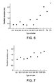
- the standard deviation of five driven rollers S11, S12, S14, S15 and S17 is about 0.5 ms as shown in FIG. 6 and a good result is presented.
- the thickness of rubber 21 of these driven rollers is all less than 4 mm. That is, the thickness of sponge 22 (15 to 4 mm) against maximum 6 mm thick postal matters is more than 1.8 times and the thickness of rubber 21 is less than 1/2 of the thickness of sponge 22.
- the thickness of rubber 21 of three driven rollers S13, S16 and S19 is 6 mm and does not satisfy the above-mentioned conditions. Therefore, when conveying a relatively thick postal matter P, the driven roller could not deform following the postal matter P and a variance of conveying interval was generated, and the standard deviation of these driven rollers was larger than the above-mentioned five driven rollers S11, S12, S14, S15 and S17. In particular, from the detailed analysis it is seen that this standard deviation becomes remarkably large according to thickness of postal matter P.
- driven roller S18 has rubber 21 that is 4 mm thick and clears the required condition
- sponge 22 has a relatively higher hardness ofAsker C 50 and driven roller S18 could not deform following a postal matter P. That is, even when the thickness of rubber 21 is made thin, driven roller S18 cannot deform following a postal matter P when the hardness of sponge 22 becomes hard and it is seen that the defective conveyance results anyway.
- driven rollers 102 that were tested by incorporating in conventional conveying apparatus 100 shown in FIG. 1 are shown as P1, P2 and P3. These driven rollers P1 to P3 are not in the two layer structure, formed 4 mm thick with pure rubber material having a coefficient of dynamic friction 1.0.
- driven roller 6 in the above-mentioned two-lay structure and arrange it rigidly by press fitting to driven roller 4 as in conveying apparatus 1 in the first embodiment described above. Further, it is seen that the center distance of driven rollers 6 and 4 is set at an adequate distance and the thrusting force is set at an adequate value.
- driven rollers S11, S12, S14 and S15 were set in conveying apparatus 1, damages of the component units and postal matters P were not recognized. That is, these four driven rollers S11, S12, S14 and S15 satisfied the conditions to display a good conveying performance.
- this inventor et al. conducted the endurance test shown below to investigate tear strength and durability of sponge 22. That is, driven rollers S11', S12', S14' and S15' with Kyowa Giken made LL rubber A type sponge 22' replaced for sponge 22 of four driven rollers S11, S12, S14 and S15 which could obtain a good conveying performance as described above were prepared. Then, an endurance test was conducted to convey plural postal matters P consecutively for 1,000 hours by incorporating these driven rollers S11', S12', S14' and S15' in conveying apparatus 1, respectively.
- Harness of sponges 22 of driven rollers S11 and S12 caused crack is smaller than that of the other same type of driven rollers S14 and S15.
- tear strength tends to become weak. That is, it can be said that a reason for cracking is tear strength and a sponge having low tear strength is liable to cause crack.
- sponge 22 of driven rollers can be improved when a sponge of JIS K 6252 tear strength 8 kN/m or above is used. Further, for materials of sponge 22, polyolefin foam material PE-LITE (Trademark) RL Series manufactured by INOAC CORPORATION and Hokushin Corporation made urethane sponge No. 15 are effectively usable.
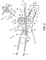
- a conveying direction switching apparatus 30 paper-like material conveying direction switching apparatus involved in the second embodiment of this invention will be explained referring to FIG. 8. Further, component elements that function similarly to those of conveying apparatus 1 in the first embodiment will be assigned with the same reference numerals and the detailed explanation thereof will be omitted. Further, this conveying direction switching apparatus 30 is to processes postal materials P in different thickness.
- Conveying direction switching apparatus 30 has drive rollers 4 and driven rollers 6 which are rotated in the forward and reverse directions by a motor 13'. Rollers 4 and 6 are in the same structure as those in the first embodiment and press fit each other with conveying path 2 put between them. Further, conveying direction switching apparatus 30 has a guide plate 31 extending along the lower surface of conveying path 2 via nip 5 put between two rollers 4 and 6.
- conveying direction switching apparatus 30 is provided with a conveying apparatus 35 which feeds a postal matter P toward nip 5 (in the arrow direction T1 in FIG. 8), receives a postal matter P sent out in the reverse direction (in the arrow direction T2) from nip 5 and conveys a received postal matter in the arrow direction T2.
- Conveying apparatus 35 has plural conveying rollers 36 and plural endless conveying belts 37 stretched by wounding round these conveying rollers 36.
- Drive roller 4 is so controlled as to repeat the forward and reverse rotations according to the charge timing of postal matters P.
- driven roller 6 in this embodiment is light in weight as the second layer is constructed using sponge 2 and the moment of inertia can be made small. Thus, a load at the time of rotation can be reduced.
- the weight of driven roller 6 is within a range of 20 to 26 g including the weight of core metal 23 and a driven roller can be made to a weight below 75% of a solid rubber roller.
- the paper feed test was also conducted on conveying direction switching apparatus 30 of this embodiment by charging plural postal matters P under the same conditions as conveying apparatus 1 in the first embodiment. That is, driven rollers S11 to S19 and S21 to S29 shown in FIG. 5 sere set in conveying direction switching apparatus 30, 1,000 postal matters P in the above-mentioned thickness and weight were charged, and variance in the conveying interval (the standard deviation) of postal matters P was checked. The results are shown in FIG. 9 and FIG. 10.
- the standard deviations of six driven rollers S11, S12, S14, S15, S17 and S18 are in the range of 0.7 to 1.1 ms and good results are shown.
- the thickness of rubber 21 of these driven rollers was all below 4 mm. That is, the thickness (15 to 4 mm) is more than 1.8 times against postal matters P in maximum thickness 6 mm and the thickness of rubber 21 is below 1/2 of the thickness of sponge 22.
- this type of conveying direction switching apparatus 30 is normally incorporated at one or two points.
- the conveying interval is different largely. This is a problem in the structure to reverse postal matters P and a tolerance of the difference in conveying interval may be set larger than that of conveying apparatus 1 equipped with plural conveying direction switching apparatus. Therefore, when the standard deviation is in a range of 0.6 to 1.1 ms as shown by the test result described above, it is considered that a good processing performance is presented.
- rubber 21 of driven rollers S14, S16 and S19 is 6 mm thick but the standard deviation was larger than driven rollers S11, S132, S14, S15, S17 and S18. That is, the condition of this invention is not satisfied.
- driven rollers S13, S16 and S19 driven rollers were not able to deform following postal matters P when relatively thick postal matters P are conveyed and the conveying interval was varied. Further, as rubber 21 is thick, driven rollers became heavy and the large variance resulted accordingly.
- the thickness t2 of sponge 22 more than 1.8 times of the maximum thickness of postal matter P and the thickness t1 of rubber 21 less than 1/2 of the thickness t2 of sponge 22 are required for obtaining a good reversing performance.
- driven roller 6 rigidly for drive roller 4 in the press fit state likewise paper-like material conveying direction switching apparatus 30 in the second embodiment and it is also important to set driven roller 6 and drive roller 4 at a proper center distance so as to set the thrusting force at a proper value.
- the inventor et al. confirmed that a good reversing performance is obtained when a rubber material of which coefficient of dynamic friction becomes more than 0.7 at a relative velocity difference between driven roller 6 and postal matter P below 200 mm/s is used for rubber 21.
- the hardness of sponge 22 was smaller than the same type of other rollers S14 and S15.
- the tear strength also tends to become small. That is, the reason for causing crack and deformation is the tear strength and it can be said that sponge tends to cause crack and deformation when the tear strength is small.
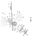
- stamping apparatus 40 (a paper-like stamping apparatus) involved in a third embodiment of this invention will be explained referring to FIG. 3. Further, component elements of this stamping apparatus functioning similarly to conveying apparatus 1 in the above-mentioned first embodiment will be assigned with the same reference numerals and detailed explanation thereof will be omitted. Further, this stamping apparatus is also to process postal matters P in different thickness.
- Stamping apparatus 40 has a cylindrical stamp 41 that is rotated by motor 13' and a platen roller 6 that is rotated by a motor 42.
- Platen roller 6 has the same structure as driven roller 6 in the first and second embodiments described above except the width (30 mm in this embodiment) aligned with a postmark that is stamped on postal matters P.
- Cylindrical stamp 41 is rigidly provided rotatably to frame 1a above conveying path 2, and platen roller 6 is rigidly arranged opposing to cylindrical stamp 41 below conveying path 2.
- ink supply roller 42 (an ink supply means) provided for supplying ink on the outer surface of cylindrical stamp 41.
- Ink supply roller 43 retains ink on its outer surface, turns in contact with the outer surface of cylindrical stamp 41 and supplies ink to the outer surface of cylindrical stamp 41.
- Rotational shaft 6a of platen roller 6 has a pulley 45 provided to wind an endless timing belt 44 in addition to a housing 14 provided to frame 1a.
- Timing belt 44 is wound round a pulley 46 fixed to rotational shaft 42a of motor 42.
- Cylindrical stamp 41 and platen roller 6 are rotated in the same direction at the same velocity as postal matters P that are conveyed between cylindrical stamp 41 and platen roller 6 on conveying path 2 in the arrow direction T. Further, conveying belts 2a and 2b are extended along the upper and lower surfaces of conveying path 2 passing through this stamping apparatus 40, and postal matters P are conveyed in the pinched state between conveying belts 2a and 2b.
- Cylindrical stamp 41 has the sectional surface formed almost in the D-shape and the outer surface rotating in contact with a postal matter P during the rotation and a notched portion that does not contact postal matters P during the rotation.
- a convex plate (not shown) provided corresponding to a postmark to be stamped on the surfaces of post matters P.
- Platen roller 6 is arranged opposite to cylindrical stamp 41 with a specified gap so that it does not contact the outer surface of cylindrical stamp when postal matters P are not conveyed on conveying path 2. Further, the gap between them is set less than the thinnest postal matter out of those to be processed. In this embodiment, this gap was set at 0.05 mm.
- stamping apparatus 40 When a postal matter P is conveyed in stamping apparatus 40 on conveying path 2, cylindrical stamp 41 and platen roller 6 are rotated at a prescribed timing, and a postmark is stamped on a prescribed position on the surface of a postal matter P. At this time, ink supply roller 43 in contact with cylindrical stamp 41 is rotated corresponding to the rotation of cylindrical stamp 42 and platen roller 6 and supplies ink to the convex plate formed on the outer surface of cylindrical stamp 41.
- the paper feed tests were also conducted on stamping apparatus 40 in this embodiment under the same conditions as conveying apparatus 1 in the first embodiment and conveying direction switching apparatus 30 in the second embodiment described above by charging plural postal matters P.
- the status of postmarks stamped on post matters P were inspected visually by operator and postal matters P which are not normally stamped were counted as being defectively stamped postal matters P and a failure rate was measured.
- Defective postal matters P are such that those postal matters with partially lacking and/or warped postmarks stamped.
- driven rollers S11 to S19 and S21 to S29 shown in FIG. 5 were set in stamping apparatus 40 as platen roller 6 and by charging 1,000 postal matters P having thickness and weight described above, failure rates were checked. Needless to say, all driven rollers were 30 mm wide. The test results are shown in FIG. 12 and FIG. 13. Further, failure rates exceeding 10% were judged not tolerable for practical use and "x" was shown instead of describing data on the graphs.
- driven roller S19 has 6 mm thick rubber 21 and sponge 22 having hardness 50 and does not satisfy the conditions of this invention. Therefore, when driven roller S19 was used, driven roller S19 was not able to deform according to postal matters P and caused the jamming when relatively thick postal matters P were input, and a failure rate when driven roller S19 was used exceeded 10%.
- platen roller 6 in the structure described above against cylindrical stamp 41 firmly with a prescribed gap put between them.
- the inventor et al. confirmed that a good stamping can be achieved when a rubber material of a relative velocity difference between driven roller 6 and a postal matter P is below 200 mm/s and a coefficient of dynamic friction is more than 0.7 is used for rubber 21.
- the inventor et al. of this invention conducted the endurance test shown below in order to examine the relation between tear strength and durability of sponge 22. That is, for 4 driven rollers S11, S12, S14 and S15 from which a good reversing performance was obtained as described above, driven rollers S11', S12', S14' and S15' with LL rubber A type sponge 22' manufactured by Kyowa Giken having JIS K 6254 Compression Set less than 4% and JIS K 6152 Tear Strength more than 8 kN/m were prepared. Then, by incorporating these driven rollers S11', S12', S14' and S15' in conveying direction switching apparatus 30, endurance tests to process plural postal matters P successively for 1,000 hours were conducted.
- the hardness of sponge 22 was smaller than the same type of other rollers S14 and S15.
- the tear strength also tends to become small. That is, the cause for crack and deformation is the tear strength and it can be said that sponge tends to cause crack and deformation when the tear strength is small.
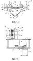
- Conveying apparatus 50 has conveying path 2 to convey postal matters P in the arrow direction T as shown in FIG. 14.
- two drive rollers 4 1 and 4 2 are provided along the conveying direction T apart each other.
- two driven rollers 6 1 and 6 2 are provided at the positions opposing to two drive rollers 4 1 and 4 2 at the other side of conveying path 2 at the upper side in FIG. 14. These two driven rollers 6 1 and 6 2 are driven in contact with drive rollers 4 1 and 4 2 , respectively.
- Roller portions of two driven rollers 6 1 and 6 2 described later are formed with elastic deformable material and deformed in contact with roller portions (described later) of corresponding drive rollers 4 1 and 4 2 .
- conveying path 2 is extending through nip 5 1 between drive roller 4 1 and driven roller 6 1 and nip 5 2 between drive roller 4 2 and driven roller 6 2 .
- two drive rollers 4 1 and 4 2 are in the same structure and two driven rollers 6 1 and 6 2 are in the same structure. Therefore, one of the will be explained below as a representing sample.
- Drive roller 4 1 (explained as a representative roller) has a rotational shaft 4a extending in the almost vertical direction and two roller portions 4 1 b and 4 1 c as shown in FIG. 15. Two roller portions 4 1 b and 4 1 c are fixed to rotational shaft 4a by separating to the upper and lower sides along rotational shaft 4a.
- the base portion of rotational shaft 4a is rotatably fixed to frame 1a of conveying apparatus 50. That is, housing 24 with plural bearings (not shown) incorporated is fixed to frame 1a and rotational shaft 4a is extending by passing through this housing 24.
- a pulley 4b is attached to the base portion of rotational shaft 4a projecting from housing 24, a pulley 4b is attached.
- Endless timing belt 11 is wound round pulley 4b and stretched between pulley 4b and pulley 12 attached to the rotational shaft of motor 13 fixed to frame 1a.
- This timing belt 11 is also wound round a pulley (not shown) attached to rotational shaft 4 2 a of other drive roller 4 2 . Then, when motor 13 is driven, two drive rollers 4 1 and 4 2 are rotated synchronously at a prescribed velocity in the arrow direction R shown in FIG. 14.
- driven roller 6 1 (explained as a representative sample) has rotational shaft 6a fixed to frame 1a. This rotational shaft 6a does not rotate against frame 1a.
- Rotational shaft 6a is provided with two rollers 6 1 b and 6 1 c formed with elastic deformable material apart in the axial direction and attached to rotational shaft 6a rotatable independently, respectively. That is, two roller portions 6 1 b and 6 1 c are attached to rotational shaft 6a via two bearings 7, respectively. Further, two roller portions 6 1 b and 6 1 c are positioned to contact two roller portions 4 1 b and 4 1 c of opposing drive roller 4 1 .
- the center distance between drive roller 4 1 and driven roller 6 1 is so set that roller portions 4 1 b, 6 1 b and 4 1 c, 6 1 c are press contacted. That is, rotational shafts 4a and 6a of two rollers 4 1 and 6 1 are attached to frame 1a at the fixed positions. Therefore, by elastically deforming the roller portions 6 1 b and 6 1 c of driven roller 6 1 , the thrusting force is produced between them. In addition, by elastically deforming roller portions 6 1 b and 6 1 c of driven roller 6 1 , postal matters P are allowed to pass between them.
- sensors 19a and 10b for detecting passage of postal matters P.
- Sensors 19a and 19b (hereinafter, collectively called sensor 19) has a light emission portion and a light receiving portion according to the positions at both sides of conveying path 2 and the optical axis extending between them at a position intersecting conveying path 2.
- Driven rollers 6 1 and 6 2 are in the same structure as those in the first embodiment and therefore, the explanation thereof will be omitted.
- the apparatus is in the two-layer structure and has driven rollers 6 1 and 6 2 provided in sponge 22 likewise the first embodiment. Further, hardness and thickness of sponge 22 become requisite conditions for obtaining deforming performance following postal matters P and adequate thrusting force by mutual interaction. When hardness is too hard or thickness is too thin, the following deformation may become difficult, defective conveying may result or drive roller 4 1 and 4 2 can be damaged. That is, in order for normally conveying postal matters P by the above-mentioned conveying apparatus 50, it is necessary to set coefficients of dynamic friction, hardness and thickness of driven rollers 6 1 and 6 2 at proper values.
- roller portions 6 1 b and 6 1 c of driven roller 6 1 are formed with elastically deformable material and the deforming amount is variable according to thickness of postal matter P passing through nip 5 1 between roller portions 4 1 b and 4 1 c of drive roller 4 1 .
- the deforming amount of roller portion 6 1 b to clamp and convey the thicker side of postal matter P is larger than roller portion 6 1 c to clamp and convey the thinner side.
- the apparent radius of roller portion 6 1 b becomes smaller than the apparent radius of roller portion 6 1 c in this case.
- the angular velocity of roller portion 6 1 b in small radius becomes larger than the angular velocity of roller portion 6 1 c in large radius. That is, the angular velocity of roller portion 6 1 b in small radius becomes larger because the running velocities of the outer surfaces of roller portions 61b and 61c to rotate in contact with postal matter P are the same.
- the running velocities of the outer surfaces that is, peripheral velocities of roller portions 6 1 b and 6 1 c become the same.
- roller portions 6 1 b and 6 1 c are fixed to rotational shaft 6a, angular velocities of rollers 6 1 b and 6 1 c become physically uniform and therefore, a difference is produced in peripheral velocities of two roller portions 6 1 b and 61 c in different radius.
- a difference is produced in the peripheral velocities of two roller portions 6 1 b and 6 1 c, a difference is produced in the conveying velocities to convey postal matters P, and not only postal matters P may be wrinkled but also may be torn in the worst case.
- roller portions 6 1 b and 6 1 c are attached to rotational shaft 6a rotatable independently in this embodiment.
- the angular velocities of roller portions 6 1 b and 6 1 c can be made different so as to cope with postal matters P in non-uniform thickness.
- two roller portions 6 1 b and 6 1 c provided to driven roller 6 1 coaxially are made rotatable independently from rotational shaft 6a. Therefore, even when postal matters P in non-uniform thickness are conveyed, the postal matters P can be conveyed steadily without causing wrinkle, skew, tear and other defects.
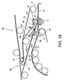
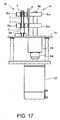
- FIG. 16 is a pan view showing the schematic structure of conveying direction switching apparatus 60 and FIG. 17 shows a side view of conveying direction switching apparatus 60 viewed from the direction to convey postal matters P (the arrow direction A in FIG. 16).
- the component members which function similarly to those of conveying apparatus 50 in the fourth embodiment described above will be assigned with the same reference numerals and the detailed explanation thereof will be omitted here.
- This conveying direction switching apparatus 60 is to detect positions of stamps pasted on postal matters P in advance and reverse the conveying directions of postal matters P based on the detected results in order to make the directions and two sides uniform.
- Conveying direction switching apparatus 60 has drive roller 4 1 and driven roller 6 1 that are rotated both in the forward and reverse directions by motor 13' (shown in FIG. 17).
- the rotational shaft of motor 13' is directly connected to rotational shaft 4a of drive roller 4 1 through a coupling 64.
- Rollers 4 1 and 6 1 are in the same structure as those in the fourth embodiment described above and fitted each other with pressure through conveying path 2.
- conveying direction switching apparatus 60 has a guide plate 61 extending along the lower surface side of conveying path 2 through a nip 5 3 between two rollers 4 1 and 6 1 .
- conveying direction switching apparatus 60 has a conveying belt 62 to send postal matters P in the arrow direction A in FIG. 17 toward nip 5 3 and a carry-out path 63 to send out postal matters P in the reverse direction from nip 53, that is, in the arrow direction B in FIG. 17. That is, conveying direction switching apparatus 60 is equipped with a conveying apparatus 65 which conveys postal matters P in the arrow direction A through conveying belt 62 and convey postal matters P in the arrow direction B through carry-out path 63. Conveying apparatus 65 has plural conveying rollers 66 and plural endless conveying belts 67 that are extended by wounding round these conveying rollers 66.
- a sensor 71 on conveying belt 62 to detect postal matters P passing through it likewise the fourth embodiment described above.
- This sensor 71 detects a length of a postal matter P along the conveying direction based on a time of postal matter P when its front end in the conveying direction passes the sensor till its rear end passes the sensor. That is, this sensor 71 is provided for obtaining deceleration, stopping and acceleration of drive roller 4 1 .
- sensors 72 and 73 are provided, respectively. These two sensors 72 and 73 detect presence of postal matters P in nip 5 3 .
- Conveying direction switching apparatus 60 described above operates as shown below.
- drive roller 4 1 is so controlled as to repeat the normal and reverse rotations according to a charging timing of postal matters P. Therefore, it becomes advantageous to construct the second layer of roller portions 6 2 b and 6 1 c of driven roller 61 with relatively light sponge 22 as in conveying direction switching apparatus 60 in this embodiment. That is, to reverse the conveying direction of postal matters P, it is necessary to reverse two rollers 4 1 and 6 1 in a moment and the moment of inertia of two rollers 4 1 and 6 1 in small will become advantageous.
- driven roller 6 1 when driven roller 6 1 is heavy, it becomes a large load when postal matters P are reversed and the reaction velocity at the time of reversing becomes slow.
- drive roller 6 1 in this embodiment becomes light in weight for the second layer constructed with sponge 22 and the moment of inertia can be made small.
- a load at the time of rotation can be reduced.
- the weight of driven roller 6 1 is in a range of 20 to 26 g including the weight of core metal 23 and when compared with driven roller 56 1 that is made a solid rubber roller, the weight could be suppressed to below 75% of it.
- roller portions 6 1 b and 6 1 c mounted along rotational shaft 6a of driven roller 6 1 are explained.
- more than 3 roller portions may be attached to one rotational shaft or one roller portion only can be attached.
- the rotational shaft may be attached rotatably to a frame.
- roller portions of driven roller 6 1 are attached rotatably independently, roller portions to be attached to different rotational shafts are not necessarily in the same diameter. Furthermore, the attaching positions of drive roller 4 1 and driven roller 6 1 are properly changeable.
- this invention applied to an apparatus to process postal matters P in different thickness is explained.
- this invention is applicable to apparatus for processing various forms including bankbooks, etc. in different thickness.
- materials and bonding agents used for the layers of driven rollers 6, 6 1 and 6 2 are not limited to those described in the above embodiments but are optionally changeable when the conditions described in the claims are satisfied.
- a paper-like material conveying apparatus, paper-like material conveying direction switching apparatus and paper-like material stamping apparatus of this invention are in the structures and have actions as described above and are capable of coping with paper-like materials in different thickness such as postal matters, bankbooks, etc. and displaying a good processing performance.
Landscapes
- Engineering & Computer Science (AREA)
- Mechanical Engineering (AREA)
- Delivering By Means Of Belts And Rollers (AREA)
Abstract
Description
Such results shown by P1 to P3 in FIG. 9 were obtained.
Claims (14)
- A paper-like material conveying apparatus comprising:wherein paper-like materials conveyed into the nip between the drive roller and the driven roller are pinched, conveyed and carried out.a drive roller which is given with a driving force, rotated and driven; anda driven roller arranged rotatably following the rotation of the drive rollers, the driven roller including a first layer formed with a solid elastic material that is in contact with the drive roller and a second layer formed with a foam elastic material that is formed at the inside from the first layer,
- A paper-like material conveying direction switching apparatus comprising:wherein paper-like materials in non-uniform thickness conveyed into the nip between the drive roller and the driven roller are pinched, conveyed and stopped and then, the drive roller is counter-rotated and the paper-like materials are carried out in the reverse direction.a drive roller which is given with a drive force, rotated and driven in both the forward and reverse directions; anda driven roller arranged rotatably following the rotation of the drive rollers, the driven roller including a first layer formed with a solid elastic material that is in contact with the drive roller and a second layer formed with a foam elastic material that is formed at the inside from the first layer,
- The apparatus according to claim 2 further comprising:a conveying apparatus to convey paper-like materials into the nip, receive paper-like materials carried out from the nip and convey in the counter-direction.
- A paper-like material stamping apparatus comprising:wherein a mark is stamped on the surfaces of paper-like materials in non-uniform thickness carried into the gap by contacting and rotating the cylindrical stamp thereon.a cylindrical stamp having a convex plate on the outer surface, which is given with a driving force and rotates;an ink supply portion to supply ink to the outer surface of the cylindrical stamp; anda platen roller arranged on the outer surface of the cylindrical stamp in the non-contact state via a prescribed gap, the platen roller including a first layer formed with a solid elastic material and a second layer formed with a foam elastic material that is formed at the inside from the first layer, and the platen roller being given with a driving force and rotated in the same direction as the cylindrical stamp,
- The apparatus according to claim 4, wherein the gap is smaller than the thickness of the thinnest paper-like material.
- A paper-like material conveying apparatus comprising:plural drive rollers to contact the same surfaces of paper-like materials taken out on a conveying path and rotate in the conveying direction at the same peripheral velocity; andplural driven rollers rigidly arranged in contact with plural drive rollers rotatably following the rotation of the drive rollers, respectively through the conveying path and allow to accept paper-like materials conveyed into nips between the driven rollers and the opposed drive rollers by elastically deforming and rotate independently each other.
- A paper-like material conveying direction switching apparatus comprising:wherein paper-like materials conveyed into the plural nips are conveyed while pinched and stopped and then, the plural drive rollers are counter-rotated and the paper-like materials are carried out in the reverse direction.plural drive rollers which contact the same surfaces of paper-like materials taken out on a conveying path and rotate in the same direction at the same peripheral velocity; andplural driven rollers which are arranged rigidly to contact the plural drive rollers through the conveying path, rotatably following the rotation of the drive rollers, allow to accept paper-like materials to the nips between the driven rollers and the opposed drive rollers by elastically deforming and rotate each other independently,
- The apparatus according to claim 6 or 7, further comprisinga frame to which rotational shafts of the plural drive rollers and rotational shafts of the plural driven rollers are attached rigidly.
- The apparatus according to one of claims 6 to 8, wherein the plural driven rollers have rotational shafts fixed to the frame rotatably independently to the rotational shafts.
- The apparatus according to one of claims 6 to 9, wherein the plural driven rollers are attached coaxially apart in the direction of the rotational shaft.
- The apparatus according to one of claims 6 to 10, wherein the plural drive rollers are attached coaxially apart in the direction of the rotational shaft.
- The apparatus according to one of claims 6 to 11, wherein the plural driven rollers are in the dual layers structure including a first layer formed with a solid elastic material and a second layer formed with a foam elastic material that is formed at the inside from the first layer.
- The apparatus according to one of claims 1 to 5 or 12, wherein thickness of the first layer is below 1/2 of that of the second layer, a coefficient of dynamic friction between the first layer and paper-like materials is more than 0.7 at less than a relative velocity difference 200 mm/s, a compression set of the second layer is below 5%, hardness of the second layer is below 40 at least at either Asker C hardness or JIS K 6253 E type hardness, and thickness of the second layer is more than 1.8 times of the most thick paper-like material.
- The apparatus according to one of claims 1 to 5, 12 or 13,
wherein tear strength of the second layer is more than 6 kN/m at JIS K 6252 (ISO 34-1, 34-2).
Applications Claiming Priority (6)
| Application Number | Priority Date | Filing Date | Title |
|---|---|---|---|
| JP2003047734 | 2003-02-25 | ||
| JP2003047734 | 2003-02-25 | ||
| JP2003315879 | 2003-09-08 | ||
| JP2003315879A JP2004277172A (en) | 2003-02-25 | 2003-09-08 | Sheet transport mechanism, sheet direction changing mechanism, and sheet stamping mechanism |
| JP2003355409 | 2003-10-15 | ||
| JP2003355409A JP4630532B2 (en) | 2003-10-15 | 2003-10-15 | Paper sheet direction change mechanism |
Publications (3)
| Publication Number | Publication Date |
|---|---|
| EP1452471A2 true EP1452471A2 (en) | 2004-09-01 |
| EP1452471A3 EP1452471A3 (en) | 2004-10-20 |
| EP1452471B1 EP1452471B1 (en) | 2006-05-17 |
Family
ID=32776822
Family Applications (1)
| Application Number | Title | Priority Date | Filing Date |
|---|---|---|---|
| EP03030009A Expired - Lifetime EP1452471B1 (en) | 2003-02-25 | 2003-12-30 | Paper-like material conveying apparatus |
Country Status (4)
| Country | Link |
|---|---|
| US (1) | US20040163558A1 (en) |
| EP (1) | EP1452471B1 (en) |
| KR (1) | KR100541493B1 (en) |
| DE (1) | DE60305292T8 (en) |
Cited By (1)
| Publication number | Priority date | Publication date | Assignee | Title |
|---|---|---|---|---|
| EP1947044A1 (en) * | 2007-01-18 | 2008-07-23 | Reifenhäuser GmbH & Co. KG Maschinenfabrik | Contact roller for a coiling machine |
Families Citing this family (7)
| Publication number | Priority date | Publication date | Assignee | Title |
|---|---|---|---|---|
| JP4256251B2 (en) * | 2003-12-17 | 2009-04-22 | 株式会社東芝 | Paper sheet direction reversing device and paper sheet stamping device |
| JP4698993B2 (en) * | 2004-09-15 | 2011-06-08 | 日立オムロンターミナルソリューションズ株式会社 | Thickness detector |
| KR101420591B1 (en) | 2010-11-05 | 2014-07-17 | 한국전자통신연구원 | Method of automatic marking based on compress roller and pin-press and apparatus for the same |
| JP6324212B2 (en) | 2014-05-27 | 2018-05-16 | サトーホールディングス株式会社 | Elastic roller |
| CN107043029A (en) * | 2016-02-09 | 2017-08-15 | 松下知识产权经营株式会社 | Roller, roller unit, paper feed and the reading device with paper feed |
| KR102133512B1 (en) * | 2019-03-11 | 2020-07-13 | 코세스지티 주식회사 | A curved glass printing apparatus provided with a transfer roller having a multi-layer structure and a printing method using the same |
| CN115043235B (en) * | 2022-07-25 | 2023-10-03 | 江苏长江纸业有限公司 | Reinforcing stamping device for binding back strip of book arranged on production line of book |
Family Cites Families (8)
| Publication number | Priority date | Publication date | Assignee | Title |
|---|---|---|---|---|
| DE2104166B1 (en) * | 1971-01-29 | 1972-08-24 | Mathias Baeurle Gmbh | |
| US4167612A (en) * | 1978-06-19 | 1979-09-11 | Wm. T. Burnett & Co., Inc. | Flexible polyurethane foams having low resistance to air flow and method for preparation |
| JPS58104863A (en) * | 1981-12-16 | 1983-06-22 | Fuji Xerox Co Ltd | Paper feed device |
| JPS6061443A (en) * | 1983-09-13 | 1985-04-09 | Fuji Xerox Co Ltd | Roller for document conveyor |
| US4974680A (en) * | 1988-11-14 | 1990-12-04 | Tokyo Electric Co., Ltd. | Sheet-feeding mechanism |
| JP3380061B2 (en) * | 1994-09-19 | 2003-02-24 | 富士ゼロックス株式会社 | Paper feed roll, method for producing the same, and silicone rubber composition for paper feed roll |
| JP3258832B2 (en) * | 1994-09-30 | 2002-02-18 | キヤノン株式会社 | Sheet material supply device and image forming device |
| JP3072055B2 (en) * | 1996-07-23 | 2000-07-31 | 株式会社荒井製作所 | Pressure roller |
-
2003
- 2003-12-30 EP EP03030009A patent/EP1452471B1/en not_active Expired - Lifetime
- 2003-12-30 DE DE60305292T patent/DE60305292T8/en active Active
- 2003-12-30 KR KR1020030099620A patent/KR100541493B1/en not_active Expired - Fee Related
-
2004
- 2004-02-18 US US10/779,768 patent/US20040163558A1/en not_active Abandoned
Cited By (1)
| Publication number | Priority date | Publication date | Assignee | Title |
|---|---|---|---|---|
| EP1947044A1 (en) * | 2007-01-18 | 2008-07-23 | Reifenhäuser GmbH & Co. KG Maschinenfabrik | Contact roller for a coiling machine |
Also Published As
| Publication number | Publication date |
|---|---|
| DE60305292D1 (en) | 2006-06-22 |
| KR20040076574A (en) | 2004-09-01 |
| DE60305292T8 (en) | 2007-08-02 |
| US20040163558A1 (en) | 2004-08-26 |
| KR100541493B1 (en) | 2006-01-11 |
| EP1452471A3 (en) | 2004-10-20 |
| DE60305292T2 (en) | 2007-04-26 |
| EP1452471B1 (en) | 2006-05-17 |
Similar Documents
| Publication | Publication Date | Title |
|---|---|---|
| EP1452471B1 (en) | Paper-like material conveying apparatus | |
| KR100701323B1 (en) | Paper feeder of image forming apparatus | |
| JP4537213B2 (en) | Sheet feeding device | |
| JP2010037047A (en) | Sheet material feeder and image forming device using the same | |
| JP6242996B2 (en) | Paper sheet processing equipment | |
| US10538411B2 (en) | Sheet conveying device | |
| US20070267807A1 (en) | Sheet processing apparatus and sheet processing method | |
| EP0514441B1 (en) | A method of, and apparatus for, delivering flat articles one by one from a stack of such articles | |
| EP1918231A2 (en) | Singulation module/belt for separating sheet material | |
| KR101290607B1 (en) | Bill transport apparatus | |
| EP1529747B1 (en) | Sheets processing apparatus | |
| US6227375B1 (en) | Device for monitoring the transport process of flat despatches | |
| CN1822053A (en) | Discrimination apparatus and roller assembly | |
| US7753359B2 (en) | Sheet conveyance apparatus and image forming apparatus | |
| JP2004277172A (en) | Sheet transport mechanism, sheet direction changing mechanism, and sheet stamping mechanism | |
| US20120001379A1 (en) | Sheet separation mechanism and image forming apparatus | |
| US6782237B2 (en) | Shape-correcting device for sheets and electrophotographic device | |
| US20260035192A1 (en) | Paper feeding roll | |
| JP2004299842A (en) | Paper feed roller for double feed prevention mechanism of paper feeder | |
| JP3957980B2 (en) | Sheet material conveying device and image forming device | |
| JP2004338854A (en) | Paper stamping device | |
| JP4226751B2 (en) | Paper sheet processing equipment | |
| JP4630532B2 (en) | Paper sheet direction change mechanism | |
| JP3888825B2 (en) | Paper feeder | |
| JP2008179467A (en) | Device for separating and supplying sample sheet and method of separating and supplying sample sheet |
Legal Events
| Date | Code | Title | Description |
|---|---|---|---|
| PUAI | Public reference made under article 153(3) epc to a published international application that has entered the european phase |
Free format text: ORIGINAL CODE: 0009012 |
|
| 17P | Request for examination filed |
Effective date: 20031230 |
|
| AK | Designated contracting states |
Kind code of ref document: A2 Designated state(s): AT BE BG CH CY CZ DE DK EE ES FI FR GB GR HU IE IT LI LU MC NL PT RO SE SI SK TR |
|
| AX | Request for extension of the european patent |
Extension state: AL LT LV MK |
|
| PUAL | Search report despatched |
Free format text: ORIGINAL CODE: 0009013 |
|
| AK | Designated contracting states |
Kind code of ref document: A3 Designated state(s): AT BE BG CH CY CZ DE DK EE ES FI FR GB GR HU IE IT LI LU MC NL PT RO SE SI SK TR |
|
| AX | Request for extension of the european patent |
Extension state: AL LT LV MK |
|
| AKX | Designation fees paid |
Designated state(s): DE FR GB IT SE |
|
| GRAP | Despatch of communication of intention to grant a patent |
Free format text: ORIGINAL CODE: EPIDOSNIGR1 |
|
| GRAS | Grant fee paid |
Free format text: ORIGINAL CODE: EPIDOSNIGR3 |
|
| GRAA | (expected) grant |
Free format text: ORIGINAL CODE: 0009210 |
|
| AK | Designated contracting states |
Kind code of ref document: B1 Designated state(s): DE FR GB IT SE |
|
| REG | Reference to a national code |
Ref country code: GB Ref legal event code: FG4D |
|
| REF | Corresponds to: |
Ref document number: 60305292 Country of ref document: DE Date of ref document: 20060622 Kind code of ref document: P |
|
| REG | Reference to a national code |
Ref country code: SE Ref legal event code: TRGR |
|
| PGFP | Annual fee paid to national office [announced via postgrant information from national office to epo] |
Ref country code: SE Payment date: 20061206 Year of fee payment: 4 |
|
| ET | Fr: translation filed | ||
| PLBE | No opposition filed within time limit |
Free format text: ORIGINAL CODE: 0009261 |
|
| STAA | Information on the status of an ep patent application or granted ep patent |
Free format text: STATUS: NO OPPOSITION FILED WITHIN TIME LIMIT |
|
| 26N | No opposition filed |
Effective date: 20070220 |
|
| EUG | Se: european patent has lapsed | ||
| GBPC | Gb: european patent ceased through non-payment of renewal fee |
Effective date: 20071230 |
|
| PG25 | Lapsed in a contracting state [announced via postgrant information from national office to epo] |
Ref country code: SE Free format text: LAPSE BECAUSE OF NON-PAYMENT OF DUE FEES Effective date: 20071231 |
|
| PG25 | Lapsed in a contracting state [announced via postgrant information from national office to epo] |
Ref country code: GB Free format text: LAPSE BECAUSE OF NON-PAYMENT OF DUE FEES Effective date: 20071230 |
|
| PGFP | Annual fee paid to national office [announced via postgrant information from national office to epo] |
Ref country code: IT Payment date: 20121218 Year of fee payment: 10 |
|
| PG25 | Lapsed in a contracting state [announced via postgrant information from national office to epo] |
Ref country code: IT Free format text: LAPSE BECAUSE OF NON-PAYMENT OF DUE FEES Effective date: 20131231 |
|
| REG | Reference to a national code |
Ref country code: FR Ref legal event code: PLFP Year of fee payment: 13 |
|
| PG25 | Lapsed in a contracting state [announced via postgrant information from national office to epo] |
Ref country code: IT Free format text: LAPSE BECAUSE OF NON-PAYMENT OF DUE FEES Effective date: 20131230 |
|
| REG | Reference to a national code |
Ref country code: FR Ref legal event code: PLFP Year of fee payment: 14 |
|
| REG | Reference to a national code |
Ref country code: FR Ref legal event code: PLFP Year of fee payment: 15 |
|
| PGFP | Annual fee paid to national office [announced via postgrant information from national office to epo] |
Ref country code: DE Payment date: 20211102 Year of fee payment: 19 |
|
| PGFP | Annual fee paid to national office [announced via postgrant information from national office to epo] |
Ref country code: FR Payment date: 20221110 Year of fee payment: 20 |
|
| REG | Reference to a national code |
Ref country code: DE Ref legal event code: R119 Ref document number: 60305292 Country of ref document: DE |
|
| PG25 | Lapsed in a contracting state [announced via postgrant information from national office to epo] |
Ref country code: DE Free format text: LAPSE BECAUSE OF NON-PAYMENT OF DUE FEES Effective date: 20230701 |