EP1452445B1 - Stretch film wrapping machine - Google Patents
Stretch film wrapping machine Download PDFInfo
- Publication number
- EP1452445B1 EP1452445B1 EP04250790A EP04250790A EP1452445B1 EP 1452445 B1 EP1452445 B1 EP 1452445B1 EP 04250790 A EP04250790 A EP 04250790A EP 04250790 A EP04250790 A EP 04250790A EP 1452445 B1 EP1452445 B1 EP 1452445B1
- Authority
- EP
- European Patent Office
- Prior art keywords
- wrapping machine
- frame
- lifting
- lifting frame
- drive belt
- Prior art date
- Legal status (The legal status is an assumption and is not a legal conclusion. Google has not performed a legal analysis and makes no representation as to the accuracy of the status listed.)
- Expired - Lifetime
Links
- 229920006302 stretch film Polymers 0.000 title 1
- 239000011888 foil Substances 0.000 claims abstract description 33
- 230000005540 biological transmission Effects 0.000 claims abstract description 20
- 230000033001 locomotion Effects 0.000 claims abstract description 10
- 238000012423 maintenance Methods 0.000 description 6
- 238000010276 construction Methods 0.000 description 4
- 230000005611 electricity Effects 0.000 description 3
- 239000000314 lubricant Substances 0.000 description 2
- 230000000712 assembly Effects 0.000 description 1
- 238000000429 assembly Methods 0.000 description 1
- 238000009434 installation Methods 0.000 description 1
Images

Classifications
-
- B—PERFORMING OPERATIONS; TRANSPORTING
- B65—CONVEYING; PACKING; STORING; HANDLING THIN OR FILAMENTARY MATERIAL
- B65B—MACHINES, APPARATUS OR DEVICES FOR, OR METHODS OF, PACKAGING ARTICLES OR MATERIALS; UNPACKING
- B65B11/00—Wrapping, e.g. partially or wholly enclosing, articles or quantities of material, in strips, sheets or blanks, of flexible material
- B65B11/06—Wrapping articles, or quantities of material, by conveying wrapper and contents in common defined paths
-
- B—PERFORMING OPERATIONS; TRANSPORTING
- B65—CONVEYING; PACKING; STORING; HANDLING THIN OR FILAMENTARY MATERIAL
- B65B—MACHINES, APPARATUS OR DEVICES FOR, OR METHODS OF, PACKAGING ARTICLES OR MATERIALS; UNPACKING
- B65B11/00—Wrapping, e.g. partially or wholly enclosing, articles or quantities of material, in strips, sheets or blanks, of flexible material
- B65B11/02—Wrapping articles or quantities of material, without changing their position during the wrapping operation, e.g. in moulds with hinged folders
- B65B11/025—Wrapping articles or quantities of material, without changing their position during the wrapping operation, e.g. in moulds with hinged folders by webs revolving around stationary articles
-
- B—PERFORMING OPERATIONS; TRANSPORTING
- B65—CONVEYING; PACKING; STORING; HANDLING THIN OR FILAMENTARY MATERIAL
- B65B—MACHINES, APPARATUS OR DEVICES FOR, OR METHODS OF, PACKAGING ARTICLES OR MATERIALS; UNPACKING
- B65B11/00—Wrapping, e.g. partially or wholly enclosing, articles or quantities of material, in strips, sheets or blanks, of flexible material
- B65B11/58—Applying two or more wrappers, e.g. in succession
- B65B11/585—Applying two or more wrappers, e.g. in succession to stacked articles, e.g. pallettised loads
-
- B—PERFORMING OPERATIONS; TRANSPORTING
- B65—CONVEYING; PACKING; STORING; HANDLING THIN OR FILAMENTARY MATERIAL
- B65B—MACHINES, APPARATUS OR DEVICES FOR, OR METHODS OF, PACKAGING ARTICLES OR MATERIALS; UNPACKING
- B65B2210/00—Specific aspects of the packaging machine
- B65B2210/14—Details of wrapping machines with web dispensers for application of a continuous web in layers onto the articles
- B65B2210/16—Details of wrapping machines with web dispensers for application of a continuous web in layers onto the articles the web dispenser travelling around the article along a non-rotating ring
-
- B—PERFORMING OPERATIONS; TRANSPORTING
- B65—CONVEYING; PACKING; STORING; HANDLING THIN OR FILAMENTARY MATERIAL
- B65B—MACHINES, APPARATUS OR DEVICES FOR, OR METHODS OF, PACKAGING ARTICLES OR MATERIALS; UNPACKING
- B65B2210/00—Specific aspects of the packaging machine
- B65B2210/14—Details of wrapping machines with web dispensers for application of a continuous web in layers onto the articles
- B65B2210/18—Details of wrapping machines with web dispensers for application of a continuous web in layers onto the articles the web dispenser being mounted on a rotary ring
Definitions
- the wrapping machine comprises a circular ring arrangement, which forms the path of motion of the foil dispenser and which is mounted on the lifting frame so as to be vertically movable with it.
Abstract
Description
- In prior art, a wrapping machine used to wrap a plastic foil web around an object to be wrapped is known.
- In particular
EP-A-0 811 554 discloses a machine according to the preamble of claim 1. - Wrapping machines are known e.g. from the documents
EP-A-0 811 554 ,EP-A-0 336 517 andUS-A-5 450 709 . - The object to be wrapped is usually a load placed on a pallet, which typically is an assembly of the form of a rectangular parallelepiped. The wrapping machine comprises a machine frame supported on a fixed floor base. The frame usually comprises four upright vertical columns. The wrapping machine further comprises a lifting frame arranged to be vertically movable upwards and downwards, being guided by the vertical columns. Further, the wrapping machine comprises a lifting motor for moving the lifting frame, and power transmission means for the transmission of power from the lifting motor to produce vertical motion of the lifting frame. The power transmission means comprise elongate flexible drive elements and wheels for the transmission of the power of the lifting motor to the drive elements.
- The wrapping machine further comprises a foil dispenser, on which a foil web roll can be rotatably supported. Supported by the lifting frame is a wrapping frame, which usually forms a circular endless path for the foil dispenser. The foil dispenser circulates along this path around the object to be packaged, allowing the plastic foil web to be unrolled from the foil web roll to form a wrapping around the object to be packaged.
- This type of prior-art wrapping machine has a so-called top frame fixed to the upper ends of the vertical columns and consisting of beams connecting the upper ends of the vertical columns. The lifting motor is connected to this top frame. The aforesaid elongate drive elements of the power transmission means transmitting the power of the lifting motor to produce a vertical motion of the lifting frame are power transmission chains and the wheels are chain sprockets. Mounted at the upper and lower ends of each vertical column are diverting sprockets, over which the vertically moving endless chain runs. The lifting frame is fixed to these vertical chains. A diverting sprocket on one of the vertical columns is driven by the lifting motor. From this single lifting motor, power is correspondingly transmitted to the other side of the machine by chains via diverting and tensioning sprockets rotatably mounted on the top frame. The diverting sprockets at the upper ends of opposite vertical columns are connected to each other by shafts. With this arrangement, the lifting frame fixed to the chains at four points is raised and lowered evenly by means of a single lifting motor.
- A problem with the prior-art wrapping machine is that the task of assembling it is difficult to carry out. Numerous parts have to be mounted on the top frame at a relatively large height from the floor level, which, besides being difficult, is also problematic in respect of work safety. The prior-art wrapping machine contains various parts requiring regular maintenance that are located at a large height. For example, the bearings of the shafts and sprockets have to be repeatedly lubricated, which is why it is necessary to provide special lubricant pipes for passing a lubricant to the objects to be lubricated. Further, the mechanism needed for moving the lifting frame in the prior-art wrapping machine comprises a very large number of components, resulting in a complicated and expensive construction. Moreover, as the lifting motor, which usually is an electric motor, is mounted on the top frame, very long cables are needed for electricity supply and control.
- According to the invention, the lifting motor of the lifting frame of the wrapping machine is secured to the lifting frame so as to be movable with it. The wheels of the power transmission means comprise a drive belt pulley fitted for reeling a belt, said drive belt pulley being rotatably mounted by means of a bearing on the lifting frame and rotated by the lifting motor. Each one of the elongate drive elements consists of a drive belt whose first end is secured to the upper end of the vertical columns while the second end is secured to the drive belt pulley. Thus, when the drive belt pulley is rotated by the lifting motor, the drive belt is reeled around it, thereby moving the lifting frame.
- As the lifting motor is placed on the lifting frame and the motion is implemented using belts and pulleys, an assembly-friendly wrapping machine construction is achieved because the apparatus can be assembled without working at a level high up above the floor. The lifting frame together with the motor forms a unitary subassembly, which can be assembled in an ergonomic manner e.g. on the top of a work table. Likewise, all the essential maintenance objects are located in the lifting frame, which can be adjusted to a suitable height for maintenance. The motor control and electricity cables can be made short. The construction of the wrapping machine is simple and it contains only few components.
- In an embodiment of the wrapping machine, the wrapping machine comprises four vertical columns, arranged in a rectangular configuration at the corners of a rectangle at a distance from each other. The lifting frame has the form of a substantially rectangular frame and is arranged in a horizontal orientation within the area defined by the vertical columns.
- In an embodiment of the wrapping machine, the lifting frame comprises an equipment box, whose interior space is defined below by a bottom, laterally by side walls and above by a cover. The lifting motor is mounted in this interior space. In an embodiment of the wrapping machine, the lifting frame comprises two parallel elongate lateral frame parts, each extending horizontally between two vertical columns. The drive belt pulley is mounted in a position aligned with a lateral frame part and a diverting pulley is provided at each end of the two lateral frame parts, the drive belt coming from the drive belt pulley being passed over said diverting pulleys to the upper end of the vertical column.
- In an embodiment of the wrapping machine, the power transmission means comprise a drive shaft to which the lifting motor is coupled to rotate it. A drive belt pulley is mounted at each end of the drive shaft.
- In an embodiment of the wrapping machine, the wrapping machine comprises a circular ring arrangement, which forms the path of motion of the foil dispenser and which is mounted on the lifting frame so as to be vertically movable with it.
- In an embodiment of the wrapping machine, the circular ring arrangement comprises a ring-like rotary frame suspended horizontally so that it is supported by the lifting frame and mounted on bearings on the lifting frame so as to be rotatable about its center, the foil dispenser being secured to said rotary frame to circulate with it, and a rotating motor for rotating the rotary frame.
- In an embodiment of the wrapping machine, the rotating motor is placed in the interior space of the equipment box. Placing the rotating motor in the same box with the lifting motor further facilitates assembly and maintenance.
- In an embodiment of the wrapping machine, the wrapping machine comprises a control device for controlling the operation of the wrapping machine, such as the operation of the lifting motor and/or the rotating motor. The control device is placed in the interior space of the equipment box, so the control device is as close as possible to the motors to be controlled and the cables are short.
- An advantage of the invention is that the wrapping machine is simpler in construction than earlier machines and contains as few components as possible. Another advantage is that it contains no installation or maintenance objects located high up above the floor level. Thus, assembly and maintenance can be carried out while the person performing the work is working at the floor level without having to climb high up to perform the work.
- Further, cabling required for electricity and control can be made short. In the following, the invention will be described in detail by the aid of an embodiment example with reference to the attached drawing, wherein
-
Fig. 1 presents an axonometric oblique top view of an embodiment of the wrapping machine of the invention, with the lifting frame and the vertical columns depicted as being transparent to visualize the drive arrangement of the lifting frame, -
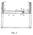
Fig. 2 presents a diagrammatic sectional view along line II-II inFig. 1 to illustrate the lifting frame drive arrangement, and -
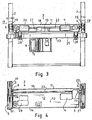
Fig. 3 presents a sectional view along line III-III inFig. 1 , and -
Fig. 4 presents a sectional view along line IV-IV inFig. 3 . -
Fig. 1 presents a wrapping machine for wrapping a plastic foil web around an object (not shown) to be packaged. The wrapping machine comprises a machine frame 1 supported on a fixed floor base. The machine frame 1 comprises four uprightvertical columns 2 arranged at a distance from each other in a rectangular configuration such that avertical column 2 is placed at each corner of the imaginary rectangular configuration. A liftingframe 3 has been arranged to be vertically movable along thevertical columns 2 by means of a liftingmotor 4. Power is transmitted by power transmission means from the liftingmotor 4 to produce a vertical motion of thelifting frame 3. The power transmission means comprise flexibleflat belts 5 andpulleys 6 for transmitting the power of the liftingmotor 4 to theflat belts 5. Afoil dispenser 7, on which afoil web roll 8 can be rotatably mounted, has been arranged to circulate on a ring-like circular path around the object to be packaged, in such manner that the plastic foil web is unrolled from thefoil web roll 8, forming a wrapping around the object to be packaged, and as the frame arrangement supporting the foil dispenser is simultaneously moved vertically by moving the lifting frame, a spiral wrapping is formed around the object to be wrapped. - It is to be noted that the circulating movement of the
foil dispenser 7 along a ring-like path can be achieved by other known arrangements as well, such as arrangements in which the foil dispenser is connected to a rotating crank that circulates thefoil dispenser 7 about the object to be wrapped. - The lifting
motor 4 is secured to thelifting frame 3 and it therefore moves with thelifting frame 3. As is also shown inFig. 2 , adrive belt pulley 6 for reeling theflat belts 5 is provided. Thedrive belt pulley 6 is rotatably mounted by means of a bearing on thelifting frame 3 and connected to the shaft of the liftingmotor 4. The first ends 9 of theflat belts 5 are secured to the upper ends of thevertical columns 2 while their second ends 10 are secured to thedrive belt pulley 6. - The
lifting frame 3 has the shape of a substantially rectangular frame and it is disposed in a horizontal position within the area defined by thevertical columns 2. As can be best seen fromfigures 1 ,3 and 4 , thelifting frame 3 is provided with anequipment box 11, theinterior space 12 of which is defined below by a bottom 13, laterally byside walls cover 18. The liftingmotor 4 is disposed in theinterior space 12 of theequipment box 11. From allfigures 1 - 4 it can be seen that thelifting frame 3 comprises two elongate box-likelateral frame parts vertical columns 2. Thedrive belt pulley 6 is mounted inside the box of a lateral frame part. As shown inFig. 1 and2 , a divertingpulley 21 is provided at each end of the twolateral frame parts drive belt 5 coming from thedrive belt pulley 6 is passed to the upper end of thevertical column 2. - As shown in
Fig. 3 and 4 , the power transmission means further comprise adrive shaft 22 rotated by the liftingmotor 4, which is connected to it via a reduction gear. Mounted on each end of thedrive shaft 22 is adrive belt pulley 6. - Referring to
Fig. 1 and3 , the apparatus comprises acircular ring arrangement 23 forming the path of movement of thefoil dispenser 7. Thecircular ring arrangement 23 is suspended on thelifting frame 3 so as to be vertically movable with it. Thecircular ring arrangement 23 comprises a circular ring-likerotary frame 25 suspended in a horizontal position on thelifting frame 3 and mounted by means ofroller assemblies 28 allowing it to rotate about its center. Thefoil dispenser 7 is secured to therotary frame 25 so that it circulates with the rotary frame. To rotate therotary frame 25, arotating motor 26 is provided. Therotating motor 26 is placed in theinterior space 12 of theequipment box 11. Acontroller 27 arranged to control the functions of the wrapping machine, such as the liftingmotor 4 and therotating motor 26, is likewise placed in theinterior space 12 of theequipment box 11.
Claims (9)
- Wrapping machine for wrapping a plastic foil web around an object to be packaged, said wrapping machine comprising- a machine frame (1) supported on a fixed base and comprising upright vertical columns (2),- a lifting frame (3) arranged to be vertically movable upwards and downwards and guided by the vertical columns (2),- a lifting motor (4) for moving the lifting frame,- power transmission means for the transmission of power from the lifting motor to produce vertical motion of the lifting frame, said power transmission means comprising elongate flexible drive elements (5) and wheels for the transmission of the power of the lifting motor to the drive elements,- a foil dispenser (7), on which a foil web roll (8) can be rotatably mounted, said foil dispenser being arranged to circulate on a ring-like path about the object to be packaged for delivering a plastic foil web from the foil web roll to form a wrapping around the object to be packaged,characterized in that the lifting motor (4) is secured to the lifting frame (3) so as to be movable with it;
that the wheels comprise a drive belt pulley (6) fitted for reeling a flat belt, said drive belt pulley (6) being rotatably mounted on bearings on the lifting frame (3) and rotated by the lifting motor (4); and
that each one of the elongate drive elements (5) consists of a drive belt whose first end (9) is secured to the upper end of the vertical columns while the second end (10) is secured to the drive belt pulley (6). - Wrapping machine according to claim 1, characterized in that the wrapping machine comprises four vertical columns (2), arranged in a rectangular configuration at the corners of a rectangle at a distance from each other; and that the lifting frame (3) has the form of a substantially rectangular frame and arranged in a horizontal orientation within the area defined by the vertical columns (2).
- Wrapping machine according to claim 1 or 2, characterized in that the lifting frame (3) comprises an equipment box (11), whose interior space (12) is defined below by a bottom (13), laterally by side walls (14, 15, 16, 117) and above by a cover (18), and that the lifting motor (4) is mounted in said interior space (12).
- Wrapping machine according to any one of claims 1 - 3, characterized in that the lifting frame (3) comprises two parallel elongate lateral frame parts (19, 20), each extending horizontally between two vertical columns (2); and that the drive belt pulley (6) is mounted in a position aligned with a lateral frame part and a diverting pulley (21) is provided at each end of the two lateral frame parts (19, 20), the drive belt (5) coming from the drive belt pulley (6) being passed over the respective diverting pulley to the upper end of the vertical column (2).
- Wrapping machine according to any one of claims 1 - 4, characterized in that the power transmission means comprise a drive shaft (22) to which the lifting motor (4) is coupled to rotate it, a drive belt pulley (6) being mounted on each end of said drive shaft (22).
- Wrapping machine according to any one of claims 1 - 5, characterized in that the wrapping machine comprises a circular ring arrangement (23), which forms the path of motion of the foil dispenser (7) and which is so mounted on the lifting frame (3) as to be vertically movable with it.
- Wrapping machine according to claim 6, characterized in that the circular ring arrangement (23) comprises- a ring-like rotary frame (25) suspended horizontally so that it is carried by the lifting frame (3) and mounted on bearings on the lifting frame to allow it to rotate about its center, the foil dispenser (7) being secured to said rotary frame (25) to circulate with it, and- a rotating motor (26) for rotating the rotary frame (25).
- Wrapping machine according to claim 7, characterized in that the rotating motor (26) is placed in the interior space (12) of the equipment box (11).
- Wrapping machine according to claim 7 or 8, characterized in that the wrapping machine comprises a control device (27) for controlling the operation of the wrapping machine, such as the lifting motor (4) and/or the rotating motor (26), and that the control device (27) is placed in the interior space (12) of the equipment box (11).
Applications Claiming Priority (2)
| Application Number | Priority Date | Filing Date | Title |
|---|---|---|---|
| FI20030304 | 2003-02-27 | ||
| FI20030304A FI115623B (en) | 2003-02-27 | 2003-02-27 | Wrapping machine and wrapper |
Publications (2)
| Publication Number | Publication Date |
|---|---|
| EP1452445A1 EP1452445A1 (en) | 2004-09-01 |
| EP1452445B1 true EP1452445B1 (en) | 2009-09-16 |
Family
ID=8565737
Family Applications (1)
| Application Number | Title | Priority Date | Filing Date |
|---|---|---|---|
| EP04250790A Expired - Lifetime EP1452445B1 (en) | 2003-02-27 | 2004-02-13 | Stretch film wrapping machine |
Country Status (15)
| Country | Link |
|---|---|
| US (1) | US6945018B2 (en) |
| EP (1) | EP1452445B1 (en) |
| JP (1) | JP2004256175A (en) |
| KR (1) | KR101095379B1 (en) |
| CN (1) | CN1289353C (en) |
| AT (1) | ATE442989T1 (en) |
| AU (1) | AU2004200800B2 (en) |
| BR (1) | BRPI0400548B1 (en) |
| CA (1) | CA2459124C (en) |
| DE (1) | DE602004023146D1 (en) |
| ES (1) | ES2333717T3 (en) |
| FI (1) | FI115623B (en) |
| MX (1) | MXPA04001947A (en) |
| NZ (1) | NZ531285A (en) |
| TW (1) | TWI265900B (en) |
Cited By (1)
| Publication number | Priority date | Publication date | Assignee | Title |
|---|---|---|---|---|
| CN101137543B (en) * | 2005-02-10 | 2010-08-25 | 奥伊M.赫洛伊拉私人公司 | Method and device for forming a top film sheet from a film web |
Families Citing this family (19)
| Publication number | Priority date | Publication date | Assignee | Title |
|---|---|---|---|---|
| ES2301314B1 (en) * | 2005-11-23 | 2009-05-01 | Diseños Integrales Del Embalaje, S.A. | HIGH SPEED WINDER. |
| EP1816074B1 (en) * | 2006-02-07 | 2008-09-10 | Mecwrap S.r.l. | Improved packaging machine, for packaging products by wrapping them with a continuous web of packaging film |
| US7731082B2 (en) * | 2006-05-08 | 2010-06-08 | Packaging Corporation Of America | Continuously wound reinforced container and method of making the same |
| US20080229714A1 (en) * | 2007-03-19 | 2008-09-25 | Illinois Tool Works Inc. | Film wrapping machine utilizing two film carriage assemblies to effectively perform film change operations |
| US20080229716A1 (en) * | 2007-03-19 | 2008-09-25 | Illinois Tool Works Inc. | Film wrapping machine simultaneously utilizing two film carriage assemblies |
| US8448843B2 (en) * | 2008-07-08 | 2013-05-28 | Packaging Corporation Of America | Two-piece container assembly and methods of making the same |
| US8919636B2 (en) | 2008-07-08 | 2014-12-30 | Packaging Corporation Of America | Coated two-piece container assembly and methods of making the same |
| KR101604752B1 (en) | 2009-08-06 | 2016-03-18 | 엘지전자 주식회사 | Robot refrigerator and system including the same |
| CN102583048B (en) * | 2012-02-23 | 2014-06-18 | 浙江星星家电股份有限公司 | Suitcase shifting device |
| CN103879579B (en) * | 2014-01-15 | 2018-02-02 | 元旭包装(上海)有限公司 | One kind winding film mulching integrated machine |
| CN104925309A (en) * | 2015-06-03 | 2015-09-23 | 长兴金润大正机械有限公司 | Film hanging device of battery pack film coating machine |
| CN104909003A (en) * | 2015-06-03 | 2015-09-16 | 长兴金润大正机械有限公司 | Thin film conveying mechanism |
| IT201800002669A1 (en) * | 2018-02-14 | 2019-08-14 | Aetna Group Spa | WRAPPING MACHINE |
| US11352152B2 (en) | 2019-09-20 | 2022-06-07 | Signode Industrial Group Llc | Stretch-wrapping machine with self-adjusting pinch rollers |
| US11447057B2 (en) * | 2019-11-25 | 2022-09-20 | Norco Industries, Inc. | Floor positioning system |
| CN111907760B (en) * | 2020-07-27 | 2022-02-15 | 东南大学 | Cable-stayed/sling surface winding device |
| CN112027154B (en) * | 2020-08-31 | 2021-10-29 | 山东滨州智源生物科技有限公司 | Packaging machine |
| KR102259203B1 (en) | 2021-04-28 | 2021-05-31 | 윤명구 | Wrapping robot with enhanced safety and reliability |
| CN116253184B (en) * | 2022-12-06 | 2023-10-17 | 宿迁市华力新材料科技有限公司 | Foil connecting device for corrosion foil production |
Family Cites Families (22)
| Publication number | Priority date | Publication date | Assignee | Title |
|---|---|---|---|---|
| US4109445A (en) * | 1977-07-26 | 1978-08-29 | Shulman Michael H | Overhead load-wrapping apparatus |
| US4369614A (en) * | 1980-11-17 | 1983-01-25 | Tetzner Siegfried K | Wrapping apparatus |
| SE454870C (en) * | 1981-11-03 | 1989-10-10 | Karl Johan Back | PROCEDURES FOR PACKAGING CYLINDRICAL GOODS |
| US4587796B1 (en) * | 1983-04-21 | 1997-12-23 | Newtec Int | Packaging machine |
| US4756143A (en) * | 1987-02-26 | 1988-07-12 | Lantech, Inc. | Lower guided lower driven wrapping device |
| FI80418C (en) * | 1988-04-06 | 1990-06-11 | Haloila M Oy Ab | ANORDINATION OF FOERFARANDE FOR EXAMINATION AV EN OMSLAGSFILM VID INVECKLING. |
| DE3820048A1 (en) * | 1988-06-13 | 1989-12-14 | Ggv Gustav Grolman Verpackungs | Process and apparatus for producing a packaging unit by winding a foil web round the material to be packaged |
| US5131209A (en) * | 1991-06-19 | 1992-07-21 | Appleton Papers Inc. | Vertical foam wrapping machine and method for wrapping a roll of carbonless paper |
| US5390476A (en) * | 1993-06-30 | 1995-02-21 | Newtec International | Apparatus for wrapping articles in plastic film |
| US5450709A (en) * | 1993-10-29 | 1995-09-19 | Sds, Inc. | Stationary pallet stretch wrapping device having improved method and apparatus for gripping and cutting or wrapping film |
| GB9502158D0 (en) * | 1995-02-03 | 1995-03-22 | Mancon Engineering Ltd | Apparatus for wrapping an object with a web of material |
| US5878555A (en) * | 1995-06-08 | 1999-03-09 | Newtec International S.A | Apparatus for wrapping articles in plastic film |
| JP3103759B2 (en) * | 1996-03-07 | 2000-10-30 | 第一技建株式会社 | Three-dimensional containment tower |
| US5768862A (en) * | 1996-05-06 | 1998-06-23 | Robopac Sistemi S.R.L. | Apparatus for the wrapping of palletized product groups with plastic film |
| JP3639733B2 (en) * | 1998-12-28 | 2005-04-20 | 新日本製鐵株式会社 | Mold short side changer for assembly molds |
| US6594970B1 (en) * | 1999-06-10 | 2003-07-22 | Quipp Systems, Inc. | Method and apparatus for wrapping palletized bundles |
| US6449928B1 (en) | 2000-11-27 | 2002-09-17 | Illinois Tool Works Inc. | Single motor drive system for the rotating boom and film carriage assembly of a stretch film wrapping system for palletzied loads |
| ITBO20010259A1 (en) * | 2001-04-27 | 2002-10-27 | Aetna Group Spa | EQUIPMENT FOR WRAPPING PRODUCTS WITH PLASTIC FILM |
| US6598379B2 (en) * | 2001-09-07 | 2003-07-29 | Illinois Tool Works Inc. | Multi-tab folder for ring type stretch film wrapping machine, and a method of operating the same |
| US6742322B2 (en) * | 2002-04-12 | 2004-06-01 | Illinois Tool Works Inc. | Portable plastic film wrapping system |
| DE10250145B4 (en) * | 2002-07-29 | 2005-08-25 | Witron Logistik & Informatik Gmbh | Aid for stacking of goods on pallet has wall sections which enclose stack of goods on pallet, whereby height of one wall section is variable, and stacking aid is removable from pallet after completion of goods stacking process |
| JP2004123157A (en) * | 2002-10-01 | 2004-04-22 | Strapack Corp | Band refeeding method in strapping-packing machine |
-
2003
- 2003-02-27 FI FI20030304A patent/FI115623B/en active IP Right Grant
-
2004
- 2004-02-13 AT AT04250790T patent/ATE442989T1/en not_active IP Right Cessation
- 2004-02-13 EP EP04250790A patent/EP1452445B1/en not_active Expired - Lifetime
- 2004-02-13 ES ES04250790T patent/ES2333717T3/en not_active Expired - Lifetime
- 2004-02-13 DE DE602004023146T patent/DE602004023146D1/en not_active Expired - Lifetime
- 2004-02-16 BR BRPI0400548A patent/BRPI0400548B1/en not_active IP Right Cessation
- 2004-02-20 NZ NZ531285A patent/NZ531285A/en not_active IP Right Cessation
- 2004-02-20 KR KR1020040011374A patent/KR101095379B1/en not_active IP Right Cessation
- 2004-02-24 TW TW093104666A patent/TWI265900B/en not_active IP Right Cessation
- 2004-02-24 JP JP2004048191A patent/JP2004256175A/en active Pending
- 2004-02-26 CA CA002459124A patent/CA2459124C/en not_active Expired - Lifetime
- 2004-02-26 AU AU2004200800A patent/AU2004200800B2/en not_active Ceased
- 2004-02-26 US US10/786,163 patent/US6945018B2/en not_active Expired - Lifetime
- 2004-02-27 MX MXPA04001947A patent/MXPA04001947A/en active IP Right Grant
- 2004-02-27 CN CNB2004100076971A patent/CN1289353C/en not_active Expired - Fee Related
Cited By (1)
| Publication number | Priority date | Publication date | Assignee | Title |
|---|---|---|---|---|
| CN101137543B (en) * | 2005-02-10 | 2010-08-25 | 奥伊M.赫洛伊拉私人公司 | Method and device for forming a top film sheet from a film web |
Also Published As
| Publication number | Publication date |
|---|---|
| EP1452445A1 (en) | 2004-09-01 |
| US6945018B2 (en) | 2005-09-20 |
| US20040226271A1 (en) | 2004-11-18 |
| CN1289353C (en) | 2006-12-13 |
| AU2004200800A1 (en) | 2004-09-16 |
| BRPI0400548B1 (en) | 2017-01-31 |
| CN1541895A (en) | 2004-11-03 |
| NZ531285A (en) | 2005-04-29 |
| FI20030304A (en) | 2004-08-28 |
| TWI265900B (en) | 2006-11-11 |
| TW200424091A (en) | 2004-11-16 |
| JP2004256175A (en) | 2004-09-16 |
| BRPI0400548A (en) | 2004-12-28 |
| MXPA04001947A (en) | 2005-04-25 |
| CA2459124A1 (en) | 2004-08-27 |
| KR101095379B1 (en) | 2011-12-16 |
| FI20030304A0 (en) | 2003-02-27 |
| ATE442989T1 (en) | 2009-10-15 |
| ES2333717T3 (en) | 2010-02-26 |
| AU2004200800B2 (en) | 2005-08-11 |
| KR20040077473A (en) | 2004-09-04 |
| CA2459124C (en) | 2008-12-23 |
| DE602004023146D1 (en) | 2009-10-29 |
| FI115623B (en) | 2005-06-15 |
Similar Documents
| Publication | Publication Date | Title |
|---|---|---|
| EP1452445B1 (en) | Stretch film wrapping machine | |
| EP1454827B1 (en) | Wrapping machine | |
| US5293984A (en) | Device to handle and to orient flat workpieces arranged in batches | |
| US4938008A (en) | Pallet wrapping apparatus | |
| EP1464579B1 (en) | Wrapping packaging machine | |
| EP0136639B1 (en) | Quilting machine with relatively moving cloth holder carriage and sewing head in mutually orthogonal directions | |
| CN110944911B (en) | Wrapping machine | |
| CA2913894A1 (en) | Belt replacement device | |
| EP1325866B1 (en) | Support base for fixed column and rotating platform winding apparatus | |
| KR20240000435U (en) | Rapping apparatus | |
| CN219859479U (en) | Charging tray elevating system in wobble plate machine | |
| JP2690176B2 (en) | Article supply device in packaging machine | |
| KR102489003B1 (en) | Apparatus for spraying pesticide with adjustable wheel space | |
| CN108438924B (en) | Pouring and recycling device of tray special for biofilm culture | |
| CA1283349C (en) | Pallet wrapping apparatus | |
| JP3644507B2 (en) | Storage device |
Legal Events
| Date | Code | Title | Description |
|---|---|---|---|
| PUAI | Public reference made under article 153(3) epc to a published international application that has entered the european phase |
Free format text: ORIGINAL CODE: 0009012 |
|
| AK | Designated contracting states |
Kind code of ref document: A1 Designated state(s): AT BE BG CH CY CZ DE DK EE ES FI FR GB GR HU IE IT LI LU MC NL PT RO SE SI SK TR |
|
| AX | Request for extension of the european patent |
Extension state: AL LT LV MK |
|
| 17P | Request for examination filed |
Effective date: 20050223 |
|
| AKX | Designation fees paid |
Designated state(s): AT BE BG CH CY CZ DE DK EE ES FI FR GB GR HU IE IT LI LU MC NL PT RO SE SI SK TR |
|
| 17Q | First examination report despatched |
Effective date: 20070604 |
|
| GRAP | Despatch of communication of intention to grant a patent |
Free format text: ORIGINAL CODE: EPIDOSNIGR1 |
|
| GRAS | Grant fee paid |
Free format text: ORIGINAL CODE: EPIDOSNIGR3 |
|
| GRAA | (expected) grant |
Free format text: ORIGINAL CODE: 0009210 |
|
| AK | Designated contracting states |
Kind code of ref document: B1 Designated state(s): AT BE BG CH CY CZ DE DK EE ES FI FR GB GR HU IE IT LI LU MC NL PT RO SE SI SK TR |
|
| REG | Reference to a national code |
Ref country code: GB Ref legal event code: FG4D |
|
| REG | Reference to a national code |
Ref country code: CH Ref legal event code: EP |
|
| REG | Reference to a national code |
Ref country code: IE Ref legal event code: FG4D |
|
| REF | Corresponds to: |
Ref document number: 602004023146 Country of ref document: DE Date of ref document: 20091029 Kind code of ref document: P |
|
| PG25 | Lapsed in a contracting state [announced via postgrant information from national office to epo] |
Ref country code: FI Free format text: LAPSE BECAUSE OF FAILURE TO SUBMIT A TRANSLATION OF THE DESCRIPTION OR TO PAY THE FEE WITHIN THE PRESCRIBED TIME-LIMIT Effective date: 20090916 Ref country code: SE Free format text: LAPSE BECAUSE OF FAILURE TO SUBMIT A TRANSLATION OF THE DESCRIPTION OR TO PAY THE FEE WITHIN THE PRESCRIBED TIME-LIMIT Effective date: 20090916 |
|
| PG25 | Lapsed in a contracting state [announced via postgrant information from national office to epo] |
Ref country code: NL Free format text: LAPSE BECAUSE OF FAILURE TO SUBMIT A TRANSLATION OF THE DESCRIPTION OR TO PAY THE FEE WITHIN THE PRESCRIBED TIME-LIMIT Effective date: 20090916 Ref country code: SI Free format text: LAPSE BECAUSE OF FAILURE TO SUBMIT A TRANSLATION OF THE DESCRIPTION OR TO PAY THE FEE WITHIN THE PRESCRIBED TIME-LIMIT Effective date: 20090916 |
|
| REG | Reference to a national code |
Ref country code: ES Ref legal event code: FG2A Ref document number: 2333717 Country of ref document: ES Kind code of ref document: T3 |
|
| NLV1 | Nl: lapsed or annulled due to failure to fulfill the requirements of art. 29p and 29m of the patents act | ||
| PG25 | Lapsed in a contracting state [announced via postgrant information from national office to epo] |
Ref country code: CY Free format text: LAPSE BECAUSE OF FAILURE TO SUBMIT A TRANSLATION OF THE DESCRIPTION OR TO PAY THE FEE WITHIN THE PRESCRIBED TIME-LIMIT Effective date: 20090916 |
|
| PG25 | Lapsed in a contracting state [announced via postgrant information from national office to epo] |
Ref country code: RO Free format text: LAPSE BECAUSE OF FAILURE TO SUBMIT A TRANSLATION OF THE DESCRIPTION OR TO PAY THE FEE WITHIN THE PRESCRIBED TIME-LIMIT Effective date: 20090916 Ref country code: PT Free format text: LAPSE BECAUSE OF FAILURE TO SUBMIT A TRANSLATION OF THE DESCRIPTION OR TO PAY THE FEE WITHIN THE PRESCRIBED TIME-LIMIT Effective date: 20100118 Ref country code: EE Free format text: LAPSE BECAUSE OF FAILURE TO SUBMIT A TRANSLATION OF THE DESCRIPTION OR TO PAY THE FEE WITHIN THE PRESCRIBED TIME-LIMIT Effective date: 20090916 Ref country code: CZ Free format text: LAPSE BECAUSE OF FAILURE TO SUBMIT A TRANSLATION OF THE DESCRIPTION OR TO PAY THE FEE WITHIN THE PRESCRIBED TIME-LIMIT Effective date: 20090916 |
|
| PG25 | Lapsed in a contracting state [announced via postgrant information from national office to epo] |
Ref country code: SK Free format text: LAPSE BECAUSE OF FAILURE TO SUBMIT A TRANSLATION OF THE DESCRIPTION OR TO PAY THE FEE WITHIN THE PRESCRIBED TIME-LIMIT Effective date: 20090916 |
|
| PG25 | Lapsed in a contracting state [announced via postgrant information from national office to epo] |
Ref country code: AT Free format text: LAPSE BECAUSE OF FAILURE TO SUBMIT A TRANSLATION OF THE DESCRIPTION OR TO PAY THE FEE WITHIN THE PRESCRIBED TIME-LIMIT Effective date: 20090916 Ref country code: BE Free format text: LAPSE BECAUSE OF FAILURE TO SUBMIT A TRANSLATION OF THE DESCRIPTION OR TO PAY THE FEE WITHIN THE PRESCRIBED TIME-LIMIT Effective date: 20090916 |
|
| PLBE | No opposition filed within time limit |
Free format text: ORIGINAL CODE: 0009261 |
|
| STAA | Information on the status of an ep patent application or granted ep patent |
Free format text: STATUS: NO OPPOSITION FILED WITHIN TIME LIMIT |
|
| PG25 | Lapsed in a contracting state [announced via postgrant information from national office to epo] |
Ref country code: DK Free format text: LAPSE BECAUSE OF FAILURE TO SUBMIT A TRANSLATION OF THE DESCRIPTION OR TO PAY THE FEE WITHIN THE PRESCRIBED TIME-LIMIT Effective date: 20090916 |
|
| 26N | No opposition filed |
Effective date: 20100617 |
|
| REG | Reference to a national code |
Ref country code: CH Ref legal event code: PL |
|
| PG25 | Lapsed in a contracting state [announced via postgrant information from national office to epo] |
Ref country code: MC Free format text: LAPSE BECAUSE OF NON-PAYMENT OF DUE FEES Effective date: 20100301 Ref country code: CH Free format text: LAPSE BECAUSE OF NON-PAYMENT OF DUE FEES Effective date: 20100228 Ref country code: GR Free format text: LAPSE BECAUSE OF FAILURE TO SUBMIT A TRANSLATION OF THE DESCRIPTION OR TO PAY THE FEE WITHIN THE PRESCRIBED TIME-LIMIT Effective date: 20091217 Ref country code: LI Free format text: LAPSE BECAUSE OF NON-PAYMENT OF DUE FEES Effective date: 20100228 |
|
| PG25 | Lapsed in a contracting state [announced via postgrant information from national office to epo] |
Ref country code: IE Free format text: LAPSE BECAUSE OF NON-PAYMENT OF DUE FEES Effective date: 20100213 |
|
| PG25 | Lapsed in a contracting state [announced via postgrant information from national office to epo] |
Ref country code: LU Free format text: LAPSE BECAUSE OF NON-PAYMENT OF DUE FEES Effective date: 20100213 Ref country code: BG Free format text: LAPSE BECAUSE OF FAILURE TO SUBMIT A TRANSLATION OF THE DESCRIPTION OR TO PAY THE FEE WITHIN THE PRESCRIBED TIME-LIMIT Effective date: 20090916 Ref country code: HU Free format text: LAPSE BECAUSE OF FAILURE TO SUBMIT A TRANSLATION OF THE DESCRIPTION OR TO PAY THE FEE WITHIN THE PRESCRIBED TIME-LIMIT Effective date: 20100317 |
|
| REG | Reference to a national code |
Ref country code: FR Ref legal event code: PLFP Year of fee payment: 13 |
|
| REG | Reference to a national code |
Ref country code: FR Ref legal event code: PLFP Year of fee payment: 14 |
|
| REG | Reference to a national code |
Ref country code: FR Ref legal event code: PLFP Year of fee payment: 15 |
|
| PGFP | Annual fee paid to national office [announced via postgrant information from national office to epo] |
Ref country code: GB Payment date: 20220225 Year of fee payment: 19 |
|
| PGFP | Annual fee paid to national office [announced via postgrant information from national office to epo] |
Ref country code: TR Payment date: 20220126 Year of fee payment: 19 Ref country code: IT Payment date: 20220222 Year of fee payment: 19 Ref country code: FR Payment date: 20220223 Year of fee payment: 19 Ref country code: ES Payment date: 20220301 Year of fee payment: 19 |
|
| PGFP | Annual fee paid to national office [announced via postgrant information from national office to epo] |
Ref country code: DE Payment date: 20230223 Year of fee payment: 20 |
|
| GBPC | Gb: european patent ceased through non-payment of renewal fee |
Effective date: 20230213 |
|
| PG25 | Lapsed in a contracting state [announced via postgrant information from national office to epo] |
Ref country code: GB Free format text: LAPSE BECAUSE OF NON-PAYMENT OF DUE FEES Effective date: 20230213 |
|
| PG25 | Lapsed in a contracting state [announced via postgrant information from national office to epo] |
Ref country code: IT Free format text: LAPSE BECAUSE OF NON-PAYMENT OF DUE FEES Effective date: 20230213 Ref country code: GB Free format text: LAPSE BECAUSE OF NON-PAYMENT OF DUE FEES Effective date: 20230213 Ref country code: FR Free format text: LAPSE BECAUSE OF NON-PAYMENT OF DUE FEES Effective date: 20230228 |
|
| REG | Reference to a national code |
Ref country code: DE Ref legal event code: R071 Ref document number: 602004023146 Country of ref document: DE |
|
| REG | Reference to a national code |
Ref country code: ES Ref legal event code: FD2A Effective date: 20240403 |