EP1451841B1 - Microcontact a entrefer reduit et procede associe de surclassement de microcontact - Google Patents
Microcontact a entrefer reduit et procede associe de surclassement de microcontact Download PDFInfo
- Publication number
- EP1451841B1 EP1451841B1 EP02793166A EP02793166A EP1451841B1 EP 1451841 B1 EP1451841 B1 EP 1451841B1 EP 02793166 A EP02793166 A EP 02793166A EP 02793166 A EP02793166 A EP 02793166A EP 1451841 B1 EP1451841 B1 EP 1451841B1
- Authority
- EP
- European Patent Office
- Prior art keywords
- microswitch
- contact
- air gap
- housing
- magnet
- Prior art date
- Legal status (The legal status is an assumption and is not a legal conclusion. Google has not performed a legal analysis and makes no representation as to the accuracy of the status listed.)
- Expired - Lifetime
Links
Images


Classifications
-
- H—ELECTRICITY
- H01—ELECTRIC ELEMENTS
- H01H—ELECTRIC SWITCHES; RELAYS; SELECTORS; EMERGENCY PROTECTIVE DEVICES
- H01H9/00—Details of switching devices, not covered by groups H01H1/00 - H01H7/00
- H01H9/30—Means for extinguishing or preventing arc between current-carrying parts
- H01H9/44—Means for extinguishing or preventing arc between current-carrying parts using blow-out magnet
- H01H9/443—Means for extinguishing or preventing arc between current-carrying parts using blow-out magnet using permanent magnets
Definitions
- the present invention relates to a microswitch for applications with strong currents in the automotive field.
- Strong currents in the automotive field are currents that currently range from 12 V in direct current for cars, 24 V for trucks and even up to 42 V according to the new standards, that is to say say relatively low currents compared to other industrial applications.
- the object of the invention is to overcome these disadvantages.
- the invention reaches its goal thanks to a microswitch according to claim 1.
- Magnets have also been used to extinguish the arc in ordinary contacts, provided for high continuous voltages (of at least 150 V), but, to the knowledge of the Applicant, not in microcontacts for voltages of the order from 10 v to 50 V where the need to deflect the bow has never been felt.
- the superposition of the magnetic field in the air gap makes it possible, thanks to the elongation of the arc, to use a microswitch intended in principle for 12 V applications, in 24 V applications or even in 42 V whereas until then, it was necessary to manufacture microcontacts specifically intended for these nominal voltages.
- the invention makes it possible to upgrade an existing microswitch.
- Microcontacts, or miniature contacts, or sub-miniature contacts, concerned with the invention are of the type in which the gap is commonly of the order of 0.8 to 1 mm (for 12 V applications).
- the corresponding microcontacts specific for 24 V applications commonly have an air gap of about 2 mm, but can, thanks to the invention retain their air gap of about 1 mm.
- the magnetic field generating device may consist of one or more permanent magnets attached to the microcontact housing or overmolded therein. Magnets are preferably flat magnets mounted vertically on one, two or three faces in the contact area of the microswitch.
- the magnet is a single mounted magnet disposed inside the housing near the electrical terminals.
- the magnet is a north-south oriented magnet disposed transversely to the contacts so as to create the desired transverse field lines.
- This magnet can be economically attached, preferably by clipping or overmolding, between one of the fixed contacts and the housing; it is located under the lower fixed terminal, parallel to the bottom of the housing, the bottom of the housing being removable, and makes this part more accessible to attach the magnet.
- a single magnet in particular a rare earth-like magnet (large remanent field, for example greater than 500 millites) suitably placed also makes it possible to create a suitable magnetic field in the gap. In addition, its size is really minimal.
- the mobile contact is imposed a high speed and independent of the speed of actuation of the microswitch in order to limit the duration of the electric arc, which makes it possible to obtain a sudden rupture and avoids the degradation of the contact.
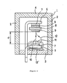
- the figure 1 shows a microcontact housing 1 formed of vertical walls 2, a bottom 3 and a cover 4.
- the housing encloses lower fixed terminals 5 and upper 6, having an electrical contact layer 7 and whose support crosses the bottom 3 of the case.
- the overall dimensions of the housing 1 are of the order of 10 to 20 mm in height, 30 to 50 mm in length and 10 to 20 mm in width.
- a movable contact 8, comprising two contact layers 9, is mounted by means not shown to move between the upper position where it is in contact with the upper terminal 6 and the lower position where it is in contact with the lower terminal 5.
- the distance e separating the moving contact from the lower fixed terminal 5 is the gap, in the space of which an electric arc is formed symbolized by the dashed straight line 10 in the absence of arc deflection means.
- the side walls 2 are constituted by permanent magnets, or incorporate such magnets, so as to permanently create a transverse magnetic field at the air gap symbolized by the field lines 11, thanks to which the arc is deviated along the path symbolized by the curved line 12, longer than the line 10.
- the figure 2 shows the arc duration / intensity curves for a microswitch feeding a 5 mH impedance circuit under a voltage of 28 V, on the one hand without magnet according to the invention and on the other hand with magnet. It is found that without a magnet, the arc duration increases rapidly up to about 20 A and very rapidly above, to a point of rupture where the arc is permanent and causes the burning of the contacts and the apparatus . On the contrary, with the magnetic field according to the invention, the same microswitch has shown a relative constancy of the arc duration when the power increases.
- FIGS. 3 and 4 show an alternative embodiment in which two housings 1, 1 'of microswitches are partially joined by one side and surmounted by a common reported magnet 13 (shown in dashed) straddling the two microswitches.
- the figure 5 shows a housing substantially identical to that of the figure 1 , except that the walls 2 are not magnetic.
- the cover 4 can be separable, as shown, or the vertical walls 2 and the cover 4 can be in one piece, the bottom 3 being removable.
- the device for creating a magnetic field consisting of a permanent magnet 13 'oriented North South is disposed on the bottom 3, under the lower contact 5, so as to permanently create a magnetic field transverse to the air gap symbolized by the field lines 11, by means of which the arc is deflected along the path symbolized by the curved line 12, longer than the line 10.
- the magnet 13 ' may be constituted by a small pellet which is disposed below the lower limit 5.
Landscapes
- Switch Cases, Indication, And Locking (AREA)
- Contacts (AREA)
- Arc-Extinguishing Devices That Are Switches (AREA)
- Push-Button Switches (AREA)
- Switches Operated By Changes In Physical Conditions (AREA)
Description
- La présente invention concerne un microcontact, pour les applications aux forts courants du domaine automobile. Par forts courants du domaine automobile, on entend des courants qui vont actuellement couramment de 12 V en courant continu pour les automobiles, à 24 V pour les poids lourds et même jusqu'à 42 V selon les normes nouvelles prévues, c'est-à-dire des courants relativement faibles par rapport à d'autres applications industrielles.
- Les microcontacts connus utilisés pour la commutation de courant dans ces applications comprennent un contact mobile entre une position supérieure et une position inférieure où il est en contact électrique avec une borne fixe. La position supérieure peut être une position de repos ou, dans le cas des contacts à deux bornes, une position active de contact avec une seconde borne fixe. L'entrefer, c'est-à-dire la distance entre le contact mobile en position supérieure et la borne fixe inférieure est lié aux paramètres suivants :
- Tension d'utilisation,
- Courant d'utilisation,
- Type de charge (self, lampes, résistances, ...)
- L'électrification des fonctions dans le domaine automobile amène la commutation de puissances de plus en plus élevées, ce qui oblige à augmenter les entrefers et donc l'encombrement des appareils. De plus, il y a une accélération de la dégradation des contacts.
- Le but de l'invention est de pallier ces inconvénients.
- L'invention atteint son but grâce à un microcontact selon la revendication 1.
- On connaît dans le cadre des applications industrielles aux courants élévés divers moyens pour souffler l'arc électrique dans un disjoncteur de puissance, un interrupteur ou un relais. Dans les dispositifs les plus encombrants, on peut utiliser le soufflage par air ou le soufflage magnétique, notamment à l'aide de bobines d'électroaimants ou de gros aimants permanents (cf.
US 3 943 316 ,US 4 302 644 ) . Dans les cas où l'encombrement doit être plus limité, comme dans le cas de certains relais, on a déjà proposé l'utilisation d'aimants permanents agencés de manière à tenir relativement peu de place (cf.FR 2491676 - Selon la présente invention, la superposition du champ magnétique dans l'entrefer permet, grâce à l'allongement de l'arc, d'utiliser un microcontact destiné en principe à des applications en 12 V, dans des applications à 24 V ou même à 42 V alors que jusque-là, on était obligé de fabriquer des microcontacts spécifiquement destinés à ces tensions nominales. Autrement dit, l'invention permet de surclasser un microcontact existant.
- Les microcontacts, ou contacts miniatures, ou contacts sub-miniatures, concernés par l'invention sont du type dans lesquels l'entrefer est couramment de l'ordre de 0,8 à 1 mm (pour les applications en 12 V). Les microcontacts correspondants spécifiques pour les applications en 24 V ont couramment un entrefer d'environ 2 mm, mais peuvent, grâce à l'invention conserver leur entrefer d'environ 1 mm.
- Le dispositif de création de champ magnétique selon l'invention peut être constitué par un ou plusieurs aimants permanents attachés au boîtier du microcontact ou surmoulés dans celui-ci. Les aimants sont de préférence des aimants plats montés verticalement sur un, deux ou trois faces dans la zone des contacts du microcontact.
- Selon une variante particulièrement avantageuse, l'aimant est un aimant rapporté unique disposé à l'intérieur du boîtier à proximité des bornes électriques. L'aimant est un aimant orienté Nord-Sud disposé transversalement aux contacts de manière à créer les lignes de champ transversales souhaitées. Cet aimant peut être rapporté de manière économique, de préférence par clipsage ou surmoulage, entre l'un des contacts fixes et le boîtier ; il est situé sous la borne fixe inférieure, parallèlement au fond du boîtier, le fond du boîtier étant amovible, et rend cette partie plus accessible pour y fixer l'aimant.
- Elle repose sur la constatation qu'un aimant unique, en particulier un aimant unique de type terres rares (champ rémanent important, par exemple supérieur à 500 millitesla) convenablement placé permet également de créer un champ magnétique convenable dans l'entrefer. De plus, son encombrement est vraiment minimal.
- Avantageusement, dans toutes les solutions, on impose au contact mobile une vitesse élevée et indépendante de la vitesse d'actionnement du microcontact afin de limiter la durée de l'arc électrique, ce qui permet d'obtenir une rupture brusque et évite la dégradation des contacts.
- D'autres avantages et caractéristiques apparaîtront à la lecture de la description de l'invention, ainsi que des dessins annexés sur lesquels :
- la
figure 1 est une vue en coupe schématique d'un microcontact conforme à l'invention ; - la
figure 2 est un graphique comparant la durée d'arc par rapport à l'intensité, entre un microcontact traditionnel et un microcontact conforme à l'invention ; - la
figure 3 est un schéma en perspective de deux microcontacts accolés et munis d'un dispositif d'aimantation commun ; - la
figure 4 est une coupe schématique IV-IV d'un des microcontacts de lafigure 3 ; - la
figure 5 est une vue analogue à lafigure 1 d'une autre variante préférée de l'invention, utilisant un aimant unique. - La
figure 1 montre un boîtier de microcontact 1 formé de parois verticales 2, d'un fond 3 et d'un couvercle 4. Le boîtier renferme des bornes fixes inférieure 5 et supérieure 6, comportant une couche de contact électrique 7 et dont le support traverse le fond 3 du boîtier. Les dimensions globales du boîtier 1 sont de l'ordre de 10 à 20 mm de hauteur, 30 à 50 mm de longueur et 10 à 20 mm de largeur. Un contact mobile 8, comportant deux couches de contact 9, est monté par des moyens non représentés pour se déplacer entre la position haute où il est en contact avec la borne supérieure 6 et la position basse où il est contact avec la borne inférieure 5. La distance e séparant le contact mobile de la borne fixe inférieure 5 est l'entrefer, dans l'espace duquel se forme un arc électrique symbolisé par la ligne droite pointillée 10 en l'absence de moyens de déviation d'arc. Selon l'invention, les parois latérales 2 sont constituées par des aimants permanents, ou incorporent de tels aimants, de manière à créer en permanence un champ magnétique transversal à l'entrefer symbolisé par les lignes de champ 11, grâce auquel l'arc est dévié selon le chemin symbolisé par la ligne courbe 12, plus longue que la ligne 10. - La
figure 2 montre les courbes durée d'arc/intensité pour un microcontact alimentant un circuit d'impédance 5 mH sous une tension de 28 V, d'une part sans aimant conforme à l'invention et d'autre part avec aimant. On constate que sans aimant, la durée d'arc augmente rapidement jusqu'à environ 20 A et très rapidement au-dessus, jusqu'à un point de rupture où l'arc est permanent et entraîne la brûlure des contacts et de l'appareil. Au contraire, avec le champ magnétique conforme à l'invention, le même microcontact a montré une relative constance de la durée d'arc quand la puissance croît. - Les
figures 3 et 4 montrent une variante de réalisation dans laquelle deux boîtiers 1, 1' de microcontacts sont accolés partiellement par une face et surmontés par un aimant rapporté commun 13 (représenté en tirets) à cheval sur les deux microcontacts. - La
figure 5 montre un boîtier sensiblement identique à celui de lafigure 1 , si ce n'est que les parois 2 ne sont pas magnétiques. Le couvercle 4 peut être séparable, comme représenté, ou bien les parois verticales 2 et le couvercle 4 peuvent être d'un seul tenant, le fond 3 étant seul amovible. Le dispositif de création de champ magnétique étant constitué par un aimant permanent 13' orienté Nord Sud est disposé sur le fond 3, sous le contact inférieur 5, de manière de manière à créer en permanence un champ magnétique transversal à l'entrefer symbolisé par les lignes de champ 11, grâce auquel l'arc est dévié selon le chemin symbolisé par la ligne courbe 12, plus longue que la ligne 10. L'aimant 13' peut être constitué par une petite pastille qu'on vient disposer sous la borne inférieure 5.
Claims (2)
- Microcontact pour courant continu de l'ordre de 10 V à 50 V comprenant:- un boîtier (1),- une structure dans ce boîtier comportant un contact (8) mobile entre une première position où il est en contact électrique avec une borne fixe électrique (5) portée par le fond (3) du boîtier (1) et une seconde position où il n'est plus en contact avec ladite borne fixe (5), l'entrefer (e) entre les deux positions étant de l'ordre du millimètre et,- un dispositif de création de champ magnétique transversal dans la zone de l'entrefer (e), le dispositif de création de champ magnétique comprenant un aimant permanent rapporté unique à champ rémanent important,caractérisé en ce que le fond du boîtier est amovible et en ce que l'aimant est disposé à l'intérieur du boîtier entre la borne fixe électrique et le fond amovible.
- Microcontact selon la revendication 1, caractérisé en ce que l'aimant (13') est rapporté par clipsage ou surmoulage.
Applications Claiming Priority (5)
| Application Number | Priority Date | Filing Date | Title |
|---|---|---|---|
| FR0114399A FR2831985B1 (fr) | 2001-11-07 | 2001-11-07 | Microcontact a entrefer reduit et procede associe de surclassement de microcontact |
| FR0114399 | 2001-11-07 | ||
| FR0207010 | 2002-06-07 | ||
| FR0207010A FR2840727B1 (fr) | 2002-06-07 | 2002-06-07 | Microcontact a entrefer reduit |
| PCT/FR2002/003546 WO2003041103A1 (fr) | 2001-11-07 | 2002-10-16 | Microcontact a entrefer reduit et procede associe de surclassement de microcontact |
Publications (2)
| Publication Number | Publication Date |
|---|---|
| EP1451841A1 EP1451841A1 (fr) | 2004-09-01 |
| EP1451841B1 true EP1451841B1 (fr) | 2008-07-02 |
Family
ID=26213250
Family Applications (1)
| Application Number | Title | Priority Date | Filing Date |
|---|---|---|---|
| EP02793166A Expired - Lifetime EP1451841B1 (fr) | 2001-11-07 | 2002-10-16 | Microcontact a entrefer reduit et procede associe de surclassement de microcontact |
Country Status (4)
| Country | Link |
|---|---|
| EP (1) | EP1451841B1 (fr) |
| AT (1) | ATE400058T1 (fr) |
| DE (1) | DE60227410D1 (fr) |
| WO (1) | WO2003041103A1 (fr) |
Families Citing this family (1)
| Publication number | Priority date | Publication date | Assignee | Title |
|---|---|---|---|---|
| EP1760744A1 (fr) * | 2005-09-02 | 2007-03-07 | Abb Research Ltd. | Disjoncteur à vide à arc mouvant par action d'un aimant permanent |
Family Cites Families (3)
| Publication number | Priority date | Publication date | Assignee | Title |
|---|---|---|---|---|
| US3042778A (en) * | 1959-04-15 | 1962-07-03 | Albert E Anderson | Electrical contacting device |
| FR2491676A1 (fr) * | 1980-10-03 | 1982-04-09 | Thomson Csf | Relais electromagnetique |
| JPH09320376A (ja) * | 1996-05-23 | 1997-12-12 | Kawamura Electric Inc | 直流用開閉器 |
-
2002
- 2002-10-16 EP EP02793166A patent/EP1451841B1/fr not_active Expired - Lifetime
- 2002-10-16 AT AT02793166T patent/ATE400058T1/de not_active IP Right Cessation
- 2002-10-16 WO PCT/FR2002/003546 patent/WO2003041103A1/fr not_active Ceased
- 2002-10-16 DE DE60227410T patent/DE60227410D1/de not_active Expired - Lifetime
Also Published As
| Publication number | Publication date |
|---|---|
| DE60227410D1 (de) | 2008-08-14 |
| EP1451841A1 (fr) | 2004-09-01 |
| WO2003041103A1 (fr) | 2003-05-15 |
| ATE400058T1 (de) | 2008-07-15 |
Similar Documents
| Publication | Publication Date | Title |
|---|---|---|
| EP1995747B1 (fr) | Chambre de coupure et disjoncteur équipé d'une telle chambre de coupure | |
| EP1556873B1 (fr) | Dispositif de commutation electrique, relais et appareil electrique comportant un tel dispositif | |
| EP2061051B1 (fr) | Chambre de coupure et disjoncteur équipé d'une telle chambre de coupure | |
| FR2491676A1 (fr) | Relais electromagnetique | |
| FR3050311A1 (fr) | Disjoncteur electrique a courant continu | |
| FR2970372A1 (fr) | Contacteur magnetique | |
| FR2622736A1 (fr) | Disjoncteur basse tension, a courant continu, et a joues de guidage de l'arc | |
| FR2616008A1 (fr) | Appareil de coupure etanche a l'air comportant des moyens de soufflage d'arc | |
| EP3736844B1 (fr) | Interrupteur électrique à courant continu comportant un pôle limiteur | |
| FR2595865A1 (fr) | Interrupteur electrique, plus particulierement son actionneur magnetique de contact a haute vitesse | |
| EP0874380B1 (fr) | Dispositif de coupure électrique pour basse et haute tension | |
| WO2006134452A8 (fr) | Disjoncteur electromecanique et procede de coupure du courant dans ce disjoncteur | |
| EP0678886B1 (fr) | Disjoncteur à moyenne ou haute tension | |
| EP1451841A1 (fr) | Microcontact a entrefer reduit et procede associe de surclassement de microcontact | |
| FR2831985A1 (fr) | Microcontact a entrefer reduit et procede associe de surclassement de microcontact | |
| FR2494032A1 (fr) | Dispositif de commutation electrique et module de commutation pourvu dudit dispositif | |
| FR2473217A1 (fr) | Interrupteur a contacts mouilles et a commande magnetique, et relais electrique comportant un tel interrupteur | |
| EP0061382B1 (fr) | Relais électro-magnétique à position de fonctionnement indifférente | |
| FR2623935A1 (fr) | Systeme de contacts isole par une chambre de coupure et utilisation pour un relais electromagnetique a haute compacite | |
| FR2634942A1 (fr) | Dispositif d'extinction d'arc electrique pour un commutateur basse tension limitant le courant de court-circuit | |
| FR2511187A1 (fr) | Interrupteur electrique comprenant des toles d'extinction en un materiau conducteur de l'electricite et pouvant etre aimantees, dans lesquelles la face frontale presente au moins un evidement | |
| EP0713232A1 (fr) | Chambre de coupure d'un disjoncteur électrique | |
| WO2025046190A1 (fr) | Contacteur électrique haute tension comprenant quatre chambres de coupure | |
| WO2025114661A1 (fr) | Commutateur pour haute tension continue | |
| WO2024134100A1 (fr) | Chambre de coupure a haute tension |
Legal Events
| Date | Code | Title | Description |
|---|---|---|---|
| PUAI | Public reference made under article 153(3) epc to a published international application that has entered the european phase |
Free format text: ORIGINAL CODE: 0009012 |
|
| 17P | Request for examination filed |
Effective date: 20040429 |
|
| AK | Designated contracting states |
Kind code of ref document: A1 Designated state(s): AT BE BG CH CY CZ DE DK EE ES FI FR GB GR IE IT LI LU MC NL PT SE SK TR |
|
| AX | Request for extension of the european patent |
Extension state: AL LT LV MK RO SI |
|
| 17Q | First examination report despatched |
Effective date: 20070411 |
|
| GRAP | Despatch of communication of intention to grant a patent |
Free format text: ORIGINAL CODE: EPIDOSNIGR1 |
|
| GRAS | Grant fee paid |
Free format text: ORIGINAL CODE: EPIDOSNIGR3 |
|
| GRAA | (expected) grant |
Free format text: ORIGINAL CODE: 0009210 |
|
| AK | Designated contracting states |
Kind code of ref document: B1 Designated state(s): AT BE BG CH CY CZ DE DK EE ES FI FR GB GR IE IT LI LU MC NL PT SE SK TR |
|
| REG | Reference to a national code |
Ref country code: GB Ref legal event code: FG4D Free format text: NOT ENGLISH |
|
| REG | Reference to a national code |
Ref country code: CH Ref legal event code: EP |
|
| REF | Corresponds to: |
Ref document number: 60227410 Country of ref document: DE Date of ref document: 20080814 Kind code of ref document: P |
|
| REG | Reference to a national code |
Ref country code: IE Ref legal event code: FG4D Free format text: LANGUAGE OF EP DOCUMENT: FRENCH |
|
| REG | Reference to a national code |
Ref country code: SE Ref legal event code: TRGR |
|
| PG25 | Lapsed in a contracting state [announced via postgrant information from national office to epo] |
Ref country code: ES Free format text: LAPSE BECAUSE OF FAILURE TO SUBMIT A TRANSLATION OF THE DESCRIPTION OR TO PAY THE FEE WITHIN THE PRESCRIBED TIME-LIMIT Effective date: 20081013 Ref country code: PT Free format text: LAPSE BECAUSE OF FAILURE TO SUBMIT A TRANSLATION OF THE DESCRIPTION OR TO PAY THE FEE WITHIN THE PRESCRIBED TIME-LIMIT Effective date: 20081202 |
|
| REG | Reference to a national code |
Ref country code: IE Ref legal event code: FD4D |
|
| PG25 | Lapsed in a contracting state [announced via postgrant information from national office to epo] |
Ref country code: BG Free format text: LAPSE BECAUSE OF FAILURE TO SUBMIT A TRANSLATION OF THE DESCRIPTION OR TO PAY THE FEE WITHIN THE PRESCRIBED TIME-LIMIT Effective date: 20081002 Ref country code: AT Free format text: LAPSE BECAUSE OF FAILURE TO SUBMIT A TRANSLATION OF THE DESCRIPTION OR TO PAY THE FEE WITHIN THE PRESCRIBED TIME-LIMIT Effective date: 20080702 Ref country code: FI Free format text: LAPSE BECAUSE OF FAILURE TO SUBMIT A TRANSLATION OF THE DESCRIPTION OR TO PAY THE FEE WITHIN THE PRESCRIBED TIME-LIMIT Effective date: 20080702 |
|
| BERE | Be: lapsed |
Owner name: DAV Effective date: 20081031 |
|
| PG25 | Lapsed in a contracting state [announced via postgrant information from national office to epo] |
Ref country code: EE Free format text: LAPSE BECAUSE OF FAILURE TO SUBMIT A TRANSLATION OF THE DESCRIPTION OR TO PAY THE FEE WITHIN THE PRESCRIBED TIME-LIMIT Effective date: 20080702 Ref country code: DK Free format text: LAPSE BECAUSE OF FAILURE TO SUBMIT A TRANSLATION OF THE DESCRIPTION OR TO PAY THE FEE WITHIN THE PRESCRIBED TIME-LIMIT Effective date: 20080702 Ref country code: IE Free format text: LAPSE BECAUSE OF FAILURE TO SUBMIT A TRANSLATION OF THE DESCRIPTION OR TO PAY THE FEE WITHIN THE PRESCRIBED TIME-LIMIT Effective date: 20080702 |
|
| PLBE | No opposition filed within time limit |
Free format text: ORIGINAL CODE: 0009261 |
|
| STAA | Information on the status of an ep patent application or granted ep patent |
Free format text: STATUS: NO OPPOSITION FILED WITHIN TIME LIMIT |
|
| PG25 | Lapsed in a contracting state [announced via postgrant information from national office to epo] |
Ref country code: SK Free format text: LAPSE BECAUSE OF FAILURE TO SUBMIT A TRANSLATION OF THE DESCRIPTION OR TO PAY THE FEE WITHIN THE PRESCRIBED TIME-LIMIT Effective date: 20080702 Ref country code: MC Free format text: LAPSE BECAUSE OF NON-PAYMENT OF DUE FEES Effective date: 20081031 Ref country code: CZ Free format text: LAPSE BECAUSE OF FAILURE TO SUBMIT A TRANSLATION OF THE DESCRIPTION OR TO PAY THE FEE WITHIN THE PRESCRIBED TIME-LIMIT Effective date: 20080702 |
|
| REG | Reference to a national code |
Ref country code: CH Ref legal event code: PL |
|
| 26N | No opposition filed |
Effective date: 20090403 |
|
| PG25 | Lapsed in a contracting state [announced via postgrant information from national office to epo] |
Ref country code: BE Free format text: LAPSE BECAUSE OF NON-PAYMENT OF DUE FEES Effective date: 20081031 |
|
| PG25 | Lapsed in a contracting state [announced via postgrant information from national office to epo] |
Ref country code: LI Free format text: LAPSE BECAUSE OF NON-PAYMENT OF DUE FEES Effective date: 20081031 Ref country code: CH Free format text: LAPSE BECAUSE OF NON-PAYMENT OF DUE FEES Effective date: 20081031 |
|
| PG25 | Lapsed in a contracting state [announced via postgrant information from national office to epo] |
Ref country code: CY Free format text: LAPSE BECAUSE OF FAILURE TO SUBMIT A TRANSLATION OF THE DESCRIPTION OR TO PAY THE FEE WITHIN THE PRESCRIBED TIME-LIMIT Effective date: 20080702 Ref country code: LU Free format text: LAPSE BECAUSE OF NON-PAYMENT OF DUE FEES Effective date: 20081016 |
|
| PG25 | Lapsed in a contracting state [announced via postgrant information from national office to epo] |
Ref country code: TR Free format text: LAPSE BECAUSE OF FAILURE TO SUBMIT A TRANSLATION OF THE DESCRIPTION OR TO PAY THE FEE WITHIN THE PRESCRIBED TIME-LIMIT Effective date: 20080702 |
|
| PG25 | Lapsed in a contracting state [announced via postgrant information from national office to epo] |
Ref country code: GR Free format text: LAPSE BECAUSE OF FAILURE TO SUBMIT A TRANSLATION OF THE DESCRIPTION OR TO PAY THE FEE WITHIN THE PRESCRIBED TIME-LIMIT Effective date: 20081003 |
|
| REG | Reference to a national code |
Ref country code: FR Ref legal event code: PLFP Year of fee payment: 14 |
|
| REG | Reference to a national code |
Ref country code: FR Ref legal event code: PLFP Year of fee payment: 15 |
|
| PGFP | Annual fee paid to national office [announced via postgrant information from national office to epo] |
Ref country code: GB Payment date: 20161014 Year of fee payment: 15 |
|
| PGFP | Annual fee paid to national office [announced via postgrant information from national office to epo] |
Ref country code: IT Payment date: 20161011 Year of fee payment: 15 Ref country code: SE Payment date: 20161012 Year of fee payment: 15 |
|
| REG | Reference to a national code |
Ref country code: FR Ref legal event code: PLFP Year of fee payment: 16 |
|
| PGFP | Annual fee paid to national office [announced via postgrant information from national office to epo] |
Ref country code: NL Payment date: 20170918 Year of fee payment: 16 |
|
| REG | Reference to a national code |
Ref country code: SE Ref legal event code: EUG |
|
| GBPC | Gb: european patent ceased through non-payment of renewal fee |
Effective date: 20171016 |
|
| PG25 | Lapsed in a contracting state [announced via postgrant information from national office to epo] |
Ref country code: GB Free format text: LAPSE BECAUSE OF NON-PAYMENT OF DUE FEES Effective date: 20171016 |
|
| PG25 | Lapsed in a contracting state [announced via postgrant information from national office to epo] |
Ref country code: SE Free format text: LAPSE BECAUSE OF NON-PAYMENT OF DUE FEES Effective date: 20171017 |
|
| REG | Reference to a national code |
Ref country code: FR Ref legal event code: PLFP Year of fee payment: 17 |
|
| PG25 | Lapsed in a contracting state [announced via postgrant information from national office to epo] |
Ref country code: IT Free format text: LAPSE BECAUSE OF NON-PAYMENT OF DUE FEES Effective date: 20171016 |
|
| REG | Reference to a national code |
Ref country code: NL Ref legal event code: MM Effective date: 20181101 |
|
| PG25 | Lapsed in a contracting state [announced via postgrant information from national office to epo] |
Ref country code: NL Free format text: LAPSE BECAUSE OF NON-PAYMENT OF DUE FEES Effective date: 20181101 |
|
| PGFP | Annual fee paid to national office [announced via postgrant information from national office to epo] |
Ref country code: DE Payment date: 20211008 Year of fee payment: 20 |
|
| PGFP | Annual fee paid to national office [announced via postgrant information from national office to epo] |
Ref country code: FR Payment date: 20211029 Year of fee payment: 20 |
|
| REG | Reference to a national code |
Ref country code: DE Ref legal event code: R071 Ref document number: 60227410 Country of ref document: DE |