EP1450557A2 - Apparatus and method for displaying on-screen display image in compound video device - Google Patents
Apparatus and method for displaying on-screen display image in compound video device Download PDFInfo
- Publication number
- EP1450557A2 EP1450557A2 EP04004036A EP04004036A EP1450557A2 EP 1450557 A2 EP1450557 A2 EP 1450557A2 EP 04004036 A EP04004036 A EP 04004036A EP 04004036 A EP04004036 A EP 04004036A EP 1450557 A2 EP1450557 A2 EP 1450557A2
- Authority
- EP
- European Patent Office
- Prior art keywords
- video device
- osd
- type
- image
- data
- Prior art date
- Legal status (The legal status is an assumption and is not a legal conclusion. Google has not performed a legal analysis and makes no representation as to the accuracy of the status listed.)
- Ceased
Links
Images





Classifications
-
- H—ELECTRICITY
- H04—ELECTRIC COMMUNICATION TECHNIQUE
- H04N—PICTORIAL COMMUNICATION, e.g. TELEVISION
- H04N5/00—Details of television systems
- H04N5/44—Receiver circuitry for the reception of television signals according to analogue transmission standards
- H04N5/445—Receiver circuitry for the reception of television signals according to analogue transmission standards for displaying additional information
- H04N5/44504—Circuit details of the additional information generator, e.g. details of the character or graphics signal generator, overlay mixing circuits
-
- H—ELECTRICITY
- H04—ELECTRIC COMMUNICATION TECHNIQUE
- H04N—PICTORIAL COMMUNICATION, e.g. TELEVISION
- H04N21/00—Selective content distribution, e.g. interactive television or video on demand [VOD]
- H04N21/40—Client devices specifically adapted for the reception of or interaction with content, e.g. set-top-box [STB]; Operations thereof
- H04N21/41—Structure of client; Structure of client peripherals
- H04N21/4104—Peripherals receiving signals from specially adapted client devices
- H04N21/4112—Peripherals receiving signals from specially adapted client devices having fewer capabilities than the client, e.g. thin client having less processing power or no tuning capabilities
-
- H—ELECTRICITY
- H04—ELECTRIC COMMUNICATION TECHNIQUE
- H04N—PICTORIAL COMMUNICATION, e.g. TELEVISION
- H04N21/00—Selective content distribution, e.g. interactive television or video on demand [VOD]
- H04N21/40—Client devices specifically adapted for the reception of or interaction with content, e.g. set-top-box [STB]; Operations thereof
- H04N21/41—Structure of client; Structure of client peripherals
- H04N21/426—Internal components of the client ; Characteristics thereof
- H04N21/42653—Internal components of the client ; Characteristics thereof for processing graphics
-
- H—ELECTRICITY
- H04—ELECTRIC COMMUNICATION TECHNIQUE
- H04N—PICTORIAL COMMUNICATION, e.g. TELEVISION
- H04N21/00—Selective content distribution, e.g. interactive television or video on demand [VOD]
- H04N21/40—Client devices specifically adapted for the reception of or interaction with content, e.g. set-top-box [STB]; Operations thereof
- H04N21/43—Processing of content or additional data, e.g. demultiplexing additional data from a digital video stream; Elementary client operations, e.g. monitoring of home network or synchronising decoder's clock; Client middleware
- H04N21/431—Generation of visual interfaces for content selection or interaction; Content or additional data rendering
- H04N21/4312—Generation of visual interfaces for content selection or interaction; Content or additional data rendering involving specific graphical features, e.g. screen layout, special fonts or colors, blinking icons, highlights or animations
-
- H—ELECTRICITY
- H04—ELECTRIC COMMUNICATION TECHNIQUE
- H04N—PICTORIAL COMMUNICATION, e.g. TELEVISION
- H04N21/00—Selective content distribution, e.g. interactive television or video on demand [VOD]
- H04N21/40—Client devices specifically adapted for the reception of or interaction with content, e.g. set-top-box [STB]; Operations thereof
- H04N21/43—Processing of content or additional data, e.g. demultiplexing additional data from a digital video stream; Elementary client operations, e.g. monitoring of home network or synchronising decoder's clock; Client middleware
- H04N21/443—OS processes, e.g. booting an STB, implementing a Java virtual machine in an STB or power management in an STB
- H04N21/4432—Powering on the client, e.g. bootstrap loading using setup parameters being stored locally or received from the server
-
- H—ELECTRICITY
- H04—ELECTRIC COMMUNICATION TECHNIQUE
- H04N—PICTORIAL COMMUNICATION, e.g. TELEVISION
- H04N5/00—Details of television systems
- H04N5/76—Television signal recording
- H04N5/765—Interface circuits between an apparatus for recording and another apparatus
-
- H—ELECTRICITY
- H04—ELECTRIC COMMUNICATION TECHNIQUE
- H04N—PICTORIAL COMMUNICATION, e.g. TELEVISION
- H04N5/00—Details of television systems
- H04N5/76—Television signal recording
- H04N5/84—Television signal recording using optical recording
- H04N5/85—Television signal recording using optical recording on discs or drums
Definitions
- the present invention relates to a compound video device including a first video device, such as a video cassette recorder (VCR), and a second video device, such as a digital versatile disc (DVD) player and recorder, integrally formed with each other, and more particularly to an apparatus and method for displaying an on-screen display (OSD) image in a compound video device.
- a first video device such as a video cassette recorder (VCR)
- a second video device such as a digital versatile disc (DVD) player and recorder
- a compound video device including a first video device, such as a VCR, and a second video device, such as a DVD player, integrally formed with each other, has been developed and introduced to the market and has been commercially available.
- some devices include a VCR and a DVD player/recorder.
- the VCR functions to reproduce/output video and audio signals recorded on a video tape, or to record video and audio signals thereon.
- the DVD player functions to read/reproduce video and audio data from a DVD, which is a high-density optical disc.
- Some devices may also include the ability to record information to a DVD.
- the above-mentioned compound video device comprises, as shown in Fig. 1, a VCR part including a tape mechanism (for example, a tape deck) 10, a VCR system 11, a first microcomputer 12, an OSD generator 13 and a read only memory (ROM) 14.
- the DVD player part includes an optical disc playing portion 20, an optical pickup 21, a second microcomputer 22, the DVD system 23 and a flash memory 24.
- the compound video device further comprises an output unit 25 for outputting signals read/reproduced respectively by the VCR part and DVD player part to an external connection device such as a television.
- the ROM 14 stores OSD font data necessary for OSD image display in a VCR operation mode
- the flash memory 24 stores an OSD graphic image necessary for OSD image display in a DVD player operation mode.
- the first microcomputer 12 sets the current operation mode of the compound video device to the VCR operation mode in response to a user's key input to perform a corresponding operation. If an OSD image display in the VCR operation mode is required, the first microcomputer 12 reads the OSD font data stored in the ROM 14 and controls the OSD generator 13 such that a corresponding OSD image is outputted and displayed.
- the second microcomputer 22 receives the user's key input via the first microcomputer 12 and can set the current operation mode of the compound video device to the DVD player operation mode in response to the received key input.
- the second microcomputer 22 reads the OSD graphic image stored in the flash memory 24, and controls the DVD system 23 such that a corresponding OSD image is outputted and displayed.
- the user can view the OSD image outputted/displayed in the VCR operation mode or the OSD image outputted/displayed in the DVD player operation mode through the screen of the television connected with the compound video device.
- the user is further capable of simply and conveniently selecting a desired function or operation through the displayed OSD image.
- the above-mentioned compound video device has a disadvantage in that it needs both the ROM 14 and flash memory 24.
- the OSD font data required in the VCR operation mode is stored in the ROM 14, and the OSD graphic image required in the DVD player operation mode is stored in the flash memory 24.
- it is difficult to simplify the device's construction.
- it is necessary to replace the ROM installed in the device with a new one.
- An object of the invention is to solve at least the above problems and/or disadvantages and to provide at least the advantages described hereinafter.
- the present invention has been made in view of the above problems, and it is an object of the present invention to provide an apparatus and method for displaying an OSD image in a compound video device, wherein an OSD graphic image and OSD font data necessary for OSD image output are separately stored in one flash memory.
- any of the OSD font data and OSD graphic image separately stored in the flash memory may be selectively read and used in a corresponding one of first and second video device operation modes.
- Fig. 1 is a block diagram showing the construction of a related art compound video device
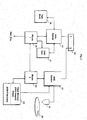
- Fig. 2 is a block diagram showing the construction of a compound video device to which an OSD image display apparatus and method according to a first embodiment of the present invention are applied;
- Fig. 3 is a view showing OSD graphic image data and OSD font data separately stored in a flash memory of the compound video device according to the first embodiment of the present invention
- Fig. 4 is a flow chart illustrating an OSD image display method according to an embodiment of the present invention.
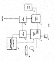
- Fig. 5 is a block diagram showing the construction of a compound video device to which an OSD image display apparatus and method according to a second embodiment of the present invention are applied;
- Fig. 6 is a view showing OSD graphic images corresponding, respectively, to first and second video devices separately stored in a flash memory of the compound video device according to the second embodiment of the present invention.
- Fig. 7 is a flow chart illustrating another OSD image display method according to the present invention.
- the compound video device comprises a VCR part including a tape mechanism 10, a VCR system 11, a first microcomputer 12 and an OSD generator 13.
- the device further includes a DVD player part including an optical disc portion 20, an optical pickup 21, a second microcomputer 22, a DVD system 23 and a flash memory 24.
- the DVD system will primarily be described as a DVD player. However, in some embodiments of the invention, the DVD system may include both playing and recording capabilities.
- the compound video device further comprises an output unit 25 for outputting signals read/reproduced respectively by the VCR part and DVD player part to an external connection device such as a television.
- the flash memory 24 separately stores OSD graphic image necessary for an OSD image display in a DVD player operation mode and OSD font data necessary for an OSD image display in a VCR operation mode.
- the flash memory 24 is preferably partitioned into two areas, a first area Area 1 and a second area Area 2, as shown in Fig. 3.
- Area 1 includes a plurality of memory locations Add_k - Add_k+p for storing a plurality of OSD graphic images OSD_Graphic_Image#1 - OSD_Graphic_Image#m.
- OSD graphic image information OSD_Graphic_Image_Info is stored in Area 1.
- the OSD graphic image information contains information regarding the number of the OSD graphic images (Nunber_of_OSD_Graphic_Image), information regarding a write start address of the OSD graphic images (Start_Address_OSD_Graphic_Image), and information regarding the size of the OSD graphic images (Size of OSD_Graphic_Image).
- Area 2 includes a plurality of memory locations Add_s - Add_s+q for storing a plurality of OSD font data (OSD_Font_Data#1 - OSD_Font_Data#n), as well as OSD font data information (OSD_Font_Data_Info).
- the OSD font data information contains information regarding the number of the OSD font data (Number_of_OSD_Font_Data), information regarding a write start address of the OSD font data (Start_Address_OSD_Font_Data), and information regarding the size of the OSD font data (Size_of_OSD_Font_Data).
- the first microcomputer 12 sets the current operation mode of the compound video device to the VCR operation mode in response to a user's key input to perform a corresponding operation, as stated previously. If an OSD image display in the VCR operation mode is required, the first microcomputer 12 requests and receives a desired one of the OSD font data stored in the second area of the flash memory 24 via an interface with the second microcomputer 22, and controls the OSD generator 13 such that a corresponding OSD image is outputted and displayed.
- the second microcomputer 22 receives the user's key input via the first microcomputer 12 and sets the current operation mode of the compound video device to the DVD player operation mode in response to the received key input to perform a corresponding operation. Where an OSD image display in the DVD player operation mode is required, the second microcomputer 22 reads a desired one of the OSD graphic images stored in the first area of the flash memory 24, and controls the DVD system 23 such that a corresponding OSD image is outputted and displayed, as will hereinafter be described in detail.
- Fig. 4 is a flow chart illustrating the OSD image display method according to the first embodiment of the present invention.
- the first microcomputer 12 performs a system booting operation for control of the respective components corresponding to the VCR part and the second microcomputer 22 performs a system booting operation for control of the respective components corresponding to the DVD player part (S11).
- the first microcomputer 12 sets the current operation mode of the compound video device to the VCR operation mode in response to a key input from the user, or transfers the key input to the second microcomputer 22 so that the microcomputer 22 can set the current operation mode to the DVD player operation mode.
- the first microcomputer 12 controls the VCR system 11 in response to the user's request to drive the tape mechanism 10.
- the first microcomputer 12 performs a reproduction operation of reading/reproducing video and audio signals from a video tape (not shown) loaded in the tape mechanism 10, or a recording operation of recording video and audio signals on the video tape (S13).
- the first microcomputer 12 generates a command for requesting the second microcomputer 22 to read/transfer OSD font data for output/display of an OSD image necessary for the reproduction operation or recording operation, and transfers the generated command to the second microcomputer 22 (S14).
- the second microcomputer 22 reads the OSD font data separately stored in Area 2 of the flash memory 24 and transfers the read OSD font data to the first microcomputer 12 (S15).
- the first microcomputer 12 receives the OSD font data transferred from the second microcomputer 22 and controls the OSD generator 13 to perform a series of operations of outputting/displaying the OSD image necessary for the reproduction operation or recording operation in the VCR part (S16). Thereafter, in the case where the user selects and requests a desired operation or function using the OSD image outputted/displayed in the above manner, the first microcomputer 12 performs the corresponding operation or function (S20).
- the second microcomputer 22 controls the DVD system 23 to perform a DVD reproduction operation of reading/reproducing video and audio data recorded on an optical disc, for example, a DVD loaded in the optical disk portion 20 (S18).
- the second microcomputer 22 For output/display of an OSD image necessary for the DVD reproduction operation, the second microcomputer 22 reads an associated one of the OSD graphic images separately stored in Area 1 of the flash memory 24, outputs the read OSD graphic image to the DVD system 23 and controls the DVD system 23 to perform a series of operations of outputting/displaying the OSD image necessary for the reproduction operation in the DVD player part (S19). Thereafter, when the user selects and requests a desired operation or function using the OSD image outputted/displayed in the above manner, the second microcomputer 22 performs the corresponding operation or function (S20).
- Fig. 5 is a block diagram showing the construction of a compound video device to which an OSD image display apparatus and method according to a second embodiment of the present invention are applied.
- the compound video device comprises a VCR part including a tape mechanism 10, a VCR system 11 and a first microcomputer 12.
- the DVD player part includes an optical disc portion 20, an optical pickup 21, a second microcomputer 22, a DVD system 23 and a flash memory 24.
- an analog signal reproduced by the VCR system 11 is analog-to-digital (A/D) converted by an A/D converter (not denoted by a reference numeral) in the DVD system 23.
- the signal is subjected to a digital signal process, and is then output through an output unit 25, which is connected to an external connection device such as a television.
- the flash memory 24 separately stores an OSD graphic image (referred to hereinafter as an OSD graphic image for a DVD) necessary for OSD image display in a DVD player operation mode and an OSD graphic image (referred to hereinafter as an OSD graphic image for a VCR) necessary for OSD image display in a VCR operation mode.
- the flash memory 24 is preferably partitioned into a first area Area 1 and a second area Area 2, as shown in Fig. 6.
- Area 1 includes a plurality of memory locations Add_k - Add_k+p for storing a plurality of OSD graphic images for the DVD OSD_Graphic_Image#1 - OSD_Graphic_Image#s.
- OSD graphic image information for the DVD (OSD_Graphic_Image_Info) is also stored in Area 1.
- Area 2 includes a plurality of memory locations Add_s - Add_s+q for storing a plurality of OSD graphic images for the VCR OSD_Graphic_Image#1-OSD_Graphic_Image#p.
- OSD graphic image information for the VCR OSD_Graphic_Image_Info is also stored in Area 2.
- the OSD graphic image information for the DVD and the OSD graphic image information for the VCR each contain information regarding the number of the OSD graphic images (Number_of_OSD_Graphic_Image), information regarding a write start address of the OSD graphic images (Start_Address_OSD_Graphic_Image), and information regarding the size of the OSD graphic images (Size_of_OSD_Graphic_Image).
- the first microcomputer 12 sets the current operation mode of the compound video device to the VCR operation mode in response to a user's key input to perform a corresponding operation, as stated previously. If an OSD image display in the VCR operation mode is required, the first microcomputer 12 performs an interface with the second microcomputer 22.
- the second microcomputer 22 selects and reads a desired one of the OSD graphic images for the VCR stored in the second area of the flash memory 24, and controls the DVD system 23 to perform a series of operations of overlapping/outputting the read OSD graphic image for the VCR, A/D-converting an analog signal reproduced by the VCR system 11, and carrying out the digital signal process with respect to the A/D-converted signal.
- the second microcomputer 22 sets the current operation mode of the compound video device to the DVD player operation mode in response to the user's key input received via the first microcomputer 12 to perform a corresponding operation.
- the second microcomputer 22 reads a desired one of the OSD graphic images for the DVD stored in the first area of the flash memory 24 and controls the DVD system 23 such that a corresponding OSD image is outputted and displayed, as will hereinafter be described in detail.
- Fig. 7 is a flow chart illustrating the OSD image display method according to the second embodiment of the present invention.
- the first microcomputer 12 performs a system booting operation for control of the respective components corresponding to the VCR part and the second microcomputer 22 performs a system booting operation for control of the respective components corresponding to the DVD player part (S51).
- the first microcomputer 12 sets the current operation mode of the compound video device to the VCR operation mode in response to a key input from the user, or transfers the key input to the second microcomputer 22 so that the microcomputer 22 can set the current operation mode to the DVD player operation mode.
- the first microcomputer 12 controls the VCR system 11 in response to the user's request to drive the tape mechanism 10.
- the first microcomputer 12 performs a reproduction operation of reading/reproducing video and audio signals from a video tape (not shown) loaded in the tape mechanism 10, or a recording operation of recording video and audio signals on the video tape (S53).
- the DVD system 23 A/D-converts an analog signal reproduced by the VCR system 11, performs the digital signal process for the A/D-converted signal in the same manner as that for a DVD image and then outputs the resulting digital signal to an external connection device (S54).
- the first microcomputer 12 upon receiving a VCR OSD image display request from the user (S55), the first microcomputer 12 performs an interface with the second microcomputer 22, which then selects and reads an OSD graphic image for the VCR corresponding to a VCR OSD image requested by the user from the flash memory 24. Then, the DVD system 23 outputs the OSD graphic image for the VCR selected and read in the above manner and the reproduced VCR signal subjected to the same digital signal process as that for the DVD image, in an overlapped manner, or in such a manner that the OSD graphic image for the VCR overlaps the reproduced VCR signal (S56).
- the reproduced analog VCR signal from the VCR system 11 is subjected to the same digital signal process as that for the DVD image by the DVD system 23, thereby enabling the OSD graphic image for the VCR to be normally displayed while overlapping the reproduced VCR signal.
- the second microcomputer 22 controls the DVD system 23 to perform a DVD reproduction operation of reading/reproducing video and audio data recorded on an optical disc, for example, a DVD loaded in the optical disk portion 20 (S58).
- the second microcomputer 22 For output/display of an OSD image necessary for the DVD reproduction operation, the second microcomputer 22 reads an associated one of the OSD graphic images for the DVD separately stored in Area 1 of the flash memory 24, outputs the read OSD graphic image to the DVD system 23 and controls the DVD system 23 to perform a series of operations of outputting/displaying the OSD image necessary for the reproduction operation in the DVD player part (S59).
- the first microcomputer 12 and the second microcomputer 22 perform the corresponding operation or function through an interface therebetween (S60).
- nonvolatile memory capable of updating/storing data may be used instead of the flash memory 24.
- the present invention provides an apparatus and method for displaying an OSD image in a compound video device, which can significantly simplify the construction of the compound video device.
- New OSD font data for a first video device and new OSD graphic images for a second video device, or new OSD graphic images for the first and second video devices can be updated/stored in a flash memory, or be simply replaced for existing ones.
- the DVD system may include only a DVD player, or both a DVD player and a DVD recorder. This, the foregoing description and the following claims should not be limited to just devices having one type of DVD system.
Landscapes
- Engineering & Computer Science (AREA)
- Multimedia (AREA)
- Signal Processing (AREA)
- Computer Graphics (AREA)
- General Engineering & Computer Science (AREA)
- Software Systems (AREA)
- Controls And Circuits For Display Device (AREA)
- Television Signal Processing For Recording (AREA)
Abstract
Description
Claims (25)
- A method for displaying an on-screen display (OSD) image in a compound video device, the compound video device including first and second video devices of different types, the method comprising the steps of:a) separately storing a first type of OSD data for the first type of video device and a second type of OSD data for the second type of video device in one memory device; andb) selecting and reading any one of the first type of OSD data and the second type of OSD data stored in said memory in a corresponding operation mode of said first video device or an operation mode of said second video device to output an OSD image.
- The method as set forth in claim 1, wherein said step a) includes separately storing the first type of OSD data and the second type of OSD data in one flash memory device.
- The method as set forth in claim 1 or 2, wherein a first microcomputer is connected to the first type of video device and a second microcomputer is connected to the second type of video device, and wherein when the device is operating in the first video device operation mode, said step b) includes the steps of:selecting and reading said first type of OSD data separately stored in said memory using the second microcomputer connected with the second type of video device; andcommunicating the first type of OSD data from the second microcomputer to the first microcomputer connected with the first type of video device.
- The method as set forth in any of claims 1 to 3, wherein when the device is operating in the second video device operating mode, said step b) includes selecting and reading said second type of OSD data separately stored in said memory to output/display said OSD image.
- The method as set forth in any of claims 1 to 4, wherein said first video device is a video cassette recorder (VCR) and said second video device is a digital versatile disc (DVD) player.
- The method as set forth in any of claims 1 to 5, wherein the step a) comprises:storing text used for menu items of an OSD for the first type of video device in a first portion of the memory; andstoring image data used in an OSD for the second type of video device in a second portion of the memory.
- The method as set forth in any of claims 1 to 6, further comprising the steps of converting an analog signal from said first video device into a digital signal with said second video device.
- The method as set forth in claim 7, further comprising overlapping OSD graphic image corresponding to said first video device selected and read from said memory with the converted digital signal to generate a display signal.
- The method as set forth in claim 1, wherein the step a) comprises:storing image data used for an OSD for the first type of video device in a first portion of the memory; andstoring image data used for an OSD for the second type of video device in a second portion of the memory.
- An apparatus for displaying an OSD image in a compound video device, the compound video device including first and second video devices of different types, the apparatus comprising:a single memory device having stored therein both a first type of OSD data used by the first video device and a second type of OSD data used by the second video device;a first signal processor configured to read the first type of OSD data stored in the memory and to output an OSD image when the apparatus is operating in a first video device operation mode;a second signal processor configured to read the second OSD data stored in the memory and to output an OSD image when the apparatus is operating in a second video device operation mode.
- The apparatus as set forth in claim 10, wherein said first video device is a VCR and said second video device is a DVD player.
- The apparatus as set forth in claim 10 or 11, wherein said memory is a flash memory configured to separately store said first type of OSD data and said second type of OSD data.
- The apparatus of any of claims 10 to 12, wherein the first type of OSD data is text data for an OSD of the first video device and the second type of OSD data is graphic image data for the second video device.
- The apparatus as set forth in any of claims 10 to 13, wherein said memory includes:a first area for storing a plurality of OSD graphic images and OSD graphic image information used by the second video device; anda second area for storing a plurality of OSD text data and OSD text data information used by the first video device.
- The apparatus as set forth in any of claims 10 to 14, wherein said apparatus further comprises:a first microcomputer for controlling components corresponding to said first video device; anda second microcomputer for controlling components corresponding to said second video device.
- The apparatus as set forth in claim 15, wherein said first microcomputer is adapted to select and read said first type of OSD data separately stored in said memory via an interface with said second microcomputer.
- The apparatus as set forth in claim 15 or 16, wherein said second microcomputer is adapted to select and read said second type of OSD data separately stored in said memory.
- An apparatus for displaying an OSD image in a compound video device, the compound video device including first and second video devices of different types, the apparatus comprising:a single memory device having stored therein both a first type of OSD data used by the first video device and a second type of OSD data used by the second video device;a first signal processor of the first video device configured to output an analog image signal; anda second signal processor of the second video device configured to output a digital image signal, wherein the second signal processor is also configured overlap the first type of OSD data read from the memory with an image signal from the first video device to produce an output image signal.
- The apparatus as set forth in claim 18, wherein the second signal processor is also configured to convert the analog image signal produced by the first signal processor into a digital image signal.
- The apparatus as set forth in claim 18 or 19, wherein said first video device is a VCR and said second video device is a DVD player.
- The apparatus as set forth in any of claims 18 to 20, wherein said memory is a flash memory configured to separately store said first type of OSD data and said second type of OSD data.
- The apparatus as set forth in any of claims 18 to 21, wherein both the first type of OSD data and the second type of OSD data comprises image data.
- A method for displaying an on-screen display (OSD) image in a compound video device, the compound video device including first and second video devices of different types, the method comprising the steps of:separately storing first OSD image data for the first type of video device and second OSD image data for the second type of video device in one memory device;overlapping an image signal from the first type of video device with the first OSD image data using a signal processor of the second video device to produce an output image signal.
- The method as set forth in claim 23, wherein the first video device outputs an analog image signal, and further comprising converting the analog image signal from the first video device into a digital image signal using the signal processor of the second video device.
- The method as set forth in claim 24, wherein the signal processor of the second video device overlaps the first OSD image data with the converted digital image signal to produce the output image signal.
Applications Claiming Priority (4)
| Application Number | Priority Date | Filing Date | Title |
|---|---|---|---|
| KR2003010908 | 2003-02-21 | ||
| KR10-2003-0010908A KR100513330B1 (en) | 2003-02-21 | 2003-02-21 | Apparatus and method for displaying OSD image in compound video device |
| KR2003013802 | 2003-03-05 | ||
| KR10-2003-0013802A KR100513329B1 (en) | 2003-03-05 | 2003-03-05 | Apparatus and method for displaying OSD image in compound video device |
Publications (2)
| Publication Number | Publication Date |
|---|---|
| EP1450557A2 true EP1450557A2 (en) | 2004-08-25 |
| EP1450557A3 EP1450557A3 (en) | 2004-09-22 |
Family
ID=32737771
Family Applications (1)
| Application Number | Title | Priority Date | Filing Date |
|---|---|---|---|
| EP04004036A Ceased EP1450557A3 (en) | 2003-02-21 | 2004-02-23 | Apparatus and method for displaying on-screen display image in compound video device |
Country Status (3)
| Country | Link |
|---|---|
| US (1) | US7352954B2 (en) |
| EP (1) | EP1450557A3 (en) |
| CN (1) | CN1527594B (en) |
Families Citing this family (2)
| Publication number | Priority date | Publication date | Assignee | Title |
|---|---|---|---|---|
| JP4289283B2 (en) * | 2004-11-09 | 2009-07-01 | 船井電機株式会社 | Video equipment integrated video display |
| CN120510655A (en) * | 2024-09-04 | 2025-08-19 | 比亚迪股份有限公司 | Information display method, information display device, vehicle, electronic device and storage medium |
Family Cites Families (7)
| Publication number | Priority date | Publication date | Assignee | Title |
|---|---|---|---|---|
| US5307171A (en) * | 1989-07-24 | 1994-04-26 | Hitachi, Ltd. | Video tape recorder/player |
| EP0702878A4 (en) * | 1993-06-07 | 1997-01-02 | Scientific Atlanta | Display system for a subscriber terminal |
| JPH0983886A (en) * | 1995-09-14 | 1997-03-28 | Pioneer Video Corp | Character video signal generator |
| EP0935385A3 (en) * | 1998-02-04 | 2002-06-19 | Hitachi, Ltd. | Decoder device and receiver using the same |
| AU6163599A (en) * | 1999-09-27 | 2001-04-30 | General Instrument Corporation | Graphics subsystem bypass method and apparatus |
| WO2001096983A2 (en) * | 2000-06-15 | 2001-12-20 | Sensory Science Corporation | Dual deck multimedia device |
| KR100441602B1 (en) * | 2002-04-11 | 2004-07-23 | 삼성전자주식회사 | Combination system having plural reproducing apparatus and a mehtod operation controling thereof |
-
2004
- 2004-02-20 CN CN2004100283219A patent/CN1527594B/en not_active Expired - Fee Related
- 2004-02-20 US US10/781,847 patent/US7352954B2/en not_active Expired - Lifetime
- 2004-02-23 EP EP04004036A patent/EP1450557A3/en not_active Ceased
Also Published As
| Publication number | Publication date |
|---|---|
| EP1450557A3 (en) | 2004-09-22 |
| US20040184786A1 (en) | 2004-09-23 |
| US7352954B2 (en) | 2008-04-01 |
| CN1527594B (en) | 2010-04-28 |
| CN1527594A (en) | 2004-09-08 |
Similar Documents
| Publication | Publication Date | Title |
|---|---|---|
| KR100323556B1 (en) | Information playback apparatus and information recording playback apparatus | |
| KR100395567B1 (en) | Combination system using set values commonly, and a method for setting values of the combination system | |
| US6347186B2 (en) | Disk playback device for performing special playback mode established by single special playback key, and media storing playback control program for same | |
| US7164843B2 (en) | Data recording system and recording objective determination device | |
| JP2005198165A (en) | Image reproducing apparatus, image reproducing method, computer program, and computer-readable recording medium | |
| EP1335379B1 (en) | Recording medium player | |
| US7352954B2 (en) | Apparatus and method for displaying on-screen display image in compound video device | |
| US20060002261A1 (en) | Data reproduction apparatus having resume reproduction function, and program product for implementing resume reproduction function | |
| US7171109B2 (en) | Apparatus and method for recording and reproducing video data | |
| KR100583518B1 (en) | How to set recording quality in digital recorder | |
| KR100925197B1 (en) | How to play audio and images on a digital recorder | |
| JP2742491B2 (en) | Caption information processing device | |
| KR100513330B1 (en) | Apparatus and method for displaying OSD image in compound video device | |
| KR100513329B1 (en) | Apparatus and method for displaying OSD image in compound video device | |
| JP3126029U (en) | Optical disc recording / reproducing apparatus | |
| KR100641936B1 (en) | Broadcasting Program Image Display Apparatus and Method in Title List | |
| KR20060080327A (en) | Additional information management apparatus and method of title representative screen | |
| JP2003085952A (en) | Disk reproducing device | |
| JP2006294164A (en) | Disk recording device and method | |
| JP2006174130A (en) | Data recorder, satellite broadcast receiver with recorder, and television receiver | |
| JP2008011419A (en) | Recording apparatus and recording apparatus control method | |
| KR19980058859A (en) | How to reserve an optical disk system | |
| KR20050024094A (en) | Camera capable of high speed seeking of cassette tape and a method thereof | |
| KR20040037323A (en) | Method for displaying still picture of optical disc device | |
| KR20060026507A (en) | Dubbing recording control device and method using digital interface |
Legal Events
| Date | Code | Title | Description |
|---|---|---|---|
| PUAI | Public reference made under article 153(3) epc to a published international application that has entered the european phase |
Free format text: ORIGINAL CODE: 0009012 |
|
| PUAL | Search report despatched |
Free format text: ORIGINAL CODE: 0009013 |
|
| AK | Designated contracting states |
Kind code of ref document: A2 Designated state(s): AT BE BG CH CY CZ DE DK EE ES FI FR GB GR HU IE IT LI LU MC NL PT RO SE SI SK TR |
|
| AX | Request for extension of the european patent |
Extension state: AL LT LV MK |
|
| AK | Designated contracting states |
Kind code of ref document: A3 Designated state(s): AT BE BG CH CY CZ DE DK EE ES FI FR GB GR HU IE IT LI LU MC NL PT RO SE SI SK TR |
|
| AX | Request for extension of the european patent |
Extension state: AL LT LV MK |
|
| 17P | Request for examination filed |
Effective date: 20050322 |
|
| AKX | Designation fees paid |
Designated state(s): DE FR GB NL |
|
| 17Q | First examination report despatched |
Effective date: 20080303 |
|
| RAP3 | Party data changed (applicant data changed or rights of an application transferred) |
Owner name: LG ELECTRONICS, INC. |
|
| STAA | Information on the status of an ep patent application or granted ep patent |
Free format text: STATUS: THE APPLICATION HAS BEEN REFUSED |
|
| 18R | Application refused |
Effective date: 20150620 |