BACKGROUND OF THE INVENTION
Field of the Invention
-
The present invention relates to an electronic
camera, and more particularly to an electronic camera
capable of obtaining image information by which a high-grade
image can be printed.
Description of the Prior Arts
-
With improvement of electronic technologies, there
has been developed an electronic camera that converts a
picked-up (or photographed) image to digital image
information and stores it, and that kind of camera is
already available commercially. A user can display an
image picked up with an electronic camera, for example, on
a display of his or her personal.computer and can print the
image via a printer. Accordingly, the electronic camera is
of wide application.
-
On the other hand, image information has an
advantage of being relatively easy to combine by using
image processing software or the like. For example, by
replacing an unnecessary background with a frame and
printing the composite image, the main object is trimmed
with the frame and higher-grade print is obtained. The
object image, however, based on the image information
obtained by the image pickup does not always match the
frame. If so, an object image can be more matched with the
frame by means of image processing such as trimming,
brightness correction, and tone correction for the image
information corresponding to the object image in post-processing.
There is, however, a problem that the image
processing in the post-processing takes a lot of trouble
and a user inexperienced in image processing software
cannot conduct the image processing to his or her
satisfaction.
-
For this problem, Japanese Unexamined Patent
Publication (Kokai) No. 2001-169174 discloses a technology
of displaying a frame image on a monitor and an object
image overlapping the frame image during image pickup, by
which a user can view a pseudo printed composite image, and
in which coordinates of a frame window (a portion where the
object image is contained) is recorded with being
associated with image information so as to be'utilized for
the image processing as the post processing.
-
According to the technology of Japanese Unexamined
Patent Publication (Kokai) No. 2001-169174, however,
imaging conditions during the image pickup are the same as
those during normal photographing. Therefore, for example,
if a background is bright, the main object imaged is
relatively dark in many cases, and accordingly the tone
differences of the main object image are decreased. If so,
it is possible to brighten the object image by means of
image processing as post-processing, but it cannot improve
the tone differences and thereby results in a poor contrast
image.
SUMMARY OF THE INVENTION
-
The present invention has been made in view of the
above problem of the conventional technology. Therefore,
it is an object of the present invention to provide an
electronic camera capable of obtaining composite image
printing of higher quality.
-
According to a first aspect of the present
invention, there is provided an electronic camera,
comprising: an imaging unit for converting an optical image
to image information and obtaining it, a storing unit for
storing information on a frame image for printing, and
imaging condition modification means for modifying imaging
conditions in the imaging unit on the basis of the
information on the frame image stored in the storing unit.
Therefore, for example, if it is clear that a user combines
the picked-up image of the main object with the frame image
before printing at the time of imaging, the imaging
condition modification means modifies the imaging
conditions so as to match the frame image before performing
the imaging, thereby achieving a higher grade composite
image.
-
Furthermore, preferably the modification of the
imaging conditions includes at least one of a modification
of a photometric condition setting, a modification of a
photometric area setting, a modification of a setting of
adjusted exposure amount, a modification of a camera
sensitivity setting, a modification of an exposure
condition setting, a change of whether to emit a flash
light, a modification of a ranging area setting, a
modification of a focus detection frequency setting, a
change of whether to use an image stabilizer, a
modification of a scene mode setting, a modification of a
field angle setting, and a modification of an image
magnification setting.
-
Still further, preferably the storing unit stores
information of a plurality of frame images and has
selection means for a selection of the information on the
plurality of frame images previous to the imaging, since a
user can select a desired frame image for the composition.
-
Furthermore, preferably the electronic camera has
displaying means for displaying the information on the
frame images, since the user can check the frame images
previous to the imaging.
-
According to a second aspect of the present
invention, there is provided an electronic camera,
comprising: an imaging unit for converting an optical image
to image information and obtaining it, a storing unit for
storing information on a frame image for printing, image
processing means for performing image processing of image
information, and processing condition modification means
for modifying processing conditions of the image
information obtained by the imaging unit on the basis of
the information on the frame image stored in the storing
unit. Therefore, for example, if it is clear that a user
combines the picked-up image of the main object with the
frame image before printing at the time of imaging, the
processing condition modification means modifies the
processing conditions of the image processing so as to .
match the frame image for the image information obtained by
the imaging before performing the image processing, thereby
achieving a composite image of higher grade.
-
Furthermore, preferably the modification of the
processing conditions includes at least one of a
modification of a setting of an adjusted exposure amount, a
modification of a post photometric area setting, a
modification of a post auto white balance area setting, a
modification of a post colorimetric area setting, a
modification of a gray level correction condition setting,
a modification of an edge enhancement condition setting,
and a modification of a data compression ratio setting.
BRIEF DESCRIPTION OF THE DRAWINGS
-
- Fig. 1A is a front perspective view of an outline
showing an embodiment of a digital still camera as an
example of a camera to which the present invention is
applied, and Fig. 1B is a rear perspective view thereof;
- Fig. 2 is a block diagram showing a functional
configuration of the digital still camera;
- Fig. 3 is a flowchart explaining processing
executed by the digital still camera according to this
embodiment;
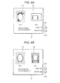
- Fig. 4 is a diagram showing sample displays of an
image display unit;
- Fig. 5 is a diagram showing sample printing of a
composite image; and
- Fig. 6 is a flowchart explaining processing
executed by a digital still camera according to another
embodiment.
-
DETAILED DESCRIPTION OF THE PREFERRED EMBODIMENTS
-
The preferred embodiments of a camera according to
the present invention will now be described in detail
hereinafter with reference to the accompanying drawings.
-
Fig. 1A is a front perspective view of an outline
showing an embodiment of a digital still camera 100 as an
example of an electronic camera to which the present
invention is applied, and Fig. 1B is a rear perspective
view thereof.
-
Referring to Fig. 1A, the digital still camera 100
has an imaging unit 24 for imaging an object, a fill light
unit 30 for emitting a' fill light toward the object, and an
optical finder 25 enabling a photographer to check a
picture composition including the object by looking into
it, at the front of the digital still camera. At the rear
thereof, it has an image display unit 8 for displaying a
photographed image, an information display unit 26 for
displaying a photographing setting status (so-called a
status LCD), and operation switches 21 for controlling
settings or switching of various functions including a NEXT
button 21c and a decision button 21d as selection means.
Furthermore, the digital still camera 100 has a release
switch 21a for a shutter release on the top face. The
respective components will be described later in detail
with a functional configuration. A flash light unit is of
a pop-up type and therefore it is not shown here. At the
bottom of the digital still camera 100, there is provided a
memory slot for use in mounting a memory card 9 (see Fig.
2) as a storing unit, though it is not shown in Figs. 1A
and 1B.
-
Referring to Fig. 2, there is shown a block
diagram of a functional configuration of the digital still
camera 100. In Fig. 2, the digital still camera 100
comprises an imaging unit 24 including a lens unit 1, which
is a photographing optical system, an aperture 2, and a
charge coupled device (CCD) 3, an imaging circuit 4, an A-D
converter 5, a memory 6, a D-A converter 7, an image
display unit 8 as a displaying means, a compandor '10, a
central processing unit (CPU) 11, a timing generator (TG)
12, an auto-exposure/auto-focus (AE/AF) processing circuit
13, a CCD driver 14, an aperture drive motor 15, an
aperture drive motor drive circuit 16, an optical system
drive motor 17, an optical system drive motor drive circuit
18, a battery 19, a flash memory 20 as a nonvolatile memory
unit, operation switches 21 including a zoom switch ST, a
flash light unit 22, a fill light unit 30 (which serves as
an AF fill light unit or a red-eye-reduction lamp), a
switching circuit 23, and an information display unit 26.
-
The imaging unit 24 comprises the lens unit 1 for
capturing an optical image of an object described later,
the aperture 2 for adjusting a light volume of a luminous
flux transmitted by the lens unit 1 and controlling an
exposure, and the CCD 3 for photoelectrically transferring
an optical image of the object focused on an optical path
of the lens unit 1, and it outputs a photoelectrically
converted image signal (an analog signal) to the imaging
circuit 4.
-
The imaging circuit 4 generates a predetermined
image signal by performing various image processes such as
sensitivity correction of the image signal input from the
CCD 3 in synchronization with a timing signal input from
the TG 12 and outputs the image signal to the A-D converter
5. The A-D converter 5 converts the input image signal
from the analog signal to a digital signal and outputs
image information to the memory 6 or the AE/AF processing
circuit 13 according to an instruction of the CPU 11.
-
The memory 6 comprises a buffer memory and
temporarily stores the input image signal. Upon receiving
an image display instruction from the CPU 11, the memory 6
outputs image information under the image display
instruction to the D-A converter 7. The D-A converter 7
converts the input image information to analog data and
outputs it to the image display unit 8 after processing the
data so as to adapt to the output display. On the other
hand, upon receiving an image storing instruction from the
CPU 11 when predetermined conditions described later are
met, the memory 6 outputs image information (for example,
in the JPEG format) under the image storing instruction to
the compandor 10. The compandor 10 then outputs the input
image information to the memory card 9.
-
The image display unit (also referred to as a
display unit) 8 comprises a thin film transistor (TFT) and
displays an image signal input from the D-A converter 7. A
content to be displayed is not always an image, but it can
be, for example, a text such as a menu for selecting
functions.
-
The memory card 9 is a memory comprising a
semiconductor memory and capable of storing data only once,
and it is a storage medium having image information storage
area for storing image information input from the compandor
10. It is assumed that the memory card 9 previously stores
unique ID information inside and has the ID information
printed or stamped on its surface.
-
Upon receiving an image readout instruction from
the CPU 11, the memory card 9 outputs image information
under the readout instruction to the compandor 10. The
compandor 10 then expands the input image information and
outputs it to the memory 6.
-
The compandor 10 comprises a compressor for
compressing image information input from the memory 6 in a
predetermined coding system and an expander for decoding
and expanding image information input from the memory card
9 for displaying the image information under the readout
instruction. In other words, the compandor 10 has a
function of a compressing means.
-
The CPU 11, which is an image processing means, an
imaging condition modification means, and a processing
condition modification means, reads out various application
programs related to photographing stored in the flash
memory 20 to a work area, which is not shown, executes
various processes including photographing based on a
program concerned, and displays a result of the processing
on the image display unit 8 or the information display unit
26.
-
The CPU 11 drives and controls the AE/AF
processing circuit 13 in response to half-pressing of the
release switch 21a (shown in Figs. 1A and 1B), determines
an exposure condition from an obtained photometric value,
drives the lens unit 1 to a focal position detected by an
AF process, and executes an exposure process in response to
full-pressing of the release switch 21a. It then performs.
image processing and digital conversion for the generated
image signal and temporarily stores it in the memory 6.
Thereafter, it compresses the image information by means of
the compandor 10 according to predetermined conditions and
outputs it to the memory card 9. The CPU 11 functions as a
storing unit for storing the image information obtained by
the imaging unit into a storage medium, a readout unit for
reading the ID information, and a storage control unit for
storing the ID information into the nonvolatile memory unit
when storing the image information into the storage medium.
-
The TG 12 generates a predetermined timing signal
and outputs it to the imaging circuit 4, the CPU 11, and
the CCD driver 14.
-
The AE/AF processing circuit 13 comprises an AE
processing circuit for executing an AE process for
detecting an appropriate exposure condition and an AF
processing circuit for executing an AF process for
detecting a focal position. The respective processes are
executed for image information input from the A-D converter
5 according to an instruction of the CPU 11.
-
In the AE process, the AE processing circuit makes
an arithmetic operation such as a cumulative addition for a
luminance value of a single input screen or of a
predetermined area within the screen. Based on a result of
the process, it calculates an appropriate exposure
condition at an actual exposure and outputs it to the CPU
11. On the other hand, in the AF process, the AF
processing circuit calculates an AF evaluation value of the
single input screen or of a predetermined area within the
screen and outputs a result of the calculation to the CPU
11.
-
The AF evaluation value has a characteristic of
increasing as the camera comes to a focus. In a graph
generated with the lens position as an axis of abscissas
and the AF evaluation value as an axis of ordinate, a
mountain is formed with a peak of a focal point. In other
words, the peak of the mountain or the focal point can be
obtained by comparing AF evaluation values with each other
obtained while moving the lens unit 1. This operation of
obtaining the AF evaluation value is referred to as a look-up
operation. The AF evaluation value is calculated by
analyzing frequencies of image information of a single
input screen or of a predetermined area within the screen.
In the frequency analysis, a bandpass filter is formed in
software to calculate an integral value of intensities of
image signals having passed through the bandpass filter,
and then a result of the calculation is considered an AF
evaluation value. In other words, the AF evaluation value
is contrast (a difference between light and dark)
information and is calculated by an arithmetic operation
for obtaining intensities of specific frequencies included
in the image.
-
The following describes the AF process with the
CPU 11 and the AF processing circuit. The CPU 11 drives
and controls the optical system drive motor drive circuit
18 as the driving means, to move a second lens group of the
lens unit 1 and generates image signals from the CCD 3
gradually in respective lens positions while moving the
second lens group. The AE/AF processing circuit 13
calculates an AF evaluation value for each image
information input from the A-D converter 5, detects a lens
position corresponding to the maximum AF evaluation value
as a focal point by comparing the AF evaluation values with
each other, and outputs it to the CPU 11.
-
Upon receiving an instruction from the CPU 11, the
CCD driver 14 drives and controls the CCD 3 in .
synchronization with timing signals input from the TG 12.
Specifically, it controls an electric charge storage time
of the CCD 3 according to an exposure adjustment control.
-
The aperture drive motor drive circuit 16 controls
a drive of the aperture drive motor according to an
instruction of the CPU 11 and the aperture drive motor 15
drives the aperture 2. The optical system drive motor
drive circuit 18 controls a drive of the optical system
drive motor 17 according to an instruction of the CPU 11
and a driving force of the optical system drive motor 17
drives the lens unit 1, by which the lens unit 1 moves to a
predetermined position.
-
The battery 19 is a power source for supplying a
power to the respective components of the digital still
camera 100 . For example, a lithium battery or an alkaline
battery is used.
-
The flash memory (an electrically erasable
programmable read-only memory (EEPROM) is also applicable)
20 stores various application programs and processing
programs related to imaging of the digital still camera 100
and further it is capable of storing the information
described later.
-
The operation switches 21 includes various kinds
of operation switches such as mode switches for switching
functions such as the release switch 21a, the NEXT button
21c, and the decision button 21d and a menu switch for
selecting settings. An operation of each switch causes a
signal to be generated and to be output to the CPU 11. The
release switch 21a is a two-stage switch comprising a half-press
release switch for starting the AE/AF process prior
to the photographing operation and a full-press release
switch for starting an actual exposure process. ,
-
The flash light unit 22 is provided to emit a
strobe light toward an object in case of insufficient
luminance of an ambient environment detected at
photographing. The switching circuit 23 controls the light
emission timing, the amount of emitted light, and the like.
-
Operations of the digital still camera 100
according to this embodiment will be described below with
reference to the accompanying drawings. Referring to Fig.
3, there is shown a flowchart of controlling the operations
of the digital still camera 100. Referring to Figs. 4A and
4B, there are shown sample displays of the image display
unit 8 of the digital still camera 100.
-
First, if a power switch (not shown) is set on in
step S101 in Fig. 3, the CPU 11 determines a mode in step
S102. In other words, if the CPU 11 determines that a
normal photographing mode is set according to a user's
operation of a mode setting button (not shown) among the
operation switches 21, it awaits an input of a depression
signal (S1 signal) of the release switch 21a in a first
stage in step S103. If the CPU 11 determines in this
condition that the depression signal (S1 signal) of the
release switch 21a in the first stage has been input, it
determines an exposure condition by performing the AE
process in step S104 and drives the lens unit 1 to the
focal position by performing the AF process, and further
awaits an input of a depression signal (S2 signal) of the
release switch 21a in a second stage in step S105. If the
CPU 11 determines that the depression signal (S2 signal) of
the release switch 21a in the second stage has been input,
it captures the image signal via the CCD 3 in step S107,
performs normal image processing in step S108 to obtain
image information, and stores the image information into
the memory card 9 on the basis of it in step S109.
Thereafter, the flow control returns to step S101.
-
On the other hand, if the CPU 11 determines that a
frame print mode is set according to a user's operation of
the mode setting button (not shown) in step S102, it awaits
a user's selection of a frame in step S110. More
specifically, the CPU 11 accesses the memory card 9, first,
reads out information on frame images previously stored
therein (including information on areas to be combined with
an object image (coordinates, etc.), while design
information can also be included), and displays two (one or
three or more is possible) frame images F1 and F2 and a
display prompting a user's selection on the image display
unit 8 as shown in Fig. 4A. In this condition, a frame is
displayed around the frame image F1, which is earlier in
the order of the two images to indicate that the frame
image F1 is a candidate for the selection.
-
If the user does not desire to combine the frame
image F1 with the image of the object to be photographed
then, depressing the NEXT button 21c causes the CPU 11 to
move the frame to around the next frame image F2, thereby
indicating that the frame image F2 is a candidate for the
selection. If the user does not desire to combine the
frame image F2 with the image of the object to be
photographed then, further depressing the NEXT button 21c
causes the CPU 11 to switch the screen of the image display
unit 8 so as to display other frame images F3 and F4.
Thereafter, a candidate for the frame image selection can
be displayed in the same procedure.
-
If a frame image F3, which is a candidate for the
selection, is selected as an image to be combined with the
image of the object to be photographed then as shown in
Fig. 4B, directly depressing the
decision button 21d causes
the
CPU 11 to determine that the frame image F3 is
selected. Thereafter, in step S111, the
CPU 11 determines
imaging conditions on the basis of the selected frame
image. More specifically, the
CPU 11 reads information on
the frame image F3 stored in the
memory card 9 and
determines the conditions as described below (modifies
default settings of the imaging conditions). Instead of
using all of the following conditions, a single condition
or combined conditions can be used.
- (1) A spot photometric system is adopted as a photometric
system. A photometry is performed mainly for a range where
the main object to be combined with the frame image is
supposed to exist (a central portion in the case'of the
frame image F3) and an exposure is adjusted to the portion,
thereby achieving an appropriate exposure of the main
object.
- (2) The photometric area is limited to the range where the
main object to be combined with the frame image is supposed
to exist (the central portion in the case of the frame
image F3). It is because an inappropriate exposure means
nothing to a background hidden by the frame image after the
composition. Furthermore, for example, if a figure is
combined as the main object and the frame image F3 is
selected, it is determined that the image to be combined
with the frame image F3 is likely to be an image of a full-length
figure. Therefore', a shape and a size of the
photometric area are determined so as to achieve an
appropriate exposure in the entire body of the figure. On
the other hand, if the frame image F2 is selected, it is
determined that the image to be combined with it is likely
to be an image of a half-length figure. Therefore, a shape
and a size of the photometric area are determined so as to
achieve an appropriate exposure in the upper body of the
figure.
- (3) Regarding an amount of exposure adjustment, an exposure
is adjusted by the amount enabling an optimum exposure in a
range where the main object to be combined with the frame
image is supposed to exist (the central portion in the case
of the frame image F3). For example, if a figure is
combined as the main object and the frame image F3 is
selected, it is determined that the image to be combined
with it is likely to be an image of a full-length figure.
Therefore, an amount of exposure adjustment is determined
so as to achieve an appropriate exposure in the entire body
of the figure. On the other hand, if the frame image F2 is
selected, it is determined that the image to be combined
with it is likely to be an image of a half-length figure.
Therefore, an amount of exposure adjustment is determined
so as to achieve an appropriate exposure in the upper body
of the figure. Particularly in photographing a figure, a
higher exposure is preferable.
- (4) Sensitivity of a camera sensitivity is modified
according to an object luminance in a range where the main
object to be combined with the frame image is supposed to
exist (the central portion in the case of the frame image
F3) . If the object luminance is low, the object image is
susceptible to image blur caused by a slow shutter speed.
If so, it is recommended to increase the camera
sensitivity. On the other hand, if the object luminance is
high, decreasing the camera sensitivity reduces noise.
- (5) An aperture precedence system is adopted. It is
because a part of the background around the main object to
be combined with the frame image is also combined therewith
in many cases and an unfocused background is preferable
since it is quiet in a composite image.
- (6) A flash light is frequently used. If the luminance of
the main object is low when it is to be combined with the
frame image, clear skin is achieved by using a flash light
frequently, for example, if the object is a figure.
Furthermore, preferably a red-eye-reduction function is
used at the light emission.
- (7) A ranging area is limited to a range where the main
object to be combined with the frame image is supposed to
exist (the central portion in the case of the frame image
F3). It is because unfocusing means nothing to a
background hidden by the frame image after the composition.
Furthermore, if a figure is combined as the main object and
the frame image F3 is selected, it is determined that the
image to be combined with the frame image F3 is likely to
be an image of a full-length figure. Therefore, a shape
and a size of the ranging area are determined so as to
achieve an appropriate focus in the entire body of the
figure. On the other hand, if the frame image F2 is
selected, it is determined that the image to be combined
with it is likely to be an image of a half-length figure.
Therefore, a shape and a size of the ranging area are
determined so as to achieve an appropriate focus in the
upper body of the figure.
- (8) A focus detection frequency is a frequency suitable for
a figure. If a figure is the main object to be combined
with a frame image, it is necessary to focus on the figure
rapidly and precisely. If the main object is a figure, an
outline of a face and positions of eyes, a nose, and a
mouth are fixed in general, and therefore a focusing
operation can be performed rapidly and precisely by using a
focus detection frequency according to them.
- (9) Image stabilization is performed. If a figure
(particularly a baby) is the main object to be combined
with a frame image, it is sometimes hard to take a photo
while he or she keeps still. If so, camera shake is
prevented by using an image stabilizer function (the lens
may be moved in the camera shake direction or a shutter
speed may be increased).
- (10) A specific scene mode is set. If a figure is the main
object to be combined with a frame image, for example, a
portrait photographing mode is set as a specific scene
mode, thereby achieving more appropriate imaging of the
main object existing 2 to 3 meters forward of the camera.
- (11) A specific field angle is set. If a figure is the
main object to be combined with a frame image, the field
angle is appropriately adjusted to the selected frame image
so that a full-length or half-length figure is imaged by
performing a trimming process.
- (12) A magnification of an image is adjusted. If a figure
is the main object to be combined with a frame image, the
magnification of the image is appropriately adjusted to the
selected frame image so that a full-length or half-length
figure is imaged by performing optical or electronic
zooming.
-
-
After determining the imaging conditions as
mentioned above, the CPU 11 awaits an input of a depression
signal (S1 signal) of the release switch 21a in the first
stage in step S112. If the CPU 11 determines that the
depression signal (S1 signal) of the release switch 21a in
the first stage has been input, it determines the exposure
condition by performing the AE process in step S113 and
drives the lens unit 1 to the focal position by performing
the AF process. It then awaits an input of a depression
signal (S2 signal) of the release switch 21a in the second
stage in step S114. If the CPU 11 determines that the
depression signal (S2 signal) of the release switch 21a in
the second stage has been input, it captures the image
signal via the CCD 3 under the imaging conditions
determined as mentioned above in step S116. It then
obtains image information by performing a normal image
process in step S117 and stores the image information with
being associated with the selected frame image information
into the memory card 9 on the basis of the obtained image
information in step S118. Thereafter, the flow control
returns to step S101. Note that the selected frame image
information can be incorporated into a header of the image
information.
-
A printer not shown can read the image information
and the selected frame image information, which have been
associated with each other and stored in the memory card 9,
combine it with previously stored image information of the
corresponding frame, and print the composite image.
Referring to Fig. 5, there is shown a composite image of
the frame image F3 and an object OBJ printed by the
printer. According to this embodiment, the digital still
camera 100 modifies the imaging conditions so as to match
the frame image F3 selected by a user before imaging,
thereby achieving a higher quality composite image. It is
also possible to combine the images in the digital still
camera 100.
-
The following describes another embodiment.
Referring to Fig. 6, there is shown a flowchart of another
control of an operation of the digital still camera 100.
In Fig. 6, the processes in steps S101 to S109 are the same
as in the embodiment shown in Fig. 3. Therefore, their
description is omitted here.
-
If the CPU 11 determines that the frame print mode
is set according to a user's operation of the mode setting
button (not shown) among the operation switches 21 in step
S102, it performs the above operation and awaits a user's
selection of a frame in step S210.
-
If the user desires to combine the frame image F3 ,
with an image of an object to be photographed then, his or
her depressing the
decision button 21d causes the
CPU 11 to
determine that the frame image F1 has been selected.
Thereafter, the
CPU 11 determines the image processing
conditions on the basis of the selected frame image in step
S211. More specifically, the
CPU 11 reads information on
the frame image F3 stored in the
memory card 9 and
determines the conditions as described below (modifies
default settings of the image processing conditions).
Instead of using all of the following conditions, a single
condition or combined conditions can be used.
- (1) Regarding an amount of exposure adjustment, an exposure
is adjusted by the amount enabling an optimum exposure in a
range where the main object to be combined with the frame
image is supposed to exist (a central portion in the case
of the frame image F3). For example, if a figure is
combined as the main object and the frame image F3 is
selected, it is determined that the image to be combined
with the frame image F3 is likely to be an image of a full-length
figure. Therefore, an amount of exposure adjustment
is determined so as to achieve an appropriate exposure in
the entire body of the figure. On the other hand, if the
frame image F2 is selected, it is determined that the image
to be combined with it is likely to be an image of a half-length
figure. Therefore, an amount of exposure adjustment
is determined so as to achieve an appropriate exposure in
the upper body of the figure. Particularly in
photographing a figure, a higher exposure is preferable.
- (2) A post photometric area (an exposure area after
imaging) is limited to a range where the main object to be
combined with the frame image is supposed to exist (the
central portion in the case of the frame image F3). It is
because an inappropriate exposure means nothing to a
background hidden by the frame image after the composition.
Furthermore, for example, if a figure is combined as the
main object and the frame image F3 is selected, it is
determined that the image to be combined with the frame
image F3 is likely to be an image of a full-length figure.
Therefore, a shape and a size of the photometric area are
determined so as to achieve an appropriate exposure in the
entire body of the figure. On the other hand, if the frame
image F2 is selected, it is determined that the image to be
combined with it is likely to be an image of a half-length
figure. Therefore, a shape and a size of the photometric
area are determined so as to achieve an appropriate
exposure in the upper body of the figure.
- (3) An amount of post auto white balance (RGB gain)
correction is determined so as to achieve an optimum skin
color on the assumption that the main object to be combined
with the frame image is a figure.
- (4) A post auto white balance area is limited to a range
where the main object to be combined with the frame image
is supposed to exist (the central portion in the case of
the frame image F3). It is because a difference from an
actual color means nothing to a background hidden by the
frame image after the composition. Furthermore, for
example, if a figure is combined as the main object and the
frame image F3 is selected, it is determined that the image
to be combined with the frame image F3 is likely to be an
image of a full-length figure. Therefore, a shape and a
size of the area are determined so as to achieve an
appropriate color appearance in the entire body of the
figure. On the other hand, if the frame image F2 is
selected, it is determined that the image to be combined
with it is likely to be an image of a half-length figure.
Therefore, a shape and a size of the area are determined so
as to achieve an appropriate color appearance in the upper
body of the figure.
- (5) An amount of gray level (y curve) correction is
determined so as to achieve sharpness of, for example, a
hair image on the assumption that the main object.to be
combined with the frame image is a figure.
- (6) An edge enhancement process is performed by adjusting
parameters of the edge enhancement process so as to achieve
an optimum edge feeling of skin on the assumption that the
main object to be combined with the frame image is a
figure.
- (7) Regarding a data compression ratio, a low compression
ratio is adopted so as to achieve clear skin of a human
being on the assumption that the main object to be combined
with the frame image is a figure.
- (8) A trimming process is performed. It is because a
background hidden by a frame image after composition is
unnecessary. For example, if a figure is combined as the
main object and the frame image F3 is selected, it is
determined that the image to be combined with the frame
image F3 is likely to be an image of a full-length figure.
Therefore, an image area other than the image of the full-length
figure is cut off and deleted by the trimming
process. On the other hand, if the frame image F2 is
selected, it is determined that the image to be combined
with it is likely to be an image of a half-length figure.
Therefore, an image area other than the image of the half-length
figure is cut off and deleted by the trimming
process. It can reduce a capacity of the image information
to be stored.
-
-
After determining the imaging conditions as
mentioned above, the CPU 11 awaits an input of a depression
signal (S1 signal) of the release switch 21a in the first
stage in step S212. If the CPU 11 determines that the
depression signal (S1 signal) of the release switch 21a in
the first stage has been input, it determines the exposure
condition by performing the AE process in step S213 and
drives the lens unit 1 to the focal position by performing
the AF process. The CPU 11 then awaits an input of a
depression signal (S2 signal) of the release switch 21a in
the second stage in step S214. If the CPU 11 determines
that the depression signal (S2 signal) of the release
switch 21a in the second stage has been input, it captures
the image signal via the CCD 3 in step S216. The CPU 11
then obtains image information under the imaging conditions
determined as mentioned above in step S217 and stores the
image information with being associated with the selected
frame image information into the memory card 9 on the basis
of the obtained image information in step S218.
Thereafter, the flow control returns to step S101.
According to this embodiment, the digital still camera 100
modifies the imaging conditions so as to match the frame
image F3 selected by a user before performing the image
data processing for the image information obtained by image
pickup, thereby achieving a higher-quality composite image.
-
While the present invention has been described in
connection with certain preferred embodiments, it is to be
understood that the subject matter encompassed by the
.present invention is not limited to those specific
embodiments and that appropriate changes and modifications
may be made-in the invention. For example, if the
information on the frame image is modified to include
information for specifying a color or a pattern of the
frame image, or, for example, if the entire frame image is
bluish, more balanced printing is achieved by giving a
tincture of blue in imaging or image data processing of the
object image. The frame image information can be
previously stored in the memory 6, which is a storage unit.
-
According to the present invention, it becomes
possible to provide an electronic camera enabling.printing
of a higher-quality composite image.