BACKGROUND OF THE INVENTION
Field of the Invention
The present invention relates to a soft magnetic member
exhibiting high complex permeability in a high frequency band
exceeding 800 MHz and a method of manufacturing the soft
magnetic member. Also the present invention relates to an
electromagnetic wave controlling sheet advantageously used
in information and communications equipment.
Description of the Related Art
Information and communications equipment tends to become
smaller in size and the frequency band of radio waves used
is shifting to the high frequency side. So far, high
performance design of electronic parts utilizing permittivity
has been carried out. On the other hand, in a case where
efficiency is to be improved by utilizing electromagnetic waves
in near-field,high performance design utilizing permeability
can be expected. Because the permeability of magnetic
materials in a high frequency band equal to 800 MHz or more
shows much smaller values than the permeability in a band of
lower frequency, permeability has not hitherto been utilized
in a positive manner and dielectrics have been exclusively
used in high frequency related parts. However, in high
frequency related parts including antennas, limitations to
the improvement of properties by using permittivity have
appeared and it is difficult to expect dramatic improvements
in efficiency.
On the other hand, research to improve permeability in
high frequencies such as a giga Herz band (hereinafter referred
to as a "GHz band") is also being pushed forward with.
For example, it is known that a multilayer film having
a structure formed by alternately depositing a magnetic
material layer and a nonmagnetic material layer (SiO2) on a
substrate by the ion beam sputtering shows excellent complex
permeability in a GHz band (NTT R&D, Vol. 42, No. 5 (1993),
pp. 689-696). In this case, in order to realize high
permeability, the smaller magnetostriction, the more
advantageous. For this reason, there has been proposed, for
example, a magnetic material layer in which magnetostriction
is controlled to low levels by causing Fe (magnetostriction:
negative) and an NiFe alloy (magnetostriction: positive) to
diffuse mutually. Also, a film of small magnetostriction,
such as a CoNbZr film, is subjected to a heat treatment in
a magnetic field, thereby imparting induction anisotropy to
the film, so that high permeability is maintained even in a
GHz band. Incidentally, anisotropy can be imparted also by
forming a fine pattern in addition to performing a heat
treatment in a magnetic field (the Journal of Japan Society
for Applied Magnetics, Vol. 24 (2000), pp. 731-734).
In the above-described techniques for increasing
permeability in a GHz band involve increasing an anisotropic
magnetic field thereby shifting to a higher frequency side
by depositing a soft magnetic film on a substrate and thereafter
imparting induction anisotropy to the soft magnetic film by
subjecting the film to a heat treatment in a magnetic field
or imparting shape anisotropy by forming a fine pattern.
However, in the above-described techniques, it is necessary
to use a hard substrate material and furthermore in order to
impart anisotropy, it is necessary to perform an expensive
heat treatment and work. Therefore, shape and price
restrictions are severe and form a bottleneck in practical
application.
The present invention was made on the basis of such
technical problems and aims to achieve high permeability in
a high frequency band exceeding 800 MHz without the treatment
of imparting induction anisotropy by performing a heat
treatment in a magnetic field or without the treatment of
imparting shape anisotropy by forming a fine pattern and
furthermore aims to provide a soft magnetic member which does
not require the use of a hard substrate material.
SUMMARY OF THE INVENTION
The present invention provides a multilayer soft magnetic
member including a soft magnetic metal layer and in which a
magnetic coupling between the soft magnetic metal layer and
other layers is improved. In the present invention, the first
through to the third techniques which will be described below
are proposed as techniques for improving a magnetic coupling
between the soft magnetic metal layer and other layers.
More specifically, in the first technique, there are
provided an insulating layer, a metal sublayer disposed
opposite to the insulating layer, and a soft magnetic metal
layer disposed on the metal sublayer, and a region having a
higher saturation flux density than other regions is formed
in the soft magnetic metal layer on the side of said metal
sublayer (hereinafter may sometimes be referred to as a "region
of high saturation flux density"). By providing such a region
of high saturation flux density on the side of the metal sublayer,
it is possible to strengthen a magnetic coupling between the
soft magnetic metal layer and the metal sublayer.
Therefore, when the metal sublayer is constituted by a
material having a larger anisotropic magnetic field than the
soft magnetic metal, it is possible to enlarge the anisotropic
magnetic field of the soft magnetic metal layer.
Because a resonance frequency has a relation which is
proportional to the square root of an anisotropic magnetic
field, by adopting the construction of the present invention
it is possible to achieve high permeability in a high frequency
band exceeding 800 MHz, and further in a GHz band. In order
to enjoy this effect, it is desirable that other regions of
the soft magnetic metal layer of the present invention be
constituted by a material having higher permeability than the
region of high saturation flux density.
In the soft magnetic member of the invention, it is
preferred that the metal sublayer be a material having a higher
coercive force than the soft magnetic metal layer.
In the soft magnetic member of the present invention,
a unit comprising the insulating layer, the metal sublayer
and the soft magnetic metal layer can be used singly. Or a
plurality of such units can also be used by being laminated
in multiple layers.
In the soft magnetic member of the present invention,
a metal oxide layer may be interposed between the insulating
layer and the metal sublayer.
Incidentally, there is an alloy including Fe as a typical
exampleofasoftmagneticmetal. In this alloy, its saturation
flux density varies according to the Fe concentration.
Concretely, the higher the Fe concentration, the higher the
saturation flux density. If the soft magnetic metal layer
is constituted by an Fe-Ni alloy of a predetermined composition,
then by providing an alloy region having a higher Fe
concentration than the predetermined composition between the
soft magnetic metal layer and the metal sublayer, it is possible
to improve a magnetic coupling between the soft magnetic metal
layer and the metal sublayer, because this region has a higher
saturation flux density than the Fe-Ni alloy region of the
predetermined composition.
Hence, in the second technique, there are provided a first
region constituted by a resin material, a second region which
is disposed opposite to the first region and constituted by
an alloy containing Fe and manifesting soft magnetism, and
a third region disposed between the first region and the second
region and constituted by a metal having a larger anisotropic
magnetic field than the second region. And at the same time,
between the second region and the third region is further
provided a fourth region having a higher Fe concentration than
the second region. Because in the second technique a fourth
region having a higher Fe concentration than the second region
is provided between the second region and the third region,
it is possible to increase a magnetic coupling between the
fourth region and the third region. As a result of this, a
magnetic coupling between the third region and the second
region corresponding to the soft magnetic metal layer is also
improved.
In the soft magnetic member of the present invention,
the first region is constitutedby a resin material. Therefore,
the soft magnetic member of the present invention has
flexibility and is easily handled when it is installed in
various types of equipment.
In the invention, the second region and the fourth region
can be constituted by an alloy containing Ni and/or Co, and
Fe. That is, the present invention includes a case where the
fourth region exhibits soft magnetism. Even in this case,
a higher Fe concentration in the fourth region than the second
region is a precondition.
Although as described above, the second region and the
fourth region can be constituted by an alloy containing Ni
and/or Co, and Fe, the second region and the fourth region
can also be constituted by an alloy having the same component
elements. For example, when the second region and the fourth
region are to be formed by electrolytic plating, by using the
same plating bath and controlling plating conditions, it is
possible to form the fourth region having a higher Fe
concentration than the second region. At this time, the second
region and the fourth region are constituted by an alloy having
the same component elements. As described above, according
to the present invention, it is possible to form the second
region and the fourth region constituted by an alloy having
the same component elements by performing electrolytic plating
once. However, it is needless to say that the second region
and the fourth region may be constituted by metals (alloys)
having different component elements.
As will be described later, it is possible to ensure a
mode in which the Fe concentration in the fourth region
increases continuously toward the third region. By adopting
this embodiment, the frequency properties of complex
permeability can be controlled by controlling the value of
an anisotropic magnetic field. Furthermore, corrosion
resistance can be improved because the Fe concentration of
the surface of a soft magnetic metal layer decreases
relatively.
When in the soft magnetic member of the invention, an
alloy containing Ni and/or Co, and Fe is adopted in the second
region and the fourth region, the third region may be
constituted by Ni or an Ni based alloy of a predetermined
composition.
In the soft magnetic member of the present invention,
a unit comprising the first region, the second region, the
third region and the fourth region may be used singly or this
unit may be used by being laminated in multiple layers.
In the third technique, by keeping the ratio between the
thickness s of the metal sublayer and the thickness p of the
soft magnetic metal layer (p/s) within a certain range, a
magnetic coupling between the soft magnetic metal layer and
the metal sublayer is increased. That is, in the present
invention there is provided a soft magnetic member comprising
an insulating layer, a metal sublayer disposed opposite to
the insulating layer, and a soft magnetic metal layer disposed
on the metal sublayer, and it is proposed that 5 ≤ p/s < 10
and 0 < s < 100 nm.
Also in this case, it is preferred that the metal sublayer
be constituted by a material having a higher coercive force
or a larger anisotropic magnetic field than soft magnetic metal
layer.
In the soft magnetic member of the present invention,
it is preferred that the soft magnetic metal layer be
constituted by an alloy containing 20 to 80 wt % Fe, and Ni
and/or Co.
Furthermore, the soft magnetic member of the present
invention includes an embodiment in which a unit comprising
an insulating layer, a metal sublayer and a soft magnetic metal
layer is laminated in multiple layers.
Incidentally, it is also possible to use the third
technique and the first technique in combination, whereby it
is ensured that in the soft magnetic metal layer, on the side
of the metal sublayer, there is formed a region having a higher
saturation flux density than other regions, and it can be
ensured that providing that the thickness of the metal sublayer
is denoted by s and the thickness of the soft magnetic metal
layer is denoted by p, then the relationships hold: 5 ≤ p/s
≤ 10 and 0 < s ≤ 100 nm.
The soft magnetic member of the present invention was
described in detail above. By being installed in the interior
of a cellular phone, for example, the soft magnetic member
of the invention can contribute to an improvement of radiation
efficiency of electromagnetic waves emitted to outside the
cellular phone by its antenna. Therefore, the soft magnetic
member of the present invention can be used as an
electromagnetic wave controlling sheet. And this
electromagnetic wave controlling sheet comprises a substrate
having flexibility, a conductive metal layer supported by the
substrate, and a soft magnetic metal layer which is supported
by the conductive metal layer and comprises an Fe-Ni based
alloy. In this electromagnetic wave controlling sheet,
between the conductive metal layer and the soft magnetic metal
layer is interposed a compound which improves a magnetic
coupling between the conductive metal layer and the soft
magnetic metal layer. The substrate has a thickness of 25
µm or less, the conductive metal layer has a thickness of 100
nm or less, and the soft magnetic metal layer has a thickness
of 1 µm or less.
In the electromagnetic wave controlling sheet of the
present invention, for example, Ni can be used in the conductive
metal layer.
It is preferred that PET (polyethylene terephtalate) or
PBT (polybutylene terephtalate) be used as the substrate.
The soft magnetic metal member of the present invention,
in which a magnetic coupling between the soft magnet metal
layer and other layers is improved, can be advantageously
manufactured by the following manufacturing method. More
specifically, the soft magnetic metal member of the present
invention can be manufactured by a manufacturing method, which
comprises a step (a) for forming a conductive metal film on
a resin film and a step (b) for forming a soft magnetic metal
film containing Fe on the conductive metal film by electrolytic
plating. In the step (b), a region is formed on the side of
an interface with said conductive metal film in the soft
magnetic metal film, and the Fe concentration of the region
is higher than the average Fe concentration of the soft magnetic
metal film.
In this step (b), by performing electrolytic plating under
conditions set so that the Fe concentration of the soft magnetic
metal film decreases continuously with increasing distance
from the interface with the conductive metal film, it is
possible to form a region having higher Fe concentration than
the average Fe concentration of the soft magnetic metal film
on the side of an interface with the conductive metal film
in the soft magnetic metal film. For example, this can be
accomplished by performing electrolytic plating under such
conditions that the stirring conditions during electrolytic
plating are continuously changed or the current density is
continuously changed.
Soft magnetic members which can be advantageously used
in a high frequency band exceeding 800 MHz were described above.
The soft magnetic member of the present invention can also
be used in a frequency band of 800 MHz or lower, for example,
in the vicinity of 100 MHz. In this case, it is necessary
only that if the thickness of the metal sublayer is denoted
by s and the thickness of the soft magnetic metal layer is
denoted by p, then the relationships hold: 4 ≤ p/s ≤ 15 and
100 < s ≤ 1000 nm.
BRIEF DESCRIPTION OF THE DRAWINGS
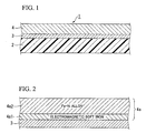
FIG. 1 is a partial sectional view showing a soft magnetic
member in an embodiment of the present invention;
FIG. 2 is a partial sectional view showing an example
of the construction of a soft magnetic metal layer which
constitutes the soft magnetic member shown in FIG. 1;
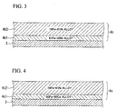
FIG. 3 is a partial sectional view showing another example
of the construction of a soft magnetic metal layer which
constitutes the soft magnetic member shown in FIG. 1;
FIG. 4 is a partial sectional view showing another example
of the construction of a soft magnetic metal layer which
constitutes the soft magnetic member shown in FIG. 1;
FIG. 5 is a graph showing the distance from the interface
between a soft magnetic metal layer and a metal sublayer and
the Fe concentration in the soft magnetic metal layer;
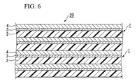
FIG. 6 a partial sectional view showing the construction
of a laminated soft magnetic member obtained by laminating
the soft material member shown in FIG. 1 in multiple layers;
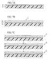
FIG. 7A to FIG. 7C are each a view showing a method of
manufacturing the laminated soft magnetic member shown in FIG.
6; FIG. 7A is a view showing a condition in which a metal sublayer
is formed on a resin film; FIG. 7B is a view showing a condition
in which a soft magnetic metal layer is formed on a metal
sublayer; FIG. 7C is a view showing how a soft magnetic member
is laminated, with a resin film and a soft magnetic metal layer
opposed to each other;
FIG. 8A to FIG. 8E are each a view showing another method
of manufacturing the laminated soft magnetic member shown in
FIG. 6; FIG. 8A is a view showing a condition in which a metal
sublayer is formed on a resin film; FIG. 8B is a view showing
a condition in which a soft magnetic metal layer is formed
on a metal sublayer; FIG. 8C is a view showing a condition
in which a resin layer is formed on a soft magnetic metal layer;
FIG. 8D is a view showing a soft magnetic member in which a
metal sublayer, a soft magnetic metal layer and a resin layer
are laminated; FIG. 8E is a view showing how a soft magnetic
member is laminated, with a resin layer and a metal sublayer
opposed to each other;
FIG. 9 is a graph showing the relationship between the
distance of an Fe-Ni alloy from the interface with a metal
sublayer and Fe concentration in soft magnetic members produced
under the conditions a to c in Example 1;
FIG. 10 is a graph showing the frequency properties of
an imaginary part (µ") of the complex permeability of soft
magneticmembers produced under the conditions a to c in Example
1;
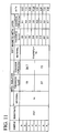
FIG. 11 is a table showing the construction of the samples
a to h obtained in Example 2;
FIG. 12 is a graph showing the measurement result of the
complex permeability of the sample a in Example 2;
FIG. 13 is a graph showing the measurement result of the
complex permeability of the sample b in Example 2;
FIG. 14 is a graph showing the measurement result of the
complex permeability of the sample c in Example 2;
FIG. 15 is a graph showing the measurement result of the
complex permeability of the sample d in Example 2;
FIG. 16 is a graph showing the measurement result of the
complex permeability of the sample e in Example 2;
FIG. 17 is a graph showing the measurement result of the
complex permeability of the sample f in Example 2;
FIG. 18 is a graph showing the measurement result of the
complex permeability of the sample g in Example 2;
FIG. 19 is a graph showing the measurement result of the
complex permeability of the sample h in Example 2;
FIG. 20 is a graph showing the B-H curve of the sample
a in Example 2;
FIG. 21 is a graph showing the B-H curve of the sample
b in Example 2;
FIG. 22 is a graph showing the B-H curve of the sample
c in Example 2;
FIG. 23 is a graph showing the B-H curve of the sample
d in Example 2;
FIG. 24 is a graph showing the B-H curve of the sample
e in Example 2;
FIG. 25 is a graph showing the B-H curve of the sample
g in Example 2;
FIG. 26 is a graph showing the B-H curve of a sample
deposited a 19 nm thick Ni film; and
FIG. 27 is a graph showing the B-H curve of a sample
deposited a 37 nm thick Ni film.
DETAILED DESCRIPTION OF THE PREFERRED EMBODIMENTS
Embodiments of the present invention will be described
below.
FIG. 1 is a partial sectional view showing a soft magnetic
member in an embodiment of the present invention.
A soft magnetic member (an electromagnetic wave
controlling sheet) 1 shown in FIG. 1 is constituted by a resin
film 2, a metal sublayer 3 formed on the resin film 2 and a
soft magnetic metal layer 4 formed on the metal sublayer 3.
FIG. 2 to FIG. 5 are each a partial sectional view showing
examples of construction of a soft magnetic metal layer
constituting the soft magnetic member.
As the resin film 2 which functions as an insulating layer,
Polyethylene, polypropylene, polystyrene, melamine resin,
urea resin, phenol resin, polyethylene terephthalate,
polybutylene terephthalate, polysulfone, polycarbonate,
polytetrafluorethylene, polyamide-imide, polyamide,
polyolefin, polyimide, PPS (polyphenylenesulfide),
fluoroplastics and silicone resin can be used. Among these,
it is desirable to use resin materials having heat resistance
when a heat treatment is performed in the manufacturing process
of a laminated soft magnetic member, as will be described later.
The soft magnetic metal layer 4 can be constituted by
any of the transition metal elements exhibiting soft magnetism
or any of the alloys of transition metal elements and other
metal elements. As concrete examples, such alloys are those
which contain, as a main component, at least one element
selected from the group consisting of Fe, Ni and Co, and they
are Fe-Ni based alloys, Fe-Co based alloys, Fe-Ni-Co based
alloys and Co-Ni based alloys. Among these alloys, it is
desirable to use alloys having a saturation flux density of
1.0 T or greater and, preferably, of 1.5 T or greater. Among
these, it is especially desirable to use Fe-Ni based alloys,
Fe-Co based alloys and Fe-Ni-Co based alloys having an Fe
content of 20 to 80 wt % (preferably, 30 to 70 wt %, more
preferably, 40 to 65 wt %). Alloys having such a composition
are high in saturation flux density, and are advantageous in
that the resonance frequency is shifted to the higher frequency
side by increasing the anisotropic magnetic field through
anisotropy control. These alloys can contain 15 at% or less
of one or more of Nb, Mo, Ta, W, Zr, Mn, Ti, Cr, Cu and Co.
Incidentally, when a soft magnetic metal layer 4 is formed
by plating (electrolytic plating or non-electrolytic plating),
such elements as C and S are inevitably contained, and the
soft magnetic metal layer 4 of the present invention allows
the presence of such elements contained.
As for the soft magnetic metal layer 4, either a
crystalline alloy or an amorphous alloy can be used. As an
amorphous alloy, Co based alloys and Fe based alloys can be
used. Additionally, the present invention allows the use of
Fe based microcrystalline alloys. A microcrystalline alloy
is generally known as an alloy which is mainly composed of
fine crystals of about 10 nm in grain size.
The soft magnetic metal layer 4 can be produced by a variety
of film formation processes including the plating, vacuum
evaporation method, sputtering and the like. These film
formation processes can be applied each alone. Accordingly,
the soft magnetic metal layer 4 can be formed either solely
by plating or solely by evaporation. Needless to say, a
plurality of film formation processes can be combined.
Plating is preferable for the present invention in that plating
can form films at lower temperatures than the vacuum
evaporation method. This is because in the present invention,
the soft magnetic metal layer 4 is formed on a resin film 2,
and hence it is preferable that no thermal effect is given
to the resin film 2. Additionally, plating has a merit that
plating can obtain a prescribed thickness of film in a shorter
period of time as compared to the sputtering method.
Incidentally, when the soft magnetic metal layer 4 is obtained
by plating, some elements such as S contained in the plating
bath are mixed in the soft magnetic metal layer 4, and hence
the soft magnetic metal layer 4 formed by plating is
discriminable from the soft magnetic metal layers 4 formed
by the other processes.
For the metal sublayer 3, it is desirable to select a
material having a higher coercive force (anisotropic magnetic
field) than the soft magnetic metal layer 4. By doing so,
it is possible to increase the anisotropic magnetic field of
the soft magnetic metal layer 4, thereby to increase the
ferromagnetic resonance frequency in a GHz band. As a result,
it is possible to increase the µ' (real part of complex
permeability) in the vicinity of 2 GHz and simultaneously to
reduce µ" (imaginary part of complex permeability). In the
frequency bands used in portable communications equipment,
the larger µ' and the smaller µ" , the higher an effect on the
radiation efficiency improvement of electromagnetic waves
will be. Incidentally, an effect on the permeability
improvement in a GHz band can also be expected by forming a
layer composed of a material similar to that of the metal
sublayer 3 on the soft magnetic metal layer 4. When the soft
magnetic metal layer 4 is an Fe-Ni alloy, it is desirable to
use Ni as the metal sublayer 3.
Although the metal sublayer 3 serves to enhance the
anisotropic magnetic field of the soft magnetic metal layer
4, the metal sublayer 3 also plays a role of a conductive layer
becoming necessary when the soft magnetic metal layer 4 is
formed by electrolytic plating on the resin film 2. The metal
sublayer 3 can be formed, for example, by the vacuum evaporation
method, the sputtering or non-electrolytic plating.
Next, the thickness of the soft magnetic member 1 will
be described.
The thickness of the resin film 2 should be 50 µm or less.
Although the resin film 2 functions as a substrate of the soft
magnetic member 1, the resin film 2 also carries out the function
of mutual insulation of the soft magnetic metal layers 4 when
the soft magnetic member 1 is laminated. However, if this
insulating layer becomes thick, the packing density of the
soft magnetic metal layer 4 decreases and hence the
permeability of the soft magnetic member 1 decreases.
Therefore, the thickness of the resin film 2 should be 50 µm
or less. The preferable thickness of the resin film 2 is 25
µm or less and the more preferable thickness of the resin film
2 is 10 µm or less. As a matter of course, it is difficult
to manufacture an extremely thin resin film 2 and, at the same
time, it is impossible for an extremely thin resin film 2 to
have a predetermined strength necessary for forming the soft
magnetic metal layer 4. Therefore, it is recommended that
the thickness be 0. 2 µm or more, or 2 µm or more. Incidentally,
because the resin film 2 used in the present invention has
flexibility, handling is easy when the soft magnetic member
1 including this resin film 2 is installed in various types
of equipment.
It is preferred that the soft magnetic metal layer 4 be
1 µm or less in thickness. Incidentally, the thickness of
the soft magnetic metal layer 4 is hereinafter denoted by p.
This is because in thicknesses with p exceeding 1 µm, eddy
current losses are large in a high frequency band exceeding
800 MHz which is a target of the present invention and hence
the function as a magnetic material deteriorates. Therefore,
the thickness p is more preferably 0.5 µm or less. Because
it is desirable that the soft magnetic metal layer 4 be densely
formed, it is necessary that the soft magnetic metal layer
4 has a minimum film thickness of such an extent that enables
a dense film to be formed by various processes. Incidentally,
an oxide film may be formed on the surface of the soft magnetic
metal layer 4.
In order to ensure that the metal sublayer 3 functions
to improve the anisotropic magnetic field of the soft magnetic
metal layer 4 and also functions as a conductive layer during
electrolytic plating, the thickness of the metal sublayer 3
should be 100 nm or less when the metal sublayer 3 is used
in a high frequency band exceeding 800 MHz. Incidentally,
the thickness of the metal sublayer 3 is hereinafter denoted
by s. A preferable film thickness s for a use in a high frequency
band exceeding 800 MHz is 80 nm or less, and a more preferable
film thickness s is 50 nm or less.
Incidentally, between the metal sublayer 3 and the resin
film 2, for example, a metal oxide layer or an adhesive layer
may be interposed. Also, on the surface of the metal sublayer
3, i.e., between the metal sublayer 3 and the soft magnetic
metal layer 4, a metal oxide layer may be present. The
interposition of a metal oxide layer which is large in electric
resistance weakens the magnetic coupling between the metal
sublayer 3 and the soft magnetic metal layer 4 a little, but
increases the electric resistance along the film cross section
direction and provides an effect which reduces the eddy current.
If the thickness of the metal oxide layer is too large, plating
becomes difficult. Therefore, the thickness of the metal
oxide layer should be 40 nm or less and is preferably 20 nm
or less, more preferably 10 nm or less.
This metal oxide layer can be formed by exposing the metal
sublayer 3 to the air after completion of the metal sublayer
3 formation. This is also the case for the oxide film formed
on the surface of the soft magnetic metal layer 4.
The soft magnetic member 1 of the present invention is
characterized by that a region rich in Fe (an Fe-rich region)
is provided on the side of the metal sublayer 3 of the soft
magnetic metal layer 4.
FIG. 2 shows an example of the construction of a soft
magnetic metal layer 4a. The soft magnetic metal layer 4a
shown in FIG. 2 is constituted by an electromagnetic soft iron
layer 4a1 and an Fe-Ni alloy layer 4a2 and the electromagnetic
soft iron layer 4a1 is disposed on the side of the metal sublayer
3. Because the electromagnetic soft iron layer 4a1 has a higher
Fe concentration than the Fe-Ni alloy layer 4a2, it follows
that in the soft magnetic metal layer 4a shown in FIG. 2, an
Fe-rich region is provided on the side facing the metal sublayer
3. Furthermore, because electromagnetic soft iron
(saturation flux density: 2 T, permeability: 200) has a higher
saturation flux density than an Fe-Ni alloy (for example, in
the case of a composition of a 19 wt % Fe-81 wt % Ni alloy,
saturation flux density: 1 T, permeability: 2500), in the soft
magnetic metal layer 4a shown in FIG. 2, a region having a
higher saturation flux density than other regions is provided
on the side facing the metal sublayer 3.
In the present invention, an Fe-rich region, i.e., a region
having a higher saturation flux density than other regions
is provided on the side facing the metal sublayer 3. As a
result of this, for example, when the metal sublayer 3 is
constituted by Ni of large anisotropic magnetic field, the
magnetic coupling between the metal sublayer 3 and the soft
magnetic metal layer 4 (4a) becomes strong and it becomes
possible to control µ' in a wider band or peak values of µ"
in higher frequencies.
FIG. 3 shows another example of the construction of a
soft magnetic metal layer 4b. The soft magnetic metal layer
4b shown in FIG. 3 is constituted by a 61 wt % Fe-39 wt % Ni
alloy layer 4b1 and a 19 wt % Fe-81 wt % Ni alloy layer 4b2,
both soft magnetic metal layers having the same component
elements, and the 61 wt % Fe-39 Ni wt % alloy layer 4b1 is
provided on the side of the metal sublayer 3. Because the
61 wt % Fe-39 wt % Ni alloy has a higher Fe content than the
19 wt % Fe-81 wt % Ni alloy, it follows that also in the soft
magnetic metal layer 4b shown in FIG. 3, an Fe-rich region
is provided on the side facing the metal sublayer 3. Also,
the 61 wt % Fe-39 wt % Ni alloy (saturation flux density: 1.6
T, permeability: 1500) has a higher saturation flux density
than the 19 wt % Fe-81 wt % Ni alloy (saturation flux density:
1 T, permeability: 2500) , it follows that in the soft magnetic
metal layer 4b shown in FIG. 3, a region having a higher
saturation flux density than other regions is provided on the
side facing the metal sublayer 3.
FIG. 4 shows another example of the construction of a
soft magnetic metal layer 4c. The soft magnetic metal layer
4c is constituted by a 50 wt % Fe-50 Co wt % alloy (what is
called Permendur) layer 4c1 and a 19 wt % Fe-81 Ni wt % alloy
layer 4c2, and the 50 wt % Fe-50 wt % Co wt % alloy layer 4c1
is provided on the side of the metal sublayer 3. Because the
50 wt % Fe-50 wt % Co wt % alloy layer 4c1 has a higher Fe
content than the 19 wt % Fe-81 wt % Ni alloy layer 4c2, it
follows that also in the soft magnetic metal layer 4c shown
in FIG. 4, an Fe-rich region is provided on the side facing
the metal sublayer 3. Also, the 50 wt % Fe-50 wt % Co alloy
(saturation flux density: 2.4 T, permeability: 1000) has a
higher saturation flux density than the 19 wt % Fe-81 wt %
Ni alloy (saturation flux density: 1 T, permeability: 2500),
in the soft magnetic metal layer 4c shown in FIG. 4, a region
having a higher saturation flux density than other regions
is provided on the side facing the metal sublayer 3.
FIG. 5 is a drawing showing another example of the
construction of the soft magnetic metal layer 4 and a graph
showing the distance from the interface between the soft
magnetic metal layer 4 and the metal sublayer 3 and the Fe
concentration in the soft magnetic metal layer 4. In the
examples shown in FIG. 2 to FIG. 4, the soft magnetic metal
layers 4a, 4b, 4c are each constituted by two metal (alloy)
layer having different compositions. However, in the example
shown in FIG. 5, a soft magnetic layer 4d is constituted by
a basically single soft magnetic alloy and an Fe-rich region
is formed in this layer. Incidentally, FIG. 5 is a graph in
which the distance from the interface between the soft magnetic
metal layer 4d and the metal sublayer 3 is plotted on the abscissa
and the Fe concentration in the soft magnetic metal layer 4d
is plotted on the ordinate.
In FIG. 5, the thick solid line indicates the average
concentration of Fe. In FIG. 5, the thin solid line (d1)
indicates the Fe concentration in the soft magnetic metal layer
4d. As shown in FIG. 5, in the soft magnetic metal layer 4d
the Fe concentration is highest at the interface with the metal
sublayer 3 and decreases continuously with increasing distance
from this interface. Therefore, it follows that also in the
soft magnetic metal layer 4d, an Fe-rich region is provided
on the side facing the metal sublayer 3. In the Fe-Ni alloy,
in which the higher the Fe concentration, the higher the
saturation flux density, a region having a higher saturation
flux density than other regions is provided on the side facing
the metal sublayer 3. Incidentally, as indicated by the
alternate long and short dash line (d2), the Fe concentration
maybe such that the Fe concentration is highest at the interface
with the metal sublayer 3 and decreases continuously with
increasing distance from this interface, but it becomes almost
constant from a certain position. Furthermore, as indicated
by the dotted line (d3) of FIG. 5, the Fe concentration may
be such that the Fe concentration shows an almost constant
value from the interface with the metal sublayer 3 to a
predetermined position and follows by a constant value a little
lower than the above-described almost constant value after
this predetermined position.
As described above, the present invention includes a mode
in which the Fe concentration changes intermittently
(hereinafter sometimes referred to as "a first mode") and a
embodiment in which the Fe concentration changes continuously
(hereinafter sometimes referred to as "a second mode").
When the first mode adopted, by using combinations of
various metals and alloys, such as a combination of an Fe-Ni
alloy and an Fe-Co alloy and a combination of an Fe-Ni alloy
and an Fe-Ni-Co alloy as in the above-described soft magnetic
metal layers 4a, 4b, 4c, it is possible to provide a region
rich in Fe (an Fe-rich region) on the side of the metal sublayer
3 of the soft magnetic metal layer 4.
When the second mode is adopted, by using the substantially
same alloy as in the soft magnetic metal layer 4d, it is possible
to provide a region rich in Fe (an Fe-rich region) on the side
of the metal sublayer 3 of the soft magnetic metal layer 4.
Furthermore, as a third mode, by keeping the ratio between
the thickness s of the metal sublayer and the thickness p of
the soft magnetic metal layer 4 (p/s) with a certain range,
it is also possible to increase a magnetic coupling between
the soft magnetic metal layer and the metal sublayer. When
this mode is adopted, "p/s" should be in the range of 5 ≤ p/s
< 10.
The thickness s of the metal sublayer 3 and the thickness
p of the soft magnetic metal layer 4 were described above,
respectively. By keeping the ratio between s and p (p/s) in
the range recommended by the present invention, it is possible
to increase a magnetic coupling between the soft magnetic metal
layer 4 and the metal sublayer 3. More specifically, if p/s
is too small, the frequency properties of the imaginary part
of complex permeability (µ") becomes broad or shows double
peak and tan δ (= µ"/µ', µ': the real part of complex
permeability) becomes large. This is undesirable. On the
other hand, if p/s is too large, the frequency properties of
µ" shows a single peak and the band also becomes narrow.
However, the frequency at which µ' begins to attenuate
decreases and the permeability in a GHz band deteriorates.
Although p/s depends on the thickness and material quality
of the soft magnetic metal layer 4 and metal sublayer 3, the
range of p/s should be 5 ≤ p/s < 10 and is preferably 6 ≤ p/s
< 8.
The first mode, the second mode and the third mode were
described in detail above. Needless to say, it is possible
to use the first mode and the third mode in combination and
the second mode and the third mode in combination.
In the soft magnetic member 1 shown in FIG. 1, the metal
sublayer 3 and the soft magnetic metal layer 4 are formed on
one side of the resin film 2. In the present invention, it
is also possible to form the metal sublayer 3 and the soft
magnetic metal layer 4 on both front and back sides of the
resin film 2.
Although FIG. 1 shows an example in which the resin film
2 is used as an insulating layer, the present invention does
not exclude the use of materials other than the resin film
2. For example, ceramics materials can also be used as an
insulating layer.
In the present invention, the soft magnetic member 1 can
be used singly and it is also possible to use a plurality of
laminated soft magnetic members 1. A member in which the soft
magnet member 1 is laminated in multiple layers is hereinafter
referred to as a laminated soft magnetic member 20.
FIG. 6 is a partial sectional view showing an example
of a laminated soft magnetic member 20 according to this
embodiment. As shown in FIG. 6, the laminated soft magnetic
member 20 has a sectional structure in which a resin film 2,
a metal sublayer 3 and a soft magnetic metal layer 4 are
alternately laminated. It is important that the thickness
of the whole laminated soft magnetic member 20 be 0.2 mm or
less. This is because when the laminated soft magnetic member
20 in sheet form is applied to a cellular phone, it is necessary
that the laminated soft magnetic member 20 adapt to the size
of the cellular phone. A more preferable thickness is 0.15
mm or less and a still more preferable thickness is 0.1 mm
or less. Incidentally, the laminated soft magnetic member
20 may include a portion in which the lamination order of a
unit comprising the resin film 2, the metal sublayer 3 and
the soft magnetic metal layer 4 differs.
By laminating the soft magnetic member 1 shown in FIG.
1, the laminated soft magnetic member 20 shown in FIG. 6 can
be obtained.
Because the resin film 2 of the soft magnetic member 1
constitutes an insulating layer, the thickness of the
insulating layer becomes 50 µm or less. As a matter of course,
in some cases the insulating layer becomes thicker than that
of the resin film 2 when an adhesive is interposed between
layers in laminating the soft magnetic member 1. Therefore,
when an adhesive is used, it is necessary to determine the
thickness of the resin film 2 so that the thickness of the
insulating layer becomes 50 µm or less. If an adhesive is
formed from a resin at this time, it follows that also the
adhesive layer constitutes the insulating layer.
Incidentally, it is possible to provide an insulating layer
on the soft magnetic metal layer 4 which is positioned at the
uppermost layer, so that the soft magnetic metal layer 4 is
not exposed to the outside.
Additionally, a sticking agent or a double coated adhesive
tape can be applied to either of the surfaces of the laminated
soft magnetic member 20. This is for the sake of convenience
in the application of the laminated soft magnetic member 20
to appliances such as cellular phones.
A preferred manufacturing method for obtaining the
laminated soft magnetic member 20 will be described below on
the basis of FIG. 7A to FIG. 7C.
First, a metal sublayer 3 is formed on a resin film 2
by the vacuum evaporation method, for example (FIG. 7A).
By forming a soft magnetic metal layer 4 on the metal
sublayer 3 by electrolytic plating, for example, after the
formation of the metal sublayer 3, it is possible to obtain
the soft magnetic member 1 shown in FIG. 1 (FIG. 7B).
A prescribed number of the soft magnetic members 1 are
produced, the members are laminated in such a way that the
resin films 2 and the soft magnetic metal layers 4 of the
respective soft magnetic members 1 are made to face each other,
and thus the laminated soft magnetic member 20 shown in FIG.
6 can be obtained (FIG. 7C).
The bonding of the soft magnetic members 1 together can
be performed by disposing an adhesive of epoxy resin, silicone
resin, etc., for example, between the soft magnetic members
1. The viscosity of an adhesive should be 1000 cP or lower
and is preferably 300 cP or lower, more preferably 200 cP or
lower. An adhesive to which a solvent has been added is applied
to the soft magnetic member 1, the solvent is then caused to
evaporate to such an extent that the adhesive maintains
adhesion properties, and thereafter the soft magnetic members
1 are laminated. Due to the static electricity of the resin
film 2 which composes the soft magnetic member 1, it is also
possible to maintain the laminated condition without using
an adhesive. In this case, after the soft magnetic members
1 have been laminated, only the outer peripheral portion
thereof can be subjected to adhesive bonding for the purpose
of improving the adhesion strength by immersing the laminated
members into an adhesive. Furthermore, because an adhesive
layer functions as an insulating layer, laminating may be
performed, with the soft magnetic metal layers 4 opposed to
each other or with the resin films 2 opposed to each other.
By performing stress relief annealing after obtaining
the laminated soft magnetic member 20, it is also possible
to improve the magnetic properties. For example, when an
adhesive is used in bonding the soft magnetic members 1 together,
a stress relief annealing can also be performed in such a manner
as to serve as a heat treatment for drying the adhesive. When
a stress relief annealing is performed, it is desirable to
use for the resin film2 polyamide-imide resin, polyamide resin,
polyimide resin or PPS (polyphenylenesulfide) since they are
excellent in heat resistance.
Furthermore, when PET (polyethylene terephthalate) or
PBT (polybuthylene terephthalate) is used for the resin film
2, it is also possible to improve the magnetic properties of
the soft magnetic member 1 and laminated soft magnetic member
20 by imparting induction anisotropy to the metal sublayer
3 by use of contraction stresses by heating.
Additionally, the laminated soft magnetic member 20 can
be processed into a desired shape by the warm press processing.
Furthermore, the laminated soft magnetic member 20 can be
processed by cutting into a desired size.
Next, another manufacturing method for obtaining the
laminated soft magnetic member 20 will be described on the
basis of FIG. 8A to FIG. 8D.
First, a metal sublayer 3 is formed on a resin film 2
by the vacuum evaporation method, for example (FIG. 8A). A
soft magnetic metal layer 4 is formed on the metal sublayer
3 by electrolytic plating, for example, after the formation
of the metal sublayer 3 (FIG. 8B). These steps are the same
as in the manufacturing method shown in FIG. 7A and FIG. 7B.
Next, a resin layer 5 for heat fusion bonding is formed
on the soft magnetic metal layer 4 (FIG. 8C). The formation
of the resin layer 5 can be performed by various techniques
of coating, spraying, etc.
By peeling and removing the resin film 2 after the
formation of the resin layer 5, a soft magnetic member 10 in
which the metal sublayer 3, the soft magnetic metal layer 4
and the resin layer 5 are laminated is obtained (FIG. 8D).
The peeling of the resin film 2 can be relatively easily
performed by making the adhesive strength of the resin layer
5 with respect to the soft magnetic metal layer 4 higher than
the adhesive strength of the resin film 2 with respect to the
metal sublayer 3.
A prescribed number of the soft magnetic members 10 are
produced, the members are laminated in such a way that the
resin layers 5 and the soft magnetic metal layers 4 of the
respective soft magneticmembers 10 are made to face each other,
and thus the laminated soft magnetic member 20 can be obtained
(FIG. 8E).
Bonding the soft magnetic members 10 together can be
performed by use of the resin layers 5. That is, laminating
is performed, with the resin layers 5 and the soft magnetic
metal layers 4 facing each other, and thereafter the resin
layers 5 are fused and cured by a prescribed heat treatment,
which can ensure the mutual adhesion strength between the
adjacent soft magnetic members 10. Additionally, although
FIG. 8A to FIG. 8E show an example in which the plurality of
the soft magnetic members 10 are produced and then laminated,
needless to say it is also possible to obtain a winding body
in such a way that the peeling off of the resin film 2 and
the formation of the resin layer 5 are conducted consecutively,
and the sheet body is subjected to winding.
Incidentally, although in the above description the soft
magnetic members 10 are bonded through heat fusion bonding
of the resin layers 5, the soft magnetic members 10 can be
bonded through thermo-compression of the resin layers 5. For
instance, the soft magnetic members 10 can be mutually bonded
with the aid of the thermo-compression bonded resin layers
5, on the basis of the selection of PET for the resin layer
5 and the application of a prescribed pressure under the
condition of being heated to a temperature of about 150 to
300°C.
Furthermore, the mutual bonding of the soft magnetic
members 1 in the present invention can also be performed by
use of an adhesive as described on the basis of FIG. 8A to
FIG. 8E. In this case, the heating during bonding is
unnecessary.
Although the above descriptions were given on the
assumption that the soft magnetic member 1 (10) of the present
invention is used in a high frequency band exceeding 800 MHz,
the soft magnetic member 1 (10) of the present invention can
also be used in a frequency band of 800 MHz or lower, for example,
in the vicinity of 100 MHz. In this case, however, the
thickness of the metal sublayer 3 should exceed 100 nm. This
is because the magnetic coupling with the soft magnetic metal
layer 4 becomes weak if the thickness of the metal sublayer
3 is 100 nm or less. However, if the thickness exceeds 1000
nm, the thickness is too large and the superiority as the soft
magnetic member 1 (10) is lost. Therefore, on the assumption
that the soft magnetic member 1 (10) is used in the
above-described frequency band, the thickness (s) of the metal
sublayer 3 should be 100 nm to 1000 nm (not including 100 nm) .
A preferable thickness s is 110 nm to 700 nm and a more preferable
thickness s is 110 nm to 500 nm.
When the thickness (s) of the metal sublayer 3 is in the
above-described range, the magnetic effect on the soft magnetic
metal layer 4 of the metal sublayer 3 thickness on the soft
magnetic metal layer 4 becomes small. However, if p/s is less
than 4, the control effect of the metal sublayer 3 on an
anisotropic magnetic field becomes small and high permeability
cannot be obtained. If p/s exceeds 15, a decrease in
permeability due to an eddy current become remarkable because
the film thickness becomes large. Therefore, p/s should be
4 to 15. Excellent complex permeability can be obtained in
this range.
(Embodiments)
Next, the present invention will be described in further
detail by referring to concrete embodiments.
<Example 1>
An experiment which was conducted to confirm the
relationship between electrolytic plating conditions and the
Fe concentration in plated layers is described as Example 1.
An Ni film was formed on a 13 µm PET film, which is an
insulating layer, in a thickness of 19 nm as the metal sublayer
by the evaporation method and was then opened to the air.
Subsequently, a soft magnetic member was produced as the soft
magnetic metal layer by the electrolytic plating an Fe-Ni alloy
containing 61 wt % Fe (composition of the plating solution
bath). The electrolytic plating was performed by use of the
following plating solution under the following three
conditions, and the distance between a stirrer for stirring
and the plating film was about 20 nm. The thickness of the
each plating film was 200 nm. The ratio p/s was 10.53.
| Name of chemical | Chemical formula | Solution composition (g/l) |
| Nickel sulfate hexahydrate | NiSO4·6H2O | 150-450 |
| Nickel chloride hexahydrate | NiCl2·6H2O | 15-45 |
| Boric acid | H3BO3 | 10-40 |
| Ferrous sulfate heptahydrate heptahydrate | FeSO4·7H2O | 1-20 |
| Glazing agent | - | 0.1-2 |
When the section of a soft magnetic member obtained under
the condition a was observed with a TEM (transmission electron
microscope), it became apparent that the Fe-Ni alloy (soft
magnetic metal layer) is constituted by fine crystals having
a grain size of about 30 nm.
FIG. 9 shows the relationship between the distance from
the interface with the Ni deposited layer (metal sublayer)
and the Fe concentration in the Fe-Ni alloy plated layer
obtained under the conditions a to c. Incidentally, a
composition analysis was performed by electron diffraction.
In the Fe-Ni alloy plated layer under the condition a, the
closer to the interface with the Ni deposited layer, the higher
the Fe concentration. However, the Fe concentration
decreases with increasing distance from the interface with
the Ni deposited layer, and the Fe concentration tends to become
constant when the distance from the interface with the Ni
deposited layer is about 100 nm or more. Compared to 61 wt %-Ni,
which is the average composition of an Fe-Ni alloy film, the
Fe concentration is high in the range of about 100 nm or less
from the interface with the Ni deposited layer. In this manner,
it is apparent that under the condition a, an Fe-rich region
is formed on the side of the metal sublayer. The saturation
flux density is higher in this Fe-rich region than other regions.
A soft magnetic member obtained under the condition a belongs
to a embodiment in which the Fe concentration changes
continuously, i.e., the above-described second embodiment.
In contrast, in an Fe-Ni alloy plated layer obtained under
the condition under which stirring was more strongly than under
the condition a, scarcely any change was observed in the Fe
concentration.
In an Fe-Ni alloy plated layer obtained under the condition
c which involves a current density switchover, the Fe
concentration is high when the current density was set to 0.8
A/dm2 and the Fe concentration is low when the current density
is 0.5 A/dm2. Under the condition c, an Fe-rich region is
formed on the side of the metal sublayer because the current
density of 0.8 A/dm2 is used first. Also a soft magnetic member
obtained under the condition c belongs an embodiment in which
the Fe concentration changes continuously, i.e., the
above-described second embodiment.
Incidentally, in this embodiment, a composition analysis
was performed by electron diffraction. For this reason, the
analysis result of the interface between the metal sublayer
and the soft magnetic metal layer was a value including the
Ni of the metal sublayer and, therefore, this value was excluded
from FIG. 9.
FIG. 10 shows the frequency properties of an imaginary
part (µ") of the complex permeability of soft magnetic members
produced under the conditions a to c. The more the peak value
of µ" on the high frequency side, the higher the resonance
frequency. As is apparent from FIG. 10, in the soft magnetic
member obtained under the condition a, the peak value of µ"
is on a higher frequency side than the soft magnetic members
obtained under the conditions b and c. It might be thought
that this is because in the soft magnetic member obtained under
the condition a, a region having a high saturation flux density
is formed because the area near the interface with the metal
sublayer in the soft magnetic metal layer is rich in Fe, with
the result that the magnetic coupling with the metal sublayer
(Ni) having larger magnetic anisotropy than the Fe-Ni alloy
has become strong. In the soft magnetic member obtained under
the condition c, there are two peaks of µ" and it is apparent
that a widened band of µ" has been achieved.
Incidentally, although Example 1 was described above in
a case where the soft magnetic member is singly used, a similar
effect can be obtained even with a laminated soft magnetic
member in which the soft magnetic member is laminated in
multiple layers. Although in the above example an Fe-rich
region was formed near the interface with the metal sublayer
of the soft magnetic metal layer by selecting stirring
conditions during electrolytic plating, it is also possible
to obtain an Fe concentration distribution similar to that
under the condition a of FIG. 9 by controlling the current
density during electrolytic plating, concretely, by lowering
the current density. Furthermore, although the case where
the Fe concentration changes continuously was shown in the
above example, needless to say, the embodiment in which the
Fe concentration changes intermittently, i.e., the first
embodiment may be adopted as shown in FIG. 2 and FIG. 3.
<Example 2>
An experiment which was conducted to confirm a change
in frequency properties when the ratio between the thickness
s of the metal sublayer and the thickness p of the soft magnetic
metal layer (p/s) is varied is shown as Example 2. In Example
2, the third mode is examined although the second mode was
examined in Example 1.
PET substrates were prepared. An Ni base film (a metal
sublayer) 19 nm and 37 nm in thickness was formed on each of
the PET substrates by the oblique incident evaporation method.
After that, Fe-Ni alloy films (soft magnetic metal layers)
of various thicknesses which contain about 61 wt % Fe were
formed with the Ni base film serving as a cathode conductor
and eight types of soft magnetic members were produced as the
samples a to h shown in FIG. 11.
The complex permeability of the obtained eight types of
soft magnetic members was measured by use of high frequency
permeability measuring instrument made by Ryowa Electronics,
Co. (PMF 3000). The measurement results are shown in FIG.
12 to FIG. 19.
First, the samples a to d whose thickness (s) of the Ni
base film is 19 nm will be described. As shown in FIG. 12,
in the sample a (p/s = 5.53), high permeability of 150 or so
is obtained at 2 GHz although the real part (µ') of complex
permeability begins to attenuate in the vicinity of 800 MHz.
The sample a has the thinnest film thickness among all of the
samples a to d and it is apparent the attenuation of permeability
which occurs in the vicinity of 800 MHz is not caused by an
eddy current.
As shown in FIG. 13, in the samples b (p/s=7.72) because
the attenuation of µ' begins at a frequency of 100 MHz (1 GHz)
or lower and there is no increase in µ" in the vicinity of
this frequency. As a result, tan δ is also suppressed. The
sample c (FIG. 14, p/s = 9.89) and the sample d (FIG. 15, p/s
= 11.26) also show a similar tendency. However, the resonance
frequency of the sample c exceeds 2 GHz, whereas the resonance
frequency of the sample d is less than 2 GHz.
Also as shown in FIG. 12 to FIG. 15, the frequency
dependence of µ" shows a sharp shape with an increase in p/s.
At the same time, because the frequency at which a peak value
is reached decreases, complex permeability decreases also in
a case where the Fe-Ni alloy film is too thick.
In this manner, when a 19 nm thick base film is used,
goodproperties of large µ' and small tan δ (=µ" /µ') is exhibited
when p/s is 5 to 10 (less than 10), particularly in the range
of 6 to 8.
As shown in FIG. 16, although the sample e (p/s = 3.32)
shows a high resonance frequency exceeding 2 GHz, µ' begins
to attenuate in the vicinity of 650 MHz and µ" increases at
the same time. Therefore, tan δ increases and this is
undesirable.
As shown in FIG. 17 and FIG. 18, the resonance frequency
of the samples f (p/s = 5.89) and g (p/s = 7.22) decreases
somewhat in comparison with the sample e, the value of µ" on
the low frequency side decreases and tan δ is improved.
As shown in FIG. 19, sufficient and necessary properties
are obtained in the sample h (p/s = 8.68) although the
attenuating frequency decreases somewhat.
From the foregoing, when a 37 nm thick Ni base film is
used, good properties of large µ' and small tan δ (= µ" /µ' )
is exhibited when p/s is in the range of 4 to 8.
Incidentally, the same applies also to the case where
the thickness of the Ni base film is 19 nm. From FIG. 16 to
FIG. 19, however, it is apparent that when the thickness of
the Fe-Ni alloy film becomes large, the effect of the Ni base
film decreases and the attenuating frequency of µ' decreases.
Next, for the samples a, b, c, d, e and g, the B-H curve
was determined by a VSM (vibration sample magnetometer). The
results are shown in FIG. 20 to FIG. 25. Incidentally, for
samples in which only a Ni base film is formed on a substrate,
the B-H curve was also determined. The results are shown in
FIG. 26 (film thickness: 19 nm) and FIG. 27 (film thickness:
37 nm).
FIG. 20 to FIG. 23 each show the B-H curve of the samples
a to d. The coercive force of the samples a to d is 10.2 Oe,
5.1 Oe, 3.2 Oe and 2.9 Oe, respectively. Incidentally, the
coercive force is 39.7 Oe when a 19 nm thick Ni base film is
singly used. The p/s dependence of the size of an anisotropic
magnetic field also shows a tendency similar to that of coercive
force, and it is apparent that the smaller the thickness of
the Fe-Ni alloy film, the more susceptible the soft magnetic
member will be to the effect of the Ni base film.
<Example 3>
Soft magnetic members were produced by the same method
as with Example 1, with the exception that the plated film
thickness was controlled to 150 µm. The above-described
condition a was adopted as the electrolytic plating condition.
p/s was 7.89.
For soft magnetic members thus obtained, their complex
permeability was measured. Incidentally, the same complex
permeability measuring conditions as with Example 1 were
adopted. As a result, high permeability of about 120 was
obtained. This value is 300 % larger than the value obtained
in the soft magnetic member obtained under the condition a
in Example 1.
From the foregoing, it could be ascertained that higher
permeability is obtained by making an Fe-rich region in the
vicinity of the interface with the metal sublayer of the soft
magnetic metal layer and keeping p/s within the range
recommended by the present invention.
<Example 4>
A 4 µm thick polyimide sheet was sputtered with Co in
a thickness of 150 nm and an about 2 µm thick 60 wt % Fe-Ni
alloy film was formed on this Co film. The ratio p/s was 13.3.
The permeability of this soft magnetic member at 100 MHz was
50% higher than that of a rolled material (PB Permalloy) of
the same thickness.
According to the present invention, it is possible to
achieve high permeability in a GHz band and to obtain a soft
magnetic member which does not require the use of a hard
substrate material without imparting induction anisotropy by
performing a heat treatment in a magnetic field or without
imparting shape anisotropy by forming a fine pattern.