Technical Field
The present invention relates to a color reproduction
system, and more particularly, to a color reproduction
system for displaying an image of which spectrum is
approximated.
Background Art
Conventional most color image apparatuses receive or
display colors based on the three primary colors on the
basis of the fact that the human color perception
characteristics are three dimensional. The color image
apparatuses include a camera as an example. The camera
receives a spectrum of a subject using three sensors having
different spectral sensitivities and expresses color
information on the basis of output signals of the respective
sensors. The color image apparatuses include a display such
as a CRT display as another example. The display shows
various colors by additively mixing three different colors
of an emission spectrum and expresses color information on
the basis of input signals.
In recent years, in the field of application for
telemedicine and electronic art galleries in which it is
important to faithfully reproduce a color of a subject,
researches into a system for obtaining faithful color
information using a multiband camera are being done actively.
For example, one of the researches is disclosed in
"SEIKAKUNA IRO SAIGEN GA KANOUNA KARAH GAZOU SISUTEMU NO
KAIHATSU (Development of Color Image System Capable of
Faithfully Reproducing Colors)", Yuri Murakami et al.,
Proceedings of COLOR FORUM JAPAN '99, pp. 5-8 (document 1).
According to this research, when the number of bands of an
input device is increased, the accuracy of color information
of a subject to be obtained can be increased.
On the other hand, for displays, researches into a
multiprimary projection display capable of displaying vivid
colors, which cannot be expressed by the conventional three
primary colors, are conducted. For example, as disclosed in
"Six-Primary Color Projection Display for Expanded Color
Gamut Reproduction", T. Ajito et al., Proc. Int. Symp. on
Multispectral Imaging and Color Reproduction for Digital
Archives, Chiba University, Japan, 1999, pp. 135-138
(document 2), six-primary-color display is performed to
expand the color gamut which can be displayed. Thus, the
color gamut of a six-primary-color display is larger than
that of the conventional three-primary-color display.
As mentioned above, as alternatives to the conventional
input/output systems with RGB three-band inputs and three-primary-color
display, input/output systems with multiband
inputs and multiprimary-color display are being proposed.
In those systems, to faithfully reproduce colors, it is
necessary to convert color information through colorimetric
values independent of devices (device-independent colors) in
the same way as the conventional three-primary-color system.
In other words, it is necessary to accurately convert
shooting signal values captured by a multiband camera into
device-independent colors and then accurately convert the
device-independent colors into multiprimary-color signals to
be displayed on a multiprimary-color display.
Color models generally used as the device-independent
colors include the CIE 1931 color model (XYZ color model)
standardized by Commission Internationale de l'Eclairage
(CIE) and the CIELAB color model constituting a uniform
color space based on the XYZ color model.
The XYZ color model quantitatively expresses a color
using XYZ values obtained by a color matching function
derived on the basis of color matching experiments. The
color matching function is obtained from mean characteristic
of data derived from color matching experiment done to many
trial subjects. The color matching function is given to the
characteristics of a virtual observer called the CIE 1931
Standard Colorimetric Observer (hereinbelow, referred to as
the standard observer).
Actually, there are, however, differences between
individuals in color matching functions. Particularly, it
is known that the individual color matching function is
remarkably deviated, with age grown, from that of the
standard observer. The deviation from the standard observer
is disclosed in, for example, "Special metamerism index:
Change in observer", CIE Technical Report, No. 80, 1989
(document 3). This report includes functions representing
differences.
The conventional display systems including the above-mentioned
input/output systems with multiband inputs and
multiprimary-color display are designed to perform faithful
color reproduction in consideration of only the standard
observer. According to the conventional systems, therefore,
faithful color reproduction is not necessarily performed for
a person with visual performance different from that of the
standard observer or a color model which is different from
that of the standard observer.
On the contrary, means for performing color
reproduction in consideration of variations in color
matching functions using statistical data of the color
matching functions is disclosed in "Aspects of Total
Multispectral Image Reproduction Systems", B. Hill,
Proceedings of Second International Symposium on
Multispectral Imaging and High Accurate Color Reproduction,
pp. 67-78 (document 4).
In using the means disclosed in the above document 4,
it is necessary to measure many color matching functions
which vary depending on the differences between individuals
to obtain statistical data of the color matching functions.
However, it is difficult to accurately measure many color
matching functions. Reliable statistical data about the
color matching functions are not enough at present. Under
the present circumstances, therefore, it is difficult to put
color reproduction using statistic data of the color
matching functions into practical use.
The present invention is made in consideration of the
above situation and it is an object of the present invention
to provide a color reproduction system capable of performing
faithful color reproduction for many observers having
variations in color matching functions.
Disclosure of Invention
According to a first invention, there is provided a
color reproduction system including: color conversion means
for converting spectral data into display signals; and color
image display means for performing display on the basis of
the display signals, wherein the color conversion means
converts spectral data into display signals such that a
display spectrum relating to display by the color image
display means is approximated to the spectral data in the
gamut of the display spectrum which can be realized by the
color image display means.
According to a second invention, in the color
reproduction system according to the first invention, the
color conversion means performs the approximation under
condition that colorimetric values of the spectral data
match colorimetric values of the display spectrum and then
converts the spectral data into the display signals.
Further, according to a third invention, in the color
reproduction system according to the second invention, the
colorimetric values are calculated in correspondence with
each of arbitrary number of functions.
According to a fourth invention, in the color
reproduction system according to the first to third
inventions, the color conversion means approximates the
spectral data weighted by a desired function to the display
spectrum weighted by the desired function.
According to a fifth invention, in the color
reproduction system according to the first to fourth
inventions, the color conversion means performs the
approximation using least-squares approximation between the
spectral data and the display spectrum.
According to a sixth invention, in the color
reproduction system according to the first to fifth
inventions, the color conversion means performs the
approximation using least-squares approximation whereby a
display spectrum based on the display signals lies within
the gamut of the color image display means.
Brief Description of the Drawings
Fig. 1 is a schematic diagram showing the structure of
a color reproduction system according to an embodiment of
the present invention. Fig. 2 is a diagram showing the structure of a
multiband camera according to the present embodiment. Fig. 3 is a diagram showing an example of the spectral
sensitivity of a multiband camera according to the present
embodiment, the multiband including 16 bands. Fig. 4 is a diagram showing an emission spectrum
comprising six primary colors of a six-primary-color display
according to the present embodiment. Fig. 5 is a block diagram showing the structure of an
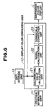
image converter according to the present embodiment. Fig. 6 is a block diagram showing the structure of a
display color conversion unit according to the present
embodiment. Fig. 7 is a block diagram showing the structure of a
signal calculation unit according to the present embodiment.
Best Mode for Carrying Out the Invention
Prior to the brief description of an embodiment of the
present invention, a principle used in the present invention
will now be described.
In representation using multiprimary colors (N primary
colors: N ≥ 4) more than three primary colors, even when
representation is performed so as to allow a specific
observer (for example, the standard observer) to recognize
the same color as an original color, in other words, even
when the human three-dimensional color perception conditions
are used as constraint conditions, (N-3) degree of freedom
remains.
According to the present principle, the remaining
degree of freedom is used under the constraint conditions
that colorimetric values match, and further, spectral
approximation is performed, so that fine color reproduction
for non-specific observers is realized. The principle will
now be described.
A spectrum at a certain pixel position in an image of a
subject to be reproduced is set to S(λ). A color
corresponding to the spectrum S(λ) is reproduced using an N-primary-color
display having N primary colors. The N-primary-color
display reproduces a color using additive
color mixture of the N primary colors.
In other words, a display spectrum S
d(λ) of the N-primary-color
display is expressed using an emission
spectrum S
i(λ) (i = 1 to N) of each primary color.
Where, αi denotes a display signal value of a primary
color i and is in the range given by the following
expression 2.
[Expression 2]
0≤α i ≤1 (i=1 ∼ N)
The constraint conditions for equalizing the XYZ
tristimulus values of S(λ) to those of Sd(λ) are expressed as
the following expression 3.
[Expression 3]
X=Xd ,Y=Yd,Z=Zd
Where, the respective left sides are expressed as
follows.
[Expression 4]
X=∫x(λ)S(λ)dλ,Y=∫y(λ)S(λ)dλ,Z=∫z(λ)S(λ)dλ
Using the above expression 1, the respective right
sides are expressed as follows.
Xi, Yi, and Zi are expressed respectively as follows.
[Expression 6]
Xi =∫x(λ)Si (λ)dλ,Yi =∫y(λ)Si (λ)dλ,Zi =∫z(λ)Si (λ)dλ
Simplifying the constraint conditions given by the
expression 3 using the foregoing expressions 4 and 5 gives a
determinant expressed as the following expression 7
representing conditions with respect to α
1 to α
N.
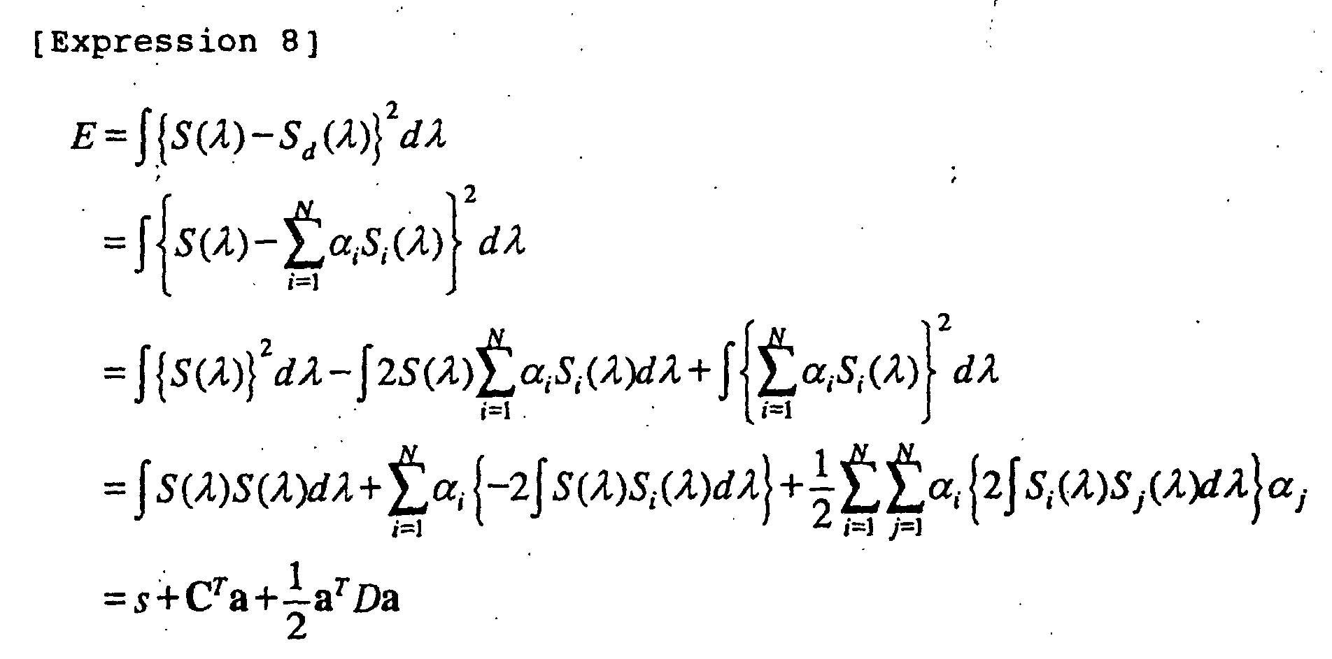
On the other hand, the amount of approximation
indicating how much is the display spectrum S
d(λ) of the N-primary-color
display approximate to the spectrum S(λ) of
the subject image is represented using squared errors E
expressed as the following expression 8.
Where, it is assumed as follows.
[Expression 9]
〈ss〉 = ∫S(λ)S(λ)dλ
〈ssi 〉=∫S(λ)Si (λ)dλ
〈sisj 〉=∫Si (λ)Sj (λ)dλ
On the assumption, reference symbols s, C, D, and a in the
expression 8 are expressed as the following expressions 10,
11, 12, and 13, respectively.
[Expression 10]
s=〈ss〉
As is understood from the expression 9, <sisj> = <sjsi>.
Thus, in the expression 12, D represents a symmetric matrix.
A superscript "T" denotes transposition of a matrix or
vectors.
In the above description, XYZ tristimulus values are
used as colorimetric values. When colorimetric values are
replaced with N colorimetric values calculated by using
arbitrary N functions, the similar description holds.
Further, in the above description, the squared errors E
are calculated using the difference, as it is, between the
display spectrum Sd(λ) of the N-primary-color display and the
spectrum S(λ) of the subject image. The calculation is not
limited to the above case. The respective spectra are
weighted using an arbitrary function W(λ) and, after that,
the squared error therebetween can be obtained. In this
case, S(λ) and Sd(λ) in the expression 8 can be replaced
respectively with S'(λ) and S'd(λ) given by the following
expression 14.
[Expression 14]
S'(λ)=W(λ)S(λ)
S'd (λ)=W(λ)Sd (λ)
It is a goal of the principle to obtain α1 to αN to
minimize the squared error E expressed as the expression 8
under the constraint conditions given by the expression 3,
namely, from among α1 to αN which satisfy the expression 7.
As is obvious from the expression 8, the squared error
E is given by a quadratic equation with respect to a. As is
clear from the expression 7, the constraint conditions are
given by a linear equation with respect to a. In other
words, this is a quadratic programming problem in which an
objective function is expressed as a quadratic equation and
constraint conditions are expressed as a linear equation.
Two means for solving the problem, namely, means using
Lagrange's method of undetermined coefficients and means
using the reduced gradient method will now be described
hereinbelow.
According to the former means using the Lagrange's
method of undetermined coefficients, a solution is obtained
without considering a possible range of a display signal
value of the primary color i, namely, the condition given by
the expression 2. When the obtained solution lies within
the range of the condition given by the expression 2, it is
the final solution.
According to the latter means using the reduced
gradient method, so long as the solution obtained using
Lagrange's method of undetermined coefficients is not within
the above range, the optimum solution is successively
obtained.
1. Solution Using Lagrange's Method of Undetermined
Coefficients
According to Lagrange's method of undetermined
coefficients, F is defined as expressed as the following
expression 15. α1 to αN, λX, λY, and λZ, which satisfy that
the gradient of F represents zero, are obtained, then α1 to
αN to minimize the squared error E given by the expression 8
are calculated under the constraint conditions given by the
expression 3.
[Expression 15]
F=E+λ XgX +λ YgY +λ ZgZ
Where, gX, gY, and gZ are defined by the following expression
16.
[Expression 16]
gX =X 1α1+X 2α2+···+XN α N -X
gY =Y 1α1+Y 2α2+···+YN α N -Y
gZ =Z 1 α 1+Z 2α2+···+ZN α N -Z
N conditional expressions, which are obtained by
partially differentiating F, expressed as the above
expression 15, with respect to α
1 to α
N respectively to be
equal to zero, is given by the following expression 17.
Three conditional expressions, which are obtained by
partially differentiating F, expressed as the foregoing
expression 15, such that λX, λY, and λZ are to be equal to
zero respectively, are the same as the foregoing expression
7.
Using the (N + 3) conditional expressions obtained as
mentioned above, α
1 to α
N, λ
X, λ
Y, and λ
Z are obtained. α
1 to
α
N, λ
X, λ
Y, and λ
Z are expressed as the following expression
18.
Whether each of α1 to αN, given by the expression 18,
satisfies the condition with respect to the dynamic range of
the display signal value of the primary color i expressed as
the expression 2 is determined. If each αi satisfies the
condition, the obtained α1 to αN represent the optimum
solution. When the number of αi which does not satisfy the
condition is one or more, the reduced gradient method, which
will be described hereinbelow, is used.
2. Solution Using Reduced Gradient Method
Summary of Reduced Gradient Method
The reduced gradient method is one of successive
approximations. According to the successive approximations,
in a convex function E(a) in which an element a (namely, a ∈
RN) of an N-dimensional Euclidean space RN is variable, in
order to obtain the minimum value, approximation is made
from a certain point a1 in a gradient downwardly in this
order of a2, a3, ... to be converged to the minimum point a*.
To utilize the reduced gradient method, the following
two conditions are needed.
For the condition (1), all of elements in Hessian
matrix D given by the expression 12 are positive. This
guarantees that a point in which the gradient indicates zero
is only the local minimum point and this point indicates the
optimum solution.
For the condition (2), it is easily understood that all
of points in a line segment, connecting two arbitrary points
in the feasible region, are included in the feasible region.
Thus, it is proved that the feasible region represents a
convex set.
Therefore, the reduced gradient method can be applied
to the problem of obtaining the minimum value of E(a)
expressed as the expression 8 under the limitations of the
expressions 2 and 3.
Transition between points in the reduced gradient
method is performed as follows.
A certain point a1 in the feasible region is set to a
starting point. First, a point aimed at advances from the
point a1 in the direction toward -▿E(a1). This direction is
opposite to the direction of the normal line to the level
surface of E(a1) passing through the point a1. In a manner,
the direction indicates the direction of the steepest
falling gradient.
The point advances from a1 in this direction and then
stops at a position where the gradient gradually changes
from the falling gradient to a rising gradient or at the end
of the boundary of the feasible region. The stop position
is set to a point a2.
The travelling direction is changed at this point a2.
The travelling direction must be determined such that the
angle which the travelling direction forms with -▿E(a1) is
90° or smaller and, when the point aimed at advances in the
direction, the point aimed at travels in the feasible region.
After that, in a manner similar to the above, the point
aimed at stops at a position where the gradient changes from
the falling gradient to the rising gradient or at the
boundary of the feasible region, the travelling direction is
changed, and the point aimed at successively advances in
this order of a3, a4, ... Even if the travelling direction
is changed within an angle of 90° or smaller, so long as
there is no more point in the feasible region in the changed
travelling direction, the last point is the optimum point.
A process according to the reduced gradient method will
now be specifically described. As a preparation to use the
method, gradient is first calculated.
In the expression 7, the matrix on the right side is
replaced by A and vectors on the left side are replaced by b.
Since vectors on the right side are already defined as a in
the expression 13, the expression 7 is expressed as b = Aa.
Since the expression 7 describes the three constraint
conditions with respect to α1 to αN, N variables include (N -
3) independent variables. The remaining three variables are
dependent variables.
On the basis of a base B of b = Aa, a is divided into a
basic variable (called as a dependent variable) a
B and a
nonbasic variable (independent variable) a
R. Similarly, the
matrix A is divided as A = [B | R]. In the following
description, to simplify the description, a
1, a
2, and a
3 are ;
set to basic variables and a
4, a
5, ..., and a
N are set to
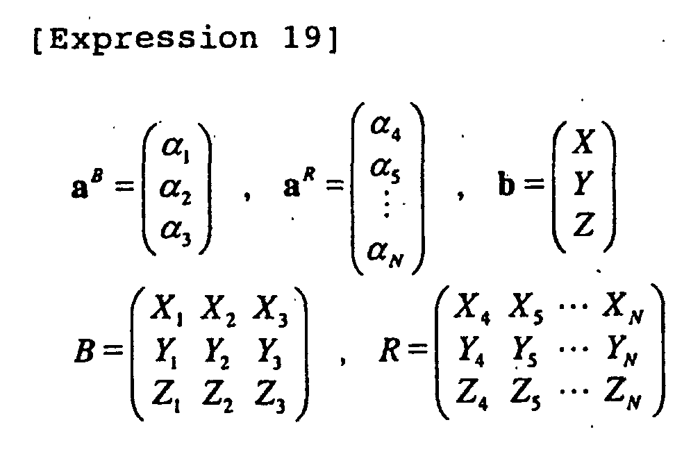
nonbasic variables. Those variables and matrices and the
vector b are expressed as the following expression 19.
On the basis of the above-mentioned basic variables and
nonbasic variables, redescribing of the foregoing expression
8 constituting the objective function gives the following
expression 20, rewriting of the expression 7 constituting
the constraint conditions gives the following expression 21,
and redescription of the expression 2 representing the
domain of variables gives the following expression 22.
[Expression 21]
Ba B +Ra R =b
[Expression 22]
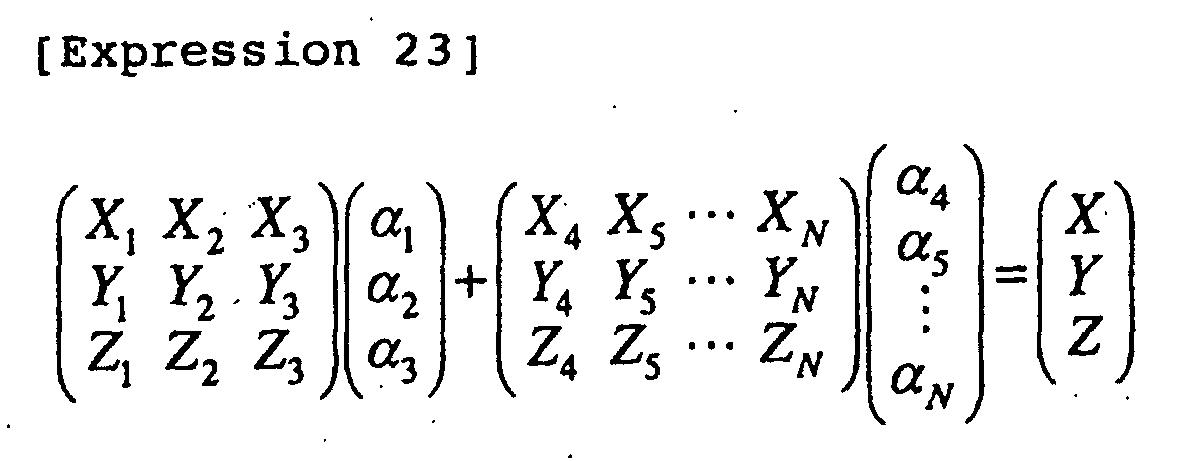
0≤a B ≤1,0≤a R ≤1 Explicit rewriting of the expression 21 gives the
following expression 23.
Multiplying both the sides of the expression 21, which
represents the constraint conditions, by B
-1 from the left
gives the following expression 24.
[Expression 24]
a B + B -1 Ra R = B -1b
Concrete rewriting of this expression so as to correspond to
the above expression 23 gives the following expression 25.
Expressing of the dependent variables α1 to α3 with
respect to the independent variables α4 to αN yields the
following expression 26.
[Expression 26]
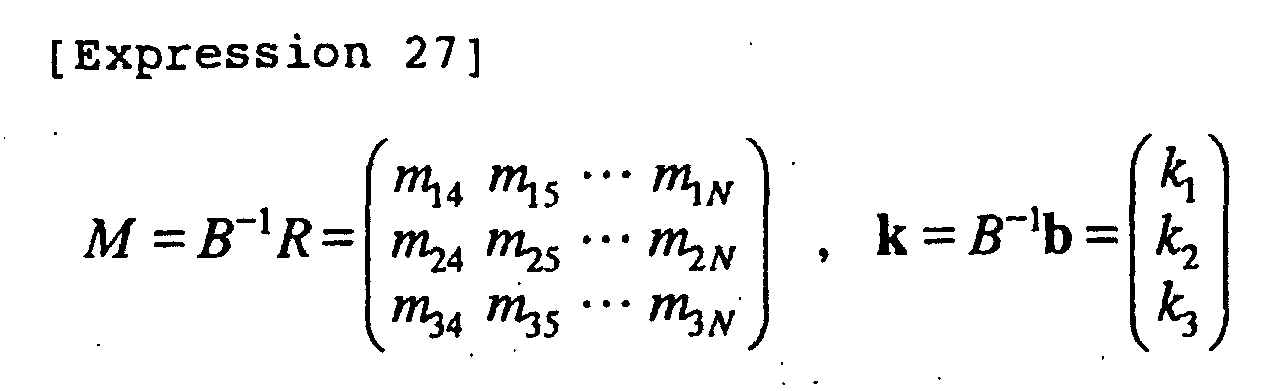
a B =-B -1 Ra R +B -1b=k-Ma R
Where, M and k are defined as expressed as the
following expression 27.
When M and k are defined as expressed as the expression
27, a unit table is expressed as the following table 1.
| b | α1 | α2 | α3 | α4 | α5 ··· αN |
| k1 | 1 | 0 | 0 | m14 | m15 ... m1N |
| k2 | 0 | 1 | 0 | m24 | m25 ... m2N |
| k3 | 0 | 0 | 1 | m34 | m35 ... m3N |
When the expression 26 is substituted into the
expression 20 representing the objective function to
eliminate aB, namely, α1 to α3, E(aB, aR) can be regarded as a
function with respect to only aR. Consequently, the
function is newly expressed as F(aR).
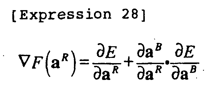
As mentioned above, after the independent variables are
clarified, the gradient of F(a
R) is calculated as expressed
as the following expression 28.
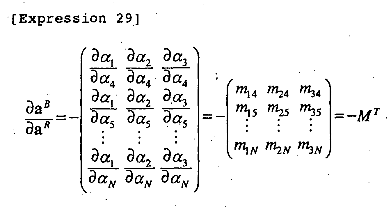
∂a
B/∂a
R in the second term on the right side of the
expression 28 are calculated as expressed as the following
expression 29 using the expressions 26 and 27.
Therefore, ▿F(a
R) given by the expression 28 is finally
expressed as the following expression 30.
After the preparation of the above-mentioned gradient
calculation, the reduced gradient method is performed
according to the following process.
<Step 1>
First, one point included in the feasible region,
namely, a solution which satisfies both of the expression 21
indicating the constraint conditions and the expression 22
indicating the domains of variables is found using any means.
The means for finding the solution include, for example,
means disclosed in "Color Conversion Method for Multiprimary
Display Using Matrix Switching", T. Ajito et al., OPTICAL
REVIEW, Vol. 8, No. 3, 2001, pp. 191-197 (document 5). The
obtained solution is set to
a expressed as the following
expression 31.
Subsequently, the direction in which a point aimed at
moves from
a R as a starting point is determined. A
direction vector in the travelling direction is given by the
following expression 32.
[Expression 32]
Δa R = (Δα4,Δα5,...,Δα N )
Where, the direction vector Δa
R points in the direction
which forms an angle of 90° or smaller with respect to the
direction opposite to the gradient in
a R and in which the
point aimed at is not out of the feasible region when the
point advances in the direction. Accordingly, when 4 ≤ i ≤
N, the direction vector can be set so as to satisfy the
following expression 33.
Where, on the right side of the expression 33; F is
partially differentiated with respect to α
i and, after that,
a is substituted for a value.
In other words, only when
α i is in the dynamic range or
when
α i is at the limit of the dynamic range but the
gradient points in the direction in which the gradient is in
the dynamic range,
α i is changed. In other cases,
α i is not
changed. With respect to Δa
R = (Δα
4, Δα
5, ..., Δα
N) obtained
as mentioned above, the following cases are possible.
<Step 3>
The point aimed at is advanced from the present point
expressed as the expression 31 to the limit of forward
movement in the travelling direction obtained by the above
step 2 within the feasible region. Alternatively, a point
at which the gradient changes from the falling gradient to
the rising gradient is found.
Therefore,
a R is replaced with the following expression
34.
1,
2, and
3 are calculated as expressed as the
following expression 35. Where,
1 represents an upper limit
which does not exceed the limit of the feasible region with
respect to the independent variables
α 4 to
α N ,
2 represents
an upper limit which does not exceed the limit of the
feasible region with respect to the dependent variables
α 1
to
α 3, and
3 represents a value which gives a point at which
the gradient changes from the falling gradient to the rising
gradient.
As expressed as the following expression 36, the
minimum value among 1, 2, and 3 is set to an increase limit
.
[Expression 36]
=min{1,2,3}
Depending on the value of the
obtained as mentioned
above, the process is changed as follows.
As mentioned above, the step 2 or 3 is repeated plural
times according to circumstances. When ΔaR = 0 as mentioned
above in the step 2, the target minimum point is obtained.
An embodiment of the present invention will now be
described hereinbelow with reference to the drawings.
Figs. 1 to 7 illustrate the embodiment of the present
invention. Fig. 1 is a diagram showing the schematic
structure of a color reproduction system.
The color reproduction system comprises: a multiband
camera 1 for shooting a subject 6 irradiated with a shooting
illumination light 5; an image converter 2 for converting a
color image supplied from the multiband camera 1 into a
color image to be output to a six-primary-color display 3,
which will be described later; and the six-primary-color
display 3 functioning as color image display means for
projecting the color image converted through the image
converter 2 on, for example, a screen 4.
The multiband camera 1 captures multiband image data,
for example, 16-band image data of the subject 6 irradiated
with the shooting illumination light 5 and then outputs the
captured image data to the image converter 2.
The image converter 2 converts the 16-band image data
supplied from the multiband camera 1 into six-primary-color
image data to be displayed by the six-primary-color display
3 and then outputs the resultant image data to the six-primary-color
display 3. The conversion will be described
in detail later.
The six-primary-color display 3 projects the six-primary-color
image data supplied from the image converter 2
onto, for example, the screen 4 to observably display the
image.
Fig. 2 is a diagram showing the structure of the
multiband camera 1.
Incident light from the subject 6 is converged by a
lens 1a and only light segments having predetermined
wavebands are allowed to pass through interference filters
1c, thus the image is formed on a monochrome CCD 1e.
The number of interference filters 1c is 16 so as to
correspond to 16 bands. The 16 interference filters 1c are
arranged in a filter turret 1b. The filter turret 1b is
rotated by a motor 1d, so that the interference filters 1c
are sequentially disposed in a light path between the lens
la and the monochrome CCD 1e. Synchronously with the
positioning of each interference filter 1c in the light path,
shooting is performed with the monochrome CCD 1e, thus
sequentially capturing subject images of 16 bands
constituting a spectral sensitivity and corresponding to the
respective interference filters 1c.
Fig. 3 is a diagram showing an example of the spectral
sensitivity of the multiband camera 1 having 16 bands.
Referring to Fig. 3, the multiband camera 1 has a
spectral sensitivity having 16 peaks generated at
substantially regular intervals in wavelengths of 380 to 780
nm. Multiband image data comprising 16 bands captured by
the multiband camera 1 is output to the image converter 2
and is then processed.
When the interference filters 1c of the filter turret
1b are changed, the 16-band spectral sensitivity can be
changed according to the application.
Fig. 4 is a diagram of an emission spectrum comprising
six primary colors of the six-primary-color display 3.
Six-primary-color emission spectral components p1(λ),
p2(λ), p3(λ), p4(λ), p5(λ), and p6(λ) are distributed at
substantially regular intervals in the wavelengths of 380 to
780 nm.
Fig. 5 is a block diagram showing the structure of the
image converter 2.
The image converter 2 comprises a spectrum estimation
unit 11, a display color conversion unit 12, and a data
storage unit 13.
The spectrum estimation unit 11 receives multiband
image data having 16 bands from the multiband camera 1,
calculates a subject spectrum constituting spectral data,
and then outputs the data to the display color conversion
unit 12 constituting color conversion means. For the
subject spectrum calculated by the spectrum estimation unit
11, as disclosed in, for example, the foregoing document 1,
spectral reflectance, obtained by spectral reflectance
calculation means, is multiplied by an illumination spectrum,
thus obtaining the subject spectrum.
The display color conversion unit 12 converts the
subject spectrum supplied from the spectrum estimation unit
11 into six-primary-color display signals using color
reproduction data of the six-primary-color display 3, the
color reproduction data being supplied from the data storage
unit 13, and then outputs the signals to the six-primary-color
display 3.
The color reproduction data of the six-primary-color
display 3 stored in the data storage unit 13 comprises an
emission spectrum of the respective primary colors and tone-scale
characteristics. The emission spectrum comprises 401
data arranged at intervals of 1 nm in the wavelengths of 380
to 780 nm. The tone-scale characteristics are data obtained
by applying display brightness, which is normalized such
that the maximum value equals to 1, to an input signal value
of each primary color for every predetermined sampling tone
scale.
Fig. 6 is a block diagram showing the structure of the
display color conversion unit 12.
The display color conversion unit 12 comprises a
colorimetric-value calculation unit 21, a signal calculation
unit 22, and a tone-scale correction unit 23.
The colorimetric-value calculation unit 21 calculates a
spectrum of the six-primary-color display 3 supplied from
the data storage unit 13 using the foregoing expression 6
and also calculates colorimetric values of the subject
spectrum supplied from the spectrum estimation unit 11 using
the foregoing expression 4.
A color matching function used for calculation of the
colorimetric values is selected from among color matching
function data, stored in the colorimetric-value calculation
unit 21, by the user of the image converter 2. As mentioned
above, the arbitrary number of functions can be used.
In this manner, the colorimetric-value calculation unit
21 outputs, to the signal calculation unit 22, the spectrum
including the primary colors of the six-primary-color
display 3 and the colorimetric values thereof, and the
subject spectrum and the colorimetric values thereof.
The signal calculation unit 22 receives the spectrum
including the primary colors of the six-primary-color
display 3 and the colorimetric values thereof, and the
subject spectrum and the colorimetric values thereof,
calculates display signal values of the six-primary-color
display 3, and then outputs the values to the tone-scale
correction unit 23.
In this instance, by setting, for example, the signal
calculation unit 22 can weight the subject spectrum and the
spectrum including the primary colors of the six-primary-color
display 3 on the basis of the expression 14.
The tone-scale correction unit 23 corrects the six-primary-color
display signals supplied from the signal
calculation unit 22 using the tone-scale characteristics
supplied from the data storage unit 13 and then outputs the
resultant signals to the six-primary-color display 3.
Fig. 7 is a block diagram showing the structure of the
signal calculation unit 22.
The signal calculation unit 22 comprises a user setting
unit 31, a linear-solution calculation unit 32, and a
nonlinear-solution calculation unit 33.
The user setting unit 31 outputs setting information,
indicating whether the linear-solution calculation unit 32
is used, to the linear-solution calculation unit 32 and also
generates another setting information, indicating whether
the nonlinear-solution calculation unit 33 is used, to the
nonlinear-solution calculation unit 33.
When the user setting unit 31 outputs the setting
information indicating the use of the linear-solution
calculation unit 32, the linear-solution calculation unit 32
calculates six-primary-color display signals for the subject
spectrum supplied from the spectrum estimation unit 11 and
then outputs the signals together with the subject spectrum
to the nonlinear-solution calculation unit 33.
On the other hand, if the user setting unit 31 outputs
the setting information indicating that the linear-solution
calculation unit 32 is not used, the linear-solution
calculation unit 32 outputs the subject spectrum supplied
from the spectrum estimation unit 11 as is to the nonlinear-solution
calculation unit 33.
When the user setting unit 31 outputs the other setting
information indicating the use of the nonlinear-solution
calculation unit 33, the nonlinear-solution calculation unit
33 receives the subject spectrum or six-primary-color
display signals from the linear-solution calculation unit 32.
When receiving the subject spectrum or the six-primary-color
display signals which are not within the range of 0 to
1, the nonlinear-solution calculation unit 33 calculates
six-primary-color display signals to be within the range of
0 to 1 and then outputs the obtained signals to the tone-scale
correction unit 23.
When receiving the six-primary-color display signals
which are within the range of 0 to 1, the nonlinear-solution
calculation unit 33 outputs the received six-primary-color
display signals to the tone-scale correction unit 23.
On the other hand, when the user setting unit 31
outputs the setting information indicating that the
nonlinear-solution calculation unit 33 is not used, the
nonlinear-solution calculation unit 33 outputs the received
six-primary-color display signals as they are to the tone-scale
correction unit 23. However, when the six-primary-color
display signals are not within the range of 0 to 1,
the nonlinear-solution calculation unit 33 maps the signal
values so as to be within the range of 0 to 1.
A process of calculating display signals in each of the
linear-solution calculation unit 32 and the nonlinear-solution
calculation unit 33 will now be described in more
detail.
The linear-solution calculation unit 32 calculates
display signals on the six-primary-color display 3 using
linear quadratic programming. Specifically, the unit 32
utilizes Lagrange's method of undetermined coefficients
described in the foregoing principle. In other words, the
linear-solution calculation unit 32 calculates display
signals α1 to α6 of the six-primary-color display 3 on the
basis of the expression 18 using the primary-color spectrum
for the six-primary-color display 3 and the colorimetric
values thereof supplied from the colorimetric-value
calculation unit 21, the colorimetric values of the subject
supplied from the colorimetric-value calculation unit 21,
and the subject spectrum supplied from the spectrum
estimation unit 11.
The nonlinear-solution calculation unit 33 calculates
display signals of the six-primary-color display 3 using
nonlinear quadratic programming. Specifically, the unit 33
utilizes the reduced gradient method described in the
foregoing principle. In other words, the nonlinear-solution
calculation unit 33 receives the subject spectrum, the
colorimetric values thereof, the spectrum of the six-primary-color
display 3, and the colorimetric values thereof
from the linear-solution calculation unit 32 and performs
the processing according to the above-mentioned steps of
<step 1> to <step 3> to calculate the display signals α1 to
α6 of the six-primary-color display 3.
The above-mentioned present embodiment intends to
display an image with an approximated spectrum. Accordingly,
even when statistical information regarding variations in
the color matching functions is unknown, faithful color
reproduction can be performed for many observers.
Since spectral approximation is performed under the
constraint conditions to match the colorimetric values,
faithful color reproduction for many observer can be
performed with higher accuracy.
Since the subject spectrum and the display spectrum are
properly weighted and the display spectrum is approximated
to the subject spectrum, faithful color reproduction for
many observers can be performed with higher accuracy.
In addition, since arbitrary color matching functions
can be used as color matching functions for calculating the
colorimetric values', a color matching function appropriate
for the observer and high-dimensional colorimetric values
indicating variations in the color matching functions can be
used. Thus, faithful color reproduction for many observers
can be performed with higher accuracy.
As a calculation method for spectral approximation,
least-squares approximation is used. Consequently, fast
calculation can be performed and faithful color reproduction
for many observers can be realized for the same processing
time as that of the existing system.
Even when a solution obtained by least-squares
approximation is not within the region feasible for display,
successive calculation is performed to obtain the optimum
solution in the region feasible for display.
In addition, in the successive calculation, it is
unnecessary to repeat the operation until the optimum
solution is obtained. The operation is appropriately
terminated to obtain a relatively accurate approximate
solution, thus resulting in a reduction in calculation time.
As mentioned above, even when there is no statistical
data regarding individual differences in color matching
functions, faithful color reproduction can be performed for
many more observers.
The present invention is not limited to the foregoing
embodiment but many modifications and variations are
possible within the spirit and scope of the present
invention.
Industrial Applicability
As mentioned above, according to the color reproduction
system of the present invention, faithful color reproduction
can be performed for many observers with variations in color
matching functions.