EP1450148A1 - Deviation Angle Detector - Google Patents
Deviation Angle Detector Download PDFInfo
- Publication number
- EP1450148A1 EP1450148A1 EP04002361A EP04002361A EP1450148A1 EP 1450148 A1 EP1450148 A1 EP 1450148A1 EP 04002361 A EP04002361 A EP 04002361A EP 04002361 A EP04002361 A EP 04002361A EP 1450148 A1 EP1450148 A1 EP 1450148A1
- Authority
- EP
- European Patent Office
- Prior art keywords
- windings
- resolvers
- deviation angle
- output
- sine
- Prior art date
- Legal status (The legal status is an assumption and is not a legal conclusion. Google has not performed a legal analysis and makes no representation as to the accuracy of the status listed.)
- Granted
Links
- 238000004804 winding Methods 0.000 claims abstract description 72
- 230000005284 excitation Effects 0.000 claims abstract description 12
- 238000010586 diagram Methods 0.000 description 5
- 238000000034 method Methods 0.000 description 3
- 238000012986 modification Methods 0.000 description 3
- 230000004048 modification Effects 0.000 description 3
- 230000005540 biological transmission Effects 0.000 description 2
- 238000001514 detection method Methods 0.000 description 2
- 230000006872 improvement Effects 0.000 description 2
- 230000009466 transformation Effects 0.000 description 1
Images


Classifications
-
- G—PHYSICS
- G01—MEASURING; TESTING
- G01D—MEASURING NOT SPECIALLY ADAPTED FOR A SPECIFIC VARIABLE; ARRANGEMENTS FOR MEASURING TWO OR MORE VARIABLES NOT COVERED IN A SINGLE OTHER SUBCLASS; TARIFF METERING APPARATUS; MEASURING OR TESTING NOT OTHERWISE PROVIDED FOR
- G01D5/00—Mechanical means for transferring the output of a sensing member; Means for converting the output of a sensing member to another variable where the form or nature of the sensing member does not constrain the means for converting; Transducers not specially adapted for a specific variable
- G01D5/12—Mechanical means for transferring the output of a sensing member; Means for converting the output of a sensing member to another variable where the form or nature of the sensing member does not constrain the means for converting; Transducers not specially adapted for a specific variable using electric or magnetic means
- G01D5/14—Mechanical means for transferring the output of a sensing member; Means for converting the output of a sensing member to another variable where the form or nature of the sensing member does not constrain the means for converting; Transducers not specially adapted for a specific variable using electric or magnetic means influencing the magnitude of a current or voltage
- G01D5/20—Mechanical means for transferring the output of a sensing member; Means for converting the output of a sensing member to another variable where the form or nature of the sensing member does not constrain the means for converting; Transducers not specially adapted for a specific variable using electric or magnetic means influencing the magnitude of a current or voltage by varying inductance, e.g. by a movable armature
- G01D5/204—Mechanical means for transferring the output of a sensing member; Means for converting the output of a sensing member to another variable where the form or nature of the sensing member does not constrain the means for converting; Transducers not specially adapted for a specific variable using electric or magnetic means influencing the magnitude of a current or voltage by varying inductance, e.g. by a movable armature by influencing the mutual induction between two or more coils
- G01D5/2073—Mechanical means for transferring the output of a sensing member; Means for converting the output of a sensing member to another variable where the form or nature of the sensing member does not constrain the means for converting; Transducers not specially adapted for a specific variable using electric or magnetic means influencing the magnitude of a current or voltage by varying inductance, e.g. by a movable armature by influencing the mutual induction between two or more coils by movement of a single coil with respect to two or more coils
-
- H—ELECTRICITY
- H03—ELECTRONIC CIRCUITRY
- H03M—CODING; DECODING; CODE CONVERSION IN GENERAL
- H03M1/00—Analogue/digital conversion; Digital/analogue conversion
- H03M1/12—Analogue/digital converters
- H03M1/64—Analogue/digital converters with intermediate conversion to phase of sinusoidal or similar periodical signals
- H03M1/645—Analogue/digital converters with intermediate conversion to phase of sinusoidal or similar periodical signals for position encoding, e.g. using resolvers or synchros
Definitions
- the present invention relates to deviation angle detectors, and particularly one in which the difference in the rotation angles of two resolvers is detected as a deviation angle.
- Conventional deviation angle detectors include a rotor, a stator, and a single excitation winding and multiple output windings, which are coiled around the stator.
- the difference in the rotation angles of the resolvers is detected as a deviation angle by calculating the output signal that corresponds to the rotation angles of the resolvers digitally or in analog.
- a typical deviation angle detector is used as a means to find a transmission torque by detecting the distortion angle of a power transmission angle.
- An example of such a deviation angle detector is discussed in Japanese Unexamined Patent Application Publications H11-321689 and 2001-272204.
- FIGS. 4 and 5 show conventional examples of a deviation angle detector.
- the deviation angle detector 100 shown in FIG. 4 includes two resolvers (variable reluctance resolvers) VR1 and VR2.
- Resolver VR1 includes rotor 110, stator 111, and single excitation windings (not shown) and multiple output windings 112 and 113 that are coiled around stator 111.
- Resolver VR2 includes rotor 120, stator 121, and single excitation windings (not shown) and multiple output windings 121 and 123 that are coiled around stator 121.
- the output signals Es1 and Es2 (sine signals) and Ec1 and Ec2 (cosine signals) from the output windings 112, 113 and 122, 123 from each of the resolvers VR1 and VR2 are input to each of the R/D converters (resolver digital converters) 114 and 124 and digitized. Then, the digitized signals are input to the controller 140 and calculated. Thus, the deviation angle ⁇ is calculated as the difference of the rotation angles ⁇ 1 and ⁇ 2 of the rotors 110 and 120 of each of the resolvers VR1 and VR2.
- deviation angle detector 100 employs a method in which each of the output signals E s1 , E s2 and E c1 , E c2 are separately calculated (can be an analog calculation) by using two resolvers VR1 and VR2, and therefore it requires two R/D converters 114 and 124, and consequently, there have been problems in terms of cost, space, processing speed, etc.
- each of the output windings 212, 222 and 213, 223 that correspond to each of the resolvers VR1 and VR2 is connected in parallel.
- the output signals Es1 and Es2 (sine signals) and Ec1 and Ec2 (cosine signals) that correspond to the difference in rotation angles (deviation angle) ⁇ is extracted from the connected portion.
- the output signals are input to the R/D converter 230.
- the digitized signal from the R/D converter 230 is input to the controller 240.
- the deviation angle ⁇ is calculated. According to this method, only one R/D converter 230 is required, and thus, the above-mentioned problem is solved.
- the maximum deviation angle ⁇ that can be detected with high precision is ⁇ 22.5° (see Japanese Unexamined Patent Application Publication 2001-272204). Therefore, a problem with conventional deviation angle detectors is that the application range of the detector 200 is limited.
- a deviation angle detector that solves problems such as cost, space and processing speed, and at the same time, enlarges the detectable deviation angle range in order to enlarge the application range.
- the deviation angle detector may be formed having two resolvers each including a rotor, a stator, and a single excitation winding and multiple output windings, which are coiled around the corresponding stator.
- the difference in the rotation angles of the resolvers is detected as a deviation angle.
- the detection is performed by calculating the output signal that corresponds to the rotation angles of the resolvers.
- the output signals are characterized by the serially connected output windings that correspond to the resolvers.
- the output signals are extracted from the serially connected output windings and digital or analog processing thereof can be carried out.
- the output windings of each of the resolvers include two types of windings that are coiled by shifting the phase by 90°.
- the output signals from the serially connected output windings may be input to a single analog or digital calculation converter.
- an output signal that corresponds to the difference in rotation angles, deviation angle ⁇ , of the resolvers is extracted from the serially connected output windings of the resolvers.
- the output signal requires only one analog or digital calculation converter, and consequently, a decrease in cost, economy of space and an improvement in processing speed can be achieved.
- each resolver when the output windings of each resolver includes two types of output windings that are coiled, shifting the phase by 90°, Es (sine signal) and Ec (cosine signal), which are output from serially connected output windings, can be represented by sine ( ⁇ ) and cosine ( ⁇ ), which are functions of the deviation angle ⁇ of the resolvers.
- FIG. 1 shows a circuit diagram of the deviation angle detector of the present invention.
- FIG. 2 shows a graphical illustration of the correlation between a deviation angle ⁇ and an output ratio (Es/Ec) detected by the deviation angle detector of FIG. 1.
- FIG. 3 shows a circuit diagram of the deviation angle detector of another embodiment of the present invention.
- FIG. 4 is a conventional circuit diagram of a deviation angle detector having two resolver digital converters.
- FIG. 5 is a conventional circuit diagram of a deviation angle detector having one resolver digital converter.
- FIG. 1 shows a circuit diagram of a deviation angle detector 1 of the present invention.
- the deviation angle detector 1 is has two resolvers (variable reluctance resolvers) VR1 and VR2, R/D converter 30, and a controller 40.
- the resolver VR1 includes a rotor 10, stator 11, and a single excitation winding (not shown) and multiple output windings 12 and 13 that are coiled around the stator 11.
- the output winding includes two types of coiled windings 12 and 13, thereby shifting the phase by 90°.
- Each of the windings output the sine element and the cosine element of the rotation angle ⁇ 1 of the rotor 10.
- the resolver VR2 includes a rotor 20, stator 21, and a single excitation winding (not shown) and multiple output windings 22 and 23 that are coiled around the stator 21.
- the output winding includes two types of coiled windings 22 and 23, thereby shifting the phase by 90°.
- Each of the windings output the sine element and the cosine element of the rotation angle ⁇ 1 of the rotor 20.
- the deviation angle detector 1 of the present embodiment is such that the output windings 12 and 22 corresponding to resolvers VR1 and VR2, respectively, output the sine element of the output signals.
- the output windings 12 and 22 are serially connected and output windings 13 and 23 that output the cosine element of the output signals are serially connected.
- the output signals Ec and Es are extracted from the serially connected output windings 12 and 22 and the output windings 13 and 23, and then they are input to the R/D converter 30 and digitized.
- the detection method of the deviation angle ⁇ is described in detail as follows.
- E VR1s KEsin ⁇ t ⁇ sin ⁇ 1
- E VR1c KEsin ⁇ t ⁇ xcos ⁇ 1
- ⁇ is the deviation angle of resolvers VR1 and VR2.
- sine output signal Es is:
- the sine output signal Es can be represented as a sine function of the deviation angle ⁇ of the resolvers VR1 and VR2.
- the cosine output element is:
- the cosine output signal Ec can be represented as the cosine function of the deviation angle ⁇ of the resolvers VR1 and VR2.
- Sine output element Es and cosine output element Ec that are represented in the aforementioned formulas (1) and (2) are input to single R/D converter 30 as described above, and digitized, and then input to the controller 40.
- the deviation angle ⁇ can be calculated.
- FIG. 2 shows a graphical illustration of formula (3) wherein the x-axis is the deviation angle ⁇ and the y-axis is the output ratio (Es/Ec).
- the range of the deviation angle ⁇ that can be detected by the deviation angle detector of the present invention is ⁇ 90° and it is significantly enlarged compared to the conventional range, which was ⁇ 22.5°.
- output signals Es and Ec which correspond to the difference in rotation angle (deviation angle) ⁇ of the resolvers VR1 and VR2 are extracted from serially connected output windings 12, 22 and 13 and 23 of the resolvers VR1 and VR2. Therefore, the deviation angle detector 1 requires only one R/D converter, and consequently, a decrease in cost, economy of space, a processing speed improvement, etc., can be achieved.
- the detectable range of the deviation angle ⁇ is enlarged up to ⁇ 90°, and therefore, the application range of the deviation angle detector 1 is enlarged.
- the output signals were extracted from the output windings and digitized; however, analog processing can be carried out, and in that case, a single analog calculation converter 30a can be used, as shown in FIG. 3.
- the present invention is a deviation angle detector having two resolvers that include a rotor, a stator, and single excitation windings and multiple output windings that are coiled around the stator.
- the difference in rotation angles of the resolvers is detected as a deviation angle by calculating the output signal that corresponds to the rotation angles of the resolvers digitally or in analog.
- the deviation angle detector described herein can solve the problems of, for example, cost, space and processing speed. Additionally, the detectable deviation angle range is enlarged and consequently, an effect can be achieved such that the application range of the deviation angle detector can be enlarged.
Landscapes
- Physics & Mathematics (AREA)
- General Physics & Mathematics (AREA)
- Transmission And Conversion Of Sensor Element Output (AREA)
- Measuring Fluid Pressure (AREA)
- Length Measuring Devices With Unspecified Measuring Means (AREA)
- Measurement Of Length, Angles, Or The Like Using Electric Or Magnetic Means (AREA)
Abstract
Description
- The present invention relates to deviation angle detectors, and particularly one in which the difference in the rotation angles of two resolvers is detected as a deviation angle.
- Conventional deviation angle detectors include a rotor, a stator, and a single excitation winding and multiple output windings, which are coiled around the stator. The difference in the rotation angles of the resolvers is detected as a deviation angle by calculating the output signal that corresponds to the rotation angles of the resolvers digitally or in analog. For example, a typical deviation angle detector is used as a means to find a transmission torque by detecting the distortion angle of a power transmission angle. An example of such a deviation angle detector is discussed in Japanese Unexamined Patent Application Publications H11-321689 and 2001-272204.
- FIGS. 4 and 5 show conventional examples of a deviation angle detector.
- The
deviation angle detector 100 shown in FIG. 4 includes two resolvers (variable reluctance resolvers) VR1 and VR2. Resolver VR1 includesrotor 110, stator 111, and single excitation windings (not shown) andmultiple output windings rotor 120,stator 121, and single excitation windings (not shown) andmultiple output windings stator 121. The output signals Es1 and Es2 (sine signals) and Ec1 and Ec2 (cosine signals) from theoutput windings controller 140 and calculated. Thus, the deviation angle Δ is calculated as the difference of the rotation angles 1 and 2 of therotors - However,
deviation angle detector 100 employs a method in which each of the output signals Es1, Es2 and Ec1, Ec2 are separately calculated (can be an analog calculation) by using two resolvers VR1 and VR2, and therefore it requires two R/D converters 114 and 124, and consequently, there have been problems in terms of cost, space, processing speed, etc. - Therefore, as with
deviation angle detector 200 shown in FIG. 5, a method has been proposed in which each of theoutput windings D converter 230. Next, the digitized signal from the R/D converter 230 is input to thecontroller 240. Thus, the deviation angle Δ is calculated. According to this method, only one R/D converter 230 is required, and thus, the above-mentioned problem is solved. - However, with the
deviation angle detector 200 shown in FIG. 5, the maximum deviation angle Δ that can be detected with high precision is ±22.5° (see Japanese Unexamined Patent Application Publication 2001-272204). Therefore, a problem with conventional deviation angle detectors is that the application range of thedetector 200 is limited. - In view of the above, a deviation angle detector is provided that solves problems such as cost, space and processing speed, and at the same time, enlarges the detectable deviation angle range in order to enlarge the application range.
- The deviation angle detector may be formed having two resolvers each including a rotor, a stator, and a single excitation winding and multiple output windings, which are coiled around the corresponding stator. The difference in the rotation angles of the resolvers is detected as a deviation angle. The detection is performed by calculating the output signal that corresponds to the rotation angles of the resolvers. The output signals are characterized by the serially connected output windings that correspond to the resolvers. The output signals are extracted from the serially connected output windings and digital or analog processing thereof can be carried out.
- Further, the output windings of each of the resolvers include two types of windings that are coiled by shifting the phase by 90°.
- Additionally, the output signals from the serially connected output windings may be input to a single analog or digital calculation converter.
- Therefore, in accordance with the present invention, an output signal that corresponds to the difference in rotation angles, deviation angle Δ, of the resolvers is extracted from the serially connected output windings of the resolvers. The output signal requires only one analog or digital calculation converter, and consequently, a decrease in cost, economy of space and an improvement in processing speed can be achieved.
- Further, when the output windings of each resolver includes two types of output windings that are coiled, shifting the phase by 90°, Es (sine signal) and Ec (cosine signal), which are output from serially connected output windings, can be represented by sine (Δ) and cosine (Δ), which are functions of the deviation angle Δ of the resolvers. The deviation angle Δ can be found with Δ = tan-1 (Es/Ec). Therefore, the detectable range of the deviation angle Δ is enlarged up to ±90° and the application range of the deviation angle detector is enlarged.
- The accompanying figures, in which like reference numerals refer to identical or functionally similar elements and which together with the detailed description below are incorporated in and form part of the specification, serve to further illustrate preferred embodiments and to explain various principles and advantages all in accordance with the present invention.
- FIG. 1 shows a circuit diagram of the deviation angle detector of the present invention.
- FIG. 2 shows a graphical illustration of the correlation between a deviation angle Δ and an output ratio (Es/Ec) detected by the deviation angle detector of FIG. 1.
- FIG. 3 shows a circuit diagram of the deviation angle detector of another embodiment of the present invention.
- FIG. 4 is a conventional circuit diagram of a deviation angle detector having two resolver digital converters.
- FIG. 5 is a conventional circuit diagram of a deviation angle detector having one resolver digital converter.
- FIG. 1 shows a circuit diagram of a
deviation angle detector 1 of the present invention. Thedeviation angle detector 1 is has two resolvers (variable reluctance resolvers) VR1 and VR2, R/D converter 30, and acontroller 40. - The resolver VR1 includes a
rotor 10, stator 11, and a single excitation winding (not shown) andmultiple output windings 12 and 13 that are coiled around the stator 11. Here, the output winding includes two types of coiledwindings 12 and 13, thereby shifting the phase by 90°. Each of the windings output the sine element and the cosine element of the rotation angle 1 of therotor 10. - Similarly, the resolver VR2 includes a
rotor 20,stator 21, and a single excitation winding (not shown) andmultiple output windings stator 21. Here, the output winding includes two types of coiledwindings rotor 20. - As described above, the
deviation angle detector 1 of the present embodiment is such that theoutput windings output windings output windings 13 and 23 that output the cosine element of the output signals are serially connected. Then, the output signals Ec and Es are extracted from the serially connectedoutput windings output windings 13 and 23, and then they are input to the R/D converter 30 and digitized. Based on the digitized output signals Es and Ec, the deviation angle Δ (Δ= 1-2) of the resolvers VR1 and VR2 is calculated by calculating it in thecontroller 40. - The detection method of the deviation angle Δ is described in detail as follows.
- When an alternating voltage: KEsinωt (K is a constant, E is a transformation ratio, ω is the angular frequency, and t is time) is applied as an input signal to the excitation windings (not shown) that are coiled around each of
stators 11 and 21 of each of the resolvers VR1 and VR2, the following signals are output to theoutput windings - Sine signal output EVR1s and cosine signal output EVR1c that are output from the
output windings 12 and 13 of the resolver VR1 are: - Sine signal output EVR2s and cosine signal output EVR2c that are output from the
output windings 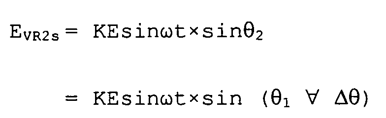
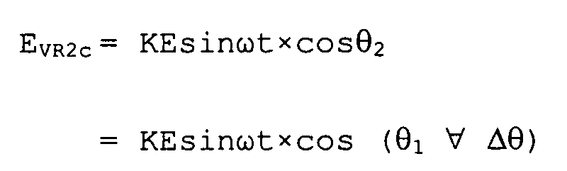
- Here, Δ is the deviation angle of resolvers VR1 and VR2.
- When the output windings that output the sine element of the output signal are serially connected and the output windings that output the cosine element of the output signals are serially connected, sine output signal Es is:


- Here, when the electric zero point of the resolvers VR1 and VR2 is set to zero, 1=0. Therefore, it is:

- Thus, the sine output signal Es can be represented as a sine function of the deviation angle Δ of the resolvers VR1 and VR2.
- Similarly, the cosine output element is:

- Here, when the electric zero point of the resolvers VR1 and VR2 is set to zero, 1=0. Therefore, it is:

- Thus, the cosine output signal Ec can be represented as the cosine function of the deviation angle Δ of the resolvers VR1 and VR2.
- The calculation of the deviation angle Δ is carried out as follows.
- Sine output element Es and cosine output element Ec that are represented in the aforementioned formulas (1) and (2) are input to single R/
D converter 30 as described above, and digitized, and then input to thecontroller 40. - Meanwhile, from the above-mentioned formulas (1) and (2), formulas (3) and (4) can be obtained as follows.
- Therefore, in accordance with formula (4), the deviation angle Δ can be calculated.
- FIG. 2 shows a graphical illustration of formula (3) wherein the x-axis is the deviation angle Δ and the y-axis is the output ratio (Es/Ec).
- As is clear from Figure 2, the range of the deviation angle Δ that can be detected by the deviation angle detector of the present invention is ±90° and it is significantly enlarged compared to the conventional range, which was ±22.5°.
- As described above, with the
deviation angle detector 1 of the present invention, output signals Es and Ec, which correspond to the difference in rotation angle (deviation angle) Δ of the resolvers VR1 and VR2, are extracted from serially connectedoutput windings deviation angle detector 1 requires only one R/D converter, and consequently, a decrease in cost, economy of space, a processing speed improvement, etc., can be achieved. - In addition, the detectable range of the deviation angle Δ is enlarged up to ±90°, and therefore, the application range of the
deviation angle detector 1 is enlarged. - In the illustrated embodiment, the output signals were extracted from the output windings and digitized; however, analog processing can be carried out, and in that case, a single
analog calculation converter 30a can be used, as shown in FIG. 3. - As is clear from the above description, the present invention is a deviation angle detector having two resolvers that include a rotor, a stator, and single excitation windings and multiple output windings that are coiled around the stator. The difference in rotation angles of the resolvers is detected as a deviation angle by calculating the output signal that corresponds to the rotation angles of the resolvers digitally or in analog.
- The corresponding output windings of the resolvers are connected in series and the output signal is extracted from the serially connected output windings and calculated digitally or in analog. Therefore, the deviation angle detector described herein can solve the problems of, for example, cost, space and processing speed. Additionally, the detectable deviation angle range is enlarged and consequently, an effect can be achieved such that the application range of the deviation angle detector can be enlarged.
- This disclosure is intended to explain how to fashion and use various embodiments in accordance with the invention rather than to limit the true, intended, and fair scope and spirit thereof. The foregoing description is not intended to be exhaustive or to limit the invention to the precise form disclosed. Modifications or variations are possible in light of the above teachings. The illustrated embodiment was chosen and described to provide the best illustration of the principles of the invention and its practical application, and to enable one of ordinary skill in the art to utilize the invention in various embodiments and with various modifications as are suited to the particular use contemplated. All such modifications and variations are within the scope of the invention as determined by the appended claims, as may be amended during the pendency of this application for patent, and all equivalents thereof, when interpreted in accordance with the breadth to which they are fairly, legally, and equitably entitled.
Claims (9)
- A deviation angle detector (1), comprising:a plurality of resolvers (VR1, VR2), wherein each of the resolvers (VR1, VR2) includes a rotor (10, 20), a stator (11, 21), a single excitation winding, and multiple output windings (12, 13, 22, 23), and each of the windings is coiled around a corresponding stator (11, 21), wherein:a difference in rotation angles between the resolvers (VR1, VR2) is detected as a deviation angle (Δ) by determining output signals (Ec, Es) that correspond to the rotation angles of each of the resolvers (VR1, VR2);the output windings (12, 13 and 22, 23) that correspond to each of the resolvers (VR1, VR2) are serially connected, and the output signals (Ec, Es) are extracted from the serially connected output windings (12, 13, 22, 23); andone of digital and analog processing is performed on the output signals (Ec, Es) of the resolvers (VR1, VR2).
- A deviation angle detector (1) in accordance with Claim 1, wherein the output windings (12, 13, 22, 23) of each of the resolvers (VR1, VR2) further comprise two types of windings (12, 13, 22, 23), the phases of which are shifted by 90°.
- A deviation angle detector (1) in accordance with Claim 1, wherein the output signals (Ec, Es) from the serially connected output windings (12, 13, 22, 23) are input to one of a single analog calculation converter (30a) and a single digital calculation converter (30).
- A deviation angle detector (1) in accordance with Claim 2, wherein the output signals (Ec, Es) from the serially connected output windings (12, 13, 22, 23) are input to one of a single analog calculation converter (30a) and a single digital calculation converter (30).
- A detector, comprising:a first resolver (VR1) including a first stator (11), first sine and cosine windings (12, 13) on the stator (11), the first sine and cosine windings (12, 13) being displaced from one another by ninety electrical degrees, a first excitation winding on the stator, and a first rotor (10) providing poles for varying the reluctance between windings (12, 13) according to a rotor position (1);a second resolver (VR2) including a second stator (21), second sine and cosine windings (22, 23) on the stator (21), the second sine and cosine windings (22, 23) being displaced from one another by ninety electrical degrees, a second excitation winding on the stator, and a second rotor (20) providing poles for varying the reluctance between windings according to a rotor position (2), wherein the first and second sine windings (12, 22) are serially connected and the first and second cosine windings (23, 23) are serially connected; anda controller (40) for calculating a deviation angle (Δ) of the first and second resolvers (VR1, VR2) based on an output signal (Es) from the serially connected sine windings (12, 22) and an output signal (Ec) from the serially connected cosine windings (23, 23).
- A detector in accordance with Claim 5, wherein the deviation angle (Δ) is represented by the equation Δ = (1 - 2).
- A detector in accordance with Claim 5, wherein the sine value of the first and second resolvers (VR1, VR2) is represented by Es, the cosine value of the first and second resolvers (VR1, VR2) is represented by Ec, and Δ = tan-1 (Es/Ec).
- A detector in accordance with Claim 5, wherein a range of the deviation angle Δ is ±90°.
- A detector in accordance with Claim 5, wherein the detector (1) includes a digital converter (30) connected to the first and second sine and cosine windings (12, 13, 22, 23) for converting sine and cosine values of the first and second resolvers (VR1, VR2) into digital values, wherein the controller (40) is connected to the digital converter (30) for receiving the digital values.
Applications Claiming Priority (2)
| Application Number | Priority Date | Filing Date | Title |
|---|---|---|---|
| JP2003027434A JP2004239689A (en) | 2003-02-04 | 2003-02-04 | Deviation angle detecting apparatus |
| JP2003027434 | 2003-02-04 |
Publications (2)
| Publication Number | Publication Date |
|---|---|
| EP1450148A1 true EP1450148A1 (en) | 2004-08-25 |
| EP1450148B1 EP1450148B1 (en) | 2008-08-13 |
Family
ID=32732890
Family Applications (1)
| Application Number | Title | Priority Date | Filing Date |
|---|---|---|---|
| EP04002361A Expired - Lifetime EP1450148B1 (en) | 2003-02-04 | 2004-02-03 | Deviation Angle Detector |
Country Status (5)
| Country | Link |
|---|---|
| US (1) | US7119536B2 (en) |
| EP (1) | EP1450148B1 (en) |
| JP (1) | JP2004239689A (en) |
| AT (1) | ATE404854T1 (en) |
| DE (1) | DE602004015655D1 (en) |
Cited By (1)
| Publication number | Priority date | Publication date | Assignee | Title |
|---|---|---|---|---|
| CN114706018A (en) * | 2022-04-18 | 2022-07-05 | 云南电网有限责任公司电力科学研究院 | Transformer winding deformation monitoring system and method |
Families Citing this family (3)
| Publication number | Priority date | Publication date | Assignee | Title |
|---|---|---|---|---|
| JP2005345454A (en) * | 2004-06-07 | 2005-12-15 | Minebea Co Ltd | Multiplex resolver continuous winding method and multiplex resolver |
| KR20240034843A (en) * | 2021-08-23 | 2024-03-14 | 파커-한니핀 코포레이션 | Systems and methods for controlling resolvers and motors with improved speed and direction monitoring |
| DE102022200058A1 (en) * | 2022-01-05 | 2023-07-06 | Robert Bosch Gesellschaft mit beschränkter Haftung | Angle sensor arrangement and method for angle determination |
Citations (5)
| Publication number | Priority date | Publication date | Assignee | Title |
|---|---|---|---|---|
| US3885209A (en) * | 1973-12-27 | 1975-05-20 | Astrosyst Inc | Two speed control systems |
| US4762007A (en) * | 1987-02-18 | 1988-08-09 | Allen-Brady Company, Inc. | Torque measuring apparatus |
| EP0527305A1 (en) * | 1991-06-17 | 1993-02-17 | Hughes Aircraft Company | Phase compensation for electromagnetic resolvers |
| EP0877464A2 (en) * | 1997-05-09 | 1998-11-11 | Kollmorgen Corporation | Variable reluctance resolver to digital converter |
| JP2001194251A (en) * | 2000-01-06 | 2001-07-19 | Tamagawa Seiki Co Ltd | Power steering detection device |
Family Cites Families (6)
| Publication number | Priority date | Publication date | Assignee | Title |
|---|---|---|---|---|
| US3641467A (en) * | 1969-05-13 | 1972-02-08 | Allis Chalmers Mfg Co | Rotary inductor |
| US3584276A (en) * | 1969-05-13 | 1971-06-08 | Allis Chalmers Mfg Co | Vehicle electric motor drive system |
| US3705343A (en) * | 1971-04-26 | 1972-12-05 | William L Ringland | Three phase rotary inductor vector adder |
| JP3414893B2 (en) * | 1995-07-12 | 2003-06-09 | オークマ株式会社 | Rotational position detector |
| JP3725694B2 (en) | 1998-05-20 | 2005-12-14 | 光洋精工株式会社 | Vehicle steering device |
| JP2001272204A (en) | 2000-03-24 | 2001-10-05 | Samutaku Kk | Torsion quantity measuring apparatus |
-
2003
- 2003-02-04 JP JP2003027434A patent/JP2004239689A/en not_active Withdrawn
-
2004
- 2004-01-29 US US10/766,322 patent/US7119536B2/en not_active Expired - Lifetime
- 2004-02-03 EP EP04002361A patent/EP1450148B1/en not_active Expired - Lifetime
- 2004-02-03 AT AT04002361T patent/ATE404854T1/en not_active IP Right Cessation
- 2004-02-03 DE DE602004015655T patent/DE602004015655D1/en not_active Expired - Lifetime
Patent Citations (5)
| Publication number | Priority date | Publication date | Assignee | Title |
|---|---|---|---|---|
| US3885209A (en) * | 1973-12-27 | 1975-05-20 | Astrosyst Inc | Two speed control systems |
| US4762007A (en) * | 1987-02-18 | 1988-08-09 | Allen-Brady Company, Inc. | Torque measuring apparatus |
| EP0527305A1 (en) * | 1991-06-17 | 1993-02-17 | Hughes Aircraft Company | Phase compensation for electromagnetic resolvers |
| EP0877464A2 (en) * | 1997-05-09 | 1998-11-11 | Kollmorgen Corporation | Variable reluctance resolver to digital converter |
| JP2001194251A (en) * | 2000-01-06 | 2001-07-19 | Tamagawa Seiki Co Ltd | Power steering detection device |
Cited By (1)
| Publication number | Priority date | Publication date | Assignee | Title |
|---|---|---|---|---|
| CN114706018A (en) * | 2022-04-18 | 2022-07-05 | 云南电网有限责任公司电力科学研究院 | Transformer winding deformation monitoring system and method |
Also Published As
| Publication number | Publication date |
|---|---|
| DE602004015655D1 (en) | 2008-09-25 |
| JP2004239689A (en) | 2004-08-26 |
| EP1450148B1 (en) | 2008-08-13 |
| ATE404854T1 (en) | 2008-08-15 |
| US20040257025A1 (en) | 2004-12-23 |
| US7119536B2 (en) | 2006-10-10 |
Similar Documents
| Publication | Publication Date | Title |
|---|---|---|
| JP7586585B2 (en) | Multi-phase resolver device and differential phase synthesis device | |
| US7088025B2 (en) | Variable-reluctance resolver and rotational angle sensor using same | |
| EP1498699A1 (en) | Rotational angle sensor and rotary electric machine comprising it | |
| WO2011104898A1 (en) | Method of detecting rotational angle or method of winding for synchronizing device windings | |
| JP2004151040A (en) | Rotation angle detection device and rotating electric machine | |
| US5250889A (en) | Variable reluctance resolver | |
| JP2001235307A (en) | Rotary type position detecting apparatus | |
| US20060022628A1 (en) | Motor control system | |
| EP1580534B1 (en) | High-accuracy 1X variable-reluctance resolver | |
| EP2650653A2 (en) | Resolver | |
| EP1450148B1 (en) | Deviation Angle Detector | |
| JP2021197895A (en) | Three-phase brushless motor and rotational position detection method for three-phase brushless motor | |
| JP2009523400A (en) | Method for determining the position of a rotor with at least one excitation winding of a synchronous electric machine | |
| JP4365654B2 (en) | Angular position detection device and driving device using the same | |
| JPH11118521A (en) | VR type resolver and resolver signal processing circuit | |
| EP1439629A1 (en) | Coaxial multiplex position detector and rotating machine using coaxial multiplex position detector | |
| WO2001071288A1 (en) | Torsional quantity measuring device | |
| EP1464924A2 (en) | R/D converter | |
| JP2012005327A (en) | Resolver | |
| CN113824234B (en) | Winding for reluctance type synchro and winding method thereof | |
| JP7186846B1 (en) | Control system for angle detector and AC rotating machine | |
| JP3704972B2 (en) | Rotor for variable reluctance resolver device | |
| US20070132448A1 (en) | Brushless resolver and its constructing method | |
| JPH0342516A (en) | Resolver signal transmission equipment | |
| JP4311523B2 (en) | Brushless resolver |
Legal Events
| Date | Code | Title | Description |
|---|---|---|---|
| PUAI | Public reference made under article 153(3) epc to a published international application that has entered the european phase |
Free format text: ORIGINAL CODE: 0009012 |
|
| AK | Designated contracting states |
Kind code of ref document: A1 Designated state(s): AT BE BG CH CY CZ DE DK EE ES FI FR GB GR HU IE IT LI LU MC NL PT RO SE SI SK TR |
|
| AX | Request for extension of the european patent |
Extension state: AL LT LV MK |
|
| 17P | Request for examination filed |
Effective date: 20050223 |
|
| AKX | Designation fees paid |
Designated state(s): AT BE BG CH CY CZ DE DK EE ES FI FR GB GR HU IE IT LI LU MC NL PT RO SE SI SK TR |
|
| 17Q | First examination report despatched |
Effective date: 20050412 |
|
| GRAP | Despatch of communication of intention to grant a patent |
Free format text: ORIGINAL CODE: EPIDOSNIGR1 |
|
| GRAS | Grant fee paid |
Free format text: ORIGINAL CODE: EPIDOSNIGR3 |
|
| GRAA | (expected) grant |
Free format text: ORIGINAL CODE: 0009210 |
|
| AK | Designated contracting states |
Kind code of ref document: B1 Designated state(s): AT BE BG CH CY CZ DE DK EE ES FI FR GB GR HU IE IT LI LU MC NL PT RO SE SI SK TR |
|
| REG | Reference to a national code |
Ref country code: GB Ref legal event code: FG4D |
|
| REG | Reference to a national code |
Ref country code: CH Ref legal event code: EP |
|
| REG | Reference to a national code |
Ref country code: IE Ref legal event code: FG4D |
|
| REF | Corresponds to: |
Ref document number: 602004015655 Country of ref document: DE Date of ref document: 20080925 Kind code of ref document: P |
|
| PG25 | Lapsed in a contracting state [announced via postgrant information from national office to epo] |
Ref country code: ES Free format text: LAPSE BECAUSE OF FAILURE TO SUBMIT A TRANSLATION OF THE DESCRIPTION OR TO PAY THE FEE WITHIN THE PRESCRIBED TIME-LIMIT Effective date: 20081124 Ref country code: NL Free format text: LAPSE BECAUSE OF FAILURE TO SUBMIT A TRANSLATION OF THE DESCRIPTION OR TO PAY THE FEE WITHIN THE PRESCRIBED TIME-LIMIT Effective date: 20080813 |
|
| PG25 | Lapsed in a contracting state [announced via postgrant information from national office to epo] |
Ref country code: FI Free format text: LAPSE BECAUSE OF FAILURE TO SUBMIT A TRANSLATION OF THE DESCRIPTION OR TO PAY THE FEE WITHIN THE PRESCRIBED TIME-LIMIT Effective date: 20080813 Ref country code: SI Free format text: LAPSE BECAUSE OF FAILURE TO SUBMIT A TRANSLATION OF THE DESCRIPTION OR TO PAY THE FEE WITHIN THE PRESCRIBED TIME-LIMIT Effective date: 20080813 Ref country code: AT Free format text: LAPSE BECAUSE OF FAILURE TO SUBMIT A TRANSLATION OF THE DESCRIPTION OR TO PAY THE FEE WITHIN THE PRESCRIBED TIME-LIMIT Effective date: 20080813 |
|
| PG25 | Lapsed in a contracting state [announced via postgrant information from national office to epo] |
Ref country code: BE Free format text: LAPSE BECAUSE OF FAILURE TO SUBMIT A TRANSLATION OF THE DESCRIPTION OR TO PAY THE FEE WITHIN THE PRESCRIBED TIME-LIMIT Effective date: 20080813 |
|
| PG25 | Lapsed in a contracting state [announced via postgrant information from national office to epo] |
Ref country code: DK Free format text: LAPSE BECAUSE OF FAILURE TO SUBMIT A TRANSLATION OF THE DESCRIPTION OR TO PAY THE FEE WITHIN THE PRESCRIBED TIME-LIMIT Effective date: 20080813 Ref country code: BG Free format text: LAPSE BECAUSE OF FAILURE TO SUBMIT A TRANSLATION OF THE DESCRIPTION OR TO PAY THE FEE WITHIN THE PRESCRIBED TIME-LIMIT Effective date: 20081113 |
|
| PG25 | Lapsed in a contracting state [announced via postgrant information from national office to epo] |
Ref country code: SK Free format text: LAPSE BECAUSE OF FAILURE TO SUBMIT A TRANSLATION OF THE DESCRIPTION OR TO PAY THE FEE WITHIN THE PRESCRIBED TIME-LIMIT Effective date: 20080813 Ref country code: RO Free format text: LAPSE BECAUSE OF FAILURE TO SUBMIT A TRANSLATION OF THE DESCRIPTION OR TO PAY THE FEE WITHIN THE PRESCRIBED TIME-LIMIT Effective date: 20080813 Ref country code: PT Free format text: LAPSE BECAUSE OF FAILURE TO SUBMIT A TRANSLATION OF THE DESCRIPTION OR TO PAY THE FEE WITHIN THE PRESCRIBED TIME-LIMIT Effective date: 20090113 Ref country code: CZ Free format text: LAPSE BECAUSE OF FAILURE TO SUBMIT A TRANSLATION OF THE DESCRIPTION OR TO PAY THE FEE WITHIN THE PRESCRIBED TIME-LIMIT Effective date: 20080813 |
|
| PLBE | No opposition filed within time limit |
Free format text: ORIGINAL CODE: 0009261 |
|
| STAA | Information on the status of an ep patent application or granted ep patent |
Free format text: STATUS: NO OPPOSITION FILED WITHIN TIME LIMIT |
|
| 26N | No opposition filed |
Effective date: 20090514 |
|
| PG25 | Lapsed in a contracting state [announced via postgrant information from national office to epo] |
Ref country code: EE Free format text: LAPSE BECAUSE OF FAILURE TO SUBMIT A TRANSLATION OF THE DESCRIPTION OR TO PAY THE FEE WITHIN THE PRESCRIBED TIME-LIMIT Effective date: 20080813 |
|
| PG25 | Lapsed in a contracting state [announced via postgrant information from national office to epo] |
Ref country code: IT Free format text: LAPSE BECAUSE OF FAILURE TO SUBMIT A TRANSLATION OF THE DESCRIPTION OR TO PAY THE FEE WITHIN THE PRESCRIBED TIME-LIMIT Effective date: 20080813 |
|
| PG25 | Lapsed in a contracting state [announced via postgrant information from national office to epo] |
Ref country code: MC Free format text: LAPSE BECAUSE OF NON-PAYMENT OF DUE FEES Effective date: 20090228 |
|
| REG | Reference to a national code |
Ref country code: CH Ref legal event code: PL |
|
| GBPC | Gb: european patent ceased through non-payment of renewal fee |
Effective date: 20090203 |
|
| PG25 | Lapsed in a contracting state [announced via postgrant information from national office to epo] |
Ref country code: CH Free format text: LAPSE BECAUSE OF NON-PAYMENT OF DUE FEES Effective date: 20090228 Ref country code: LI Free format text: LAPSE BECAUSE OF NON-PAYMENT OF DUE FEES Effective date: 20090228 |
|
| REG | Reference to a national code |
Ref country code: IE Ref legal event code: MM4A |
|
| PG25 | Lapsed in a contracting state [announced via postgrant information from national office to epo] |
Ref country code: SE Free format text: LAPSE BECAUSE OF FAILURE TO SUBMIT A TRANSLATION OF THE DESCRIPTION OR TO PAY THE FEE WITHIN THE PRESCRIBED TIME-LIMIT Effective date: 20081113 Ref country code: IE Free format text: LAPSE BECAUSE OF NON-PAYMENT OF DUE FEES Effective date: 20090203 |
|
| PG25 | Lapsed in a contracting state [announced via postgrant information from national office to epo] |
Ref country code: GB Free format text: LAPSE BECAUSE OF NON-PAYMENT OF DUE FEES Effective date: 20090203 |
|
| PG25 | Lapsed in a contracting state [announced via postgrant information from national office to epo] |
Ref country code: GR Free format text: LAPSE BECAUSE OF FAILURE TO SUBMIT A TRANSLATION OF THE DESCRIPTION OR TO PAY THE FEE WITHIN THE PRESCRIBED TIME-LIMIT Effective date: 20081114 |
|
| PG25 | Lapsed in a contracting state [announced via postgrant information from national office to epo] |
Ref country code: LU Free format text: LAPSE BECAUSE OF NON-PAYMENT OF DUE FEES Effective date: 20090203 |
|
| PG25 | Lapsed in a contracting state [announced via postgrant information from national office to epo] |
Ref country code: HU Free format text: LAPSE BECAUSE OF FAILURE TO SUBMIT A TRANSLATION OF THE DESCRIPTION OR TO PAY THE FEE WITHIN THE PRESCRIBED TIME-LIMIT Effective date: 20090214 |
|
| PG25 | Lapsed in a contracting state [announced via postgrant information from national office to epo] |
Ref country code: TR Free format text: LAPSE BECAUSE OF FAILURE TO SUBMIT A TRANSLATION OF THE DESCRIPTION OR TO PAY THE FEE WITHIN THE PRESCRIBED TIME-LIMIT Effective date: 20080813 |
|
| PG25 | Lapsed in a contracting state [announced via postgrant information from national office to epo] |
Ref country code: CY Free format text: LAPSE BECAUSE OF FAILURE TO SUBMIT A TRANSLATION OF THE DESCRIPTION OR TO PAY THE FEE WITHIN THE PRESCRIBED TIME-LIMIT Effective date: 20080813 |
|
| REG | Reference to a national code |
Ref country code: FR Ref legal event code: PLFP Year of fee payment: 13 |
|
| REG | Reference to a national code |
Ref country code: FR Ref legal event code: PLFP Year of fee payment: 14 |
|
| REG | Reference to a national code |
Ref country code: DE Ref legal event code: R082 Ref document number: 602004015655 Country of ref document: DE Representative=s name: KONLE, TILMAR, DIPL.-ING., DE Ref country code: DE Ref legal event code: R081 Ref document number: 602004015655 Country of ref document: DE Owner name: MINEBEA MITSUMI INC., JP Free format text: FORMER OWNER: MINEBEA CO., LTD., KITASAKU-GUN, NAGANO, JP |
|
| REG | Reference to a national code |
Ref country code: FR Ref legal event code: PLFP Year of fee payment: 15 |
|
| PGFP | Annual fee paid to national office [announced via postgrant information from national office to epo] |
Ref country code: DE Payment date: 20180123 Year of fee payment: 15 |
|
| PGFP | Annual fee paid to national office [announced via postgrant information from national office to epo] |
Ref country code: FR Payment date: 20180111 Year of fee payment: 15 |
|
| REG | Reference to a national code |
Ref country code: DE Ref legal event code: R119 Ref document number: 602004015655 Country of ref document: DE |
|
| PG25 | Lapsed in a contracting state [announced via postgrant information from national office to epo] |
Ref country code: DE Free format text: LAPSE BECAUSE OF NON-PAYMENT OF DUE FEES Effective date: 20190903 |
|
| PG25 | Lapsed in a contracting state [announced via postgrant information from national office to epo] |
Ref country code: FR Free format text: LAPSE BECAUSE OF NON-PAYMENT OF DUE FEES Effective date: 20190228 |