EP1450120A2 - Air circulation structure for a refrigerator machine room - Google Patents
Air circulation structure for a refrigerator machine room Download PDFInfo
- Publication number
- EP1450120A2 EP1450120A2 EP03256772A EP03256772A EP1450120A2 EP 1450120 A2 EP1450120 A2 EP 1450120A2 EP 03256772 A EP03256772 A EP 03256772A EP 03256772 A EP03256772 A EP 03256772A EP 1450120 A2 EP1450120 A2 EP 1450120A2
- Authority
- EP
- European Patent Office
- Prior art keywords
- vent
- machine room
- chamber
- main
- refrigerator
- Prior art date
- Legal status (The legal status is an assumption and is not a legal conclusion. Google has not performed a legal analysis and makes no representation as to the accuracy of the status listed.)
- Withdrawn
Links
Images


Classifications
-
- F—MECHANICAL ENGINEERING; LIGHTING; HEATING; WEAPONS; BLASTING
- F25—REFRIGERATION OR COOLING; COMBINED HEATING AND REFRIGERATION SYSTEMS; HEAT PUMP SYSTEMS; MANUFACTURE OR STORAGE OF ICE; LIQUEFACTION SOLIDIFICATION OF GASES
- F25D—REFRIGERATORS; COLD ROOMS; ICE-BOXES; COOLING OR FREEZING APPARATUS NOT OTHERWISE PROVIDED FOR
- F25D23/00—General constructional features
- F25D23/003—General constructional features for cooling refrigerating machinery
-
- F—MECHANICAL ENGINEERING; LIGHTING; HEATING; WEAPONS; BLASTING
- F25—REFRIGERATION OR COOLING; COMBINED HEATING AND REFRIGERATION SYSTEMS; HEAT PUMP SYSTEMS; MANUFACTURE OR STORAGE OF ICE; LIQUEFACTION SOLIDIFICATION OF GASES
- F25D—REFRIGERATORS; COLD ROOMS; ICE-BOXES; COOLING OR FREEZING APPARATUS NOT OTHERWISE PROVIDED FOR
- F25D23/00—General constructional features
-
- F—MECHANICAL ENGINEERING; LIGHTING; HEATING; WEAPONS; BLASTING
- F25—REFRIGERATION OR COOLING; COMBINED HEATING AND REFRIGERATION SYSTEMS; HEAT PUMP SYSTEMS; MANUFACTURE OR STORAGE OF ICE; LIQUEFACTION SOLIDIFICATION OF GASES
- F25B—REFRIGERATION MACHINES, PLANTS OR SYSTEMS; COMBINED HEATING AND REFRIGERATION SYSTEMS; HEAT PUMP SYSTEMS
- F25B2500/00—Problems to be solved
- F25B2500/12—Sound
-
- F—MECHANICAL ENGINEERING; LIGHTING; HEATING; WEAPONS; BLASTING
- F25—REFRIGERATION OR COOLING; COMBINED HEATING AND REFRIGERATION SYSTEMS; HEAT PUMP SYSTEMS; MANUFACTURE OR STORAGE OF ICE; LIQUEFACTION SOLIDIFICATION OF GASES
- F25D—REFRIGERATORS; COLD ROOMS; ICE-BOXES; COOLING OR FREEZING APPARATUS NOT OTHERWISE PROVIDED FOR
- F25D17/00—Arrangements for circulating cooling fluids; Arrangements for circulating gas, e.g. air, within refrigerated spaces
- F25D17/04—Arrangements for circulating cooling fluids; Arrangements for circulating gas, e.g. air, within refrigerated spaces for circulating air, e.g. by convection
- F25D17/06—Arrangements for circulating cooling fluids; Arrangements for circulating gas, e.g. air, within refrigerated spaces for circulating air, e.g. by convection by forced circulation
- F25D17/062—Arrangements for circulating cooling fluids; Arrangements for circulating gas, e.g. air, within refrigerated spaces for circulating air, e.g. by convection by forced circulation in household refrigerators
-
- F—MECHANICAL ENGINEERING; LIGHTING; HEATING; WEAPONS; BLASTING
- F25—REFRIGERATION OR COOLING; COMBINED HEATING AND REFRIGERATION SYSTEMS; HEAT PUMP SYSTEMS; MANUFACTURE OR STORAGE OF ICE; LIQUEFACTION SOLIDIFICATION OF GASES
- F25D—REFRIGERATORS; COLD ROOMS; ICE-BOXES; COOLING OR FREEZING APPARATUS NOT OTHERWISE PROVIDED FOR
- F25D2201/00—Insulation
- F25D2201/30—Insulation with respect to sound
-
- F—MECHANICAL ENGINEERING; LIGHTING; HEATING; WEAPONS; BLASTING
- F25—REFRIGERATION OR COOLING; COMBINED HEATING AND REFRIGERATION SYSTEMS; HEAT PUMP SYSTEMS; MANUFACTURE OR STORAGE OF ICE; LIQUEFACTION SOLIDIFICATION OF GASES
- F25D—REFRIGERATORS; COLD ROOMS; ICE-BOXES; COOLING OR FREEZING APPARATUS NOT OTHERWISE PROVIDED FOR
- F25D2317/00—Details or arrangements for circulating cooling fluids; Details or arrangements for circulating gas, e.g. air, within refrigerated spaces, not provided for in other groups of this subclass
- F25D2317/06—Details or arrangements for circulating cooling fluids; Details or arrangements for circulating gas, e.g. air, within refrigerated spaces, not provided for in other groups of this subclass with forced air circulation
- F25D2317/065—Details or arrangements for circulating cooling fluids; Details or arrangements for circulating gas, e.g. air, within refrigerated spaces, not provided for in other groups of this subclass with forced air circulation characterised by the air return
- F25D2317/0655—Details or arrangements for circulating cooling fluids; Details or arrangements for circulating gas, e.g. air, within refrigerated spaces, not provided for in other groups of this subclass with forced air circulation characterised by the air return through the top
-
- F—MECHANICAL ENGINEERING; LIGHTING; HEATING; WEAPONS; BLASTING
- F25—REFRIGERATION OR COOLING; COMBINED HEATING AND REFRIGERATION SYSTEMS; HEAT PUMP SYSTEMS; MANUFACTURE OR STORAGE OF ICE; LIQUEFACTION SOLIDIFICATION OF GASES
- F25D—REFRIGERATORS; COLD ROOMS; ICE-BOXES; COOLING OR FREEZING APPARATUS NOT OTHERWISE PROVIDED FOR
- F25D2317/00—Details or arrangements for circulating cooling fluids; Details or arrangements for circulating gas, e.g. air, within refrigerated spaces, not provided for in other groups of this subclass
- F25D2317/06—Details or arrangements for circulating cooling fluids; Details or arrangements for circulating gas, e.g. air, within refrigerated spaces, not provided for in other groups of this subclass with forced air circulation
- F25D2317/066—Details or arrangements for circulating cooling fluids; Details or arrangements for circulating gas, e.g. air, within refrigerated spaces, not provided for in other groups of this subclass with forced air circulation characterised by the air supply
- F25D2317/0665—Details or arrangements for circulating cooling fluids; Details or arrangements for circulating gas, e.g. air, within refrigerated spaces, not provided for in other groups of this subclass with forced air circulation characterised by the air supply from the top
-
- F—MECHANICAL ENGINEERING; LIGHTING; HEATING; WEAPONS; BLASTING
- F25—REFRIGERATION OR COOLING; COMBINED HEATING AND REFRIGERATION SYSTEMS; HEAT PUMP SYSTEMS; MANUFACTURE OR STORAGE OF ICE; LIQUEFACTION SOLIDIFICATION OF GASES
- F25D—REFRIGERATORS; COLD ROOMS; ICE-BOXES; COOLING OR FREEZING APPARATUS NOT OTHERWISE PROVIDED FOR
- F25D2317/00—Details or arrangements for circulating cooling fluids; Details or arrangements for circulating gas, e.g. air, within refrigerated spaces, not provided for in other groups of this subclass
- F25D2317/06—Details or arrangements for circulating cooling fluids; Details or arrangements for circulating gas, e.g. air, within refrigerated spaces, not provided for in other groups of this subclass with forced air circulation
- F25D2317/068—Details or arrangements for circulating cooling fluids; Details or arrangements for circulating gas, e.g. air, within refrigerated spaces, not provided for in other groups of this subclass with forced air circulation characterised by the fans
- F25D2317/0683—Details or arrangements for circulating cooling fluids; Details or arrangements for circulating gas, e.g. air, within refrigerated spaces, not provided for in other groups of this subclass with forced air circulation characterised by the fans the fans not of the axial type
-
- F—MECHANICAL ENGINEERING; LIGHTING; HEATING; WEAPONS; BLASTING
- F25—REFRIGERATION OR COOLING; COMBINED HEATING AND REFRIGERATION SYSTEMS; HEAT PUMP SYSTEMS; MANUFACTURE OR STORAGE OF ICE; LIQUEFACTION SOLIDIFICATION OF GASES
- F25D—REFRIGERATORS; COLD ROOMS; ICE-BOXES; COOLING OR FREEZING APPARATUS NOT OTHERWISE PROVIDED FOR
- F25D2323/00—General constructional features not provided for in other groups of this subclass
- F25D2323/002—Details for cooling refrigerating machinery
- F25D2323/0026—Details for cooling refrigerating machinery characterised by the incoming air flow
- F25D2323/00267—Details for cooling refrigerating machinery characterised by the incoming air flow through the side
-
- F—MECHANICAL ENGINEERING; LIGHTING; HEATING; WEAPONS; BLASTING
- F25—REFRIGERATION OR COOLING; COMBINED HEATING AND REFRIGERATION SYSTEMS; HEAT PUMP SYSTEMS; MANUFACTURE OR STORAGE OF ICE; LIQUEFACTION SOLIDIFICATION OF GASES
- F25D—REFRIGERATORS; COLD ROOMS; ICE-BOXES; COOLING OR FREEZING APPARATUS NOT OTHERWISE PROVIDED FOR
- F25D2323/00—General constructional features not provided for in other groups of this subclass
- F25D2323/002—Details for cooling refrigerating machinery
- F25D2323/0026—Details for cooling refrigerating machinery characterised by the incoming air flow
- F25D2323/00268—Details for cooling refrigerating machinery characterised by the incoming air flow through the top
-
- F—MECHANICAL ENGINEERING; LIGHTING; HEATING; WEAPONS; BLASTING
- F25—REFRIGERATION OR COOLING; COMBINED HEATING AND REFRIGERATION SYSTEMS; HEAT PUMP SYSTEMS; MANUFACTURE OR STORAGE OF ICE; LIQUEFACTION SOLIDIFICATION OF GASES
- F25D—REFRIGERATORS; COLD ROOMS; ICE-BOXES; COOLING OR FREEZING APPARATUS NOT OTHERWISE PROVIDED FOR
- F25D2323/00—General constructional features not provided for in other groups of this subclass
- F25D2323/002—Details for cooling refrigerating machinery
- F25D2323/0027—Details for cooling refrigerating machinery characterised by the out-flowing air
- F25D2323/00277—Details for cooling refrigerating machinery characterised by the out-flowing air from the side
-
- F—MECHANICAL ENGINEERING; LIGHTING; HEATING; WEAPONS; BLASTING
- F25—REFRIGERATION OR COOLING; COMBINED HEATING AND REFRIGERATION SYSTEMS; HEAT PUMP SYSTEMS; MANUFACTURE OR STORAGE OF ICE; LIQUEFACTION SOLIDIFICATION OF GASES
- F25D—REFRIGERATORS; COLD ROOMS; ICE-BOXES; COOLING OR FREEZING APPARATUS NOT OTHERWISE PROVIDED FOR
- F25D2323/00—General constructional features not provided for in other groups of this subclass
- F25D2323/002—Details for cooling refrigerating machinery
- F25D2323/0027—Details for cooling refrigerating machinery characterised by the out-flowing air
- F25D2323/00278—Details for cooling refrigerating machinery characterised by the out-flowing air from the top
-
- F—MECHANICAL ENGINEERING; LIGHTING; HEATING; WEAPONS; BLASTING
- F25—REFRIGERATION OR COOLING; COMBINED HEATING AND REFRIGERATION SYSTEMS; HEAT PUMP SYSTEMS; MANUFACTURE OR STORAGE OF ICE; LIQUEFACTION SOLIDIFICATION OF GASES
- F25D—REFRIGERATORS; COLD ROOMS; ICE-BOXES; COOLING OR FREEZING APPARATUS NOT OTHERWISE PROVIDED FOR
- F25D2400/00—General features of, or devices for refrigerators, cold rooms, ice-boxes, or for cooling or freezing apparatus not covered by any other subclass
- F25D2400/06—Refrigerators with a vertical mullion
-
- F—MECHANICAL ENGINEERING; LIGHTING; HEATING; WEAPONS; BLASTING
- F25—REFRIGERATION OR COOLING; COMBINED HEATING AND REFRIGERATION SYSTEMS; HEAT PUMP SYSTEMS; MANUFACTURE OR STORAGE OF ICE; LIQUEFACTION SOLIDIFICATION OF GASES
- F25D—REFRIGERATORS; COLD ROOMS; ICE-BOXES; COOLING OR FREEZING APPARATUS NOT OTHERWISE PROVIDED FOR
- F25D2400/00—General features of, or devices for refrigerators, cold rooms, ice-boxes, or for cooling or freezing apparatus not covered by any other subclass
- F25D2400/18—Aesthetic features
Definitions
- the present invention relates, in general, to refrigerators, and more particularly, though not exclusively, to a refrigerator in which the machine room has an improved air circulation structure.
- refrigerators produce cool air using evaporators, and then supply the cool air into storage compartments contained in the refrigerator cabinets, thus preserving the freshness of stored foods.
- the storage capacity of the refrigerators has increased greatly.
- Side-by-side style refrigerators in which the refrigerator compartment and the freezer compartment are placed side-by-side have become increasingly popular. These side-by-side style refrigerators have become increasingly popular due to their food storage efficiency, both in terms of space and access to food, as well as to their ability to preserve food.
- a refrigerator including a cabinet defining a storage compartment therein, a machine room located at a top of the cabinet, a main intake vent located at an upper surface of the machine room, a main exhaust vent located at an upper surface of the machine room, the main intake vent and the main outlet vent being located so as to allow air to circulate through the machine room.
- the machine room is horizontally and vertically formed along a front portion of the top of the cabinet, with the main intake vent and the main exhaust vent located side-by-side at the upper surface of the machine room.
- the interior of the machine room is partitioned into front and rear chambers by a noise buffering plate having a plurality of vent holes.
- a compressor, a condenser and a cooling fan are installed in the rear chamber of the machine room.
- a partition plate is provided in the front chamber of the machine room so as to divide the interior of the front chamber into an intake chamber, communicating with the main intake vent, and an exhaust chamber, communicating with the main exhaust vent.
- the vent holes are formed through the noise buffering plate such that a group of vent holes are formed at each side of the noise buffering plate to correspond to each of the main intake vent and the main exhaust vent.
- the condenser, the cooling fan and the compressor are sequentially arranged in the rear chamber of the machine room in a direction from a position around the inlet hole to another position around the outlet hole.
- a sub-intake vent and a sub-exhaust vent are respectively provided at both side edges of the upper surface of the machine room to accomplish an auxiliary circulation of air through the machine room.
- a refrigerator comprising: a cabinet defining a storage compartment therein; a machine room defined at a top of the cabinet, comprising: a compressor; a condenser; a cool air circulation fan; and a noise buffering plate, to partition the machine room into a front chamber and a rear chamber, the noise buffering plate having a plurality of vent holes to allow air flow between the front chamber and the rear chamber; a partition plate, dividing the front chamber into a front intake chamber and a front exhaust chamber; a main intake vent, located at an upper surface of the front intake chamber; a main exhaust vent, located at an upper surface of the front exhaust chamber; and a sub-intake vent and a sub-exhaust vent respectively provided at both side edges of the upper surface of the machine room to accomplish an auxiliary circulation of air through the machine room.
- a refrigerator comprising: a cabinet defining a storage compartment therein; and a machine room, comprising; a compressor; a condenser; a cool air circulation fan; and a noise buffering plate; the noise buffering plate positioned in the machine room so as to dampen operational noise from the compressor, condenser, and cool air circulation fan.
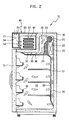
- FIGS. 1 and 2 are views showing a construction of a refrigerator, according to an embodiment of the present invention.
- a storage compartment defined in a cabinet 10 of the refrigerator is partitioned into left and right compartments by an intermediate partition wall 11.
- the left compartment forms a freezer compartment 12, while the right compartment forms a refrigerator compartment 13.
- a freezer compartment door 14 is mounted by hinges to an open front of the freezer compartment 12, and a refrigerator compartment door 15 is mounted by hinges to an open front of the refrigerator compartment 13, so that the freezer and refrigerator compartments 12 and 13 are closed or opened by the freezer and refrigerator compartment doors 14 and 15.
- a plurality of racks 16 are installed in each of the two compartments 12 and 13, and on an inner surface of each of the two doors 14 and 15 to store food in the two compartments 12 and 13.
- a top of the cabinet 10 is projected upward at a rear portion thereof to form an upper projection 18.
- the upper projection 18 defines two air-cooling chambers 20 therein, with an evaporator 24 and a cool air circulation fan 25 installed in each of the two air-cooling chambers 20. Due to the upper projection 18, the upper sections of the freezer and refrigerator compartments 12 and 13 are extended upward along rear portions thereof to produce the two air-cooling chambers 20 which are horizontally and vertically formed along the rear portions of the upper sections of the freezer and refrigerator compartments 12 and 13, respectively.
- the upper projection 18 is integrated with the cabinet 10, and is formed with a wall made of a thermal insulation material in the same manner as the cabinet 10 to thermally insulate the air-cooling chambers 20 from the atmosphere.
- the two air-cooling chambers 20 are connected at their lower portions with the freezer and refrigerator compartments 12 and 13, respectively.
- an air path partition plate 28 is provided in the air-cooling chamber 20 placed in the refrigerator compartment 11, as shown in FIG. 1, so as to partition the interior of the air-cooling chamber 20 into a front space 21 and a rear space 22.
- the air path partition plate 28 is spaced apart from an upper surface of the air-cooling chamber 20 by a predetermined gap, thus forming a flow path 23 through which the front and rear spaces 21 and 22 communicate with each other.
- the evaporator 24 is installed in the rear space 22 to produce cool air
- the cool air circulation fan 25 is installed in the flow path 23 above the evaporator 24.
- the cool air circulation fan 25 is a cross-flow fan which horizontally extends in the air-cooling chamber 20 so as to have a length almost equal to a length of the air-cooling chamber 20, and is positioned so as to be close to an upper edge of the air path partition plate 28.
- a drive motor 26 is connected to an end of the cross-flow fan 25.
- the cross-flow fan 25 thus forces air from the rear space 22 housing the evaporator 24 into the front space 21.
- the cross-flow fan 25 installed in the flow path 23 smoothly circulates the cool air through an entire area of the flow path 23, without resistance.
- An air suction path 31 is provided at the rear portion of the refrigerator compartment 13 to allow the air to flow from the refrigerator compartment 13 into the rear space 22 housing the evaporator 24, when the cool air circulation fan 25 is operated.
- An air exhaust path 32 is provided at the upper portion of the refrigerator compartment 13 so as to uniformly discharge the cool air from the air-cooling chamber 20 into the entire area of the upper portion of the refrigerator compartment 13.
- the air suction path 31 is formed by a panel-type air suction guide member 33 which is vertically installed along a rear surface of the refrigerator compartment 13.
- the air suction guide member 33 is connected at its upper end to the lower end of the air path partition plate 28, thus forming a vertical channel between the air suction guide member 33 and the rear surface of the refrigerator compartment 13.
- a plurality of air suction ports 34 are formed through the air suction guide member 33.
- the air exhaust path 32 is formed by a panel-type air exhaust guide member 35 which is mounted to the upper surface of the refrigerator compartment 13 and is connected at its rear end to the lower end of the air path partition plate 28 and is spaced apart from the upper surface of the refrigerator compartment 13.
- a plurality of air exhaust ports 36 are formed through the air exhaust guide member 35.
- the freezer compartment 12 has the same air path structure as that of the refrigerator compartment 13, so that the air path structure of the freezer compartment 12 is omitted from the description.
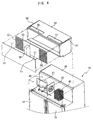
- a machine room 40 is horizontally and vertically formed on the top of the cabinet 10 at a position in front of the upper projection 18, and houses a variety of electric devices, such as a compressor 41, a condenser 42 and a cooling fan 43.
- the machine room 40 is defined by a machine room casing 50 which is installed at the top of the cabinet 10 and is closed at a front and both sides, with a main intake vent 51 and a main exhaust vent 52, located side-by-side at an upper surface of the machine room casing 50 so as to allow air to circulate through the machine room 40.
- a result of the above-described construction is a smooth circulation of the air through the machine room 40, resulting in effectively cooling the installed electric devices even when the refrigerator is installed to stand between walls 100 of a building, as shown in FIG. 1.
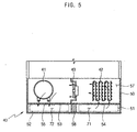
- the interior of the machine room casing 50 is partitioned into front and rear chambers 56 and 57 by a noise buffering plate 53 having a plurality of vent holes 54 and 55.
- the compressor 41, the condenser 42 and the cooling fan 43 are installed in the rear chamber 57, while the main intake vent 51 and the main exhaust vent 52 are located side-by-side at the upper surface of the front chamber 56.
- a partition plate 58 is positioned in the front chamber 56 of the machine room casing 50 so as to divide the front chamber 56 into a front intake chamber 71 communicating with the main intake vent 51 and a front exhaust chamber 72 communicating with the main exhaust vent 52.
- the noise buffering plate 53 allows air to circulate between the front and rear chambers 56 and 57 through the vent holes 54 and 55, but dampens the transmission of operational noise from both the compressor 41 and the cooling fan 43 to the main intake vent 51 or the main exhaust vent 52.
- the partition plate 58 divides the interior of the front chamber 56, thus preventing a mixing of intake air with exhaust air.
- the vent holes 54 and 55 are formed through the noise buffering plate 53 such that a group of vent holes 54 or 55 are formed at each side of the noise buffering plate 53 so as to correspond to each of the main intake vent 51 and the main exhaust vent 52.
- the condenser 42, the cooling fan 43 and the compressor 41 are sequentially arranged in the rear chamber 57 of the machine room 40 in a direction from a position around the main intake vent 51 to another position around the main exhaust vent 52. Due to the sequential arrangement of the condenser 42, the cooling fan 43 and the compressor 41 in the rear chamber 57 of the machine room 40, the inlet air primarily cools the condenser 42, and then flows to the compressor 41. The air is exhausted from the machine room 40, after cooling the compressor 41.
- a sub- intake vent 61 and a sub- exhaust vent 62 are respectively provided at both side edges of the upper surface of the machine room casing 50 to accomplish an auxiliary circulation of air through the machine room 40.
- the air also circulates through the machine room 40 by way of the sub-intake vent 61 and the sub- exhaust vent 62, in addition to the main intake vent 51 and the main exhaust vent 52, thus more effectively cooling the machine room 40.
- the refrigerator Since the main intake vent 51 and the main exhaust vent 52 are located side-by-side at the upper surface of the machine room casing 50, the refrigerator has a pleasant front appearance.
- the machine room casing 50 having the main intake vent 51 and the main exhaust vent 52 at the upper surface thereof, transmits the operational noise from both the compressor 41 and the cooling fan 43 in the machine room 40 to the atmosphere outside the upper surface of the machine room casing 50.
- the refrigerator thus restrains the operational noise transmitted to users in front of the refrigerator. In such a case, the transmission of the operational noise from both the compressor 41 and the cooling fan 43 in the machine room 40 to the outside of the upper surface of the machine room 40 is attenuated by the noise buffering plate 53, so that the operational noise transmitted to the outside of the refrigerator is remarkably reduced.
- the air to cool the machine room 40 having the above-described construction circulates as follows.
- the air is primarily drawn into the front chamber 56 of the machine room 40 through the main intake vent 51 formed at the upper surface of the front intake chamber 71 of the machine room 40, in response to the operation of the cooling fan 43.
- the inlet air then flows from the front intake chamber 71 into the rear chamber 57 of the machine room 40 through the vent holes 54 of the noise buffering plate 53.
- the air sequentially cools the condenser 42 and the compressor 41, and is the discharged into the front exhaust chamber 72 through the vent holes 55 of the noise buffering plate 53.
- the air is then discharged from the front exhaust chamber 72 of the machine room 40 to the atmosphere through the main exhaust vent 52.
- the partition plate 58 prevents a mixing of the intake air flowing from the main intake vent 51 with the exhaust air flow to the main exhaust vent 52.
- the auxiliary circulation of a small amount of air is accomplished through the sub-intake and sub- exhaust vents 61 and 62, thus enhancing the machine room cooling effect.
- the air circulation to cool the machine room 40 of the refrigerator according to the present invention is accomplished through the main intake and exhaust vents 51 and 52 formed at the upper surface of the machine room 40. The circulation of the air through the machine room 40 is thus effectively performed, even when the refrigerator is installed to stand between the walls 100 of the building, as shown in FIG. 1.
- preferred embodiments of the present invention provide a refrigerator in which a main intake vent and a main exhaust vent that circulate air through a machine room are located side-by-side at an upper surface of the machine room.
- the main intake and exhaust vents are not visible to users, and the refrigerator has a pleasant front appearance.
- the refrigerator since a transmission of operational noise from both a compressor and a cooling fan in the machine room to the atmosphere is attenuated by a noise buffering plate, the refrigerator remarkably reduces the operational noise transmitted to the atmosphere. Due to the main intake and exhaust vents formed at the upper surface of the machine room, the refrigerator restrains the operational noise transmitted to users in front of the refrigerator, and performs a silent operation which does not upset the users.
Landscapes
- Engineering & Computer Science (AREA)
- Chemical & Material Sciences (AREA)
- Combustion & Propulsion (AREA)
- Physics & Mathematics (AREA)
- Mechanical Engineering (AREA)
- Thermal Sciences (AREA)
- General Engineering & Computer Science (AREA)
- Cold Air Circulating Systems And Constructional Details In Refrigerators (AREA)
- Devices That Are Associated With Refrigeration Equipment (AREA)
Abstract
Description
Claims (19)
- A refrigerator, comprising:a cabinet (10) defining a storage compartment therein; a machine room (40) defined at a top of the cabinet (10);a main intake vent (51), located at an upper surface of the machine room (40); anda main exhaust vent (52), located at an upper surface of the machine room (40), wherein;the main intake vent (51) and the main exhaust vent (52) are located so as to allow air to circulate through the machine room (40).
- The refrigerator according to claim 1, wherein the machine room (40) further comprises:a compressor (41);a condenser (42); anda cool air circulation fan (43), wherein;the main intake vent (51), the condenser (42), the cool air circulation fan (43), the compressor (41), and the main exhaust vent (52) are positioned sequentially along an air flow path.
- The refrigerator according to claim 1 or claim 2, wherein the machine room (40) is horizontally and longitudinally defined along a front portion of the top of the cabinet (10), with the main intake vent (52) and the main exhaust vent (52) provided side-by-side at the upper surface of the machine room (40).
- The refrigerator according to claim 2, wherein the machine room (40) further comprises:a noise buffering plate (53), to divide the machine room (40) into a front chamber (56) and a rear chamber (57);the noise buffering plate (53) having a plurality of vent holes (54,55) to allow air flow between the front chamber (56) and the rear chamber (57).
- The refrigerator according to claim 4, wherein the vent holes (54,55) are formed through the noise buffering plate (53) such that groups of the vent holes (54,55) are formed respectively at each side of the noise buffering plate (53) so as to correspond to the main intake vent (51) and the main exhaust vent (52).
- The refrigerator according to claim 4 or claim 5, wherein the front chamber (56) further comprises a partition plate (58) to divide the front chamber (56) into a front intake chamber (71) and a front exhaust chamber (72).
- The refrigerator according to claim 6, wherein;the main intake vent (51) is located over the front intake chamber (71), andthe main exhaust vent (52) is located over the front exhaust chamber (72).
- The refrigerator according to any one of claims 4-7, wherein the condenser (42), the cooling fan (43) and the compressor (41) are sequentially arranged in the rear chamber (57) of the machine room (40) with the condenser (42) being proximate to the main intake vent (51), and the compressor (41) being proximate to the main exhaust vent (52).
- The refrigerator according to claim 7, wherein the main intake vent (51), the front intake chamber (71), a first set of the vent holes, the condenser, the cool air circulation fan, the compressor, a second set of the vent holes, the front exhaust chamber (72), and the main exhaust vent (51) are positioned sequentially along an air flow path.
- The refrigerator according to any preceding claim, further comprising a sub-intake vent (61) and a sub-exhaust vent (62) respectively provided at both side edges of the upper surface of the machine room (40) to accomplish an auxiliary circulation of air through the machine room (40).
- A refrigerator, comprising:a cabinet (10) defining a storage compartment therein; a machine room (40) defined at a top of the cabinet (10), comprising:a compressor (41);a condenser (42);a cool air circulation fan (43); anda noise buffering plate (53), to partition the machine room (40) into a front chamber (56) and a rear chamber (57), the noise buffering plate (53) having a plurality of vent holes (54,55) to allow air flow between the front chamber (56) and the rear chamber (57) ;a partition plate (58), dividing the front chamber (56) into a front intake chamber (71) and a front exhaust chamber (72);a main intake vent (51), located at an upper surface of the front intake chamber (71);a main exhaust vent (52), located at an upper surface of the front exhaust chamber (72); anda sub-intake vent (61) and a sub-exhaust vent (62) respectively provided at both side edges of the upper surface of the machine room (40) to accomplish an auxiliary circulation of air through the machine room (40).
- The refrigerator according to claim 11, wherein the vent holes (54,55) are arranged into a first vent hole group (54) and a second vent hole group (55);the first vent hole group (54) being positioned between the front intake chamber (71) and the rear chamber (57); andthe second vent hole group (55) being positioned between the front exhaust chamber (72) and the rear chamber (57).
- The refrigerator according to claim 12, wherein, by the force of the cool air circulation fan (43), cooling air;is drawn through the main intake vent (51) into the front intake chamber (71);passes through the noise buffering plate (53) by way of the first vent hole group (54) and into the rear chamber (57);cools the condenser (42);passes through the cool air circulation fan (43);cools the compressor (41);passes through the noise buffering plate (53) by way of the second vent hole (55) group and into the front exhaust chamber (72); andexits the machine room (40) by way of the main exhaust vent (52).
- A refrigerator, comprising:a cabinet (10) defining a storage compartment therein; anda machine room (40), comprising;a compressor (41);a condenser (42);a cool air circulation fan (43); anda noise buffering plate (53);the noise buffering plate (53) positioned in the machine room (46) so as to dampen operational noise from the compressor (41), condenser (42), and cool air circulation fan (43).
- The refrigerator according to claim 14, wherein the noise buffering plate (53) further comprises a plurality of vent holes (54,55) to allow air circulation in the machine room (40).
- The refrigerator of claim 15 or claim 16, further comprising a main intake vent (51) and a main exhaust vent (52) located so as to allow air to circulate through the machine room (40).
- The refrigerator according to any one of claims 14-16, wherein the noise buffering plate (53) is positioned to divide the machine room (40) into a front chamber (56) and a rear chamber (57).
- The refrigerator according to claim 16, wherein the compressor (41), the condenser (42), and the cool air circulation fan (43) are separated from the main intake vent (51) and the main exhaust vent (52) by the noise buffering plate (53), so as to limit operational noise transmission to an outside of the cabinet (10).
- The refrigerator of claim 16, wherein the main intake vent (51) and the main exhaust vent (52) are located on an upper side of the cabinet (10) so as to give the refrigerator a pleasant front appearance.
Applications Claiming Priority (2)
| Application Number | Priority Date | Filing Date | Title |
|---|---|---|---|
| KR2003010888 | 2003-02-21 | ||
| KR10-2003-0010888A KR100512677B1 (en) | 2003-02-21 | 2003-02-21 | Refrigerator |
Publications (2)
| Publication Number | Publication Date |
|---|---|
| EP1450120A2 true EP1450120A2 (en) | 2004-08-25 |
| EP1450120A3 EP1450120A3 (en) | 2004-09-22 |
Family
ID=32733150
Family Applications (1)
| Application Number | Title | Priority Date | Filing Date |
|---|---|---|---|
| EP03256772A Withdrawn EP1450120A3 (en) | 2003-02-21 | 2003-10-27 | Air circulation structure for a refrigerator machine room |
Country Status (4)
| Country | Link |
|---|---|
| US (1) | US7114345B2 (en) |
| EP (1) | EP1450120A3 (en) |
| KR (1) | KR100512677B1 (en) |
| CN (1) | CN1316215C (en) |
Cited By (3)
| Publication number | Priority date | Publication date | Assignee | Title |
|---|---|---|---|---|
| WO2009013121A3 (en) * | 2007-07-24 | 2009-05-28 | Bsh Bosch Siemens Hausgeraete | Refrigerator |
| WO2012097948A3 (en) * | 2011-01-17 | 2013-02-21 | BSH Bosch und Siemens Hausgeräte GmbH | Refrigerator and method for producing a refrigerator |
| EP3842720A1 (en) * | 2019-12-24 | 2021-06-30 | LG Electronics, Inc. | Refrigerator |
Families Citing this family (46)
| Publication number | Priority date | Publication date | Assignee | Title |
|---|---|---|---|---|
| US7185509B2 (en) | 2002-08-31 | 2007-03-06 | Samsung Electronics Co., Ltd. | Refrigerator |
| US20040041503A1 (en) * | 2002-08-31 | 2004-03-04 | Samsung Electronics Co., Ltd. | Frame of a wall-embedded refrigerator |
| EP1394488B1 (en) * | 2002-08-31 | 2008-09-17 | Samsung Electronics Co., Ltd. | Cabinet for recessed refrigerators and method for its assembly |
| US7188490B2 (en) | 2003-01-17 | 2007-03-13 | Samsung Electronics Co., Ltd. | Refrigerator |
| KR100557099B1 (en) * | 2003-12-09 | 2006-03-03 | 엘지전자 주식회사 | Heat Sink of Built-in Refrigerator |
| KR20050096341A (en) * | 2004-03-30 | 2005-10-06 | 삼성전자주식회사 | Built-in type refrigerator |
| US20070042698A1 (en) * | 2005-08-18 | 2007-02-22 | Jeffrey Negley | Venting system and related method for a vehicle refrigerator |
| KR101106643B1 (en) * | 2005-11-22 | 2012-01-18 | 삼성전자주식회사 | Refrigerator |
| KR100688656B1 (en) * | 2005-11-28 | 2007-03-02 | 엘지전자 주식회사 | Oil Supply Structure of Scroll Compressor |
| KR100751152B1 (en) * | 2005-11-30 | 2007-08-22 | 엘지전자 주식회사 | Oil Supply Structure of Scroll Compressor |
| KR100772219B1 (en) | 2005-12-12 | 2007-11-01 | 엘지전자 주식회사 | Oil Supply Structure of Scroll Compressor |
| KR100686747B1 (en) * | 2005-12-20 | 2007-02-26 | 엘지전자 주식회사 | Scroll compressor |
| KR100738708B1 (en) * | 2005-12-29 | 2007-07-12 | 엘지전자 주식회사 | Anti-vibration device of scroll compressor |
| KR101192198B1 (en) * | 2005-12-30 | 2012-10-17 | 엘지전자 주식회사 | Apparatus for reducing foaming of scroll compressor |
| EP1923571B1 (en) * | 2006-11-20 | 2015-10-14 | LG Electronics Inc. | Capacity-variable rotary compressor |
| EP2113053B1 (en) * | 2007-01-15 | 2015-08-19 | LG Electronics Inc. | Compressor and oil separating device therefor |
| EP2115302B1 (en) * | 2007-01-19 | 2016-03-16 | LG Electronics Inc. | Compressor and oil blocking device therefor |
| KR100869929B1 (en) * | 2007-02-23 | 2008-11-24 | 엘지전자 주식회사 | Scroll compressor |
| KR100867623B1 (en) * | 2007-03-21 | 2008-11-10 | 엘지전자 주식회사 | Compressor Vibration Reduction Device |
| KR100882481B1 (en) * | 2007-04-25 | 2009-02-06 | 엘지전자 주식회사 | Oil Supply Structure of Scroll Compressor |
| KR101387489B1 (en) * | 2007-07-11 | 2014-04-21 | 엘지전자 주식회사 | Refrigerator |
| KR20090032733A (en) * | 2007-09-28 | 2009-04-01 | 엘지전자 주식회사 | Radiator of refrigerator |
| KR101578002B1 (en) * | 2008-12-10 | 2015-12-16 | 엘지전자 주식회사 | Refrigerator |
| KR101565387B1 (en) * | 2008-12-10 | 2015-11-03 | 엘지전자 주식회사 | Refrigerator |
| KR101559787B1 (en) * | 2009-01-21 | 2015-10-13 | 엘지전자 주식회사 | Refrigerator |
| KR101578003B1 (en) * | 2009-01-21 | 2015-12-16 | 엘지전자 주식회사 | Refrigerator |
| KR101520704B1 (en) * | 2009-01-21 | 2015-05-15 | 엘지전자 주식회사 | Refrigerator |
| KR101559786B1 (en) * | 2009-01-21 | 2015-10-13 | 엘지전자 주식회사 | Refrigerator |
| KR101565404B1 (en) * | 2009-01-30 | 2015-11-03 | 엘지전자 주식회사 | A refrigerator |
| KR101559788B1 (en) * | 2009-01-30 | 2015-10-13 | 엘지전자 주식회사 | A refrigerator |
| KR20110019074A (en) * | 2009-08-19 | 2011-02-25 | 엘지전자 주식회사 | A refrigerator |
| DE102009056426A1 (en) * | 2009-09-03 | 2011-03-10 | Liebherr-Hausgeräte Ochsenhausen GmbH | Sub-assembly element for a refrigerator and / or freezer, refrigerator and / or freezer and method for mounting a refrigerator and / or freezer |
| CN102213515A (en) * | 2011-05-31 | 2011-10-12 | 合肥美的荣事达电冰箱有限公司 | Refrigerator body and refrigerator |
| CN102589237B (en) * | 2012-02-24 | 2016-11-23 | 海尔集团公司 | Refrigerator |
| US20130255305A1 (en) * | 2012-03-28 | 2013-10-03 | Brian S. Kim | Air duct device for refrigerator |
| KR102103951B1 (en) * | 2012-07-06 | 2020-04-24 | 삼성전자주식회사 | Refrigerator |
| WO2016174148A2 (en) * | 2015-04-29 | 2016-11-03 | BSH Hausgeräte GmbH | Home appliance device |
| US10126039B2 (en) | 2015-12-29 | 2018-11-13 | Whirlpool Corporation | Refrigeration appliance having side air intake vent with sound dampening |
| US11079171B2 (en) * | 2016-10-26 | 2021-08-03 | Whirlpool Corporation | Refrigerator with surround illumination feature |
| US10451297B2 (en) * | 2017-05-01 | 2019-10-22 | Haier Us Appliance Solutions, Inc. | Air conditioning system including a reheat loop |
| KR200486034Y1 (en) | 2017-07-20 | 2018-03-26 | 고민석 | Tooth development period with dropout preventing means |
| US11435093B2 (en) * | 2017-12-26 | 2022-09-06 | Gree Electric Appliances (Wuhan) Co., Ltd. | Air-conditioning outdoor device and air conditioner unit |
| CN108759243A (en) * | 2018-06-19 | 2018-11-06 | 青岛海尔股份有限公司 | Control oxygen fresh-keeping refrigerator |
| US11378325B2 (en) * | 2019-07-12 | 2022-07-05 | Thetford Bv | Refrigerator with noise reduction |
| WO2022263840A1 (en) * | 2021-06-18 | 2022-12-22 | Hubl Logistics Ltd | Transport pods |
| CN116792993B (en) * | 2023-06-07 | 2025-09-16 | 珠海格力电器股份有限公司 | Mobile fresh-keeping equipment and control method thereof |
Family Cites Families (12)
| Publication number | Priority date | Publication date | Assignee | Title |
|---|---|---|---|---|
| DE721839C (en) | 1939-06-21 | 1942-06-19 | Siemens Ag | Device for attenuating the noises emitted by compression refrigeration machines |
| US3736768A (en) * | 1971-06-29 | 1973-06-05 | Westinghouse Electric Corp | Machine compartment arrangement for a refrigerating device |
| US3712078A (en) * | 1971-11-22 | 1973-01-23 | Krispin Eng Ltd | Refrigeration unit |
| US4776182A (en) * | 1985-12-04 | 1988-10-11 | Gidseg Edward D | Circulating air refrigerator and power module for same |
| JPH02103366A (en) * | 1988-10-11 | 1990-04-16 | Toshiba Corp | Muffling device for cooling device |
| US5199273A (en) * | 1990-09-28 | 1993-04-06 | The Manitowoc Company, Inc. | Reach-in cooler with interchangeable refrigerator and freezer systems |
| US5729997A (en) * | 1996-02-29 | 1998-03-24 | General Electric Company | Refrigerator air circulation system |
| US5881567A (en) * | 1997-09-29 | 1999-03-16 | Whirlpool Corporation | Refrigerator condenser air flow |
| DE19746962A1 (en) | 1997-10-24 | 1999-04-29 | Aeg Hausgeraete Gmbh | Cooling or freezing apparatus |
| JP3945037B2 (en) * | 1998-09-04 | 2007-07-18 | 松下電器産業株式会社 | Photoelectric conversion element and manufacturing method thereof |
| US6094934A (en) * | 1998-10-07 | 2000-08-01 | Carrier Corporation | Freezer |
| JP3394475B2 (en) * | 1999-09-08 | 2003-04-07 | 松下冷機株式会社 | Cool box |
-
2003
- 2003-02-21 KR KR10-2003-0010888A patent/KR100512677B1/en not_active Expired - Lifetime
- 2003-10-23 US US10/690,500 patent/US7114345B2/en not_active Expired - Lifetime
- 2003-10-27 EP EP03256772A patent/EP1450120A3/en not_active Withdrawn
- 2003-10-27 CN CNB200310104381XA patent/CN1316215C/en not_active Expired - Fee Related
Cited By (4)
| Publication number | Priority date | Publication date | Assignee | Title |
|---|---|---|---|---|
| WO2009013121A3 (en) * | 2007-07-24 | 2009-05-28 | Bsh Bosch Siemens Hausgeraete | Refrigerator |
| WO2012097948A3 (en) * | 2011-01-17 | 2013-02-21 | BSH Bosch und Siemens Hausgeräte GmbH | Refrigerator and method for producing a refrigerator |
| EP3842720A1 (en) * | 2019-12-24 | 2021-06-30 | LG Electronics, Inc. | Refrigerator |
| US11587545B2 (en) | 2019-12-24 | 2023-02-21 | Lg Electronics Inc. | Refrigerator with compressor noise reduction |
Also Published As
| Publication number | Publication date |
|---|---|
| US7114345B2 (en) | 2006-10-03 |
| KR100512677B1 (en) | 2005-09-07 |
| EP1450120A3 (en) | 2004-09-22 |
| KR20040075410A (en) | 2004-08-30 |
| CN1523315A (en) | 2004-08-25 |
| US20040163408A1 (en) | 2004-08-26 |
| CN1316215C (en) | 2007-05-16 |
Similar Documents
| Publication | Publication Date | Title |
|---|---|---|
| US7114345B2 (en) | Air circulation structure for a refrigerator machine room | |
| US6735976B2 (en) | Refrigerator | |
| KR101390448B1 (en) | Refrigerator | |
| CN1236261C (en) | Electric refrigerator | |
| US6666045B1 (en) | Kimchi refrigerator | |
| EP1443289A1 (en) | Refrigerator | |
| KR20090046297A (en) | Food storage device | |
| KR20090006418A (en) | Refrigerator | |
| TW201035508A (en) | Electric refrigerator | |
| KR102942097B1 (en) | Refrigerator | |
| CN100572996C (en) | Refrigerator with a door | |
| JP2003075048A (en) | Electric refrigerator | |
| KR100528289B1 (en) | Refrigerator | |
| KR100926763B1 (en) | Refrigerator | |
| JP2004278878A (en) | refrigerator | |
| JP2002295953A (en) | Refrigerator | |
| JP3599984B2 (en) | refrigerator | |
| JPH09280717A (en) | Refrigerating storage | |
| JPH0914827A (en) | Cooling and storing device | |
| KR100436274B1 (en) | Refrigerator | |
| JP2001280803A (en) | Refrigerator | |
| JP2001349656A (en) | Refrigerator | |
| KR101483591B1 (en) | Refrigerator | |
| JPH07167545A (en) | Cold air passage in refrigerator | |
| KR20040066340A (en) | Refrigerator |
Legal Events
| Date | Code | Title | Description |
|---|---|---|---|
| PUAI | Public reference made under article 153(3) epc to a published international application that has entered the european phase |
Free format text: ORIGINAL CODE: 0009012 |
|
| PUAL | Search report despatched |
Free format text: ORIGINAL CODE: 0009013 |
|
| AK | Designated contracting states |
Kind code of ref document: A2 Designated state(s): AT BE BG CH CY CZ DE DK EE ES FI FR GB GR HU IE IT LI LU MC NL PT RO SE SI SK TR |
|
| AX | Request for extension of the european patent |
Extension state: AL LT LV MK |
|
| AK | Designated contracting states |
Kind code of ref document: A3 Designated state(s): AT BE BG CH CY CZ DE DK EE ES FI FR GB GR HU IE IT LI LU MC NL PT RO SE SI SK TR |
|
| AX | Request for extension of the european patent |
Extension state: AL LT LV MK |
|
| 17P | Request for examination filed |
Effective date: 20050202 |
|
| AKX | Designation fees paid |
Designated state(s): DE FR GB |
|
| STAA | Information on the status of an ep patent application or granted ep patent |
Free format text: STATUS: THE APPLICATION IS DEEMED TO BE WITHDRAWN |
|
| 18D | Application deemed to be withdrawn |
Effective date: 20090505 |