EP1450039A1 - Engine controller - Google Patents
Engine controller Download PDFInfo
- Publication number
- EP1450039A1 EP1450039A1 EP02785997A EP02785997A EP1450039A1 EP 1450039 A1 EP1450039 A1 EP 1450039A1 EP 02785997 A EP02785997 A EP 02785997A EP 02785997 A EP02785997 A EP 02785997A EP 1450039 A1 EP1450039 A1 EP 1450039A1
- Authority
- EP
- European Patent Office
- Prior art keywords
- engine
- engine speed
- ignition timing
- idling
- detecting means
- Prior art date
- Legal status (The legal status is an assumption and is not a legal conclusion. Google has not performed a legal analysis and makes no representation as to the accuracy of the status listed.)
- Withdrawn
Links
- 230000010354 integration Effects 0.000 claims abstract description 46
- 230000008859 change Effects 0.000 claims abstract description 22
- 230000000979 retarding effect Effects 0.000 claims abstract description 17
- 230000005540 biological transmission Effects 0.000 claims description 5
- 239000000498 cooling water Substances 0.000 abstract description 33
- 238000013459 approach Methods 0.000 abstract description 4
- 239000000446 fuel Substances 0.000 description 138
- 238000002347 injection Methods 0.000 description 81
- 239000007924 injection Substances 0.000 description 81
- 238000000034 method Methods 0.000 description 63
- 230000008569 process Effects 0.000 description 61
- 238000001514 detection method Methods 0.000 description 49
- 230000006835 compression Effects 0.000 description 24
- 238000007906 compression Methods 0.000 description 24
- 238000004880 explosion Methods 0.000 description 17
- 230000001133 acceleration Effects 0.000 description 9
- 238000010586 diagram Methods 0.000 description 6
- 230000004043 responsiveness Effects 0.000 description 6
- 230000001052 transient effect Effects 0.000 description 6
- 239000002360 explosive Substances 0.000 description 4
- 238000012546 transfer Methods 0.000 description 4
- 238000004891 communication Methods 0.000 description 3
- 239000010687 lubricating oil Substances 0.000 description 3
- 230000000630 rising effect Effects 0.000 description 3
- 238000004088 simulation Methods 0.000 description 3
- 238000006073 displacement reaction Methods 0.000 description 2
- 238000005259 measurement Methods 0.000 description 2
- 230000007704 transition Effects 0.000 description 2
- 238000002485 combustion reaction Methods 0.000 description 1
- 238000007796 conventional method Methods 0.000 description 1
- 230000003111 delayed effect Effects 0.000 description 1
- 230000000694 effects Effects 0.000 description 1
- 238000002474 experimental method Methods 0.000 description 1
- 239000002828 fuel tank Substances 0.000 description 1
- 239000003502 gasoline Substances 0.000 description 1
- 238000004519 manufacturing process Methods 0.000 description 1
- 238000000746 purification Methods 0.000 description 1
- 230000009467 reduction Effects 0.000 description 1
- 230000004044 response Effects 0.000 description 1
Images









Classifications
-
- F—MECHANICAL ENGINEERING; LIGHTING; HEATING; WEAPONS; BLASTING
- F02—COMBUSTION ENGINES; HOT-GAS OR COMBUSTION-PRODUCT ENGINE PLANTS
- F02D—CONTROLLING COMBUSTION ENGINES
- F02D41/00—Electrical control of supply of combustible mixture or its constituents
- F02D41/02—Circuit arrangements for generating control signals
- F02D41/14—Introducing closed-loop corrections
- F02D41/1401—Introducing closed-loop corrections characterised by the control or regulation method
- F02D41/1402—Adaptive control
-
- F—MECHANICAL ENGINEERING; LIGHTING; HEATING; WEAPONS; BLASTING
- F02—COMBUSTION ENGINES; HOT-GAS OR COMBUSTION-PRODUCT ENGINE PLANTS
- F02D—CONTROLLING COMBUSTION ENGINES
- F02D31/00—Use of speed-sensing governors to control combustion engines, not otherwise provided for
- F02D31/001—Electric control of rotation speed
-
- F—MECHANICAL ENGINEERING; LIGHTING; HEATING; WEAPONS; BLASTING
- F02—COMBUSTION ENGINES; HOT-GAS OR COMBUSTION-PRODUCT ENGINE PLANTS
- F02D—CONTROLLING COMBUSTION ENGINES
- F02D41/00—Electrical control of supply of combustible mixture or its constituents
- F02D41/02—Circuit arrangements for generating control signals
- F02D41/04—Introducing corrections for particular operating conditions
- F02D41/06—Introducing corrections for particular operating conditions for engine starting or warming up
- F02D41/062—Introducing corrections for particular operating conditions for engine starting or warming up for starting
- F02D41/064—Introducing corrections for particular operating conditions for engine starting or warming up for starting at cold start
-
- F—MECHANICAL ENGINEERING; LIGHTING; HEATING; WEAPONS; BLASTING
- F02—COMBUSTION ENGINES; HOT-GAS OR COMBUSTION-PRODUCT ENGINE PLANTS
- F02D—CONTROLLING COMBUSTION ENGINES
- F02D41/00—Electrical control of supply of combustible mixture or its constituents
- F02D41/02—Circuit arrangements for generating control signals
- F02D41/04—Introducing corrections for particular operating conditions
- F02D41/08—Introducing corrections for particular operating conditions for idling
- F02D41/086—Introducing corrections for particular operating conditions for idling taking into account the temperature of the engine
-
- F—MECHANICAL ENGINEERING; LIGHTING; HEATING; WEAPONS; BLASTING
- F02—COMBUSTION ENGINES; HOT-GAS OR COMBUSTION-PRODUCT ENGINE PLANTS
- F02D—CONTROLLING COMBUSTION ENGINES
- F02D41/00—Electrical control of supply of combustible mixture or its constituents
- F02D41/02—Circuit arrangements for generating control signals
- F02D41/18—Circuit arrangements for generating control signals by measuring intake air flow
- F02D41/182—Circuit arrangements for generating control signals by measuring intake air flow for the control of a fuel injection device
-
- F—MECHANICAL ENGINEERING; LIGHTING; HEATING; WEAPONS; BLASTING
- F02—COMBUSTION ENGINES; HOT-GAS OR COMBUSTION-PRODUCT ENGINE PLANTS
- F02P—IGNITION, OTHER THAN COMPRESSION IGNITION, FOR INTERNAL-COMBUSTION ENGINES; TESTING OF IGNITION TIMING IN COMPRESSION-IGNITION ENGINES
- F02P5/00—Advancing or retarding ignition; Control therefor
- F02P5/04—Advancing or retarding ignition; Control therefor automatically, as a function of the working conditions of the engine or vehicle or of the atmospheric conditions
- F02P5/145—Advancing or retarding ignition; Control therefor automatically, as a function of the working conditions of the engine or vehicle or of the atmospheric conditions using electrical means
- F02P5/15—Digital data processing
- F02P5/1502—Digital data processing using one central computing unit
- F02P5/1506—Digital data processing using one central computing unit with particular means during starting
-
- F—MECHANICAL ENGINEERING; LIGHTING; HEATING; WEAPONS; BLASTING
- F02—COMBUSTION ENGINES; HOT-GAS OR COMBUSTION-PRODUCT ENGINE PLANTS
- F02P—IGNITION, OTHER THAN COMPRESSION IGNITION, FOR INTERNAL-COMBUSTION ENGINES; TESTING OF IGNITION TIMING IN COMPRESSION-IGNITION ENGINES
- F02P5/00—Advancing or retarding ignition; Control therefor
- F02P5/04—Advancing or retarding ignition; Control therefor automatically, as a function of the working conditions of the engine or vehicle or of the atmospheric conditions
- F02P5/145—Advancing or retarding ignition; Control therefor automatically, as a function of the working conditions of the engine or vehicle or of the atmospheric conditions using electrical means
- F02P5/15—Digital data processing
- F02P5/1502—Digital data processing using one central computing unit
- F02P5/1508—Digital data processing using one central computing unit with particular means during idling
-
- F—MECHANICAL ENGINEERING; LIGHTING; HEATING; WEAPONS; BLASTING
- F02—COMBUSTION ENGINES; HOT-GAS OR COMBUSTION-PRODUCT ENGINE PLANTS
- F02P—IGNITION, OTHER THAN COMPRESSION IGNITION, FOR INTERNAL-COMBUSTION ENGINES; TESTING OF IGNITION TIMING IN COMPRESSION-IGNITION ENGINES
- F02P9/00—Electric spark ignition control, not otherwise provided for
- F02P9/002—Control of spark intensity, intensifying, lengthening, suppression
- F02P9/005—Control of spark intensity, intensifying, lengthening, suppression by weakening or suppression of sparks to limit the engine speed
-
- F—MECHANICAL ENGINEERING; LIGHTING; HEATING; WEAPONS; BLASTING
- F02—COMBUSTION ENGINES; HOT-GAS OR COMBUSTION-PRODUCT ENGINE PLANTS
- F02D—CONTROLLING COMBUSTION ENGINES
- F02D41/00—Electrical control of supply of combustible mixture or its constituents
- F02D41/02—Circuit arrangements for generating control signals
- F02D41/14—Introducing closed-loop corrections
- F02D41/1401—Introducing closed-loop corrections characterised by the control or regulation method
- F02D2041/1409—Introducing closed-loop corrections characterised by the control or regulation method using at least a proportional, integral or derivative controller
-
- F—MECHANICAL ENGINEERING; LIGHTING; HEATING; WEAPONS; BLASTING
- F02—COMBUSTION ENGINES; HOT-GAS OR COMBUSTION-PRODUCT ENGINE PLANTS
- F02D—CONTROLLING COMBUSTION ENGINES
- F02D41/00—Electrical control of supply of combustible mixture or its constituents
- F02D41/02—Circuit arrangements for generating control signals
- F02D41/14—Introducing closed-loop corrections
- F02D41/1401—Introducing closed-loop corrections characterised by the control or regulation method
- F02D2041/1413—Controller structures or design
- F02D2041/1422—Variable gain or coefficients
-
- F—MECHANICAL ENGINEERING; LIGHTING; HEATING; WEAPONS; BLASTING
- F02—COMBUSTION ENGINES; HOT-GAS OR COMBUSTION-PRODUCT ENGINE PLANTS
- F02D—CONTROLLING COMBUSTION ENGINES
- F02D2200/00—Input parameters for engine control
- F02D2200/02—Input parameters for engine control the parameters being related to the engine
- F02D2200/04—Engine intake system parameters
- F02D2200/0402—Engine intake system parameters the parameter being determined by using a model of the engine intake or its components
-
- F—MECHANICAL ENGINEERING; LIGHTING; HEATING; WEAPONS; BLASTING
- F02—COMBUSTION ENGINES; HOT-GAS OR COMBUSTION-PRODUCT ENGINE PLANTS
- F02D—CONTROLLING COMBUSTION ENGINES
- F02D2200/00—Input parameters for engine control
- F02D2200/02—Input parameters for engine control the parameters being related to the engine
- F02D2200/04—Engine intake system parameters
- F02D2200/0406—Intake manifold pressure
-
- F—MECHANICAL ENGINEERING; LIGHTING; HEATING; WEAPONS; BLASTING
- F02—COMBUSTION ENGINES; HOT-GAS OR COMBUSTION-PRODUCT ENGINE PLANTS
- F02D—CONTROLLING COMBUSTION ENGINES
- F02D2200/00—Input parameters for engine control
- F02D2200/02—Input parameters for engine control the parameters being related to the engine
- F02D2200/04—Engine intake system parameters
- F02D2200/0414—Air temperature
-
- F—MECHANICAL ENGINEERING; LIGHTING; HEATING; WEAPONS; BLASTING
- F02—COMBUSTION ENGINES; HOT-GAS OR COMBUSTION-PRODUCT ENGINE PLANTS
- F02D—CONTROLLING COMBUSTION ENGINES
- F02D41/00—Electrical control of supply of combustible mixture or its constituents
- F02D41/02—Circuit arrangements for generating control signals
- F02D41/14—Introducing closed-loop corrections
- F02D41/1438—Introducing closed-loop corrections using means for determining characteristics of the combustion gases; Sensors therefor
- F02D41/1444—Introducing closed-loop corrections using means for determining characteristics of the combustion gases; Sensors therefor characterised by the characteristics of the combustion gases
- F02D41/1454—Introducing closed-loop corrections using means for determining characteristics of the combustion gases; Sensors therefor characterised by the characteristics of the combustion gases the characteristics being an oxygen content or concentration or the air-fuel ratio
-
- Y—GENERAL TAGGING OF NEW TECHNOLOGICAL DEVELOPMENTS; GENERAL TAGGING OF CROSS-SECTIONAL TECHNOLOGIES SPANNING OVER SEVERAL SECTIONS OF THE IPC; TECHNICAL SUBJECTS COVERED BY FORMER USPC CROSS-REFERENCE ART COLLECTIONS [XRACs] AND DIGESTS
- Y02—TECHNOLOGIES OR APPLICATIONS FOR MITIGATION OR ADAPTATION AGAINST CLIMATE CHANGE
- Y02T—CLIMATE CHANGE MITIGATION TECHNOLOGIES RELATED TO TRANSPORTATION
- Y02T10/00—Road transport of goods or passengers
- Y02T10/10—Internal combustion engine [ICE] based vehicles
- Y02T10/40—Engine management systems
Definitions
- the present invention relates to an engine controller which controls an engine, and more particularly to an apparatus suitable for controlling an engine having a fuel injection apparatus which injects fuel.
- the fuel injection timing, the amount of injected fuel, i.e., the air-fuel ratio, and the like can be more easily controlled, so that a higher output power, smaller fuel consumption, exhaust gas purification, and the like can be enhanced.
- the fuel injection timing particularly, the state of an intake valve in a strict sense, or the phase state of a camshaft in a usual sense is detected, and fuel is usually injected in accordance with the detected state.
- a so-called cam sensor for detecting the phase state of a camshaft is expensive. In a two-wheeled vehicle, particularly, a cam sensor cannot be often employed because of a problem in that the size of a cylinder head is increased.
- JP-A-10-227252 proposes an engine controller in which the phase state of a crankshaft and the intake pressure are detected and the stroke state of a cylinder is detected from them.
- the stroke state can be detected without detecting the phase of a camshaft, and hence the fuel injection timing and the like can be controlled in accordance with the stroke state.
- the ignition timing affects the torque of an engine.
- the ignition timing is set to be slightly advanced from the compression top dead center, the highest torque is generated.
- the ignition timing is changed from it toward advance or retard, the torque is reduced.
- a specific ignition timing controlling technique for, in, for example, a state immediately after start of rotation of an engine, adequately controlling the unstable engine speed in an idling state is not proposed.
- the invention is developed in order to solve the problems discussed above, and has an objective of providing an engine controller which can adequately control the engine speed in an idling state immediately after engine start or the like.
- the engine controller of claim 1 of the invention is characterized in that the apparatus comprises: crankshaft phase detecting means for detecting a phase of a crankshaft; intake pressure detecting means for detecting an intake pressure of an intake passage of an engine; stroke detecting means for detecting a stroke of the engine on the basis of the phase of the crankshaft detected by the crankshaft phase detecting means, and the intake pressure detected by the intake pressure detecting means; and engine controlling means for controlling an operation state of the engine on the basis of the stroke of the engine detected by the stroke detecting means, and the engine controlling means comprises: engine speed detecting means for detecting a speed of the engine; idling detecting means for detecting an idling.state of the engine; target engine speed setting means for, when the idling state of the engine is detected by the idling detecting means, setting a target engine speed; and idling ignition timing setting means for, when the idling state of the engine is detected by the idling detecting means, setting an
- the engine controller of claim 2 of the invention is characterized in that, in the invention of claim 1, when the ignition timing is changed to one of an advancing side and a retarding side, the idling ignition timing setting means avoids continuation of a change of the ignition timing to a same side.
- the engine controller of claim 3 of the invention is characterized in that, in the invention of claim 1 or 2, the idling ignition timing setting means sets the ignition timing by multiplying an integration value of the difference between the target engine speed set by the target engine speed setting means and the engine speed detected by the engine speed detecting means, with a predetermined gain.
- the engine controller of claim 4 of the invention is characterized in that, in the invention of claim 3, when the ignition timing is changed to one of the advancing side and the retarding side, the idling ignition timing setting means sets the ignition timing change setting gain for the same side to a smaller value, the ignition timing change setting gain being to be multiplied with the integration value of the difference between the target engine speed set by the target engine speed setting means and the engine speed detected by the engine speed detecting means.
- the engine controller of claim 5 of the invention is characterized in that, in the invention of claim 3 or 4, immediately after start of rotation of the engine, the idling ignition timing setting means sets the gain to a larger value, the gain being to be multiplied with the integration value of the difference between the target engine speed set by the target engine speed setting means and the engine speed detected by the engine speed detecting means.
- the engine controller of claim 6 of the invention is characterized in that, in the invention of any one of claims 1 to 5, the apparatus further comprises engine temperature detecting means for detecting a temperature of the engine, and the idling ignition timing setting means sets the ignition timing at a state change of the engine from a state other than the idling state to the idling state, on the basis of the engine temperature detected by the engine temperature detecting means.
- the engine controller of claim 7 of the invention is characterized in that, in the invention of any one of claims 1 to 6, the apparatus further comprises engine temperature detecting means for detecting a temperature of the engine, and the idling ignition timing setting means sets upper and lower limits of the ignition timing on the basis of the engine temperature detected by the engine temperature detecting means, and restricts the ignition timing by the upper and lower limits.
- the engine controller of claim 8 of the invention is characterized in that, in the invention of claim 7, the idling ignition timing setting means sets the upper and lower limits of the ignition timing so that a width between the upper and lower limits is narrower as the engine temperature detected by the engine temperature detecting means is higher.
- the engine controller of claim 9 of the invention is characterized in that, in the invention of any one of claims 1 to 8, the apparatus further comprises atmospheric pressure detecting means for detecting an atmospheric pressure, and the idling detecting means sets a predetermined value of the intake pressure for detecting the idling state, on the basis of the atmospheric pressure detected by the atmospheric pressure detecting means, and, when the intake pressure detected by the intake pressure detecting means is equal to or lower than the predetermined value for detecting the idling state when the phase of the crankshaft detected by the crankshaft phase detecting means has a predetermined value, detects the idling state of the engine.
- the engine controller of claim 10 of the invention is characterized in that, in the invention of claim 9, the idling detecting means sets the predetermined value of the intake pressure for detecting the idling state to be larger as the atmospheric pressure detected by the atmospheric pressure detecting means is higher.
- the engine controller of claim 11 of the invention is characterized in that, in the invention of claim 9 or 10, the atmospheric pressure detecting means detects the atmospheric pressure on the basis of the intake pressure detected by the intake pressure detecting means.
- the engine controller of claim 12 of the invention is characterized in that, in the invention of any one of claims 1 to 11, the apparatus further comprises a centrifugal clutch between the engine and a transmission, and, when the engine speed detected by the engine speed detecting means is equal to or lower than an engagement speed of the centrifugal clutch, the idling detecting means detects the idling state of the engine.
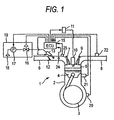
- Fig. 1 is a diagram showing the configuration of, for example, an engine for a motorcycle and an example of a control apparatus for the engine.
- the engine 1 is a single-cylinder four-cycle engine of a relatively small displacement, and comprises a cylinder body 2, a crankshaft 3, a piston 4, a combustion chamber 5, an intake pipe (intake passage) 6, an intake valve 7, an exhaust pipe 8, an exhaust valve 9, a spark plug 10, and an ignition coil 11.
- a throttle valve 12 which is opened or closed in accordance with the degree of an accelerator operation is disposed in the intake pipe 6, and an injector 13 serving as a fuel injection apparatus is disposed in the intake pipe 6 downstream from the throttle valve 12.
- the injector 13 is connected to a filter 18 which is disposed in a fuel tank 19, a fuel pump 17, and a pressure control valve 16.
- a centrifugal clutch is interposed between the engine 1 and a transmission.
- the operation state of the engine 1 is controlled by an engine control unit 15.
- the engine control unit 15 As control inputs of the engine control unit 15, i.e., means for detecting the operation state of the engine 1, the following sensors are disposed: a crank angle sensor 20 which detects the rotation angle or the phase of the crankshaft 3; a cooling water temperature sensor 21 which detects the temperature of the cylinder body 2 or the cooling water temperature, i.e., the temperature of the engine body; an exhaust air-fuel ratio sensor 22 which detects the air-fuel ratio in the exhaust pipe 8; an intake pressure sensor 24 which detects the intake pressure in the intake pipe 6; and an intake temperature sensor 25 which detects the temperature in the intake pipe 6, i.e., the intake temperature.
- the engine control unit 15 receives detection signals of these sensors, and outputs a control signal to the fuel pump 17, the pressure control valve 16, the injector 13, and the ignition coil 11.
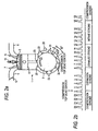
- a crank angle signal which is output from the crank angle sensor 20 will be described.
- a plurality of teeth 23 are protruded at substantially equal intervals from the outer circumference of the crankshaft 3, and the crank angle sensor 20 such as a magnetic sensor detects the approach of each tooth, applies an appropriate electric process, and then transmits pulse signals.
- the pitch of the teeth 23 in the circumferential direction is set to 30° in terms of the phase (rotation angle) of the crankshaft 3, and the width of each of the teeth 23 in the circumferential direction is set to 10° in terms of the phase (rotation angle) of the crankshaft 3. In one place only, however; the pitch is not set as described above, but set twice the pitch of the other teeth 23.
- toothless portion In the place, as indicated by the two-dot chain line in Fig. 2a, no tooth is formed in a portion where a tooth should originally exist, or special setting is applied. This portion corresponds to an unequal interval. Hereinafter, this portion is often referred to as toothless portion.
- Fig. 2a shows the state at the compression top dead center (also the state at the exhaust top dead center is identical in form).
- the pulse signals are numbered in the sequence that the pulse signal immediately before the compression top dead center is indicated by "0", the next pulse by "1", and the next next pulse by "2", and the last number is set to "4".
- the portion subsequent to the tooth 23 corresponding to the pulse signal of "4" is the toothless portion. Therefore, it is assumed that a tooth exists in the portion, and an extra count for one tooth is performed so that the pulse signal for the next tooth 23 is numbered "6".
- the toothless portion approaches the portion subsequent to the pulse signal of "16", and therefore an extra count for one tooth is performed in the same manner as described above so that the pulse signal for the next tooth 23 is numbered "18".
- the crankshaft 3 makes two rotations, all the cycles of the four strokes are completed.
- the pulse signal for the subsequent tooth 23 is again numbered "0".
- the portion immediately after the pulse signal of the "0"-numbered tooth 23 ought to correspond to the compression top dead center.
- the detected pulse signal train, or each single pulse signal is defined as a crank pulse.
- stroke detection is performed on the basis of the crank pulse as described later, a crank timing can be detected.
- the teeth 23 may be disposed on the outer periphery of a member which is rotated in synchronization with. the crankshaft 3. The alternative is strictly identical with the configuration described above.
- Fig. 3 is a block diagram showing an embodiment of an engine control computing process which is performed by the microcomputer in the engine control unit 15.
- the computing process comprises: an engine speed calculating section 26 which calculates the engine speed from the crank angle signal; a crank timing detecting section 27 which detects crank timing information, i.e., the stroke state from the crank angle signal and the intake pressure signal; a stroke detection permitting section 29 which reads the engine speed calculated by the engine speed calculating section 26, which outputs stroke detection permission information to the crank timing detecting section 27, and which fetches and outputs stroke detection information produced by the crank timing detecting section 27; a cylinder air mass calculating section 28 which reads the crank timing: information detected by the crank timing detecting section 27, and which calculates a cylinder air mass (intake air mass) from the intake temperature signal, the cooling water temperature (engine temperature) signal, the intake pressure signal, and the engine speed calculated by the engine speed calculating section 26; a target air-fuel ratio
- the engine speed calculating section 26 calculates the rotation speed of the crankshaft serving as an output shaft of the engine, as the engine speed. Specifically, an instantaneous value of the engine speed which is obtained by dividing the phase between the adjacent teeth 23 by a time required for detecting the corresponding crank pulse, and an average value of the engine speed consisting of the moving average value are calculated.
- the crank timing detecting section 27 is configured: in a similar manner as the stroke judging apparatus disclosed in JP-A-10-227252 described above.
- the stroke state of each cylinder is detected, and the detected state is output as the crank timing information.
- a crankshaft and a camshaft continue to be rotated at a predetermined phase difference.
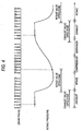
- crank pulse "9" 'or "21" which is a fourth pulse counted from the above-mentioned toothless portion is in either of the exhaust stroke or the compression stroke.
- the exhaust stroke as well known, the exhaust valve is opened, the intake valve is closed, and hence the intake pressure is high.
- crank pulse "21" which is at a timing of a low intake pressure indicates that the cylinder is in the compression stroke, and a timing immediately after crank pulse "0" is obtained corresponds to the compression top dead center.
- the stroke detection permitting section 29 outputs stroke detection permission information for the crank timing detecting section 27 in accordance with a computing process shown in Fig. 5.
- detection of a stroke from the crank pulse requires at least two rotations of the crankshaft. During this period, the crank pulse including the toothless portion must be stabilized. In a single-cylinder engine of a relatively small displacement as in the embodiment, however, the rotation state of the engine is not stabilized in a starting process or so-called cranking. Therefore, the rotation state of the engine is judged by the computing process of Fig. 5, and stroke detection is permitted.
- the computing process of Fig. 5 is executed with using, for example, an input of the crank pulse as a trigger.
- a step for communication is not particularly disposed in the flowchart, information which is obtained as a result of the computing process is updated and stored at any time into a storage apparatus, and information and programs which are necessary for the computing process are read out at any time from the storage apparatus.
- step S11 the average value of the engine speed calculated by the engine speed calculating section 26 is first read in step S11.
- step S12 the control proceeds to step S12 to judge whether or not the average value of the engine speed which is read in step S11 is equal to or larger than a preset stroke detection permitting predetermined speed that is equal to or larger than a rotation speed corresponding to the initial explosion. If the average value of the engine speed is equal to or larger than the stroke detection permitting predetermined speed, the control proceeds to step S13. If not, the control proceeds to step S14.
- step S13 information indicative of permitting of stroke detection is output, and the control then returns to a main program.
- step S14 information indicative of disabling of stroke detection is output, and the control then returns to the main program.
- stroke detection is permitted after the average value of the engine speed becomes equal to or larger than the stroke detection permitting predetermined rotation speed that is equal to or larger than at least the speed corresponding to the initial explosion. Therefore, the crank pulse is stabilized, and correct stroke detection can be performed.
- the cylinder air mass calculating section 28 has a three-dimensional map for calculating the cylinder air mass from the intake pressure signal and the engine speed calculated by the engine speed calculating section 26.
- the three-dimensional map of the cylinder air mass requires only measurement of the cylinder air mass when the intake pressure is changed while rotating the engine at a predetermined speed, and such measurement can be conducted by a relatively simple experiment. Therefore, the map can be easily produced.
- the map may be produced with using the simulator. Since the cylinder air mass is changed depending on the temperature of the engine, the mass may be corrected with using the cooling water temperature (engine temperature) signal.
- the target air-fuel ratio calculating section 33 has a three-dimensional map for calculating the target air-fuel ratio from the intake pressure signal and the engine speed calculated by the engine speed calculating section 26.
- the three-dimensional map can be theoretically set to some extent.
- the air-fuel ratio usually correlates with the torque. As the air-fuel ratio is smaller or the fuel is larger and the air is smaller, the torque is larger, and the efficiency is lower. By contrast, as the air-fuel ratio is larger or the fuel is smaller and the air is larger, the torque is smaller, and the efficiency is higher.
- a state of a small air-fuel ratio is called rich, and that of a large air-fuel ratio is called lean.
- the leanest state is at an air-fuel ratio which is called a so-called ideal air-fuel ratio or a stoichiometric ratio, and at which gasoline completely burns, i.e., an air-fuel ratio of 14.7.
- the engine speed is one of indices indicating the operation state of the engine.
- the air-fuel ratio is set to be large, and, in the low engine speed side, the ratio is set to be small. This is conducted in order to enhance the responsiveness of the torque in the low engine speed side, and to enhance the responsiveness of the rotation state in the high engine speed side.
- the intake pressure is one of indices indicating the engine load state such as the throttle opening.
- the air-fuel ratio is set to be small, and, in a state where the engine load is small, or the throttle opening is small and the intake pressure is low, the air-fuel ratio is set to be large. This is conducted in order to place emphasis on the torque in a state where the engine load is large, and to place emphasis on the efficiency in a state where the engine load is small.
- the target air-fuel ratio is a numerical value from which physical meanings can be easily grasped. In accordance with the required output characteristics of the engine, therefore, the target air-fuel ratio can be set to some extent. It is a matter of course that tuning can be conducted in accordance with the output characteristics of an actual vehicle.
- the target air-fuel ratio calculating section 33 has a transient correcting section 29 which detects transient of the operation state of the engine, specifically, the acceleration state or the deceleration state, from the intake pressure signal, and which corrects the target air-fuel ratio in accordance with the detected transient.
- the intake pressure can be deemed as a resulting phenomenon of a throttle operation. Therefore, it will be see that, when the intake pressure is raised, the throttle is opened and acceleration is requested, or the acceleration state is set.
- the target air-fuel ratio is temporarily set to the rich side in accordance with the detected state, and then returned to the original target air-fuel ratio.
- the return to the target air-fuel ratio may be realized by a known method such as that in which the weighting coefficient of a weighted average value of the air-fuel ratio which is set to the rich side in transient, and the original target air-fuel ratio is gradually changed.
- the target air-fuel ratio may be set to be leaner than the original target air-fuel ratio so as to place emphasis on the efficiency.
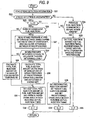
- the fuel injection amount calculating section 34 calculates the fuel injection amount and the fuel injection timing in engine start and usual operation, in accordance with a computing process shown in Fig. 9.
- the computing process of Fig. 9 is executed with using, for example, an input of the crank pulse as a trigger.
- a step for communication is not particularly disposed in the flowchart, information which is obtained as a result of the computing process is updated and stored at any time into the storage apparatus, and information and programs which are necessary for the computing process are read out at any time from the storage apparatus.
- the stroke detection information output from the stroke detection permitting section 29 is first read in step S21.
- step S22 the control proceeds to step S22 to judge whether the stroke detection by the crank timing detecting section 27 is uncompleted or not. If the stroke detection is uncompleted, the control proceeds to step S23. If not, the control proceeds to step S24.
- step S23 it is judged whether a fuel injection number counter n is "0" or not. If the fuel injection number counter n is "0", the control proceeds to step S25.
- step S25 it is judged whether the next fuel injection is third or subsequent fuel injection counted from the beginning of engine start or not. If the next fuel injection is third or subsequent fuel injection, the control proceeds to step S27. If not, the control proceeds to step S28.
- step S27 the intake pressure at a preset predetermined crank angle during two rotations of the crankshaft, in the embodiment, at crank pulse "6" or “8" in Figs. 2 and 4 is read from, for example, an intake pressure storage section which is not shown, and the difference between the intake pressures is calculated. Then, the control proceeds to step S29.
- step S29 it is judged whether or not the intake pressure difference calculated in step S28 is equal to or larger than a predetermined value by which the stroke can be identified to some extent. If the intake pressure difference is equal to or larger than the predetermined value, the control proceeds to step S30. If not, the control proceeds to step S28.
- step S30 the total fuel injection amount is calculated on the basis of the smaller one of the intake pressures at the predetermined crank angle during two rotations of the crankshaft which are read in step S27. Then, the control proceeds to step S31.
- step S28 the cooling water temperature, i.e., the engine temperature is read, and the total fuel injection amount corresponding to the cooling water temperature is calculated, so that, for example, the total fuel injection amount is made larger as :the cooling water temperature is lower.
- the total fuel injection amount which is calculated in step S28 or step S30 means a fuel injection amount that is originally requested to be injected once in each cycle, or two rotations of the crankshaft, and before the intake stroke. When the stroke is already detected and the fuel injection amount corresponding to the cooling water temperature is injected once before the intake stroke, therefore, the engine adequately rotates in accordance with the cooling water temperature, i.e., the engine temperature.
- step S31 a half of the total fuel injection amount which is set in step S30 is set as a present fuel injection amount, and a predetermined crank angle in each rotation, i.e., one rotation of the crankshaft, or, in the embodiment, the timing of the falling edge of crank pulse "10" or "22" in Figs. 2 and 4 is set as the fuel injection timing. Then, the control proceeds to step S32.
- step S32 the fuel injection number counter is set to "1" and the control then returns to the main program.
- step S24 it is judged whether the previous fuel injection is immediately before the intake stroke or not. If the previous fuel injection is immediately before the intake stroke, the control proceeds to step S33. If not, the control proceeds to step S26.
- step S26 the previous fuel injection amount is set as the present fuel injection amount, and, in the same manner as step S31, a predetermined crank angle in each rotation, i.e., one rotation of the crankshaft is set as the fuel injection timing.
- the control then proceeds to step S34.
- step S34 the fuel injection number counter is set to "0" and the control then returns to the main program.
- step S33 the fuel injection amount and the fuel injection timing in usual operation corresponding to the target air-fuel ratio, the cylinder air mass, and the intake pressure are set, and the control 'then proceeds to step S35.
- the cylinder air mass calculated by the cylinder air mass calculating section 28 is divided by the target air-fuel ratio calculated by the target air-fuel ratio calculating section 33, whereby the necessary cylinder fuel mass can be obtained.
- the obtained mass is multiplied with, for example, the flow characteristic of the injector 13, it is possible to obtain a fuel injection time. From the time, the fuel injection amount and the fuel injection timing can be calculated.
- step S34 the fuel injection number counter is set to "0" and the control then returns to the main program.
- the intake pressure at the preset predetermined crank angle during two rotations of the crankshaft specificaly, at crank pulse "6" or “8” in Figs. 2 and 4, i.e., the intake pressure in the intake stroke or the expansion stroke is read, and the difference between the intake pressures is calculated.
- the throttle valve is not suddenly opened by a large degree, there is a corresponding pressure difference between the intake pressures of the intake stroke and the expansion stroke.
- the smaller one of the intake pressures is deemed as the intake pressure of the intake stroke, and the total fuel injection amount is set in accordance with the intake pressure which corresponds to the throttle opening to some extent, whereby rotation increase of the engine corresponding to the throttle opening can be attained.
- the intake pressure difference at the predetermined crank angle during two rotations of the crankshaft is smaller than the predetermined value, or when fuel is injected immediately after the beginning of engine start, the total fuel injection amount corresponding to the cooling water temperature, i.e., the engine temperature is set, whereby rotation of the engine can be surely started at least against friction.
- the ignition timing calculating section 31 calculates and sets the ignition timing in engine start and usual operation (including a timing immediately after engine start).
- the computing process of Fig. 10 is executed with using an input of the crank pulse as a trigger.
- a step for communication is not particularly disposed in the flowchart, information which is obtained as a result of the computing process is updated and stored at any time into the storage apparatus, and information and programs which are necessary for the computing process are read out from the storage apparatus.
- the stroke detection information output from the stroke detection permitting section 29 is first read in step S41.
- step S42 judges whether the stroke detection by the crank timing detecting section 27 is uncompleted or not. If the stroke detection is uncompleted, the control proceeds to step S47. If not, the control proceeds to step S44.
- step S47 this timing is deemed as that which, in engine start or the like, is before an explosive power due to initial explosion after start of cranking is obtained, and at which the engine speed is low and unstable.
- the ignition timing in an early stage of starting in each rotation of the crankshaft is set to the top dead center (in either of compression and exhaust), i.e., the timing of the falling edge of crank pulse "0" or “12” in Fig. 2 or 4 ⁇ the crankshaft rotation angle of 10°, and the control then returns to the main program.
- “ ⁇ the crankshaft rotation angle of 10°” means consideration of the electrical or mechanical responsiveness.
- the ignition is performed at the same time with the falling edge of crank pulse "0" or "12” in Fig. 2 or 4.
- step S44 it is judged whether the average value of the engine speed is equal to or larger than a predetermined value or not. If the average value of the engine speed is equal to or larger than the predetermined value, the control proceeds to step S48. If not, the control proceeds to step S46.
- step S46 this timing is deemed as that which, in engine start or the like, is after an explosive power due to initial explosion is obtained, and at which the engine speed is high to some extent (but the engine speed is not stabilized).
- the ignition timing in a late stage of starting in each rotation of the crankshaft is set. to a timing which is advanced by 10° from the compression top dead center, i.e., the timing of the rising edge of crank pulse "0" in Fig. 3 or 11 ⁇ the crankshaft rotation angle of 10°, and the control then returns to the main program.
- “ ⁇ the crankshaft rotation angle of 10°” means consideration of the electrical or mechanical responsiveness.
- the ignition is performed at the same time with the rising edge of crank pulse "0" or "12" in Fig. 2 or 4.
- step S48 usual ignition timing setting is performed once for each stroke cycle in accordance with computing processes of Figs. 14 to 16 described later, and the control then returns to the main program.
- the cylinder air mass is calculated from the intake pressure and the engine operation state in accordance with the three-dimensional map of the cylinder air mass which is previously stored
- the target air-fuel ratio is calculated from the intake pressure and the engine operation state in accordance with the map of the target air-fuel ratio which is previously stored
- the cylinder air mass is divided by the target air-fuel ratio, whereby the fuel injection amount can be calculated. Therefore, the control can be facilitated and made correct, the map of the cylinder air mass can be easily measured, and the map of the target air-fuel ratio can be easily set. Therefore, the map production is facilitated.
- a throttle sensor for detecting the engine load such as a throttle opening sensor or a throttle position sensor is not required.
- transient such as the acceleration state or the deceleration state is detected from the intake pressure, and the target air-fuel ratio is corrected. Therefore, the output characteristics of the engine in acceleration or deceleration can be changed from those which are set simply in accordance with the map of the target air-fuel ratio, to those which are required by the driver or close to the sense of the driver.
- the engine speed is detected from the phase of the crankshaft, the engine speed can be easily detected.
- the stroke state is detected from the phase of the crankshaft in place of a cam sensor, for example, it is possible to eliminate a cam sensor which is expensive and massive.
- the phase of the crankshaft and the stroke detection play important roles.
- the stroke detection is based only on the crank pulse and the intake pressure, however, the stroke cannot be detected until the crankshaft makes two rotations. The engine is stopped in any stroke. Namely, it is impossible to know the stroke in which cranking is started.
- fuel injection is performed with using the crank pulse at a predetermined crank angle for each rotation of the crankshaft, and the ignition is performed in the vicinity of the compression top dead center for each rotation of the crankshaft.
- fuel injection at which the target air-fuel ratio corresponding to the throttle opening can be attained is performed once in one cycle, and, until the engine speed reaches a predetermined value or larger, the ignition is performed with using the crank pulse in the vicinity of a timing at which a higher torque can be easily produced, and which is advanced by 10° from the compression top dead center.
- Fig. 12 shows changes with time in the engine (crankshaft) speed, the fuel injection pulse, and the ignition pulse in the case where initial explosion is obtained as a result of the above-described controls of the fuel injection and the ignition timing, but the initial explosion exhibits a relatively small explosion power.
- the ignition pulse is output for each rotation of the crankshaft at the falling edge of crank pulse "0" or "12" (at this timing, this numbering may be incorrect) in Fig. 3
- the fuel injection pulse is output for each rotation of the crankshaft at the falling edge of crank pulse "10" or "22” (at this timing, this numbering may be incorrect) in Fig. 4.
- the ignition process is set so that the ignition is performed at the end of the ignition pulse, i.e., the falling edge
- the fuel injection process is set so that fuel injection is ended at the end of the fuel injection pulse, i.e., the falling edge.
- the first and second fuel injections are performed in accordance with the total fuel injection amount which is set on the basis of the cooling water temperature, i.e., the engine temperature.
- the cooling water temperature i.e., the engine temperature.
- an intake pressure P 0 of crank pulse "18" corresponding to the intake stroke, and an intake pressure P 1 of crank pulse "6" corresponding to the expansion stroke are obtained, and the intake pressure difference between them is equal to or larger than the predetermined value by which the stroke can be detected. Therefore, the third and fourth fuel injections are performed in accordance with the total fuel injection amount which is set on the basis of the lower one of the intake pressures, i.e., the intake pressure P 0 of crank pulse "18" corresponding to the intake stroke.
- the average value of the engine speed is gently increased.
- the stroke detection is permitted. Consequently, the stroke detection is performed by comparison with the previous intake pressure at the same crank angle as described above.
- the previous fuel injection is immediately before the intake stroke. Thereafter, consequently, fuel which can attain the target air-fuel ratio is injected only once in each cycle.
- the ignition timing is performed only once in each cycle, but the cooling water temperature is not yet reached the predetermined temperature and the idling rotation speed is not stabilized.
- the ignition pulse is output so as to coincide with a timing which is advanced by 10° from the compression top dead center, i.e., the rising edge of crank pulse "0" in Fig. 3.
- the engine speed is rapidly increased.
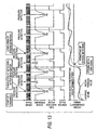
- Fig. 13 shows changes with time in the engine (crankshaft) speed, the fuel injection pulse, and the ignition pulse in the case where large explosion power is obtained in the initial explosion as a result of similar controls of the fuel injection and the ignition timing in a cranking process.
- the initial explosion is strong, the average value of the engine speed is rapidly increased, and, in a short time period, becomes equal to or larger than the stroke detection permitting predetermined speed, thereby permitting the stroke detection.
- the previous fuel injection is not immediately before the intake stroke, or specifically is in the expansion stroke. Therefore, the same fuel injection amount is again injected at the crank angle same as the previous one, so that an ideal fuel amount is sucked in the subsequent intake stroke, whereby engine start can be stabilized.
- fuel injection is performed at a predetermined crank angle in each rotation of the crankshaft, and, similarly in each rotation of the crankshaft, ignition is performed in the vicinity of the compression top dead center, whereby, although it may be weak, sure initial explosion can be obtained and the engine can be prevented from reversely rotating.
- ignition is performed at a timing which is advanced from the compression top dead center, there is the possibility that the engine reversely rotates.
- fuel injection and ignition are performed once in one cycle. This ignition is performed in the vicinity of a timing which is advanced by 10° from the compression top dead center, so that the engine speed can be rapidly increased.
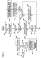
- step S48 of the computing process of Fig. 9 a minor program which is performed in step S48 of the computing process of Fig. 9 will be described with reference to the flowcharts of Figs. 14 to 16.
- an idling control flag F IDLE is reset to "0".
- step S51 a computing process of Fig. 21 which will be described later is conducted in step S51 to judge whether the engine is in the idling state or not. If the engine is in the idling state, the control proceeds to step S52. If not, the control proceeds to step S53.
- the centrifugal clutch is interposed between the engine and the transmission. As well known, when the engine speed is low, a centrifugal clutch is disengaged, and, when the engine speed is high, a centrifugal clutch is engaged. The engagement engine speed of the centrifugal clutch is previously set.
- the idling state is detected. According to the configuration, the idling state can be correctly detected without using a throttle opening sensor.
- step S53 the target ignition timing is calculated from a usual-running ignition timing map, and the control then proceeds to step S54.
- the highest torque is attained at a timing which is slightly advanced from the top dead center.
- the ignition timing is adjusted with being centered at the .highest-torque ignition timing.
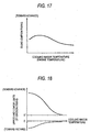
- step S54 in accordance with a control map of Fig. 17 which will be described later, the idling ignition timing is set on the basis of the cooling water temperature, and the control then returns to the main program.
- step 552 since the present state is the idling state, the target engine speed for allowing the engine to continue to rotate against friction is set on the basis of, for example, the cooling water temperature signal corresponding to the engine temperature. Thereafter, the control proceeds to step S55.
- the friction of the engine approximately depends on the viscosity of lubricating oil. As a low temperature at which lubricating oil has a high viscosity is further enhanced, the target engine speed is set to be higher, and, as the temperature is higher, the target engine speed is set to be lower.
- step S55 it is judged whether the idling control flag F IDLE is "0" or not. If the idling control flag F IDLE is "0", the control proceeds to step S56. If not, the control proceeds to step S57.
- step S56 it is judged whether the present engine speed is equal to or lower than the target engine speed calculated in step S52 or not. If the present engine speed is equal to or lower than the target engine speed, the control proceeds to step S58. If not, the control proceeds to step S59.
- step S58 the idling control flag F IDLE is set to "1", and the control then proceeds to step S60.
- step S60 a gain K which is used for changing and setting the ignition timing is set to an initial gain K INT which is relatively large, and the control then proceeds to step S61.
- step S61 the target ignition timing based on the cooling water temperature, i.e., the engine temperature is set from the idling ignition timing map shown in, for example, Fig. 17, and the control then proceeds to step S62 (Fig. 15).
- step S57 it is judged whether the idling control flag F IDLE is "1" or not. If the idling control flag F IDLE is "1", the control proceeds to step 563. If not, the control proceeds to step S64.
- step S63 it is judged whether the present engine speed is equal to or lower than a value which is obtained by subtracting a predetermined value ⁇ from the target engine speed or not.
- the idling control flag F IDLE is "1", and hence the present engine speed is ought to be lower than the target engine speed. In the above, therefore, it is judged whether or not the present engine speed that is lower than the target engine speed is within a range of the predetermined value ⁇ with respect to the target engine speed. If the present engine speed is equal to or lower than the value which is obtained by subtracting the predetermined value ⁇ from the target engine speed, the control proceeds to step S62. If not, the control proceeds to step S65.
- step S64 it is judged whether the idling control flag F IDLE is "2" or not. If the idling control flag F IDLE is "2", the control proceeds to step S66. If not, the control proceeds to step S62.
- step S66 it is judged whether the present engine speed is equal to or lower than a value which is obtained by adding the predetermined value ⁇ to the target engine speed or not.
- the idling control flag F IDLE is "2", and hence the present engine speed is ought to be higher than the target engine speed. In the above, therefore, it is judged whether or not the present engine speed that is higher than the target engine speed is within the range of the predetermined value ⁇ with respect to the target engine speed. If the present engine speed is equal to or lower than the value which is obtained by adding the predetermined value ⁇ to the target engine speed, the control proceeds to step S65. If not, the control proceeds to step S62.
- step S65 the idling control flag F IDLE is set to "3", and the control then proceeds to step S67.
- step S67 the gain K which is used for changing and setting the ignition timing is set to a usual gain K STD which is smaller than the initial gain K INT , and the control then proceeds to step S62.
- step S62 the integration value of the difference between the present engine speed and the target engine speed, i.e., the engine speed difference is calculated. Specifically, the present engine speed difference is added to the integration value of the engine speed difference which is stored in the storage apparatus.
- step S68 the control proceeds to step S68 to judge whether the idling control flag F IDLE is equal to or smaller than "2" or not. If the idling control flag F IDLE is equal to or smaller than "2", the control proceeds to step S69. If not, the control proceeds to step S70.
- step S69 it is judged whether or not the absolute value of the product of the gain K and the integration value of the engine speed difference is equal to or larger than 1 deg. corresponding to one degree of the ignition timing which is set to be advanced or retarded. If the absolute value of the product of the gain K and the integration value of the engine speed difference is equal to or larger than 1 deg., the control proceeds to step S71. If not, the control proceeds to step S72a.
- step S71 a value which is obtained by adding the integration value of the gain K and the integration value of the engine speed difference to the present target ignition timing is set as a new target ignition timing, and the control then proceeds to step 573.
- step S70 it is judged whether the idling control flag F IDLE is "3" or not. If the idling control flag F IDLE is "3", the control proceeds to step S74. If not, the control proceeds to step S75 (Fig. 16).
- step S74 it is judged whether or not the product of the gain K and the integration value of the engine speed difference is equal to or larger than +1 deg. corresponding to one degree of the ignition timing which is set to be advanced. If the product of the gain K and the integration value of the engine speed difference is equal to or larger than +1 deg., the control proceeds to step S76. If not, the control proceeds to step S77.
- step S77 it is judged whether or not the product of the gain K and the integration value of the engine speed difference is equal to or smaller than -1 deg. corresponding to one degree of the ignition timing which is set to be retarded. If the product of the gain K and the integration value of the engine speed difference is equal to or smaller than -1 deg., the control proceeds to step 578. If not, the control proceeds to step S72a.
- step S78 the idling control flag F IDLE is set to "5", and the control then proceeds to step 579.
- step S76 the idling control flag F IDLE is set to "4", and the control then proceeds to step S79.
- step S79 a value which is obtained by adding the integration value of the gain K and the integration value of the engine speed difference to the present target ignition timing is set as a new target ignition timing, and the control then proceeds to step S73.
- step S73 the integration value of the engine speed difference is reset or set to "0", and the control then proceeds to step S72a.
- step S72a in accordance with a control map of Fig. 18, upper and lower limits of the target ignition timing corresponding to the cooling water temperature, i.e., the engine temperature are set, and the control then proceeds to step S72b.
- the upper limit means a limiting value toward advance (a positive value with respect to the compression top dead center)
- the lower limit means a limiting value toward retard (a negative value with respect to the compression top dead center).
- the upper limit is set to be smaller, and the lower limit is set to be larger, or the width between the limits is made narrower.
- an ideal idling ignition timing is at 5° before the compression top dead center
- the upper limit of the target ignition timing is set to be closer to 5° before the compression top dead center
- the lower limit of the target ignition timing is set to be closer to the compression top dead center.
- step S72b the target ignition timing which is set in step S71 or S79 is restricted by the upper and lower limits of the target ignition timing which are set in step S72a, to set a new target ignition timing. Thereafter, the control proceeds to step S72c.
- step S72c the target ignition timing which is set in step S72b is output, and the control then returns to the main program.
- step S75 it is judged whether the idling control flag F IDLE is "4" or not. If the idling control flag F IDLE is "4", the control proceeds to step S80. If not, the control proceeds to step S81.
- step S80 it is judged whether or not the product of an advancing gain K ADV which is relatively small and the integration value of the engine speed difference is equal to or larger than +1 deg. corresponding to one degree of the ignition timing which is set to be advanced. If the product of the advancing gain K ADV and the integration value of the engine speed difference is equal to or larger than +1 deg., the control proceeds to step S82. If not, the control proceeds to step S83.
- step S83 it is judged whether or not the product of the usual gain K STD and the integration value of the engine speed difference is equal to or smaller than -1 deg. corresponding to one degree of the ignition timing which is set to be retarded. If the product of the usual gain K STD and the integration value of the engine speed difference is equal to or smaller than -1 deg., the control proceeds to step S84. If not, the control proceeds to step S85a.
- step S84 the idling control flag F IDLE is set to "5", and the control then proceeds to step S86.
- step S86 a value which is obtained by adding the integration value of the usual gain K STD and the integration valve of the engine speed difference to the present target ignition timing is set as a new target ignition timing, and the control then proceeds to step S87.
- step S82 a value which is obtained by adding the integration value of the advancing gain K ADV and the integration value of the engine speed difference to the present target ignition timing is set as a new target ignition timing, and the control then proceeds to step S87.
- step S81 it is judged whether or not the product of a retarding gain K DLY which is relatively small and the integration value of the engine speed difference is equal to or smaller than -1 deg. corresponding to one degree of the ignition timing which is set to be retarded. If the product of the retarding gain K DLY and the integration value of the engine speed difference is equal to or smaller than -1 deg., the control proceeds to step S88. If not, the control proceeds to step S89.
- step S89 it is judged whether or not the product of the usual gain K STD and the integration value of the engine speed difference is equal to or larger than +1 deg. corresponding to one degree of the ignition timing which is set to be advanced. If the product of the usual gain K STD and the integration value of the engine speed difference is equal to or larger than +1 deg., the control proceeds to step S90. If not, the control proceeds to step S85a.
- step S90 the idling control flag F IDLE is set to "4", and the control then proceeds to step S91.
- step S91 a value which is obtained by adding the integration value of the usual gain K STD and the integration value of the engine speed difference to the present target ignition timing is set as a new target ignition timing, and the control then proceeds to step S87.
- step S88 a value which is obtained by adding the integration value of the retarding gain K DLY and the integration value of the engine speed difference to the present target ignition timing is set as a new target ignition timing, and the control then proceeds to step S87.
- step S87 the integration value of the engine speed difference is reset or set to "0", and the control then proceeds to step S85a.
- step S85a in the same manner as step S72a, in accordance with the control map of Fig. 18, upper and lower limits of the target ignition timing corresponding to the cooling water temperature, i.e., the engine temperature are set, and the control then proceeds to step S85b.
- step S85b the target ignition timing which is set in step S82, S86, S88, or S91 is restricted by the upper and lower limits of the target ignition timing which is set in step S85a, to set a new target ignition timing. Thereafter, the control proceeds to step S85c.
- step S85c the target ignition timing is output, and the control then returns to the main program.
- the idling ignition timing map of Fig. 17 will be described.
- the cooling water temperature i.e., the engine temperature
- lubricating oil has a high viscosity.
- the engine therefore must continue to rotate against the friction due to the viscosity, and the ignition timing is set to be further advanced so as to attain the higher torque.
- the ignition timing is set to be less advanced, and hence sudden increase of the speed of an engine which is warmed up is prevented from occurring.
- kick-back in which the engine tries to reversely rotate and is then stopped occurs. Therefore, the ignition timing is set to a small value toward advance.
- the gain K is set to the initial gain K INT which is relatively large, and the target ignition timing corresponding to the cooling water temperature, i.e., the engine temperature at this time is set.
- the target ignition timing is changed to be advanced by a value which is obtained by multiplying the integration value of the speed difference between the target engine speed and the present engine speed with the gain K that is set to the initial gain K INT which is relatively large, whereby the engine speed is rapidly increased.
- the target ignition timing is changed to be retarded by a value which is obtained by similarly multiplying the integration value of the engine speed difference with the gain K that is set to the initial gain K INT which is relatively large, whereby the engine speed is rapidly reduced.
- the gain K is set to the usual gain K STD which is smaller than the initial gain K INT , and the ignition timing is changed to be advanced or retarded by the product of the gain K set to the usual gain K STD and the integration value of the engine speed difference.
- the integration value of the engine speed difference which is obtained by subtracting the present engine speed from the target engine speed is positive, the ignition timing is changed to be advanced, and the engine speed is increased.
- the integration value of the engine speed difference is negative, the ignition timing is changed to be retarded, and the engine speed is reduced.
- the changing amount of the target ignition timing in the changed side is set with using the advancing gain K ADV or the retarding gain K DLY which is relatively small. Namely, for example, in the case where the ignition timing is changed to be advanced in the previous setting, in the next and subsequent settings in which the ignition timing is changed to be advanced, the changing amount of the target ignition timing is set with using the advancing gain K ADV which is relatively small, and hence the ignition timing is hardly changed in the substantially same side.
- the changing amount of the target ignition timing is set with using the usual gain K STD , and hence the ignition timing is easily changed in the opposite side. This is similarly performed also in the case where the ignition timing is previously changed to be retarded.
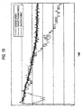
- Fig. 19 shows changes with time in the ignition timing, the target engine speed, and the engine speed immediately after start of the engine which is controlled by the computing processes of Figs. 14 to 16.
- the ignition timing is rapidly changed to be advanced by the initial gain K INT , whereby the engine speed is rapidly increased.
- the gain is switched to the usual gain K STD , so that overshoot of the engine speed with respect to the target engine speed is suppressed.
- the ignition timing is gradually changed to be retarded, or more strictly to a small value toward advance.
- the ignition timing is not changed even when the target engine speed and the engine speed do not coincide with each other. This is caused by the above-mentioned effect of suppressing the change of the ignition timing in the same side. Namely, in the portion A, continuous changes of the ignition timing toward retard are suppressed by the retarding gain K DLY which is relatively small, whereby the control can be prevented from hunting.
- the engine speed is caused to follow the target engine speed while ensuring the responsiveness, by the usual gain K STD .
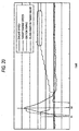
- Fig. 20 shows changes with time in the ignition timing, the target engine speed, the engine speed, and the idling ignition timing set value which is set in accordance with the cooling water temperature, i.e., the engine temperature in the case where, when the engine is warmed up and the idling is stabilized, the throttle is largely opened at time t 01 and the throttle is totally closed or the state is returned to the idling state at time t 02 .
- the ignition timing is once changed to the retarding side, and then largely changed toward advance, to obtain a sharp increase in torque, whereby the engine speed is rapidly increased.
- the idling ignition timing set value is set to a value which is smaller than that which is set before the throttle-on operation.
- the ignition timing coincides with the idling ignition timing set value, and is thereafter gradually changed toward advance.
- the ignition timing which is optimum for making the idling engine speed coincident with the target engine speed is ought to be an ignition timing in the portion C in the figure.
- the idling ignition timing set value according to the cooling water temperature is set to be smaller, in order to rapidly reduce the engine speed in response to a throttle-off operation.
- the ignition timing at throttle-off is set to a value in the vicinity of the portion C, the torque is excessively generated and the engine speed is hardly reduced. In this way, the idling ignition timing set value according to the cooling water temperature is set to be small, so that the engine speed at throttle-off can be rapidly reduced.
- step S101 it is judged in step S101 whether the engine speed calculated by the engine speed calculating section 26 is equal to or lower than the engagement speed of the centrifugal clutch or not. If the engine speed is equal to or lower than the centrifugal clutch engagement speed, the control proceeds to step S102. If not, the control proceeds to step S103.
- step S102 the atmospheric pressure is detected from the atmospheric pressure signal, and the control then proceeds to step S104.
- the intake pressure immediately before the intake valve is opened such as shown in Fig. 4 is substantially equal to the atmospheric pressure. Therefore, the atmospheric pressure is detected with using the intake pressure immediately before the intake valve is opened. According to the configuration, an atmospheric pressure sensor is not required, and the number of parts is correspondingly reduced, so that the cost can be lowered.
- step S104 for example, the intake pressure at crank pulse "18" shown in Fig. 4 is read as the intake pressure at the predetermined crank angle, and the control then proceeds to step S105.
- step S105 on the basis of the atmospheric pressure detected in step S102, an intake pressure idling predetermined value corresponding to the atmospheric pressure is set in accordance with a control map of Fig. 22a, and the control then proceeds to step S106.
- the control map of Fig. 22a is configured so that, as the atmospheric pressure is higher, the intake pressure idling predetermined value is set to a larger value.
- the intake pressure idling predetermined value may not be set so as to be continuously changed as shown in Fig. 22a.
- the value may be set in a somewhat stepwise manner.
- the intake pressure idling predetermined value is set to a larger value.
- step S106 it is judged whether or not the intake pressure at the predetermined crank angle which is read in step S104 is equal to or lower than the intake pressure idling predetermined value which is set in step S105. If the intake pressure is equal to or lower than the intake pressure idling predetermined value, the control proceeds to step S107. If not, the control proceeds to step S103.
- step S107 it is judged that the engine is in the idling state, and the control then proceeds to step S52 of the computing process of Fig. 14.
- step S103 it is judged that the engine is not in the idling state, and the control then proceeds to step S52 of the computing process of Fig. 14.
- the intake pressure idling predetermined value is set in accordance with the atmospheric pressure. As described above, the intake pressure is varied in accordance with the atmospheric pressure. When the intake pressure idling predetermined value is not set in accordance with the atmospheric pressure, therefore, the idling state cannot be correctly detected.
- the intake pressure idling predetermined value When the intake pressure idling predetermined value is not set in accordance with the atmospheric pressure and is set to be slightly larger while producing a margin, for example, the intake pressure does not exceed the idling predetermined value although the engine speed is increased, and hence the transfer to an adequate acceleration control is delayed. Conversely, when the intake pressure idling predetermined value is set to be slightly smaller, detection of the idling state is excessively severe so that the control in the idling state and that in the non-idling state hunt. When the intake pressure idling predetermined value is set in accordance with the atmospheric pressure, therefore, the idling state can be correctly detected, and transfer to the control in the non-idling state can be adequately performed.
- Fig. 23 shows changes with time in the ignition timing IGT, the engine speed N, and the intake pressure P in the case where the throttle opening TH is increased very slowly from time t 01 with starting from the totally closed state of the throttle under the condition that, after the engine is sufficiently warmed up, the upper and. lower limits IGT H , IGT L of the ignition timing are adequately set in accordance with the cooling water temperature, i.e., the engine temperature, and the intake pressure idling predetermined value P 0 is adequately set in accordance with the atmospheric pressure.
- the lower limit IGT L of the ignition timing is set to a negative value having a relatively small absolute value, and the ignition timing IGT is restricted at time t 02 by the lower limit IGT L of the ignition timing.
- the intake pressure P is raised, and the engine speed N is correspondingly increased.
- the engine speed N becomes equal to higher than the centrifugal clutch engagement speed N 0 or at time t 03 . Consequently, transfer to the acceleration control is performed, and the ignition timing IGT is changed toward advance, so that the engine speed N is largely increased.
- Fig. 24 shows a simulation in which the upper and lower limits IGT H , IGT L of the ignition timing are not set in accordance with the cooling water temperature, i.e., the engine temperature, and the intake pressure idling predetermined value P 0 is not set in accordance with the atmospheric pressure.
- the upper limit IGT H of the ignition timing is set to a largish value
- the lower limit IGT L of the ignition timing is set to a smallish value
- the intake pressure idling predetermined value P 0 is set to a largish value
- the throttle opening TH is increased very slowly from time t 11 .
- the ignition timing IGT is changed more and more to the retarding side, and reaches the lower limit IGT L of the ignition timing to be restricted thereto, at time t 12 at which a considerably long time period has elapsed from the start of the process of opening the throttle, with the result that the intake pressure P is raised and the engine speed N is increased.
- the intake pressure idling predetermined value Po is large, the engine speed N becomes equal to higher than the centrifugal clutch engagement speed No at time t 13 at which the intake pressure P has not yet reached the idling predetermined value P 0 .
- the transfer to the acceleration control is permitted only after a considerably long time period has elapsed from time t 11 or the start of the process of opening the throttle.
- a situation similar to the above occurs also in the case where, for example, the closing degree of the throttle valve is adjusted by an idle screw. Even when the idle screw is adjusted, the idling engine speed is hardly increased.
- the engine controller of the invention can be similarly applied also to an engine of the cylinder injection type, or a so-called direction-injection engine.
- the engine controller of the invention can be similarly applied also to an engine having two or more cylinders, or a so-called multicylinder engine.
- the engine control unit can be realized by various kinds of computing circuits in place of a microcomputer.
- the ignition timing is set in accordance with the difference between the target engine speed and the detected engine speed.
- the ignition timing can be changed toward advance to increase the engine speed, or changed to the retarding side to reduce the engine speed.
- an unstable engine speed in an idling state such as a state immediately after start of rotation of an engine can be controlled to a rotation state which is adequate at this time.
- the engine controller of claim 2 of the invention when the ignition timing is changed to one of an advancing side and a retarding side, continuation of a change of the ignition timing to the same side is avoided. Therefore, the engine speed in the idling state can be prevented from being excessively increased, or from being excessively reduced.
- the ignition timing is set by multiplying an integration value of the difference between the target engine speed and the detected engine speed, with a predetermined gain.
- the ignition timing is changed, whereby the engine speed in the idling state can be prevented from being excessively increased, or from being excessively reduced.
- the gain which is to be multiplied with the integration value of the engine speed difference is adequately set, the engine speed in the idling state immediately after start of rotation of the engine can be rapidly increased, and the engine speed in the idling state can be surely prevented from being excessively increased, or from being excessively reduced.
- the ignition timing change setting gain for the same side is set to a smaller value, the ignition timing change setting gain being to be multiplied with the integration value of the difference between the target engine speed and the detected engine speed. Therefore, the engine speed in the idling state can be surely prevented from being excessively increased, or from being excessively reduced.
- the gain which is to be multiplied with the integration value of the difference between the target engine speed and the detected engine speed is set to a larger value. Therefore, the engine speed after start of rotation of the engine can be rapidly increased.
- the ignition timing at a state change of the engine from a state other than the idling state to the idling state is set on the basis of the detected engine temperature. Therefore, the engine speed can be adequately reduced in an idling state transition period from a throttle-on state to a throttle-off state.
- upper and lower limits of the ignition timing are set on the basis of the engine temperature, and the ignition timing is restricted by the upper and lower limits. Therefore, the sense of incongruity that the engine speed is not changed in spite of a change of the throttle opening can be reduced.
- the upper and lower limits of the ignition timing are set so that the width between the upper and lower limits is narrower as the engine temperature is higher. Therefore, at a time when the engine temperature is high and the warming-up operation is ended, the responsiveness of the engine speed change with respect to a change of the throttle opening can be improved.
- a predetermined value of the intake pressure for detecting the idling state is set on the basis of a detected atmospheric pressure, and, when the intake pressure is equal to or lower than the predetermined value for detecting the idling state when the phase of the crankshaft has a predetermined value, the idling state of the engine is detected. Therefore, the idling state of the engine can be surely detected, and the control can be surely performed in the engine operation state other than the idling state.
- the predetermined value of the intake pressure for detecting the idling state is set to be larger. Therefore, the idling state of the engine can be surely detected in accordance with a change of the atmospheric pressure, and the control when the atmospheric pressure is changed can be surely performed in the engine operation state other than the idling state.
- the atmospheric pressure is detected on the basis of the detected intake pressure. Therefore, an atmospheric pressure sensor is not required, and the. number of parts is correspondingly reduced, so that the cost can be lowered.
- the engine controller of claim 12 of the invention when the detected engine speed detected is equal to or lower than an engagement speed of the centrifugal clutch, the idling state of the engine is detected. Therefore, the idling state of the engine can be surely detected.
Landscapes
- Engineering & Computer Science (AREA)
- Chemical & Material Sciences (AREA)
- Combustion & Propulsion (AREA)
- Mechanical Engineering (AREA)
- General Engineering & Computer Science (AREA)
- Theoretical Computer Science (AREA)
- Signal Processing (AREA)
- Electrical Control Of Ignition Timing (AREA)
- Combined Controls Of Internal Combustion Engines (AREA)
- Electrical Control Of Air Or Fuel Supplied To Internal-Combustion Engine (AREA)
Abstract
An unstable idling state immediately after engine start is stabilized. <??>The difference between a target idling engine speed corresponding to the cooling water temperature and an actual engine speed is integrated. The ignition timing is changed toward advance or retard while using a value which is obtained by multiplying the integration value of the engine speed difference with a gain, as an ignition timing changing amount. Immediately after engine start, the gain is set to a relatively large initial gain so as to rapidly increase the engine speed. When the engine speed approaches the target engine speed, the gain is set to a smaller usual gain, and, in a change to the same advancing or retarding side, a change to an ignition timing in the same side is suppressed with using a smaller advancing or retarding gain. In a throttle-off state, an ignition timing corresponding to the cooling water temperature is set so as to rapidly reduce the engine speed. <IMAGE>
Description
The present invention relates to an engine controller
which controls an engine, and more particularly to an
apparatus suitable for controlling an engine having a fuel
injection apparatus which injects fuel.
Recently, as a fuel injection apparatus which is
called an injector is more widely used, the fuel injection
timing, the amount of injected fuel, i.e., the air-fuel
ratio, and the like can be more easily controlled, so that
a higher output power, smaller fuel consumption, exhaust
gas purification, and the like can be enhanced. With
respect to the fuel injection timing, particularly, the
state of an intake valve in a strict sense, or the phase
state of a camshaft in a usual sense is detected, and fuel
is usually injected in accordance with the detected state.
However, a so-called cam sensor for detecting the phase
state of a camshaft is expensive. In a two-wheeled
vehicle, particularly, a cam sensor cannot be often
employed because of a problem in that the size of a
cylinder head is increased. For example, JP-A-10-227252
proposes an engine controller in which the phase state of
a crankshaft and the intake pressure are detected and the
stroke state of a cylinder is detected from them. When
this conventional technique is used, the stroke state can
be detected without detecting the phase of a camshaft, and
hence the fuel injection timing and the like can be
controlled in accordance with the stroke state.
When an engine is electronic-controlled as described
above, it is possible to control also the ignition timing.
The ignition timing affects the torque of an engine.
When the ignition timing is set to be slightly advanced
from the compression top dead center, the highest torque
is generated. When the ignition timing is changed from it
toward advance or retard, the torque is reduced. Actually,
however, a specific ignition timing controlling technique
for, in, for example, a state immediately after start of
rotation of an engine, adequately controlling the unstable
engine speed in an idling state is not proposed.
The invention is developed in order to solve the
problems discussed above, and has an objective of
providing an engine controller which can adequately
control the engine speed in an idling state immediately
after engine start or the like.
In order to solve the problems, the engine controller
of claim 1 of the invention is characterized in that the
apparatus comprises: crankshaft phase detecting means for
detecting a phase of a crankshaft; intake pressure
detecting means for detecting an intake pressure of an
intake passage of an engine; stroke detecting means for
detecting a stroke of the engine on the basis of the phase
of the crankshaft detected by the crankshaft phase
detecting means, and the intake pressure detected by the
intake pressure detecting means; and engine controlling
means for controlling an operation state of the engine on
the basis of the stroke of the engine detected by the
stroke detecting means, and the engine controlling means
comprises: engine speed detecting means for detecting a
speed of the engine; idling detecting means for detecting
an idling.state of the engine; target engine speed setting
means for, when the idling state of the engine is detected
by the idling detecting means, setting a target engine
speed; and idling ignition timing setting means for, when
the idling state of the engine is detected by the idling
detecting means, setting an ignition timing in accordance
with a difference between the target engine speed set by
the target engine speed setting means and the engine speed
detected by the engine speed detecting means.
The engine controller of claim 2 of the invention is
characterized in that, in the invention of claim 1, when
the ignition timing is changed to one of an advancing side
and a retarding side, the idling ignition timing setting
means avoids continuation of a change of the ignition
timing to a same side.
The engine controller of claim 3 of the invention is
characterized in that, in the invention of claim 1 or 2,
the idling ignition timing setting means sets the ignition
timing by multiplying an integration value of the
difference between the target engine speed set by the
target engine speed setting means and the engine speed
detected by the engine speed detecting means, with a
predetermined gain.
The engine controller of claim 4 of the invention is
characterized in that, in the invention of claim 3, when
the ignition timing is changed to one of the advancing
side and the retarding side, the idling ignition timing
setting means sets the ignition timing change setting gain
for the same side to a smaller value, the ignition timing
change setting gain being to be multiplied with the
integration value of the difference between the target
engine speed set by the target engine speed setting means
and the engine speed detected by the engine speed
detecting means.
The engine controller of claim 5 of the invention is
characterized in that, in the invention of claim 3 or 4,
immediately after start of rotation of the engine, the
idling ignition timing setting means sets the gain to a
larger value, the gain being to be multiplied with the
integration value of the difference between the target
engine speed set by the target engine speed setting means
and the engine speed detected by the engine speed
detecting means.
The engine controller of claim 6 of the invention is
characterized in that, in the invention of any one of
claims 1 to 5, the apparatus further comprises engine
temperature detecting means for detecting a temperature of
the engine, and the idling ignition timing setting means
sets the ignition timing at a state change of the engine
from a state other than the idling state to the idling
state, on the basis of the engine temperature detected by
the engine temperature detecting means.
The engine controller of claim 7 of the invention is
characterized in that, in the invention of any one of
claims 1 to 6, the apparatus further comprises engine
temperature detecting means for detecting a temperature of
the engine, and the idling ignition timing setting means
sets upper and lower limits of the ignition timing on the
basis of the engine temperature detected by the engine
temperature detecting means, and restricts the ignition
timing by the upper and lower limits.
The engine controller of claim 8 of the invention is
characterized in that, in the invention of claim 7, the
idling ignition timing setting means sets the upper and
lower limits of the ignition timing so that a width
between the upper and lower limits is narrower as the
engine temperature detected by the engine temperature
detecting means is higher.
The engine controller of claim 9 of the invention is
characterized in that, in the invention of any one of
claims 1 to 8, the apparatus further comprises atmospheric
pressure detecting means for detecting an atmospheric
pressure, and the idling detecting means sets a
predetermined value of the intake pressure for detecting
the idling state, on the basis of the atmospheric pressure
detected by the atmospheric pressure detecting means, and,
when the intake pressure detected by the intake pressure
detecting means is equal to or lower than the
predetermined value for detecting the idling state when
the phase of the crankshaft detected by the crankshaft
phase detecting means has a predetermined value, detects
the idling state of the engine.
The engine controller of claim 10 of the invention is
characterized in that, in the invention of claim 9, the
idling detecting means sets the predetermined value of the
intake pressure for detecting the idling state to be
larger as the atmospheric pressure detected by the
atmospheric pressure detecting means is higher.
The engine controller of claim 11 of the invention is
characterized in that, in the invention of claim 9 or 10,
the atmospheric pressure detecting means detects the
atmospheric pressure on the basis of the intake pressure
detected by the intake pressure detecting means.
The engine controller of claim 12 of the invention is
characterized in that, in the invention of any one of
claims 1 to 11, the apparatus further comprises a
centrifugal clutch between the engine and a transmission,
and, when the engine speed detected by the engine speed
detecting means is equal to or lower than an engagement
speed of the centrifugal clutch, the idling detecting
means detects the idling state of the engine.
Hereinafter, embodiments of the invention will be
described.
Fig. 1 is a diagram showing the configuration of, for
example, an engine for a motorcycle and an example of a
control apparatus for the engine. The engine 1 is a
single-cylinder four-cycle engine of a relatively small
displacement, and comprises a cylinder body 2, a
crankshaft 3, a piston 4, a combustion chamber 5, an
intake pipe (intake passage) 6, an intake valve 7, an
exhaust pipe 8, an exhaust valve 9, a spark plug 10, and
an ignition coil 11. A throttle valve 12 which is opened
or closed in accordance with the degree of an accelerator
operation is disposed in the intake pipe 6, and an
injector 13 serving as a fuel injection apparatus is
disposed in the intake pipe 6 downstream from the throttle
valve 12. The injector 13 is connected to a filter 18
which is disposed in a fuel tank 19, a fuel pump 17, and a
pressure control valve 16. A centrifugal clutch is
interposed between the engine 1 and a transmission.
The operation state of the engine 1 is controlled by
an engine control unit 15. As control inputs of the
engine control unit 15, i.e., means for detecting the
operation state of the engine 1, the following sensors are
disposed: a crank angle sensor 20 which detects the
rotation angle or the phase of the crankshaft 3; a cooling
water temperature sensor 21 which detects the temperature
of the cylinder body 2 or the cooling water temperature,
i.e., the temperature of the engine body; an exhaust air-fuel
ratio sensor 22 which detects the air-fuel ratio in
the exhaust pipe 8; an intake pressure sensor 24 which
detects the intake pressure in the intake pipe 6; and an
intake temperature sensor 25 which detects the temperature
in the intake pipe 6, i.e., the intake temperature. The
engine control unit 15 receives detection signals of these
sensors, and outputs a control signal to the fuel pump 17,
the pressure control valve 16, the injector 13, and the
ignition coil 11.
The principle of a crank angle signal which is output
from the crank angle sensor 20 will be described. In the
embodiment, as shown in Fig. 2a, a plurality of teeth 23
are protruded at substantially equal intervals from the
outer circumference of the crankshaft 3, and the crank
angle sensor 20 such as a magnetic sensor detects the
approach of each tooth, applies an appropriate electric
process, and then transmits pulse signals. The pitch of
the teeth 23 in the circumferential direction is set to
30° in terms of the phase (rotation angle) of the
crankshaft 3, and the width of each of the teeth 23 in the
circumferential direction is set to 10° in terms of the
phase (rotation angle) of the crankshaft 3. In one place
only, however; the pitch is not set as described above,
but set twice the pitch of the other teeth 23. In the
place, as indicated by the two-dot chain line in Fig. 2a,
no tooth is formed in a portion where a tooth should
originally exist, or special setting is applied. This
portion corresponds to an unequal interval. Hereinafter,
this portion is often referred to as toothless portion.
When the crankshaft 3 is rotated at a constant speed,
therefore, the pulse signal train of the teeth 23 appears
as shown in Fig. 2b. Fig. 2a shows the state at the
compression top dead center (also the state at the exhaust
top dead center is identical in form). As shown in the
figure, the pulse signals are numbered in the sequence
that the pulse signal immediately before the compression
top dead center is indicated by "0", the next pulse by "1",
and the next next pulse by "2", and the last number is set
to "4". The portion subsequent to the tooth 23
corresponding to the pulse signal of "4" is the toothless
portion. Therefore, it is assumed that a tooth exists in
the portion, and an extra count for one tooth is performed
so that the pulse signal for the next tooth 23 is numbered
"6". When this numbering process is repeated, the
toothless portion approaches the portion subsequent to the
pulse signal of "16", and therefore an extra count for one
tooth is performed in the same manner as described above
so that the pulse signal for the next tooth 23 is numbered
"18". When the crankshaft 3 makes two rotations, all the
cycles of the four strokes are completed. When the
numbering process has proceeded to "23", therefore, the
pulse signal for the subsequent tooth 23 is again numbered
"0". In principle, the portion immediately after the
pulse signal of the "0"-numbered tooth 23 ought to
correspond to the compression top dead center. In this
way, the detected pulse signal train, or each single pulse
signal is defined as a crank pulse. When stroke detection
is performed on the basis of the crank pulse as described
later, a crank timing can be detected. Alternatively, the
teeth 23 may be disposed on the outer periphery of a
member which is rotated in synchronization with. the
crankshaft 3. The alternative is strictly identical with
the configuration described above.
By contrast, the engine control unit 15 is configured
by a microcomputer which is not shown, etc. Fig. 3 is a
block diagram showing an embodiment of an engine control
computing process which is performed by the microcomputer
in the engine control unit 15. The computing process
comprises: an engine speed calculating section 26 which
calculates the engine speed from the crank angle signal; a
crank timing detecting section 27 which detects crank
timing information, i.e., the stroke state from the crank
angle signal and the intake pressure signal; a stroke
detection permitting section 29 which reads the engine
speed calculated by the engine speed calculating section
26, which outputs stroke detection permission information
to the crank timing detecting section 27, and which
fetches and outputs stroke detection information produced
by the crank timing detecting section 27; a cylinder air
mass calculating section 28 which reads the crank timing:
information detected by the crank timing detecting section
27, and which calculates a cylinder air mass (intake air
mass) from the intake temperature signal, the cooling
water temperature (engine temperature) signal, the intake
pressure signal, and the engine speed calculated by the
engine speed calculating section 26; a target air-fuel
ratio calculating section 33 which calculates a target
air-fuel ratio from the engine speed calculated by the
engine speed calculating section 26, and the intake
pressure signal; a fuel injection amount calculating
section 34 which calculates a fuel injection amount and a
fuel injection timing from the target air-fuel ratio
calculated by the target air-fuel ratio calculating
section 33, the intake pressure signal, the cylinder air
mass calculated by the cylinder air mass calculating
section 28, the stroke detection information output from
the stroke detection permitting section 29, and the
cooling water temperature signal; an injection pulse
.outputting section 30 which reads the crank timing
information detected by the crank timing detecting section
27, and which outputs toward the injector 13 an injection
pulse corresponding to the fuel injection amount and the
fuel injection timing calculated by the fuel injection
amount calculating section 34; an ignition timing
calculating section 31 which calculates an ignition timing
from the engine speed calculated 'by the engine speed
calculating section 26, the target air-fuel ratio set by
the target air-fuel ratio calculating section 33, and the
stroke detection information output from the stroke
detection permitting section 29; and an ignition pulse
outputting section 32 which reads the crank timing
information detected by the crank timing detecting section
27, and which outputs toward the ignition coil 11 an
ignition pulse corresponding to the ignition timing set by
the ignition timing calculating section 31.
From a time change rate of the crank angle signal,
the engine speed calculating section 26 calculates the
rotation speed of the crankshaft serving as an output
shaft of the engine, as the engine speed. Specifically,
an instantaneous value of the engine speed which is
obtained by dividing the phase between the adjacent teeth
23 by a time required for detecting the corresponding
crank pulse, and an average value of the engine speed
consisting of the moving average value are calculated.
The crank timing detecting section 27 is configured:
in a similar manner as the stroke judging apparatus
disclosed in JP-A-10-227252 described above. As shown in
Fig. 4, for example, the stroke state of each cylinder is
detected, and the detected state is output as the crank
timing information. In a four-cycle engine, namely, a
crankshaft and a camshaft continue to be rotated at a
predetermined phase difference. When the crank pulse is
read as shown in Fig. 4, for example, crank pulse "9" 'or
"21" which is a fourth pulse counted from the above-mentioned
toothless portion is in either of the exhaust
stroke or the compression stroke. In the exhaust stroke,
as well known, the exhaust valve is opened, the intake
valve is closed, and hence the intake pressure is high.
In an early stage of the compression stroke, the intake
valve remains to be opened and hence the intake pressure
is low, or, even when the intake valve is closed, the
intake pressure is lowered in the preceding intake stroke.
Therefore, crank pulse "21" which is at a timing of a low
intake pressure indicates that the cylinder is in the
compression stroke, and a timing immediately after crank
pulse "0" is obtained corresponds to the compression top
dead center. When one of the stroke states is detected in
this way, the stroke is interpolated with the rotation
speed of the crankshaft, so that the present stroke state
can be detected more finely.
The stroke detection permitting section 29 outputs
stroke detection permission information for the crank
timing detecting section 27 in accordance with a computing
process shown in Fig. 5. As described above, detection of
a stroke from the crank pulse requires at least two
rotations of the crankshaft. During this period, the
crank pulse including the toothless portion must be
stabilized. In a single-cylinder engine of a relatively
small displacement as in the embodiment, however, the
rotation state of the engine is not stabilized in a
starting process or so-called cranking. Therefore, the
rotation state of the engine is judged by the computing
process of Fig. 5, and stroke detection is permitted.
The computing process of Fig. 5 is executed with
using, for example, an input of the crank pulse as a
trigger. Although a step for communication is not
particularly disposed in the flowchart, information which
is obtained as a result of the computing process is
updated and stored at any time into a storage apparatus,
and information and programs which are necessary for the
computing process are read out at any time from the
storage apparatus.
In the computing process, the average value of the
engine speed calculated by the engine speed calculating
section 26 is first read in step S11.
Then, the control proceeds to step S12 to judge
whether or not the average value of the engine speed which
is read in step S11 is equal to or larger than a preset
stroke detection permitting predetermined speed that is
equal to or larger than a rotation speed corresponding to
the initial explosion. If the average value of the engine
speed is equal to or larger than the stroke detection
permitting predetermined speed, the control proceeds to
step S13. If not, the control proceeds to step S14.
In step S13, information indicative of permitting of
stroke detection is output, and the control then returns
to a main program.
In step S14, information indicative of disabling of
stroke detection is output, and the control then returns
to the main program.
According to the computing process, stroke detection
is permitted after the average value of the engine speed
becomes equal to or larger than the stroke detection
permitting predetermined rotation speed that is equal to
or larger than at least the speed corresponding to the
initial explosion. Therefore, the crank pulse is
stabilized, and correct stroke detection can be performed.
As shown in Fig. 6, the cylinder air mass calculating
section 28 has a three-dimensional map for calculating the
cylinder air mass from the intake pressure signal and the
engine speed calculated by the engine speed calculating
section 26. For example, the three-dimensional map of the
cylinder air mass requires only measurement of the
cylinder air mass when the intake pressure is changed
while rotating the engine at a predetermined speed, and
such measurement can be conducted by a relatively simple
experiment. Therefore, the map can be easily produced.
When there is a sophisticated engine simulator, the map
may be produced with using the simulator. Since the
cylinder air mass is changed depending on the temperature
of the engine, the mass may be corrected with using the
cooling water temperature (engine temperature) signal.
As shown in Fig. 7, the target air-fuel ratio
calculating section 33 has a three-dimensional map for
calculating the target air-fuel ratio from the intake
pressure signal and the engine speed calculated by the
engine speed calculating section 26. The three-dimensional
map can be theoretically set to some extent.
The air-fuel ratio usually correlates with the torque. As
the air-fuel ratio is smaller or the fuel is larger and
the air is smaller, the torque is larger, and the
efficiency is lower. By contrast, as the air-fuel ratio
is larger or the fuel is smaller and the air is larger,
the torque is smaller, and the efficiency is higher. A
state of a small air-fuel ratio is called rich, and that
of a large air-fuel ratio is called lean. The leanest
state is at an air-fuel ratio which is called a so-called
ideal air-fuel ratio or a stoichiometric ratio, and at
which gasoline completely burns, i.e., an air-fuel ratio
of 14.7.
The engine speed is one of indices indicating the
operation state of the engine. Usually, in the high
engine speed side, the air-fuel ratio is set to be large,
and, in the low engine speed side, the ratio is set to be
small. This is conducted in order to enhance the
responsiveness of the torque in the low engine speed side,
and to enhance the responsiveness of the rotation state in
the high engine speed side. The intake pressure is one of
indices indicating the engine load state such as the
throttle opening. Usually, in a state where the engine
load is large, or the throttle opening is large and the
intake pressure is high, the air-fuel ratio is set to be
small, and, in a state where the engine load is small, or
the throttle opening is small and the intake pressure is
low, the air-fuel ratio is set to be large. This is
conducted in order to place emphasis on the torque in a
state where the engine load is large, and to place
emphasis on the efficiency in a state where the engine
load is small.
As described above, the target air-fuel ratio is a
numerical value from which physical meanings can be easily
grasped. In accordance with the required output
characteristics of the engine, therefore, the target air-fuel
ratio can be set to some extent. It is a matter of
course that tuning can be conducted in accordance with the
output characteristics of an actual vehicle.
The target air-fuel ratio calculating section 33 has
a transient correcting section 29 which detects transient
of the operation state of the engine, specifically, the
acceleration state or the deceleration state, from the
intake pressure signal, and which corrects the target air-fuel
ratio in accordance with the detected transient. As
shown in Fig. 8, for example, the intake pressure can be
deemed as a resulting phenomenon of a throttle operation.
Therefore, it will be see that, when the intake pressure
is raised, the throttle is opened and acceleration is
requested, or the acceleration state is set. When the
acceleration state is detected, for example, the target
air-fuel ratio is temporarily set to the rich side in
accordance with the detected state, and then returned to
the original target air-fuel ratio. The return to the
target air-fuel ratio may be realized by a known method
such as that in which the weighting coefficient of a
weighted average value of the air-fuel ratio which is set
to the rich side in transient, and the original target
air-fuel ratio is gradually changed. By contrast, when
the deceleration state is detected, the target air-fuel
ratio may be set to be leaner than the original target
air-fuel ratio so as to place emphasis on the efficiency.
The fuel injection amount calculating section 34
calculates the fuel injection amount and the fuel
injection timing in engine start and usual operation, in
accordance with a computing process shown in Fig. 9. The
computing process of Fig. 9 is executed with using, for
example, an input of the crank pulse as a trigger.
Although a step for communication is not particularly
disposed in the flowchart, information which is obtained
as a result of the computing process is updated and stored
at any time into the storage apparatus, and information
and programs which are necessary for the computing process
are read out at any time from the storage apparatus.
In the computing process, the stroke detection
information output from the stroke detection permitting
section 29 is first read in step S21.
Then, the control proceeds to step S22 to judge
whether the stroke detection by the crank timing detecting
section 27 is uncompleted or not. If the stroke detection
is uncompleted, the control proceeds to step S23. If not,
the control proceeds to step S24.
In step S23, it is judged whether a fuel injection
number counter n is "0" or not. If the fuel injection
number counter n is "0", the control proceeds to step S25.
If not, the control proceeds to step S26.
In step S25, it is judged whether the next fuel
injection is third or subsequent fuel injection counted
from the beginning of engine start or not. If the next
fuel injection is third or subsequent fuel injection, the
control proceeds to step S27. If not, the control
proceeds to step S28.
In step S27, the intake pressure at a preset
predetermined crank angle during two rotations of the
crankshaft, in the embodiment, at crank pulse "6" or "8"
in Figs. 2 and 4 is read from, for example, an intake
pressure storage section which is not shown, and the
difference between the intake pressures is calculated.
Then, the control proceeds to step S29.
In step S29, it is judged whether or not the intake
pressure difference calculated in step S28 is equal to or
larger than a predetermined value by which the stroke can
be identified to some extent. If the intake pressure
difference is equal to or larger than the predetermined
value, the control proceeds to step S30. If not, the
control proceeds to step S28.
In step S30, the total fuel injection amount is
calculated on the basis of the smaller one of the intake
pressures at the predetermined crank angle during two
rotations of the crankshaft which are read in step S27.
Then, the control proceeds to step S31.
By contrast, in step S28, the cooling water
temperature, i.e., the engine temperature is read, and the
total fuel injection amount corresponding to the cooling
water temperature is calculated, so that, for example, the
total fuel injection amount is made larger as :the cooling
water temperature is lower. Thereafter, the control
proceeds to step S31. The total fuel injection amount
which is calculated in step S28 or step S30 means a fuel
injection amount that is originally requested to be
injected once in each cycle, or two rotations of the
crankshaft, and before the intake stroke. When the stroke
is already detected and the fuel injection amount
corresponding to the cooling water temperature is injected
once before the intake stroke, therefore, the engine
adequately rotates in accordance with the cooling water
temperature, i.e., the engine temperature.
In step S31, a half of the total fuel injection
amount which is set in step S30 is set as a present fuel
injection amount, and a predetermined crank angle in each
rotation, i.e., one rotation of the crankshaft, or, in the
embodiment, the timing of the falling edge of crank pulse
"10" or "22" in Figs. 2 and 4 is set as the fuel injection
timing. Then, the control proceeds to step S32.
In step S32, the fuel injection number counter is set
to "1" and the control then returns to the main program.
On the other hand, in step S24, it is judged whether
the previous fuel injection is immediately before the
intake stroke or not. If the previous fuel injection is
immediately before the intake stroke, the control proceeds
to step S33. If not, the control proceeds to step S26.
In step S26, the previous fuel injection amount is
set as the present fuel injection amount, and, in the same
manner as step S31, a predetermined crank angle in each
rotation, i.e., one rotation of the crankshaft is set as
the fuel injection timing. The control then proceeds to
step S34.
In step S34, the fuel injection number counter is set
to "0" and the control then returns to the main program.
In step S33, the fuel injection amount and the fuel
injection timing in usual operation corresponding to the
target air-fuel ratio, the cylinder air mass, and the
intake pressure are set, and the control 'then proceeds to
step S35. Specifically, for example, the cylinder air
mass calculated by the cylinder air mass calculating
section 28 is divided by the target air-fuel ratio
calculated by the target air-fuel ratio calculating
section 33, whereby the necessary cylinder fuel mass can
be obtained. When the obtained mass is multiplied with,
for example, the flow characteristic of the injector 13,
it is possible to obtain a fuel injection time. From the
time, the fuel injection amount and the fuel injection
timing can be calculated.
In step S34, the fuel injection number counter is set
to "0" and the control then returns to the main program.
In the computing process, when the stroke detection
by the crank timing detecting section 27 is uncompleted, a
half of the total fuel injection amount which is to be
injected once in each cycle before the intake stroke to
permit the engine to adequately rotate is once injected in
each rotation of the crankshaft at the predetermined crank
angle. As a result, as described later, there is the
possibility that, in engine start, only a half of
necessary fuel is sucked in an initial intake stroke after
start of cranking. When the ignition is performed at or
in the vicinity of the compression top dead center,
however, explosion which may be weak can be surely
attained, and the engine can be started. Of course, when
necessary fuel is sucked in an initial intake stroke after
start of cranking, or when an amount corresponding to two
injections of fuel which is injected once for each
rotation of the crankshaft can be sucked, a sufficient
explosive power can be obtained, and the engine can be
surely started.
Even in the case where the stroke is detected, when
the previous fuel injection is not immediately before the
intake stroke or, for example, before the exhaust stroke,
only a half of the necessary fuel injection amount is
injected. Therefore, the fuel injection amount same as
the previous one is again inj ected, whereby necessary fuel
is sucked in the next intake stroke so that the engine can
be operated while obtaining a sufficient explosive power.
In the case where the stroke detection is'uncompleted,
the intake pressure at the preset predetermined crank
angle during two rotations of the crankshaft, specificaly,
at crank pulse "6" or "8" in Figs. 2 and 4, i.e., the
intake pressure in the intake stroke or the expansion
stroke is read, and the difference between the intake
pressures is calculated. As described above, when the
throttle valve is not suddenly opened by a large degree,
there is a corresponding pressure difference between the
intake pressures of the intake stroke and the expansion
stroke. When the calculated intake pressure difference is
equal to or larger than the predetermined value at which
the stroke can be detected, therefore, the smaller one of
the intake pressures is deemed as the intake pressure of
the intake stroke, and the total fuel injection amount is
set in accordance with the intake pressure which
corresponds to the throttle opening to some extent,
whereby rotation increase of the engine corresponding to
the throttle opening can be attained.
By contrast, when the intake pressure difference at
the predetermined crank angle during two rotations of the
crankshaft is smaller than the predetermined value, or
when fuel is injected immediately after the beginning of
engine start, the total fuel injection amount
corresponding to the cooling water temperature, i.e., the
engine temperature is set, whereby rotation of the engine
can be surely started at least against friction.
In accordance with the computing process shown in Fig.
10, the ignition timing calculating section 31 calculates
and sets the ignition timing in engine start and usual
operation (including a timing immediately after engine
start). The computing process of Fig. 10 is executed with
using an input of the crank pulse as a trigger. Although
a step for communication is not particularly disposed in
the flowchart, information which is obtained as a result
of the computing process is updated and stored at any time
into the storage apparatus, and information and programs
which are necessary for the computing process are read out
from the storage apparatus.
In the computing process, the stroke detection
information output from the stroke detection permitting
section 29 is first read in step S41.
Then, the control proceeds to step S42 to judge
whether the stroke detection by the crank timing detecting
section 27 is uncompleted or not. If the stroke detection
is uncompleted, the control proceeds to step S47. If not,
the control proceeds to step S44.
In step S47, this timing is deemed as that which, in
engine start or the like, is before an explosive power due
to initial explosion after start of cranking is obtained,
and at which the engine speed is low and unstable. The
ignition timing in an early stage of starting in each
rotation of the crankshaft is set to the top dead center
(in either of compression and exhaust), i.e., the timing
of the falling edge of crank pulse "0" or "12" in Fig. 2
or 4 ± the crankshaft rotation angle of 10°, and the
control then returns to the main program. In the above,
"± the crankshaft rotation angle of 10°" means
consideration of the electrical or mechanical
responsiveness. Actually, the ignition is performed at
the same time with the falling edge of crank pulse "0" or
"12" in Fig. 2 or 4.
In step S44, it is judged whether the average value
of the engine speed is equal to or larger than a
predetermined value or not. If the average value of the
engine speed is equal to or larger than the predetermined
value, the control proceeds to step S48. If not, the
control proceeds to step S46.
In step S46, this timing is deemed as that which, in
engine start or the like, is after an explosive power due
to initial explosion is obtained, and at which the engine
speed is high to some extent (but the engine speed is not
stabilized). The ignition timing in a late stage of
starting in each rotation of the crankshaft is set. to a
timing which is advanced by 10° from the compression top
dead center, i.e., the timing of the rising edge of crank
pulse "0" in Fig. 3 or 11 ± the crankshaft rotation angle
of 10°, and the control then returns to the main program.
In the above, "± the crankshaft rotation angle of 10°"
means consideration of the electrical or mechanical
responsiveness. Actually, the ignition is performed at
the same time with the rising edge of crank pulse "0" or
"12" in Fig. 2 or 4.
In step S48, usual ignition timing setting is
performed once for each stroke cycle in accordance with
computing processes of Figs. 14 to 16 described later, and
the control then returns to the main program.
In the computing process, at start of cranking before
the initial explosion in which the stroke detection is
uncompleted, or in an early stage of starting, in addition
to the fuel injection in each rotation of the crankshaft,
setting the vicinity of the top dead center in each
rotation of the crankshaft as an ignition timing is
performed in order to surely start rotation of the engine,
thereby preventing the engine from reversely rotating.
Also after the stroke is detected, until when the engine
speed becomes equal to or larger than a predetermined
value, the vicinity of a timing which is advanced by 10°
from the compression top dead center at which a relatively
high torque is generated is set as the ignition timing in
a late stage of starting, whereby the engine speed is
stabilized to a relatively higher level.
As described above, in the embodiment, the cylinder
air mass is calculated from the intake pressure and the
engine operation state in accordance with the three-dimensional
map of the cylinder air mass which is
previously stored, the target air-fuel ratio is calculated
from the intake pressure and the engine operation state in
accordance with the map of the target air-fuel ratio which
is previously stored, and the cylinder air mass is divided
by the target air-fuel ratio, whereby the fuel injection
amount can be calculated. Therefore, the control can be
facilitated and made correct, the map of the cylinder air
mass can be easily measured, and the map of the target
air-fuel ratio can be easily set. Therefore, the map
production is facilitated. Furthermore, a throttle sensor
for detecting the engine load, such as a throttle opening
sensor or a throttle position sensor is not required.
Moreover, transient such as the acceleration state or
the deceleration state is detected from the intake
pressure, and the target air-fuel ratio is corrected.
Therefore, the output characteristics of the engine in
acceleration or deceleration can be changed from those
which are set simply in accordance with the map of the
target air-fuel ratio, to those which are required by the
driver or close to the sense of the driver.
Since the engine speed is detected from the phase of
the crankshaft, the engine speed can be easily detected.
When the stroke state is detected from the phase of the
crankshaft in place of a cam sensor, for example, it is
possible to eliminate a cam sensor which is expensive and
massive.
In the embodiment in which a cam sensor is not used
as described above, the phase of the crankshaft and the
stroke detection play important roles. In the embodiment
in which the stroke detection is based only on the crank
pulse and the intake pressure, however, the stroke cannot
be detected until the crankshaft makes two rotations. The
engine is stopped in any stroke. Namely, it is impossible
to know the stroke in which cranking is started. In the
embodiment, during a period from start of cranking to
detection of the stroke, therefore, fuel injection is
performed with using the crank pulse at a predetermined
crank angle for each rotation of the crankshaft, and the
ignition is performed in the vicinity of the compression
top dead center for each rotation of the crankshaft.
After the stroke is detected, fuel injection at which the
target air-fuel ratio corresponding to the throttle
opening can be attained is performed once in one cycle,
and, until the engine speed reaches a predetermined value
or larger, the ignition is performed with using the crank
pulse in the vicinity of a timing at which a higher torque
can be easily produced, and which is advanced by 10° from
the compression top dead center.
Fig. 12 shows changes with time in the engine
(crankshaft) speed, the fuel injection pulse, and the
ignition pulse in the case where initial explosion is
obtained as a result of the above-described controls of
the fuel injection and the ignition timing, but the
initial explosion exhibits a relatively small explosion
power. As described above, until the initial explosion is
obtained and the average value of the engine speed becomes
equal to or larger than the stroke detection permitting
predetermined speed, the ignition pulse is output for each
rotation of the crankshaft at the falling edge of crank
pulse "0" or "12" (at this timing, this numbering may be
incorrect) in Fig. 3, and the fuel injection pulse is
output for each rotation of the crankshaft at the falling
edge of crank pulse "10" or "22" (at this timing, this
numbering may be incorrect) in Fig. 4. The ignition
process is set so that the ignition is performed at the
end of the ignition pulse, i.e., the falling edge, and the
fuel injection process is set so that fuel injection is
ended at the end of the fuel injection pulse, i.e., the
falling edge.
As described above, the first and second fuel
injections are performed in accordance with the total fuel
injection amount which is set on the basis of the cooling
water temperature, i.e., the engine temperature. During
this process, an intake pressure P0 of crank pulse "18"
corresponding to the intake stroke, and an intake pressure
P1 of crank pulse "6" corresponding to the expansion
stroke are obtained, and the intake pressure difference
between them is equal to or larger than the predetermined
value by which the stroke can be detected. Therefore, the
third and fourth fuel injections are performed in
accordance with the total fuel injection amount which is
set on the basis of the lower one of the intake pressures,
i.e., the intake pressure P0 of crank pulse "18"
corresponding to the intake stroke.
As a result of the controls of fuel injection and
ignition, weak explosion is obtained. Therefore, the
average value of the engine speed is gently increased. At
the timing when the average value becomes equal to or
larger than the stroke detection permitting predetermined
speed, the stroke detection is permitted. Consequently,
the stroke detection is performed by comparison with the
previous intake pressure at the same crank angle as
described above. In this case, as a result of the stroke
detection, the previous fuel injection is immediately
before the intake stroke. Thereafter, consequently, fuel
which can attain the target air-fuel ratio is injected
only once in each cycle. By contrast, after the detection,
also the ignition timing is performed only once in each
cycle, but the cooling water temperature is not yet
reached the predetermined temperature and the idling
rotation speed is not stabilized. With respect to the
ignition timing, therefore, the ignition pulse is output
so as to coincide with a timing which is advanced by 10°
from the compression top dead center, i.e., the rising
edge of crank pulse "0" in Fig. 3. As a result,
thereafter, the engine speed is rapidly increased.
Fig. 13 shows changes with time in the engine
(crankshaft) speed, the fuel injection pulse, and the
ignition pulse in the case where large explosion power is
obtained in the initial explosion as a result of similar
controls of the fuel injection and the ignition timing in
a cranking process. When the initial explosion is strong,
the average value of the engine speed is rapidly increased,
and, in a short time period, becomes equal to or larger
than the stroke detection permitting predetermined speed,
thereby permitting the stroke detection. In this case, as
a result of the stroke detection, the previous fuel
injection is not immediately before the intake stroke, or
specifically is in the expansion stroke. Therefore, the
same fuel injection amount is again injected at the crank
angle same as the previous one, so that an ideal fuel
amount is sucked in the subsequent intake stroke, whereby
engine start can be stabilized.
As described above, in the embodiment, until the
stroke is detected, fuel injection is performed at a
predetermined crank angle in each rotation of the
crankshaft, and, similarly in each rotation of the
crankshaft, ignition is performed in the vicinity of the
compression top dead center, whereby, although it may be
weak, sure initial explosion can be obtained and the
engine can be prevented from reversely rotating. When,
before initial explosion is obtained, ignition is
performed at a timing which is advanced from the
compression top dead center, there is the possibility that
the engine reversely rotates. After the detection is
detected, fuel injection and ignition are performed once
in one cycle. This ignition is performed in the vicinity
of a timing which is advanced by 10° from the compression
top dead center, so that the engine speed can be rapidly
increased.
When, before detection of the stroke, fuel injection
and ignition are performed once in one cycle, i.e., once
in two rotations of the crankshaft, sure initial explosion
cannot be obtained in the case where the fuel injection is.
performed after an intake process or the ignition is not
performed at the compression top dead center. Namely,
there occur a case where the engine is smoothly started,
and another case where the engine is not started. In a
two-wheeled vehicle in which the useful range of the
engine speed is high, when, after the stroke is detected,
fuel injection is performed once in one rotation of the
crankshaft, fuel must continue to be injected, with the
result that the dynamic range of the injector is
restricted. When, also after the stroke is detected,
ignition continues to be performed once in one rotation of
the crankshaft, energy is wasted.
Next, a minor program which is performed in step S48
of the computing process of Fig. 9 will be described with
reference to the flowcharts of Figs. 14 to 16. In the
computing process, when an ignition switch is turned on,
an idling control flag FIDLE is reset to "0".
In the computing process, first, a computing process
of Fig. 21 which will be described later is conducted in
step S51 to judge whether the engine is in the idling
state or not. If the engine is in the idling state, the
control proceeds to step S52. If not, the control
proceeds to step S53. As described above, in the
embodiment which is not provided with a throttle opening
sensor, the idling state must be detected with using a
detection value other than the throttle opening. In the
embodiment, the centrifugal clutch is interposed between
the engine and the transmission. As well known, when the
engine speed is low, a centrifugal clutch is disengaged,
and, when the engine speed is high, a centrifugal clutch
is engaged. The engagement engine speed of the
centrifugal clutch is previously set. When the average
value of the engine speed calculated by the engine speed
calculating section 26 is equal to or smaller than the
engagement engine speed of the centrifugal clutch and the
intake pressure of the intake pressure signal is lower
than a predetermined value, therefore, the idling state is
detected. According to the configuration, the idling
state can be correctly detected without using a throttle
opening sensor.
In step S53, the target ignition timing is calculated
from a usual-running ignition timing map, and the control
then proceeds to step S54. In a usual igniting process,
generally, the highest torque is attained at a timing
which is slightly advanced from the top dead center. In
accordance with the driver's intention to accelerate which
is to be reflected to the intake pressure, therefore, the
ignition timing is adjusted with being centered at the
.highest-torque ignition timing.
In step S54, in accordance with a control map of Fig.
17 which will be described later, the idling ignition
timing is set on the basis of the cooling water
temperature, and the control then returns to the main
program.
By contrast, in step 552, since the present state is
the idling state, the target engine speed for allowing the
engine to continue to rotate against friction is set on
the basis of, for example, the cooling water temperature
signal corresponding to the engine temperature.
Thereafter, the control proceeds to step S55.
Specifically, the friction of the engine approximately
depends on the viscosity of lubricating oil. As a low
temperature at which lubricating oil has a high viscosity
is further enhanced, the target engine speed is set to be
higher, and, as the temperature is higher, the target
engine speed is set to be lower.
In step S55, it is judged whether the idling control
flag FIDLE is "0" or not. If the idling control flag FIDLE
is "0", the control proceeds to step S56. If not, the
control proceeds to step S57.
In step S56, it is judged whether the present engine
speed is equal to or lower than the target engine speed
calculated in step S52 or not. If the present engine
speed is equal to or lower than the target engine speed,
the control proceeds to step S58. If not, the control
proceeds to step S59.
In step S58, the idling control flag FIDLE is set to
"1", and the control then proceeds to step S60.
In step S60, a gain K which is used for changing and
setting the ignition timing is set to an initial gain KINT
which is relatively large, and the control then proceeds
to step S61.
In step S61, the target ignition timing based on the
cooling water temperature, i.e., the engine temperature is
set from the idling ignition timing map shown in, for
example, Fig. 17, and the control then proceeds to step
S62 (Fig. 15).
By contrast, in step S57, it is judged whether the
idling control flag FIDLE is "1" or not. If the idling
control flag FIDLE is "1", the control proceeds to step 563.
If not, the control proceeds to step S64.
In step S63, it is judged whether the present engine
speed is equal to or lower than a value which is obtained
by subtracting a predetermined value α from the target
engine speed or not. In step S57, the idling control flag
FIDLE is "1", and hence the present engine speed is ought
to be lower than the target engine speed. In the above,
therefore, it is judged whether or not the present engine
speed that is lower than the target engine speed is within
a range of the predetermined value α with respect to the
target engine speed. If the present engine speed is equal
to or lower than the value which is obtained by
subtracting the predetermined value α from the target
engine speed, the control proceeds to step S62. If not,
the control proceeds to step S65.
In step S64, it is judged whether the idling control
flag FIDLE is "2" or not. If the idling control flag FIDLE
is "2", the control proceeds to step S66. If not, the
control proceeds to step S62.
In step S66, it is judged whether the present engine
speed is equal to or lower than a value which is obtained
by adding the predetermined value α to the target engine
speed or not. In step S64, the idling control flag FIDLE
is "2", and hence the present engine speed is ought to be
higher than the target engine speed. In the above,
therefore, it is judged whether or not the present engine
speed that is higher than the target engine speed is
within the range of the predetermined value α with respect
to the target engine speed. If the present engine speed
is equal to or lower than the value which is obtained by
adding the predetermined value α to the target engine
speed, the control proceeds to step S65. If not, the
control proceeds to step S62.
In step S65, the idling control flag FIDLE is set to
"3", and the control then proceeds to step S67.
In step S67, the gain K which is used for changing
and setting the ignition timing is set to a usual gain KSTD
which is smaller than the initial gain KINT, and the
control then proceeds to step S62.
In step S62, the integration value of the difference
between the present engine speed and the target engine
speed, i.e., the engine speed difference is calculated.
Specifically, the present engine speed difference is added
to the integration value of the engine speed difference
which is stored in the storage apparatus.
Then, the control proceeds to step S68 to judge
whether the idling control flag FIDLE is equal to or
smaller than "2" or not. If the idling control flag FIDLE
is equal to or smaller than "2", the control proceeds to
step S69. If not, the control proceeds to step S70.
In step S69, it is judged whether or not the absolute
value of the product of the gain K and the integration
value of the engine speed difference is equal to or larger
than 1 deg. corresponding to one degree of the ignition
timing which is set to be advanced or retarded. If the
absolute value of the product of the gain K and the
integration value of the engine speed difference is equal
to or larger than 1 deg., the control proceeds to step S71.
If not, the control proceeds to step S72a.
In step S71, a value which is obtained by adding the
integration value of the gain K and the integration value
of the engine speed difference to the present target
ignition timing is set as a new target ignition timing,
and the control then proceeds to step 573.
In step S70, it is judged whether the idling control
flag FIDLE is "3" or not. If the idling control flag FIDLE
is "3", the control proceeds to step S74. If not, the
control proceeds to step S75 (Fig. 16).
In step S74, it is judged whether or not the product
of the gain K and the integration value of the engine
speed difference is equal to or larger than +1 deg.
corresponding to one degree of the ignition timing which
is set to be advanced. If the product of the gain K and
the integration value of the engine speed difference is
equal to or larger than +1 deg., the control proceeds to
step S76. If not, the control proceeds to step S77.
In step S77, it is judged whether or not the product
of the gain K and the integration value of the engine
speed difference is equal to or smaller than -1 deg.
corresponding to one degree of the ignition timing which
is set to be retarded. If the product of the gain K and
the integration value of the engine speed difference is
equal to or smaller than -1 deg., the control proceeds to
step 578. If not, the control proceeds to step S72a.
In step S78, the idling control flag FIDLE is set to
"5", and the control then proceeds to step 579.
By contrast, in step S76, the idling control flag
FIDLE is set to "4", and the control then proceeds to step
S79.
In step S79, a value which is obtained by adding the
integration value of the gain K and the integration value
of the engine speed difference to the present target
ignition timing is set as a new target ignition timing,
and the control then proceeds to step S73.
In step S73, the integration value of the engine
speed difference is reset or set to "0", and the control
then proceeds to step S72a.
In step S72a, in accordance with a control map of Fig.
18, upper and lower limits of the target ignition timing
corresponding to the cooling water temperature, i.e., the
engine temperature are set, and the control then proceeds
to step S72b. In the upper and lower limits of the target
ignition timing, the upper limit means a limiting value
toward advance (a positive value with respect to the
compression top dead center), and the lower limit means a
limiting value toward retard (a negative value with
respect to the compression top dead center). In the
control map of Fig. 18, as the cooling water temperature,
i.e., the engine temperature is higher, the upper limit is
set to be smaller, and the lower limit is set to be larger,
or the width between the limits is made narrower. In an
example case where an ideal idling ignition timing is at
5° before the compression top dead center, as the cooling
water temperature, i.e., the engine temperature is higher,
the upper limit of the target ignition timing is set to be
closer to 5° before the compression top dead center, and
the lower limit of the target ignition timing is set to be
closer to the compression top dead center. This is
conducted because the 'operation state of the engine is
more stable as the engine temperature is higher, it is not
necessary to set the ignition timing to be excessively
advanced, and there is no need for such setting.
In step S72b, the target ignition timing which is set
in step S71 or S79 is restricted by the upper and lower
limits of the target ignition timing which are set in step
S72a, to set a new target ignition timing. Thereafter,
the control proceeds to step S72c.
In step S72c, the target ignition timing which is set
in step S72b is output, and the control then returns to
the main program.
In step S75, it is judged whether the idling control
flag FIDLE is "4" or not. If the idling control flag FIDLE
is "4", the control proceeds to step S80. If not, the
control proceeds to step S81.
In step S80, it is judged whether or not the product
of an advancing gain KADV which is relatively small and the
integration value of the engine speed difference is equal
to or larger than +1 deg. corresponding to one degree of
the ignition timing which is set to be advanced. If the
product of the advancing gain KADV and the integration
value of the engine speed difference is equal to or larger
than +1 deg., the control proceeds to step S82. If not,
the control proceeds to step S83.
In step S83, it is judged whether or not the product
of the usual gain KSTD and the integration value of the
engine speed difference is equal to or smaller than -1 deg.
corresponding to one degree of the ignition timing which
is set to be retarded. If the product of the usual gain
KSTD and the integration value of the engine speed
difference is equal to or smaller than -1 deg., the
control proceeds to step S84. If not, the control
proceeds to step S85a.
In step S84, the idling control flag FIDLE is set to
"5", and the control then proceeds to step S86.
In step S86, a value which is obtained by adding the
integration value of the usual gain KSTD and the
integration valve of the engine speed difference to the
present target ignition timing is set as a new target
ignition timing, and the control then proceeds to step S87.
In step S82, a value which is obtained by adding the
integration value of the advancing gain KADV and the
integration value of the engine speed difference to the
present target ignition timing is set as a new target
ignition timing, and the control then proceeds to step S87.
By contrast, in step S81, it is judged whether or not
the product of a retarding gain KDLY which is relatively
small and the integration value of the engine speed
difference is equal to or smaller than -1 deg.
corresponding to one degree of the ignition timing which
is set to be retarded. If the product of the retarding
gain KDLY and the integration value of the engine speed
difference is equal to or smaller than -1 deg., the
control proceeds to step S88. If not, the control
proceeds to step S89.
In step S89, it is judged whether or not the product
of the usual gain KSTD and the integration value of the
engine speed difference is equal to or larger than +1 deg.
corresponding to one degree of the ignition timing which
is set to be advanced. If the product of the usual gain
KSTD and the integration value of the engine speed
difference is equal to or larger than +1 deg., the control
proceeds to step S90. If not, the control proceeds to
step S85a.
In step S90, the idling control flag FIDLE is set to
"4", and the control then proceeds to step S91.
In step S91, a value which is obtained by adding the
integration value of the usual gain KSTD and the
integration value of the engine speed difference to the
present target ignition timing is set as a new target
ignition timing, and the control then proceeds to step S87.
In step S88, a value which is obtained by adding the
integration value of the retarding gain KDLY and the
integration value of the engine speed difference to the
present target ignition timing is set as a new target
ignition timing, and the control then proceeds to step S87.
In step S87, the integration value of the engine
speed difference is reset or set to "0", and the control
then proceeds to step S85a.
In step S85a, in the same manner as step S72a, in
accordance with the control map of Fig. 18, upper and
lower limits of the target ignition timing corresponding
to the cooling water temperature, i.e., the engine
temperature are set, and the control then proceeds to step
S85b.
In step S85b, the target ignition timing which is set
in step S82, S86, S88, or S91 is restricted by the upper
and lower limits of the target ignition timing which is
set in step S85a, to set a new target ignition timing.
Thereafter, the control proceeds to step S85c.
In step S85c, the target ignition timing is output,
and the control then returns to the main program.
Next, the idling ignition timing map of Fig. 17 will
be described. As described above, when the cooling water
temperature, i.e., the engine temperature is low,
lubricating oil has a high viscosity. In the idling state,
therefore, the engine therefore must continue to rotate
against the friction due to the viscosity, and the
ignition timing is set to be further advanced so as to
attain the higher torque. This results also in that, when
the cooling water temperature, i.e., the engine
temperature is high, the ignition timing is set to be less
advanced, and hence sudden increase of the speed of an
engine which is warmed up is prevented from occurring. In
an engine of a completely cool state, when the ignition
timing is set to be excessively advanced, however, so-called
kick-back in which the engine tries to reversely
rotate and is then stopped occurs. Therefore, the
ignition timing is set to a small value toward advance.
According to the computing processes of Figs. 14 to
16, after the engine is started and the engine speed
becomes equal to or larger than the predetermined value,
therefore, the gain K is set to the initial gain KINT which
is relatively large, and the target ignition timing
corresponding to the cooling water temperature, i.e., the
engine temperature at this time is set. As a result,
until the present engine speed is lower than the target
engine speed and enters the range of the predetermined
value α with respect to the target engine speed, the
target ignition timing is changed to be advanced by a
value which is obtained by multiplying the integration
value of the speed difference between the target engine
speed and the present engine speed with the gain K that is
set to the initial gain KINT which is relatively large,
whereby the engine speed is rapidly increased. By
contrast, when the present engine speed is larger than the
target engine speed and is not within the range of the
predetermined value α with respect to the target engine
speed, the target ignition timing is changed to be
retarded by a value which is obtained by similarly
multiplying the integration value of the engine speed
difference with the gain K that is set to the initial gain
KINT which is relatively large, whereby the engine speed is
rapidly reduced.
When the present engine speed is changed from this
state to enter the range of the predetermined value α with
respect to the target engine speed, the gain K is set to
the usual gain KSTD which is smaller than the initial gain
KINT, and the ignition timing is changed to be advanced or
retarded by the product of the gain K set to the usual
gain KSTD and the integration value of the engine speed
difference. When the integration value of the engine
speed difference which is obtained by subtracting the
present engine speed from the target engine speed is
positive, the ignition timing is changed to be advanced,
and the engine speed is increased. When the integration
value of the engine speed difference is negative, the
ignition timing is changed to be retarded, and the engine
speed is reduced.
After the ignition timing is changed to be advanced
or retarded in this way, in the next computing process,
the changing amount of the target ignition timing in the
changed side is set with using the advancing gain KADV or
the retarding gain KDLY which is relatively small. Namely,
for example, in the case where the ignition timing is
changed to be advanced in the previous setting, in the
next and subsequent settings in which the ignition timing
is changed to be advanced, the changing amount of the
target ignition timing is set with using the advancing
gain KADV which is relatively small, and hence the ignition
timing is hardly changed in the substantially same side.
Conversely, in the case where the ignition timing is
changed to be advanced in the previous setting, in the
next and subsequent settings in which the ignition timing
is changed to be retarded, the changing amount of the
target ignition timing is set with using the usual gain
KSTD, and hence the ignition timing is easily changed in
the opposite side. This is similarly performed also in
the case where the ignition timing is previously changed
to be retarded.
Fig. 19 shows changes with time in the ignition
timing, the target engine speed, and the engine speed
immediately after start of the engine which is controlled
by the computing processes of Figs. 14 to 16. Immediately
after engine start, the ignition timing is rapidly changed
to be advanced by the initial gain KINT, whereby the engine
speed is rapidly increased. When the engine speed
approaches the target engine speed, the gain is switched
to the usual gain KSTD, so that overshoot of the engine
speed with respect to the target engine speed is
suppressed.
When the engine is started, the engine is warmed and
the cooling water temperature is raised, with the result
that the target engine speed is gradually reduced. In
accordance with the reduction of the target engine speed,
also the ignition timing is gradually changed to be
retarded, or more strictly to a small value toward advance.
As shown in the portion A in the figure, for example, the
ignition timing is not changed even when the target engine
speed and the engine speed do not coincide with each other.
This is caused by the above-mentioned effect of
suppressing the change of the ignition timing in the same
side. Namely, in the portion A, continuous changes of the
ignition timing toward retard are suppressed by the
retarding gain KDLY which is relatively small, whereby the
control can be prevented from hunting. By contrast, as
shown in the portion B in the figure, in a change of the
ignition timing to the opposite side, the engine speed is
caused to follow the target engine speed while ensuring
the responsiveness, by the usual gain KSTD.
On the other hand, Fig. 20 shows changes with time in
the ignition timing, the target engine speed, the engine
speed, and the idling ignition timing set value which is
set in accordance with the cooling water temperature, i.e.,
the engine temperature in the case where, when the engine
is warmed up and the idling is stabilized, the throttle is
largely opened at time t01 and the throttle is totally
closed or the state is returned to the idling state at
time t02. At the same time when the throttle is turned on;
the ignition timing is once changed to the retarding side,
and then largely changed toward advance, to obtain a sharp
increase in torque, whereby the engine speed is rapidly
increased. During this period, the idling ignition timing
set value is set to a value which is smaller than that
which is set before the throttle-on operation. After the
throttle is turned off at time t02, the ignition timing
coincides with the idling ignition timing set value, and
is thereafter gradually changed toward advance. In the
engine which is warmed up, the ignition timing which is
optimum for making the idling engine speed coincident with
the target engine speed is ought to be an ignition timing
in the portion C in the figure. As compared with this,
the idling ignition timing set value according to the
cooling water temperature is set to be smaller, in order
to rapidly reduce the engine speed in response to a
throttle-off operation. If the ignition timing at
throttle-off is set to a value in the vicinity of the
portion C, the torque is excessively generated and the
engine speed is hardly reduced. In this way, the idling
ignition timing set value according to the cooling water
temperature is set to be small, so that the engine speed
at throttle-off can be rapidly reduced.
Next, a computing process of Fig. 21 which is
performed in step S51 of the computing process of Fig. 14
will be described. In the computing process, first, it is
judged in step S101 whether the engine speed calculated by
the engine speed calculating section 26 is equal to or
lower than the engagement speed of the centrifugal clutch
or not. If the engine speed is equal to or lower than the
centrifugal clutch engagement speed, the control proceeds
to step S102. If not, the control proceeds to step S103.
In step S102, the atmospheric pressure is detected
from the atmospheric pressure signal, and the control then
proceeds to step S104. It is known that, when the engine
speed is low or the engine load is small, for example, the
intake pressure immediately before the intake valve is
opened, such as shown in Fig. 4 is substantially equal to
the atmospheric pressure. Therefore, the atmospheric
pressure is detected with using the intake pressure
immediately before the intake valve is opened. According
to the configuration, an atmospheric pressure sensor is
not required, and the number of parts is correspondingly
reduced, so that the cost can be lowered.
In step S104, for example, the intake pressure at
crank pulse "18" shown in Fig. 4 is read as the intake
pressure at the predetermined crank angle, and the control
then proceeds to step S105.
In step S105, on the basis of the atmospheric
pressure detected in step S102, an intake pressure idling
predetermined value corresponding to the atmospheric
pressure is set in accordance with a control map of Fig.
22a, and the control then proceeds to step S106. As the
atmospheric pressure is higher, the whole intake pressure
is higher. Therefore, the control map of Fig. 22a is
configured so that, as the atmospheric pressure is higher,
the intake pressure idling predetermined value is set to a
larger value. The intake pressure idling predetermined
value may not be set so as to be continuously changed as
shown in Fig. 22a. Alternatively, as shown in the table
of Fig. 22b, the value may be set in a somewhat stepwise
manner. In the alternative also, as the atmospheric
pressure is higher, the intake pressure idling
predetermined value is set to a larger value.
In step S106, it is judged whether or not the intake
pressure at the predetermined crank angle which is read in
step S104 is equal to or lower than the intake pressure
idling predetermined value which is set in step S105. If
the intake pressure is equal to or lower than the intake
pressure idling predetermined value, the control proceeds
to step S107. If not, the control proceeds to step S103.
In step S107, it is judged that the engine is in the
idling state, and the control then proceeds to step S52 of
the computing process of Fig. 14.
In step S103, it is judged that the engine is not in
the idling state, and the control then proceeds to step
S52 of the computing process of Fig. 14.
:In the computing process, when the engine speed is
equal to or lower than the centrifugal clutch engagement
speed and the intake pressure at the predetermined crank
angle is equal to or lower than the idling predetermined
value, it is judged that the engine is in the idling state.
The intake pressure idling predetermined value is set in
accordance with the atmospheric pressure. As described
above, the intake pressure is varied in accordance with
the atmospheric pressure. When the intake pressure idling
predetermined value is not set in accordance with the
atmospheric pressure, therefore, the idling state cannot
be correctly detected. When the intake pressure idling
predetermined value is not set in accordance with the
atmospheric pressure and is set to be slightly larger
while producing a margin, for example, the intake pressure
does not exceed the idling predetermined value although
the engine speed is increased, and hence the transfer to
an adequate acceleration control is delayed. Conversely,
when the intake pressure idling predetermined value is set
to be slightly smaller, detection of the idling state is
excessively severe so that the control in the idling state
and that in the non-idling state hunt. When the intake
pressure idling predetermined value is set in accordance
with the atmospheric pressure, therefore, the idling state
can be correctly detected, and transfer to the control in
the non-idling state can be adequately performed.
Fig. 23 shows changes with time in the ignition
timing IGT, the engine speed N, and the intake pressure P
in the case where the throttle opening TH is increased
very slowly from time t01 with starting from the totally
closed state of the throttle under the condition that,
after the engine is sufficiently warmed up, the upper and.
lower limits IGTH, IGTL of the ignition timing are
adequately set in accordance with the cooling water
temperature, i.e., the engine temperature, and the intake
pressure idling predetermined value P0 is adequately set
in accordance with the atmospheric pressure. In this
simulation, as the throttle opening TH is increased very
slowly, the phenomenon ought originally to be observed in
which the intake pressure P is raised and the engine speed
N is correspondingly increased, but, since it is judged to
remain in the idling state as a result of the computing
process of Fig. 21, the computing processes of Figs. 14 to
16 gradually change the ignition timing IGT to the
retarding side so as to maintain the target engine speed
in the idling state, with the result that both the engine
speed N and the intake pressure P are almost unchanged.
As described above, however, the upper and lower limits
IGTH, IGTL of the ignition timing are adequately set in
accordance with the cooling water temperature, i.e., the
engine temperature. Therefore, the lower limit IGTL of
the ignition timing is set to a negative value having a
relatively small absolute value, and the ignition timing
IGT is restricted at time t02 by the lower limit IGTL of
the ignition timing. After time t02, the intake pressure P
is raised, and the engine speed N is correspondingly
increased. Before the engine speed N becomes equal to
higher than the centrifugal clutch engagement speed N0 or
at time t03, it is judged that the engine is not in the
idling state. Consequently, transfer to the acceleration
control is performed, and the ignition timing IGT is
changed toward advance, so that the engine speed N is
largely increased.
By contrast, Fig. 24 shows a simulation in which the
upper and lower limits IGTH, IGTL of the ignition timing
are not set in accordance with the cooling water
temperature, i.e., the engine temperature, and the intake
pressure idling predetermined value P0 is not set in
accordance with the atmospheric pressure. In this
simulation, the upper limit IGTH of the ignition timing is
set to a largish value, the lower limit IGTL of the
ignition timing is set to a smallish value, the intake
pressure idling predetermined value P0 is set to a largish
value, and the throttle opening TH is increased very
slowly from time t11. As a result, in order to maintain
the target engine speed in the idling state, the ignition
timing IGT is changed more and more to the retarding side,
and reaches the lower limit IGTL of the ignition timing to
be restricted thereto, at time t12 at which a considerably
long time period has elapsed from the start of the process
of opening the throttle, with the result that the intake
pressure P is raised and the engine speed N is increased.
However, since the intake pressure idling predetermined
value Po is large, the engine speed N becomes equal to
higher than the centrifugal clutch engagement speed No at
time t13 at which the intake pressure P has not yet reached
the idling predetermined value P0. The transfer to the
acceleration control is permitted only after a
considerably long time period has elapsed from time t11 or
the start of the process of opening the throttle. A
situation similar to the above occurs also in the case
where, for example, the closing degree of the throttle
valve is adjusted by an idle screw. Even when the idle
screw is adjusted, the idling engine speed is hardly
increased.
Although an engine of the intake pipe injection type
is described in. detail in the embodiment, the engine
controller of the invention can be similarly applied also
to an engine of the cylinder injection type, or a so-called
direction-injection engine.
Although a single-cylinder engine is described in
detail in the embodiment, the engine controller of the
invention can be similarly applied also to an engine
having two or more cylinders, or a so-called multicylinder
engine.
The engine control unit can be realized by various
kinds of computing circuits in place of a microcomputer.
As described above, according to the engine
controller of claim 1 of the invention, when an idling
state of an engine is detected, the ignition timing is set
in accordance with the difference between the target
engine speed and the detected engine speed. By a degree
corresponding to the difference between the target engine
speed which is set on the basis of the engine temperature
such as the cooling water, and the detected engine speed,
for example, the ignition timing can be changed toward
advance to increase the engine speed, or changed to the
retarding side to reduce the engine speed. According to
the configuration, an unstable engine speed in an idling
state such as a state immediately after start of rotation
of an engine can be controlled to a rotation state which
is adequate at this time.
According to the engine controller of claim 2 of the
invention, when the ignition timing is changed to one of
an advancing side and a retarding side, continuation of a
change of the ignition timing to the same side is avoided.
Therefore, the engine speed in the idling state can be
prevented from being excessively increased, or from being
excessively reduced.
According to the engine controller of claim 3 of the
invention, the ignition timing is set by multiplying an
integration value of the difference between the target
engine speed and the detected engine speed, with a
predetermined gain. When the difference between the
target engine speed and the detected engine speed is not
converged, the ignition timing is changed, whereby the
engine speed in the idling state can be prevented from
being excessively increased, or from being excessively
reduced. Furthermore, when the gain which is to be
multiplied with the integration value of the engine speed
difference is adequately set, the engine speed in the
idling state immediately after start of rotation of the
engine can be rapidly increased, and the engine speed in
the idling state can be surely prevented from being
excessively increased, or from being excessively reduced.
According to the engine controller of claim 4 of the
invention, when the ignition timing is changed to one of
the advancing side and the retarding side, the ignition
timing change setting gain for the same side is set to a
smaller value, the ignition timing change setting gain
being to be multiplied with the integration value of the
difference between the target engine speed and the
detected engine speed. Therefore, the engine speed in the
idling state can be surely prevented from being
excessively increased, or from being excessively reduced.
According to the engine controller of claim 5 of the
invention, immediately after start of rotation of the
engine, the gain which is to be multiplied with the
integration value of the difference between the target
engine speed and the detected engine speed is set to a
larger value. Therefore, the engine speed after start of
rotation of the engine can be rapidly increased.
According to the engine controller of claim 6 of the
invention, the ignition timing at a state change of the
engine from a state other than the idling state to the
idling state is set on the basis of the detected engine
temperature. Therefore, the engine speed can be
adequately reduced in an idling state transition period
from a throttle-on state to a throttle-off state.
According to the engine controller of claim 7 of the
invention, upper and lower limits of the ignition timing
are set on the basis of the engine temperature, and the
ignition timing is restricted by the upper and lower
limits. Therefore, the sense of incongruity that the
engine speed is not changed in spite of a change of the
throttle opening can be reduced.
According to the engine controller of claim 8 of the
invention, the upper and lower limits of the ignition
timing are set so that the width between the upper and
lower limits is narrower as the engine temperature is
higher. Therefore, at a time when the engine temperature
is high and the warming-up operation is ended, the
responsiveness of the engine speed change with respect to
a change of the throttle opening can be improved.
According to the engine controller of claim 9 of the
invention, a predetermined value of the intake pressure
for detecting the idling state is set on the basis of a
detected atmospheric pressure, and, when the intake
pressure is equal to or lower than the predetermined value
for detecting the idling state when the phase of the
crankshaft has a predetermined value, the idling state of
the engine is detected. Therefore, the idling state of
the engine can be surely detected, and the control can be
surely performed in the engine operation state other than
the idling state.
According to the engine controller of claim 10 of the
invention, as the detected atmospheric pressure is higher,
the predetermined value of the intake pressure for
detecting the idling state is set to be larger. Therefore,
the idling state of the engine can be surely detected in
accordance with a change of the atmospheric pressure, and
the control when the atmospheric pressure is changed can
be surely performed in the engine operation state other
than the idling state.
According to the engine controller of claim 11 of the
invention, the atmospheric pressure is detected on the
basis of the detected intake pressure. Therefore, an
atmospheric pressure sensor is not required, and the.
number of parts is correspondingly reduced, so that the
cost can be lowered.
According to the engine controller of claim 12 of the
invention, when the detected engine speed detected is
equal to or lower than an engagement speed of the
centrifugal clutch, the idling state of the engine is
detected. Therefore, the idling state of the engine can
be surely detected.
Claims (12)
- An engine controller comprising:said engine controlling means comprising:crankshaft phase detecting means for detecting a phase of a crankshaft;intake pressure detecting means for detecting an intake pressure of an intake passage of an engine;stroke detecting means for detecting a stroke of said engine on the basis of the phase of said crankshaft detected by said crankshaft phase detecting means, and the intake pressure detected by said intake pressure detecting means; andengine controlling means for controlling an operation state of said engine on the basis of the stroke of said engine detected by said stroke detecting means, whereinengine speed detecting means for detecting a speed of said engine;idling detecting means for detecting an idling state of said engine;target engine speed setting means for, when the idling state of said engine is detected by said idling detecting means, setting a target engine speed; andidling ignition timing setting means for, when the idling state of said engine is detected by said idling detecting means, setting an ignition timing in accordance with a difference between the target engine speed set by said target engine speed setting means and the engine speed detected by said engine speed detecting means.
- The engine controller according to claim 1, wherein
when the ignition timing is changed to one of an advancing side and a retarding side, said idling ignition timing setting means avoids continuation of a change of said ignition timing to a same side. - The engine controller according to claim 1 or 2, wherein
said idling ignition timing setting means sets the ignition timing by multiplying an integration value of the difference between the target engine speed set by said target engine speed setting means and the engine speed detected by said engine speed detecting means, with a predetermined gain. - The engine controller according to claim 3, wherein
when the ignition timing is changed to one of the advancing side and the retarding side, said idling ignition timing setting means sets the ignition timing change setting gain for the same side to a smaller value, the ignition timing change setting gain being to be multiplied with the integration value of the difference between the target engine speed set by said target engine speed setting means and the engine speed detected by said engine speed detecting means. - The engine controller according to claim 3 or 4, wherein
immediately after start of rotation of said engine, said idling ignition timing setting means sets the gain to a larger value, the gain being to be multiplied with the integration value of the difference between the target engine speed set by said target engine speed setting means and the engine speed detected by said engine speed detecting means. - The engine controller according to any one of claims 1 to 5, wherein
said apparatus further comprises engine temperature detecting means for detecting a temperature of said engine, and
said idling ignition timing setting means sets the ignition timing at a state change of said engine from a state other than the idling state to the idling state, on the basis of the engine temperature detected by said engine temperature detecting means. - The engine controller according to any one of claims 1 to 6, wherein
said apparatus further comprises engine temperature detecting means for detecting a temperature of said engine, and
said idling ignition timing setting means sets upper and lower limits of the ignition timing on the basis of the engine temperature detected by said engine temperature detecting means, and restricts the ignition timing by the upper and lower limits. - The engine controller according to claim 7, wherein
said idling ignition timing setting means sets the upper and lower limits of the ignition timing so that a width between the upper and lower limits is narrower as the engine temperature detected by said engine temperature detecting means is higher. - The engine controller according to any one of claims 1 to 8, wherein
said apparatus further comprises atmospheric pressure detecting means for detecting an atmospheric pressure, and
said idling detecting means sets a predetermined value of the intake pressure for detecting the idling state, on the basis of the atmospheric pressure detected by said atmospheric pressure detecting means, and, when the intake pressure detected by said intake pressure detecting means is equal to or lower than the predetermined value for detecting the idling state when the phase of said crankshaft detected by said crankshaft phase detecting means has a predetermined value, detects the idling state of said engine. - The engine controller according to claim 9, wherein
said idling detecting means sets the predetermined value of the intake pressure for detecting the idling state to be larger as the atmospheric pressure detected by said atmospheric pressure detecting means is higher. - The engine controller according to claim 9 or 10, wherein
said atmospheric pressure detecting means detects the atmospheric pressure on the basis of the intake pressure detected by said intake pressure detecting means. - The engine controller according to any one of claims 1 to 11, wherein
said apparatus further comprises a centrifugal clutch between said engine and a transmission, and
when the engine speed detected by said engine speed detecting means is equal to lower than an engagement speed of said centrifugal clutch, said idling detecting means detects the idling state of said engine.
Applications Claiming Priority (5)
| Application Number | Priority Date | Filing Date | Title |
|---|---|---|---|
| JP2001367543 | 2001-11-30 | ||
| JP2001367543 | 2001-11-30 | ||
| JP2002212902 | 2002-07-22 | ||
| JP2002212902 | 2002-07-22 | ||
| PCT/JP2002/012603 WO2003046372A1 (en) | 2001-11-30 | 2002-12-02 | Engine controller |
Publications (2)
| Publication Number | Publication Date |
|---|---|
| EP1450039A1 true EP1450039A1 (en) | 2004-08-25 |
| EP1450039A4 EP1450039A4 (en) | 2008-05-28 |
Family
ID=26624812
Family Applications (1)
| Application Number | Title | Priority Date | Filing Date |
|---|---|---|---|
| EP02785997A Withdrawn EP1450039A4 (en) | 2001-11-30 | 2002-12-02 | Engine controller |
Country Status (8)
| Country | Link |
|---|---|
| US (1) | US7017548B2 (en) |
| EP (1) | EP1450039A4 (en) |
| JP (1) | JP3967320B2 (en) |
| CN (1) | CN1271329C (en) |
| AU (1) | AU2002354155A1 (en) |
| BR (1) | BR0214586A (en) |
| TW (1) | TWI224651B (en) |
| WO (1) | WO2003046372A1 (en) |
Cited By (5)
| Publication number | Priority date | Publication date | Assignee | Title |
|---|---|---|---|---|
| WO2007080501A1 (en) * | 2006-01-13 | 2007-07-19 | Toyota Jidosha Kabushiki Kaisha | Vehicular control apparatus and method |
| WO2009053810A1 (en) * | 2007-10-23 | 2009-04-30 | Toyota Jidosha Kabushiki Kaisha | Control apparatus and method of controlling internal combustion engine mounted on vehicle |
| EP2199579A3 (en) * | 2008-12-11 | 2011-01-19 | Toyota Jidosha Kabushiki Kaisha | Controller of internal combustion engine |
| EP1953367A3 (en) * | 2007-01-31 | 2012-04-25 | Yamaha Hatsudoki Kabushiki Kaisha | Vehicle engine idle speed control |
| CN109404147A (en) * | 2018-10-13 | 2019-03-01 | 潍柴西港新能源动力有限公司 | A kind of natural gas engine extremely frigid zones cold start controlling method |
Families Citing this family (26)
| Publication number | Priority date | Publication date | Assignee | Title |
|---|---|---|---|---|
| TWI221880B (en) * | 2001-10-24 | 2004-10-11 | Yamaha Motor Co Ltd | Engine control device |
| ES2392820T3 (en) * | 2002-07-31 | 2012-12-14 | Yamaha Hatsudoki Kabushiki Kaisha | Engine control device |
| US9224303B2 (en) * | 2006-01-13 | 2015-12-29 | Silvertree Media, Llc | Computer based system for training workers |
| DE102006015967A1 (en) * | 2006-04-05 | 2007-10-18 | Siemens Ag | Adaptation method of an injection system of an internal combustion engine |
| JP4793308B2 (en) * | 2007-04-04 | 2011-10-12 | トヨタ自動車株式会社 | Ignition control system for internal combustion engine |
| JP4788647B2 (en) * | 2007-04-26 | 2011-10-05 | トヨタ自動車株式会社 | Control device for internal combustion engine |
| JP4784560B2 (en) * | 2007-06-12 | 2011-10-05 | トヨタ自動車株式会社 | Control device for internal combustion engine |
| DE602008001298D1 (en) * | 2007-10-30 | 2010-07-01 | Honda Motor Co Ltd | Throttle valve control system for an internal combustion engine |
| JP2009250177A (en) * | 2008-04-09 | 2009-10-29 | Kokusan Denki Co Ltd | Engine controller |
| CN101828020B (en) * | 2008-10-31 | 2012-11-07 | 丰田自动车株式会社 | Internal combustion engine controller |
| DE102008057923A1 (en) * | 2008-11-19 | 2010-06-10 | Audi Ag | Method for controlling and method for reducing an engine speed |
| JP5031784B2 (en) * | 2009-03-02 | 2012-09-26 | 日立オートモティブシステムズ株式会社 | Control device for internal combustion engine |
| JP5279572B2 (en) * | 2009-03-25 | 2013-09-04 | 本田技研工業株式会社 | Engine ignition control device |
| JP4758498B2 (en) * | 2009-07-06 | 2011-08-31 | 三井造船株式会社 | Engine speed calculation device and governor control system |
| DE102010063380A1 (en) * | 2010-12-17 | 2012-06-21 | Robert Bosch Gmbh | Method for operating an internal combustion engine |
| US20130191011A1 (en) * | 2012-01-24 | 2013-07-25 | Glen R. Macfarlane | Method for controlling a vehicle engine |
| JP5984508B2 (en) * | 2012-05-25 | 2016-09-06 | ルネサスエレクトロニクス株式会社 | Semiconductor data processing apparatus and engine control apparatus |
| CN104937822A (en) * | 2012-11-30 | 2015-09-23 | 雅马哈发动机株式会社 | Engine Units and Vehicles |
| JP5697730B1 (en) * | 2013-10-17 | 2015-04-08 | 三菱電機株式会社 | Control device and control method for internal combustion engine |
| JP6102855B2 (en) * | 2014-08-01 | 2017-03-29 | トヨタ自動車株式会社 | Fuel property determination device for internal combustion engine |
| US10240545B2 (en) * | 2015-12-21 | 2019-03-26 | Ford Global Technologies, Llc | Air charge estimation via manifold pressure sample at intake valve closing |
| JP6869663B2 (en) * | 2016-08-09 | 2021-05-12 | 新電元工業株式会社 | Drive system and control method of drive system |
| US20180195455A1 (en) * | 2017-01-12 | 2018-07-12 | GM Global Technology Operations LLC | Engine combustion phasing control during transient state |
| JP2019157755A (en) * | 2018-03-13 | 2019-09-19 | 株式会社デンソー | Control device |
| DE112018007713B4 (en) | 2018-11-15 | 2026-03-05 | Weichai Power Co., Ltd. | METHOD AND DEVICE FOR PHASE DIAGNOSIS |
| EP4219925A3 (en) * | 2022-01-31 | 2023-08-09 | BRP-Rotax GmbH & Co. KG | Method for managing start up of a four-stroke engine |
Family Cites Families (21)
| Publication number | Priority date | Publication date | Assignee | Title |
|---|---|---|---|---|
| EP0033616B1 (en) * | 1980-01-30 | 1985-07-03 | LUCAS INDUSTRIES public limited company | Closed loop control of i.c. engine idling speed |
| JPS58131362A (en) * | 1982-01-29 | 1983-08-05 | Nippon Denso Co Ltd | Method for controlling engine speed |
| FR2538855B1 (en) * | 1982-12-30 | 1987-05-15 | Renault | METHOD FOR STABILIZING THE VACUUM ROTATION SPEED OF A CONTROLLED IGNITION ENGINE |
| JPS59136546A (en) * | 1983-01-25 | 1984-08-06 | Suzuki Motor Co Ltd | Idling-position detecting apparatus for electronically controlled engine |
| JPS6194291A (en) | 1984-10-15 | 1986-05-13 | Fujitsu Ltd | Semiconductor memory |
| JPS6194291U (en) * | 1984-11-28 | 1986-06-18 | ||
| DE3708999A1 (en) * | 1987-03-19 | 1988-10-06 | Vdo Schindling | SYSTEM FOR CONTROLLING THE IDLE SPEED OF AN INTERNAL COMBUSTION ENGINE |
| JPH02161153A (en) * | 1988-12-13 | 1990-06-21 | Nippondenso Co Ltd | Controller for internal combustion engine |
| JPH0363741A (en) | 1989-07-31 | 1991-03-19 | Matsushita Electric Ind Co Ltd | disk cache device |
| JPH0363741U (en) * | 1989-10-26 | 1991-06-21 | ||
| JPH04353267A (en) * | 1991-05-31 | 1992-12-08 | Mazda Motor Corp | Ignition timing controller for engine |
| JP3199399B2 (en) * | 1991-06-28 | 2001-08-20 | マツダ株式会社 | Engine idle speed control device |
| JP2842763B2 (en) * | 1993-07-22 | 1999-01-06 | 三菱電機株式会社 | Engine control throttle valve open / closed state detection device |
| JPH07224706A (en) * | 1994-02-09 | 1995-08-22 | Mazda Motor Corp | Engine idle speed controller |
| JPH09228885A (en) * | 1996-02-26 | 1997-09-02 | Toyota Motor Corp | Throttle valve fully closed detection device for internal combustion engine |
| JP3317841B2 (en) * | 1996-03-25 | 2002-08-26 | 株式会社日立製作所 | Ignition timing control device for internal combustion engine |
| JP3839119B2 (en) * | 1997-02-13 | 2006-11-01 | 本田技研工業株式会社 | 4-cycle engine stroke discrimination device |
| JP4023637B2 (en) * | 1997-07-23 | 2007-12-19 | ヤマハ発動機株式会社 | Electronic fuel injection control device |
| JP3654781B2 (en) * | 1998-12-07 | 2005-06-02 | 富士通テン株式会社 | Measuring device for intake air amount of internal combustion engine |
| JP3475102B2 (en) * | 1998-12-17 | 2003-12-08 | 本田技研工業株式会社 | Control device for internal combustion engine |
| JP4159006B2 (en) * | 1999-03-15 | 2008-10-01 | 本田技研工業株式会社 | Fuel injection control device for single cylinder engine |
-
2002
- 2002-10-25 TW TW091125048A patent/TWI224651B/en not_active IP Right Cessation
- 2002-12-02 EP EP02785997A patent/EP1450039A4/en not_active Withdrawn
- 2002-12-02 CN CNB028160347A patent/CN1271329C/en not_active Expired - Fee Related
- 2002-12-02 JP JP2003547783A patent/JP3967320B2/en not_active Expired - Fee Related
- 2002-12-02 US US10/497,280 patent/US7017548B2/en not_active Expired - Fee Related
- 2002-12-02 WO PCT/JP2002/012603 patent/WO2003046372A1/en not_active Ceased
- 2002-12-02 AU AU2002354155A patent/AU2002354155A1/en not_active Abandoned
- 2002-12-02 BR BR0214586-3A patent/BR0214586A/en active Search and Examination
Cited By (12)
| Publication number | Priority date | Publication date | Assignee | Title |
|---|---|---|---|---|
| WO2007080501A1 (en) * | 2006-01-13 | 2007-07-19 | Toyota Jidosha Kabushiki Kaisha | Vehicular control apparatus and method |
| CN101371023B (en) * | 2006-01-13 | 2011-09-07 | 丰田自动车株式会社 | Vehicular control apparatus and method |
| US8180551B2 (en) | 2006-01-13 | 2012-05-15 | Toyota Jidosha Kabushiki Kaisha | Vehicular control apparatus and method |
| EP1953367A3 (en) * | 2007-01-31 | 2012-04-25 | Yamaha Hatsudoki Kabushiki Kaisha | Vehicle engine idle speed control |
| US8755980B2 (en) | 2007-01-31 | 2014-06-17 | Yamaha Hatsudoki Kabushiki Kaisha | Vehicle and control device and control method thereof |
| WO2009053810A1 (en) * | 2007-10-23 | 2009-04-30 | Toyota Jidosha Kabushiki Kaisha | Control apparatus and method of controlling internal combustion engine mounted on vehicle |
| KR101121492B1 (en) * | 2007-10-23 | 2012-03-13 | 도요타지도샤가부시키가이샤 | Control device and control method of internal combustion engine mounted on vehicle |
| CN101668935B (en) * | 2007-10-23 | 2012-08-29 | 丰田自动车株式会社 | Control apparatus and method of controlling internal combustion engine mounted on vehicle |
| US8396647B2 (en) | 2007-10-23 | 2013-03-12 | Toyota Jidosha Kabushiki Kaisha | Control apparatus and method of controlling internal combustion engine mounted on vehicle |
| EP2199579A3 (en) * | 2008-12-11 | 2011-01-19 | Toyota Jidosha Kabushiki Kaisha | Controller of internal combustion engine |
| CN109404147A (en) * | 2018-10-13 | 2019-03-01 | 潍柴西港新能源动力有限公司 | A kind of natural gas engine extremely frigid zones cold start controlling method |
| CN109404147B (en) * | 2018-10-13 | 2021-10-01 | 潍柴西港新能源动力有限公司 | A cold start control method for a natural gas engine in alpine regions |
Also Published As
| Publication number | Publication date |
|---|---|
| AU2002354155A1 (en) | 2003-06-10 |
| EP1450039A4 (en) | 2008-05-28 |
| US20040255902A1 (en) | 2004-12-23 |
| JPWO2003046372A1 (en) | 2005-06-02 |
| TWI224651B (en) | 2004-12-01 |
| US7017548B2 (en) | 2006-03-28 |
| WO2003046372A1 (en) | 2003-06-05 |
| CN1543539A (en) | 2004-11-03 |
| JP3967320B2 (en) | 2007-08-29 |
| BR0214586A (en) | 2004-11-03 |
| CN1271329C (en) | 2006-08-23 |
Similar Documents
| Publication | Publication Date | Title |
|---|---|---|
| US7017548B2 (en) | Engine controller | |
| EP1439300B1 (en) | Engine control device | |
| US6044824A (en) | Fuel control unit and fuel injection control method for multi-cylinder engine | |
| US20100037859A1 (en) | Control device for internal combustion engine, control method, program for performing control method | |
| US6178945B1 (en) | Control system for internal combustion engine | |
| US7831377B2 (en) | Ignition timing control system and method for internal combustion engine and engine control unit | |
| JP4050229B2 (en) | Control apparatus and control method for 4-stroke engine | |
| JP4792454B2 (en) | Ignition timing control device for internal combustion engine | |
| JPWO2004013476A1 (en) | Engine control device | |
| JP3893909B2 (en) | Control device for direct-injection spark-ignition internal combustion engine | |
| JP2002089301A (en) | Valve timing control device for internal combustion engine | |
| JP2007016685A (en) | Control device for internal combustion engine | |
| US4367711A (en) | Method and apparatus for ignition system spark timing control within warm-up period of the engine | |
| US10465624B2 (en) | Start-up control device for engine | |
| CN114060157A (en) | Method and system for heating an aftertreatment device via an internal combustion engine | |
| US6857414B2 (en) | Control system and method for internal combustion engine | |
| EP1828576B1 (en) | Valve characteristic control apparatus for internal combustion engine | |
| JP3092454B2 (en) | Ignition timing control device for internal combustion engine | |
| JP3721996B2 (en) | Ignition timing control device for internal combustion engine | |
| JP2007032415A (en) | Engine valve timing control device | |
| JP3755253B2 (en) | Valve timing control device for compression ignition type internal combustion engine | |
| JP2548648Y2 (en) | Ignition timing control device for internal combustion engine | |
| JP2007009835A (en) | Control device for internal combustion engine | |
| JP2008088983A (en) | Engine control device | |
| JP3680505B2 (en) | Fuel injection control device for direct-injection spark-ignition internal combustion engine |
Legal Events
| Date | Code | Title | Description |
|---|---|---|---|
| PUAI | Public reference made under article 153(3) epc to a published international application that has entered the european phase |
Free format text: ORIGINAL CODE: 0009012 |
|
| 17P | Request for examination filed |
Effective date: 20040525 |
|
| AK | Designated contracting states |
Kind code of ref document: A1 Designated state(s): AT BE BG CH CY CZ DE DK EE ES FI FR GB GR IE IT LI LU MC NL PT SE SI SK TR |
|
| AX | Request for extension of the european patent |
Extension state: AL LT LV MK RO |
|
| A4 | Supplementary search report drawn up and despatched |
Effective date: 20080424 |
|
| 17Q | First examination report despatched |
Effective date: 20100308 |
|
| STAA | Information on the status of an ep patent application or granted ep patent |
Free format text: STATUS: THE APPLICATION IS DEEMED TO BE WITHDRAWN |
|
| 18D | Application deemed to be withdrawn |
Effective date: 20170701 |