EP1450022A2 - Motor driving type trhottle apparatus - Google Patents
Motor driving type trhottle apparatus Download PDFInfo
- Publication number
- EP1450022A2 EP1450022A2 EP04006975A EP04006975A EP1450022A2 EP 1450022 A2 EP1450022 A2 EP 1450022A2 EP 04006975 A EP04006975 A EP 04006975A EP 04006975 A EP04006975 A EP 04006975A EP 1450022 A2 EP1450022 A2 EP 1450022A2
- Authority
- EP
- European Patent Office
- Prior art keywords
- cover
- throttle
- electronic control
- control module
- motor driving
- Prior art date
- Legal status (The legal status is an assumption and is not a legal conclusion. Google has not performed a legal analysis and makes no representation as to the accuracy of the status listed.)
- Granted
Links
Images


Classifications
-
- F—MECHANICAL ENGINEERING; LIGHTING; HEATING; WEAPONS; BLASTING
- F02—COMBUSTION ENGINES; HOT-GAS OR COMBUSTION-PRODUCT ENGINE PLANTS
- F02D—CONTROLLING COMBUSTION ENGINES
- F02D9/00—Controlling engines by throttling air or fuel-and-air induction conduits or exhaust conduits
- F02D9/08—Throttle valves specially adapted therefor; Arrangements of such valves in conduits
- F02D9/10—Throttle valves specially adapted therefor; Arrangements of such valves in conduits having pivotally-mounted flaps
-
- F—MECHANICAL ENGINEERING; LIGHTING; HEATING; WEAPONS; BLASTING
- F02—COMBUSTION ENGINES; HOT-GAS OR COMBUSTION-PRODUCT ENGINE PLANTS
- F02D—CONTROLLING COMBUSTION ENGINES
- F02D11/00—Arrangements for, or adaptations to, non-automatic engine control initiation means, e.g. operator initiated
- F02D11/06—Arrangements for, or adaptations to, non-automatic engine control initiation means, e.g. operator initiated characterised by non-mechanical control linkages, e.g. fluid control linkages or by control linkages with power drive or assistance
- F02D11/10—Arrangements for, or adaptations to, non-automatic engine control initiation means, e.g. operator initiated characterised by non-mechanical control linkages, e.g. fluid control linkages or by control linkages with power drive or assistance of the electric type
-
- F—MECHANICAL ENGINEERING; LIGHTING; HEATING; WEAPONS; BLASTING
- F02—COMBUSTION ENGINES; HOT-GAS OR COMBUSTION-PRODUCT ENGINE PLANTS
- F02D—CONTROLLING COMBUSTION ENGINES
- F02D9/00—Controlling engines by throttling air or fuel-and-air induction conduits or exhaust conduits
- F02D9/08—Throttle valves specially adapted therefor; Arrangements of such valves in conduits
- F02D9/10—Throttle valves specially adapted therefor; Arrangements of such valves in conduits having pivotally-mounted flaps
- F02D9/1065—Mechanical control linkage between an actuator and the flap, e.g. including levers, gears, springs, clutches, limit stops of the like
-
- F—MECHANICAL ENGINEERING; LIGHTING; HEATING; WEAPONS; BLASTING
- F02—COMBUSTION ENGINES; HOT-GAS OR COMBUSTION-PRODUCT ENGINE PLANTS
- F02D—CONTROLLING COMBUSTION ENGINES
- F02D9/00—Controlling engines by throttling air or fuel-and-air induction conduits or exhaust conduits
- F02D9/02—Controlling engines by throttling air or fuel-and-air induction conduits or exhaust conduits concerning induction conduits
- F02D2009/0201—Arrangements; Control features; Details thereof
- F02D2009/0269—Throttle closing springs; Acting of throttle closing springs on the throttle shaft
-
- F—MECHANICAL ENGINEERING; LIGHTING; HEATING; WEAPONS; BLASTING
- F02—COMBUSTION ENGINES; HOT-GAS OR COMBUSTION-PRODUCT ENGINE PLANTS
- F02D—CONTROLLING COMBUSTION ENGINES
- F02D9/00—Controlling engines by throttling air or fuel-and-air induction conduits or exhaust conduits
- F02D9/02—Controlling engines by throttling air or fuel-and-air induction conduits or exhaust conduits concerning induction conduits
- F02D2009/0201—Arrangements; Control features; Details thereof
- F02D2009/0294—Throttle control device with provisions for actuating electric or electronic sensors
-
- F—MECHANICAL ENGINEERING; LIGHTING; HEATING; WEAPONS; BLASTING
- F02—COMBUSTION ENGINES; HOT-GAS OR COMBUSTION-PRODUCT ENGINE PLANTS
- F02D—CONTROLLING COMBUSTION ENGINES
- F02D11/00—Arrangements for, or adaptations to, non-automatic engine control initiation means, e.g. operator initiated
- F02D11/06—Arrangements for, or adaptations to, non-automatic engine control initiation means, e.g. operator initiated characterised by non-mechanical control linkages, e.g. fluid control linkages or by control linkages with power drive or assistance
- F02D11/10—Arrangements for, or adaptations to, non-automatic engine control initiation means, e.g. operator initiated characterised by non-mechanical control linkages, e.g. fluid control linkages or by control linkages with power drive or assistance of the electric type
- F02D2011/101—Arrangements for, or adaptations to, non-automatic engine control initiation means, e.g. operator initiated characterised by non-mechanical control linkages, e.g. fluid control linkages or by control linkages with power drive or assistance of the electric type characterised by the means for actuating the throttles
- F02D2011/102—Arrangements for, or adaptations to, non-automatic engine control initiation means, e.g. operator initiated characterised by non-mechanical control linkages, e.g. fluid control linkages or by control linkages with power drive or assistance of the electric type characterised by the means for actuating the throttles at least one throttle being moved only by an electric actuator
-
- F—MECHANICAL ENGINEERING; LIGHTING; HEATING; WEAPONS; BLASTING
- F02—COMBUSTION ENGINES; HOT-GAS OR COMBUSTION-PRODUCT ENGINE PLANTS
- F02D—CONTROLLING COMBUSTION ENGINES
- F02D2200/00—Input parameters for engine control
- F02D2200/02—Input parameters for engine control the parameters being related to the engine
- F02D2200/04—Engine intake system parameters
- F02D2200/0404—Throttle position
-
- F—MECHANICAL ENGINEERING; LIGHTING; HEATING; WEAPONS; BLASTING
- F02—COMBUSTION ENGINES; HOT-GAS OR COMBUSTION-PRODUCT ENGINE PLANTS
- F02D—CONTROLLING COMBUSTION ENGINES
- F02D2400/00—Control systems adapted for specific engine types; Special features of engine control systems not otherwise provided for; Power supply, connectors or cabling for engine control systems
- F02D2400/18—Packaging of the electronic circuit in a casing
-
- F—MECHANICAL ENGINEERING; LIGHTING; HEATING; WEAPONS; BLASTING
- F02—COMBUSTION ENGINES; HOT-GAS OR COMBUSTION-PRODUCT ENGINE PLANTS
- F02D—CONTROLLING COMBUSTION ENGINES
- F02D2400/00—Control systems adapted for specific engine types; Special features of engine control systems not otherwise provided for; Power supply, connectors or cabling for engine control systems
- F02D2400/21—Engine cover with integrated cabling
-
- F—MECHANICAL ENGINEERING; LIGHTING; HEATING; WEAPONS; BLASTING
- F02—COMBUSTION ENGINES; HOT-GAS OR COMBUSTION-PRODUCT ENGINE PLANTS
- F02D—CONTROLLING COMBUSTION ENGINES
- F02D2400/00—Control systems adapted for specific engine types; Special features of engine control systems not otherwise provided for; Power supply, connectors or cabling for engine control systems
- F02D2400/22—Connectors or cables specially adapted for engine management applications
-
- F—MECHANICAL ENGINEERING; LIGHTING; HEATING; WEAPONS; BLASTING
- F02—COMBUSTION ENGINES; HOT-GAS OR COMBUSTION-PRODUCT ENGINE PLANTS
- F02D—CONTROLLING COMBUSTION ENGINES
- F02D9/00—Controlling engines by throttling air or fuel-and-air induction conduits or exhaust conduits
- F02D9/08—Throttle valves specially adapted therefor; Arrangements of such valves in conduits
- F02D9/10—Throttle valves specially adapted therefor; Arrangements of such valves in conduits having pivotally-mounted flaps
- F02D9/107—Manufacturing or mounting details
-
- F—MECHANICAL ENGINEERING; LIGHTING; HEATING; WEAPONS; BLASTING
- F05—INDEXING SCHEMES RELATING TO ENGINES OR PUMPS IN VARIOUS SUBCLASSES OF CLASSES F01-F04
- F05C—INDEXING SCHEME RELATING TO MATERIALS, MATERIAL PROPERTIES OR MATERIAL CHARACTERISTICS FOR MACHINES, ENGINES OR PUMPS OTHER THAN NON-POSITIVE-DISPLACEMENT MACHINES OR ENGINES
- F05C2201/00—Metals
- F05C2201/02—Light metals
- F05C2201/021—Aluminium
Definitions
- the present invention relates to a motor driving type throttle apparatus.
- a motor driving type throttle apparatus is electronically controlled based on opening degree signal of accelerator pedal or traction control signal, and drives the throttle to make an optimum throttle position (throttle valve opening degree) in accordance with an engine state.
- a throttle position sensor for detecting the throttle position (opening degree of the throttle valve) is attached to the throttle body.
- the motor driving type throttle apparatus is integrally assembled with an electronic control module, there is disclosed Japanese Translation of Unexamined PCT Application No.508954/1997.
- a number of individual members provided to an electronic type engine control system are attached to a sleeve (throttle body) of a throttle apparatus.
- At least one throttle mechanism operable by a throttle valve driving motor (electric actuator), an electronic controller and a regenerating valve and/or an air flow sensor.
- a throttle valve driving motor electric actuator
- an electronic controller electronic controller
- a regenerating valve and/or an air flow sensor are provided for example.
- the invention provides a motor driving type throttle apparatus facilitating to arrange an electronic control module and capable of saving space of the formation.
- the present invention proposes the following throttle apparatus in order to achieve the above-described object.
- a motor driving type throttle apparatus is constituted by, as main elements, a throttle body (hereinafter, may simply be referred to as body) 1, a throttle valve 2, a motor 3 (throttle actuator) for driving the throttle valve 2, a power transmission apparatus 4, a throttle position sensor (throttle valve opening degree meter ) 9 provided at a throttle valve shaft 8 for measuring a position of throttle valve 12 (opening degree of the throttle valve 2), a cover 10 for protecting the throttle valve 2 ⁇ the motors 3 ⁇ the power transmission apparatus 4, an electronic control module 11 and an air flow meter 12.
- the body 1 is constituted by integrally molding a containing portion of the throttle valve 2 (throttle housing or throttle chamber) and a containing portion (motor housing) 31 of the motor 3.
- the motor 3 may externally be attached integrally. Therefore, here, the portion is represented as the 'containing' portion including such a mode.
- the throttle valve 2 is provided at an inner portion (air passage) of the body 1, the shaft 8 is supported by bearings 21 and 22 provided at the body 1, and one end portion of the shaft 8 is projected to outside of the body.
- the projecting portion of the shaft 8 is guided by a spring A23, a lever 24, a spring B25.
- the body 1 is provided with 4 pieces of attaching holes 26.
- the structure is well known and further explanation is not needed.
- the body 1 contains the motor 3 by the motor housing 31.
- An axial direction of the motor 3 coincides with a direction of the throttle valve shaft 8, and a motor shaft 32 is provided with a gear 5. Further, the motor 3 is provided with a motor terminal 33.
- the body 1 is provided with a gear shaft 34 in a direction the same as the direction of the shaft 8, and a gear 6 is rotatably fixed thereto. Further, a gear 7 is disposed on a lower side of a gear. At an upper end of the lever 24, the shaft 8 is provided with the gear 7, the gear 5 and the gear 6 mesh together, the gear 6 and the gear 7 mesh together in the illustrated style, thereby these gears constitute the power transmission apparatus 4.
- the throttle valve 2 can be operated to open and close in a decelerated state with the motor 3 (a drive source) by said transmission.
- the power transmission apparatus 4 for transmitting an output of the throttle actuator to the throttle valve 2 is integrally assembled to the body 1.
- the cover 10 for protecting the throttle valve 2, the throttle actuator (motor 3) and the power transmission apparatus (gear mechanism) 4, is integrally molded by resin.
- a module housing 41 for containing the electronic control module 11 for controlling motor 3 is integrally molded along with the cover 10.
- the cover 10 is integrally molded with a throttle position sensor housing 42, and a gear shaft housing.
- THE housing 42 contains the throttle position sensor 9 attached to the one end of the shaft 8.
- a gear shaft housing contains one end of the gear shaft 34.
- a throttle valve protecting cover portion 44 and the module housing 41 are molded with a difference in level as illustrated.
- the air flow meter 12 there are known various flow rate meters, although the flow meter is not specified, for example, a hot wire type air flow meter can be adopted.
- the air flow meter 12 is fixedly attached to a plate 46 constituted by aluminum or the like via a flow meter housing 45.
- a circuit board 47 of the electronic control module 11 is mounted on the plate 46.
- the plate 46 is adhered to the module housing 41.
- the module housing 41 and the plate 46 for mounting the board 47 are separately molded, and thereafter these are integrated. But as other molding method, the module housing 41 and the plate 46 can integrally be molded. In the former case (module housing 41 and the plate 46 are separately molded) , the assembling is easy in view of steps of mounting and adhering the electronic control module 11 onto the board. In latter case (the module housing 41 and the plate 46 are integrally molded), a number of parts can be reduced. Any of these may be adopted in accordance with design.
- the module housing 41 is disposed above the flow meter 12, the electronic control module 11 is arranged in a horizontal direction relative to a direction of a flow passage 53 of the throttle body 1. In this way, the assembling parts is facilitated. Further, by lowering the module housing 41 relative to the throttle valve protecting cover portion 44 and bringing the module housing 41 near to the air flow meter 12 ( throttle body 2), it is effective for protecting the electronic control module 11 against external force such as that in dropping or the like.
- the cover 10 is provided with a seal member 48 constituted By rubber or the like to direct to the body 1 at the surrounding.
- the flow meter housing 45 is provided with a thermometer 51.
- the thermometer 51 and the flow meter 12 are arranged in the flow passage 53 via a fitting hole 52 provided at the body 1.
- the body 1 is provided with an air introducing hole 54 conducted to a pressure meter 56 to communicate with an air introducing hole 55 provided at the flow meter housing 45. Pressure of the flow passage 53 is measured by the pressure meter 56 which is provided at the electronic control module 11.
- the electronic control module 11 is integrated with the flow meter 12, the thermometer 51 and the pressure meter 56.
- motor wiring 61 and wiring 62 for the throttle position sensor 9, as conductors are integrally molded and integrated to inner portions of the cover.
- the gear cover 60 is formed with an intermediate terminal housing 71, and an intermediate terminal 72 is contained therein. Thereby, a motor terminal 33 is electrically connected to the motor wiring 61 via the intermediate terminal 72.
- the throttle position sensor 9 and its wiring 62 are bonded by wire bonding or welded by way of an intermediate terminal, or directly not by way of the intermediate terminal. Further, the same goes with between the wiring 62 and the electronic control module 11. Connecting portions of these are designated by numerals 73 and 74.
- the throttle actuator (motor) 3 and the electronic control module 11 are electrically connected by the motor wiring 61 (conductor) which integrally embedded in the cover 10 molded by insulating material.
- the throttle actuator and the motor wiring 61 are electrically connected via the intermediate terminal 72.
- a connecting portion between a connector 63 and the electronic control module 11 connected by wire bonding or welding, is designated by numeral 64.
- the board 47 is connected to the motor wiring 61 and the throttle position sensor wiring 62.
- a microcomputer 65 is arranged on the board 47.
- the module housing 41 is covered by a module cover 81 to thereby protect the electronic control module 11.
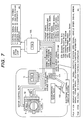
- Fig.7 is a constitution diagram of an engine control system to which the motor driving type throttle apparatus according to the embodiment is applied (the system is applied also to the first embodiment), first, an explanation will be given of the system constitution.
- a module of the engine control system is divided by a plural number in order to alleviate burden.
- the module is divided into a power train control module (hereinafter, Powertrain Control Module is abbreviated and referred to as PCM) 100 constituting a central engine control unit and the electronic control module (here, may be referred to as TCM by abbreviating Throttle Control Module) 11 for controlling the throttle valve as has been described already.
- PCM 100 inputs various sensor signals of engine rotation number, water temperature, cruise control signal, brake signal, clutch position signal, vehicle speed sensor signal. And PCM 100 calculates a fuel system control signal, an ignition system control signal and a peripheral apparatus control signal.
- PCM 100 inputs a position signal of an accelerator pedal 102 from a accelerator pedal position sensor (hereinafter, in this case, Accelerator Pedal Position Sensor is abbreviated and is referred to as APPS) 101.
- APPS Accelerator Pedal Position Sensor
- PCM 100 calculates target instruction throttle position signal (target opening degree signal of the throttle valve) based on the vehicle speed signal and the like. PCM 100 transmits said accelerator position signal and said target instruction signal to TCM 11 by serial communication or parallel communication.
- TCM 11 inputs the target opening degree instruction signal and an really opening degree signal of the throttle position sensor (Throttle Position Sensor may be abbreviated and referred to as TPS) 9, and controls the motor 3 by duty control such that the throttle valve 2 is provided with the set opening degree.
- TPS throttle Position Sensor
- TCM 11 inputs the APPS signal, the vehicle speed signal, the break signal, the cruise signal and so on via PCM 100. And TCM11 self-diagnoses whether the throttle control system is abnormal in view of relationships between these signals and the TPS signal.
- PCM 100 is also inputs the TPS signal (throttle valve opening degree signal) from TCM 11, and self-diagnoses whether normal control operation is carried out based thereon.
- TPS signal throttle valve opening degree signal
- the fail-safe is achieved by transmitting information of the above self-diagnosing, mentioned above, to counterpart sides (monitoring PCM and TCM by each other).
- TCM 11 is provided integrally with APPS 101, for example, on the side of the accelerator pedal system in consideration of temperature environment, influence of space or the like. According to the embodiment, by carrying out improvements with regard to heat resistance, heat radiating performance and small-sized formation, TCM is made attachable to the throttle body, particularly, TCM (electronic control module) 11 is made attachable to a cover (for example, gear cover) attached to the throttle body.
- TCM electronic control module
- the TPS is constituted by sensors of a so-to-speak double system which prepares two sensors of the same type in one package. Also with regard to APPS, it is constituted by a double or triple system.
- Fig.8 is a perspective view viewed by removing the cover 10 from the throttle body 1 of the embodiment.
- the cover 10 is attached to cover a containing portion 110 of a throttle valve mechanism formed at a side wall of the body 1, in order to protect throttle valve related parts such as the throttle valve shaft 8, the reduction gear mechanism 4, the motor 3 and so on.
- the motor (throttle actuator) 3 and the gear mechanism (power transmission apparatus) 4 are arranged to be protected by the single cover 10, And with regard to the motor 3, as shown in Fig.13, an opening of the motor housing 31 (opening for attaching motor) is formed into the throttle valve mechanism containing portion 110, and an end bracket 3a of the motor 3 is fixed to the opening by screws 111 (Fig.8).
- the motor terminal 33 provided at the end bracket 3a is arranged to direct to the side of the cover 10 at a vicinity of a side of a trim 112 in the throttle valve mechanism containing portion 110.
- the motor 3 is driven in accordance with the accelerator signal related to an amount of depressing the accelerator pedal and traction signal.
- the power of the motor 3 is transmitted to the throttle valve shaft 8 via the gears 5, 6 and 7.
- the gear 7 is fixed to the throttle valve shaft 8 ,and is a fan-shaped gear, and is engaged with the lever 24 which is fitted freely to throttle valve shaft 8 to attract each other via a spring B25.
- a spring A23 is a return spring of the throttle valve, one end thereof is locked by a spring locking portion 113 provided at the body 1, and other end is locked by the lever 24.
- the default opening degree setting mechanism is for maintaining an initial opening degree of the throttle valve to be larger than a fully close control position of the throttle valve, when an engine key is made OFF (in other words, when the electric actuator 3 does not drive). From the default opening degree position to a fully open control position, the throttle valve opening degree is determined by balance between motor power and the spring A (return spring) 25. When the throttle valve opening degree is controlled to be smaller than default opening degree, the movement of the lever 24 is restricted by a default opening degree stopper (not illustrated) , and only the gear 7 and the throttle valve shaft 8 are turned round to the fully closed direction against the force of the spring B25. Notation 114 designates a fully closed stopper, and the fully close position is determined by bringing one side of the fan -shaped gear 7 into contact with said stopper 114.
- a significant characteristic of the cover 10 according to the embodiment resides in that the electronic control module 11 or so-to-speak TCM 11 for controlling the throttle valve is attached to the cover 10. Therefore, there is not provided the module housing 41 as in the first embodiment.
- Fig.9 is a perspective view viewing the cover of Fig.8 from the inner side
- Fig.10 is a plane view viewing the cover of Fig.8 from the inner side.
- the electronic control module 11 is not seen by being covered by a module cover 130, however, when the module cover 130 is removed, as shown in Fig.15, at the inner face of the cover 10, the electronic control module 11 is seen attached in a containing portion 10B thereof. Further, at the inner face of the cover 10, the throttle position sensor 9 is attached contiguous to the electronic control module 11.
- Terminals 91 through 96 of the throttle position sensor 9 are directed to one side of the electronic control module 11, and connected to terminals 121 through 126 of the electronic control module.
- the throttle position sensor of the embodiment is constituted by sensors of a double system as has been described above.
- Numerals 91 through 93 designate a ground terminal, an input terminal and an output terminal of one system.
- numerals 94 through 96 designate a ground terminal, an input terminal and an output terminal of other system.
- Fig. 17 is a perspective view showing the structure of the inner face of the cover 10 before attaching the throttle position sensor and the electronic control module.
- a containing portion of the throttle position sensor 9 (throttle position sensor housing) 10A the containing portion of the electronic control module 11 (module housing) 10B and an intermediary connector portion 10C for connecting with the motor terminal 33 of the motor (electric actuator) 3.
- an outer face of the cover 10 there is formed an external connecting connector portion 10D of the electronic control module 11.
- All of the containing portions 10A, 10B and the intermediary connector portion 10C, are arranged contiguously each other in order to be contained compactly at the inner side of the cover 10.
- the throttle position sensor containing portion 10A is arranged on one side and the intermediary connector portion 10C is arranged on other side by interposing the module containing portion 10B.
- the intermediary connector portion 10C is constituted by molding a connector housing 10C' at an inner face of a side wall of one side of the cover 10 integrally with the cover and insert-molding a terminal 15 (refer to Fig.13) for motor connection in the connector housing 10C' by,
- One end of the terminal 15 is disposed at a terminal insertion hole 10C'' and is connected to the motor terminal 33 via an intermediary metal piece 16 (Fig. 13, Fig. 19) inserted into the hole 10C'', when the cover 10 is attached to the throttle body 1.
- a group of lead frames 131 through 150 for being connected with terminals 141 through 160 of the circuit board of the electronic control module 11 is insert-molded (embedded) with an aligned arrangement.
- the ends of the lead frames on one side are exposed at positions contiguous to one side of the electronic control module containing portion 10B at the inner face of the cover 10. And as shown in Fig. 12, ends thereof on other side constitute connecter pins 131' through 150' in the outside connecting connector portion (connector case) 10D.
- the connector pins 131' through 150' are arranged in two rows by being divided into odd number numerals 131', 133'...149' and even number numerals 132', 134'...150' of notations for providing compact formation of the connector case.
- the lead frames 131 through 150 formed by such frame shape.
- the group of terminals 131 through 150 is connected to a cable connector on the side of PCM 100.
- the group is constituted by terminals for inputting battery power source, ground thereof, output signals from PCM (communication input, cruise signal, vehicle speed signal, accelerator pedal signal, etc. ) and terminals for outputting the throttle position (valve opening degree) signal and the communication signal from TCM 11 to PCM 100.
- the lead frames 131 through 150 can be connected to the group of terminals 141 through 160 provided at the circuit board of the electronic control module 11 without being dotted with them in the cover.
- the throttle position sensor 9 is packaged unit style, previously completed as an assembly before integrating into the cover 10, and attached to the containing portion 10A as the unit, and accordingly attachment thereof is convenient.
- an engaging hole 9B for inserting one end 8' of the throttle valve shaft is formed at a central position of the packaged unit.
- the throttle position sensor (packaged unit) is provided with at least two pieces of positioning attaching holes 9C, meanwhile, positioning pins 10E fitted to the attaching holes 9c are arranged at the throttle position sensor containing portion 10A.
- the positioning pins 10E are constituted by resin members integrally molded with the cover 10, and thermally welded to the attaching holes 9c after having been fitted thereto. Therefore, the throttle position sensor 9 is attached by so-to-speak thermal fastening.
- two resistors (dual resistors) 92 which constitute two potentiometers are formed on inner face of a side wall 9A of the package combined with the package elements 90 and 91.
- a movable conductor (rotor) 93 in contact with the resistors 92 is integrated in the package.
- An elastic piece 94 for receiving the one end 8' of the throttle valve shaft is arranged at the rotor center, and a ring-like spring 95 is fitted to the outer periphery of the elastic piece 94.
- a blocking wall 10F for partitioning between a space of the module containing portion 10B and a space of the throttle position sensor containing portion 10A.
- a notch 10G for fitting with one end of the terminal side (terminal base) 9D of the throttle position sensor 9 (refer to Fig.16).
- the terminal base 9D is fitted to the notch 10G in an airtight state.
- the module containing portion 10B is charged with a gel for preventing the module from humidity. The gel is prevented from being flowed out owing to the airtight fitting of the blocking wall 10F and the terminal base 9D.
- the notch 10G of the blocking wall 10F is formed with a trapezoidal-shaped fitting groove 10G' extend toward the opening.
- the terminal base 9D is formed with a trapezoidal plate 9E having a shape similar to the fitting groove 10G'.
- the fitting groove 10G' is fitted with the trapezoidal plate 9E by coating an adhesive agent, thereby constitute the above-described airtight fitting structure.
- the trapezoidal fitting structure By constituting the trapezoidal fitting structure in this way, the airtight structure is guaranteed without scraping off the adhesive agent, when the trapezoidal plate 9E is fitted to the fitting groove 10G'.
- the hemming of the cover 10 is formed with a groove 165 fitted with a seal 164.
- Numeral 167 designates a cover attaching hole which is matched with a hole 168 on the side of the throttle body. The cover is fastened by a rivet or a screw as shown in numeral 169 via hole 167 and 168.
- Fig. 20 is a perspective view completely disassembling the embodiment article.
- the throttle position sensor unit and the electronic control module can simply be attached to the cover of the throttle valve mechanism.
- the electronic control module and the throttle position sensor can be aggregated and attached to the throttle valve mechanism cover (space saving formation).
- the cover can be provided with harnesses and connectors of the electronic control module, the motor power source, the throttle position sensor and so on in simplified formation and shortened formation.
- the harness can be insert-molded integrally with the resin cover, further, by achieving rationalization of an amount of the harness, a reduction in fabrication cost can be achieved.
- a total of the throttle apparatus is made compact, which facilitates mounting and integration to an engine.
- the module cover 130 although the module cover is molded by a synthetic resin, the module cover may be made of a metal in place thereof. An embodiment thereof is shown by Figs.21 and 22.
- the module cover 130 is made of aluminum and the following heat sink structure is adopted.
- the electronic control module 11 has a plate 46 for holding the circuit board 11' and the module cover 130 other than the circuit board (module main body) 11' for control.
- the plate 46 is molded by excellent thermally conductive material.
- the module cover 130 is molded by an excellent thermally conductive material and covers the circuit board 11' above the plate 46.
- the plate 46 and the module cover 130 are brought into contact with each other via a thermally conductive member 162.
- the module cover 130 is brought into contact with the throttle body 1 molded by an excellent thermally conductive material via the thermally conductive member 34.
- the thermally conductive member 34 utilizes the gear shaft and is constructed by a structure in which the gear shaft 34 is brought into contact with the module cover 130 and the throttle body 1. Further, the thermally conductive member 162 is constituted by the wall portion provided on the plate 46. Further, the throttle body 1, the plate 46, the thermally conductive member 162, the module cover 130 and the thermally conductive member 34 are made of aluminum. The thermally conductive member 162 is formed with the above-described notch 163 for receiving the terminal base of the throttle position sensor 9.
- the reliability of the apparatus can be promoted.
- the motor driving type throttle apparatus by compact formation of shape including the body and the cover, simplified formation of assembling operation, simplified formation of wiring operation substantially capable of omitting external wiring, a reduction in harness amount can be achieved and by promotion of the heat radiating performance, low cost formation of a total of the apparatus, promotion of reliability and mountability and space saving formation can be achieved.
Abstract
Description
- The present invention relates to a motor driving type throttle apparatus.
- Conventionally, a motor driving type throttle apparatus which drives a throttle valve of an internal-combustion engine by an electronic actuator (for example, direct current motor, stepping motor) has been put to practical use.
- A motor driving type throttle apparatus is electronically controlled based on opening degree signal of accelerator pedal or traction control signal, and drives the throttle to make an optimum throttle position (throttle valve opening degree) in accordance with an engine state. For that purpose, a throttle position sensor for detecting the throttle position (opening degree of the throttle valve) is attached to the throttle body.
- Further, the motor driving type throttle apparatus is integrally assembled with an electronic control module, there is disclosed Japanese Translation of Unexamined PCT Application No.508954/1997.
- According to the application, a number of individual members provided to an electronic type engine control system are attached to a sleeve (throttle body) of a throttle apparatus.
- It is described that there are provided for example at least one throttle mechanism operable by a throttle valve driving motor (electric actuator), an electronic controller and a regenerating valve and/or an air flow sensor. These members are contained in a common casing as a pre-assembled constitution unit.
- It is an object of the invention to provide a compact motor driving type throttle apparatus capable of being assembled to an engine with high reliability in a simple style, in which manufacturing cost is inexpensive by simplifying various members generally used conventionally, for example, a cover, electric connection lines and connected portions and so on which are separately provided to a throttle valve, a motor as a drive source, a power transmission apparatus and the like.
- Further, the invention provides a motor driving type throttle apparatus facilitating to arrange an electronic control module and capable of saving space of the formation.
- The present invention proposes the following throttle apparatus in order to achieve the above-described object.
- (1) There is proposed a motor driving type throttle
apparatus constituted by integrating an electronic control
module to said throttle apparatus, in which the apparatus is
integrally formed with a cover for protecting a throttle
actuator (for example, throttle valve driving motor) and a
power transmission apparatus (for example, gear mechanism) and
an electronic module housing.
For example, there is proposed a motor driving type
throttle apparatus characterized by comprising a throttle body
integrally formed with throttle valve housing and a throttle
actuator housing;
wherein a power transmission apparatus for transmitting an output of the throttle actuator to the throttle valve is integrated to the throttle body;
wherein an electronic control module for controlling the throttle valve is contained in a module housing or mounted on a board; and
wherein the throttle actuator and the power transmission apparatus are arranged to be protected by a single cover. Said cover and said module housing or said board are integrally formed.
There may be constituted an apparatus in which the electronic control module serves as the cover. - (2) There is proposed a throttle apparatus in which a throttle position sensor is integrally assembled to the cover formed by an insulating material (the assembling may be carried out by integrating parts of the throttle position sensor directly to the cover, or carried out by a unit style by integrating an assembly, that is, an throttle sensor unit assembled at a preceding step), electric conductors are integrally insert-molded into the cover, and the throttle position sensor and an electronic control module are electrically connected via the conductor.
- (3) Further, there is proposed a throttle apparatus in which when the throttle position sensor and the cover are separately formed (throttle position sensor is unitized before being integrated to the cover), the throttle position sensor unit is integrated to the cover by thermal fastening.
- (4) Further, the throttle position sensor and the conductor may be connected by wire bonding or welding, and intermediary terminals may be provided between the throttle position sensor and the conductor.
- (5) Further, there is proposed an apparatus in which a throttle actuator and a electronic control module are electrically connected via a conductor insert-molded integrally into the cover formed by the insulating material. In this case, the throttle actuator and the conductor are connected by wire bonding or welding.Intermediary terminals may be provided between the throttle actuator and the conductor.
- (6) Further, an air flow meter may be integrated to the
electronic control module. Thereby, there can be achieved no
adjustment formation of output of the air flow meter by learning
by a microcomputer.
For example, the apparatus is characterized in which a
cover for protecting the throttle actuator with the power
transmission apparatus and a module housing for containing an
electronic control module for controlling the throttle valve
are integrally formed;
wherein a board is bonded to the module housing, and the electronic control module is mounted to the board; and
wherein an air flow meter is integrated to the module housing ,and the electronic control module is disposed on an upper side of the air flow meter. - (7) Further, there is proposed a constitution in which the electronic control module is arranged in an orthogonal direction to the air flow meter housing. The present invention proposes the following other constitution.
- (8) There is provided a motor driving type throttle apparatus characterized in which a cover for covering one end side of a throttle valve shaft is attached to a side wall of a throttle body having a throttle valve, and an electronic control module for controlling the throttle valve is attached to the cover.
- (9) Further, there is provided the throttle apparatus in which an inner face of the cover is attached with an electronic control module for controlling the throttle valve and a throttle position sensor for detecting a position (opening degree) of the throttle valve contiguous to each other. The terminals of the throttle position sensor are directed to a side of the electronic control module, and connected with terminals of the electronic control module.
- (10) Further, there is proposed a throttle apparatus in which an inner face of said cover is formed with a throttle position sensor housing and an electronic control module housing and an intermediary connector for connecting to motor terminals of the electric actuator. An outer face of the cover is formed with a connector for external connection of the electronic control module.
- (11) Further, in relation thereto, there is proposed a
throttle apparatus in which the throttle position sensor and
the electronic control module integrally attached to the inner
face of said cover. The throttle position sensor and the
electronic control module are contiguous to each other and
connected. The connector for external connection of the
electronic control module is mounted at said cover, ends on
one side of a group of lead frames constituting terminals of
the connector are arranged to align along one side of an inner
side of the cover and connected to a group of terminals provided
at a circuit board of the electronic control module;
wherein power source is supplied to the electric actuator via a connector for external connection and intermediary connectors. Said intermediary are provided at the electronic control module and the cover. - (12) Further, with regard to the intermediary connectors, there is proposed a constitution in which an intermediary terminal housing for containing the intermediary terminals formed with the cover by integral molding, and the intermediary terminals are arranged there.
- (13) Terminals of the throttle position sensor and conductors for electric wiring are connected, the conductors and terminals of the electronic control module are connected by, for example, wire bonding or welding.
- (14) Further, there is proposed the following
constitution as a motor driving type throttle apparatus in
consideration of heat radiating performance.
For example, a resin cover for covering one end side of
the throttle valve shaft is attached to a side wall of the
throttle body, and an electronic control module for controlling
a throttle valve is attached to an inner face of said resin
cover;
wherein the electronic control module has a circuit board for control and a plate formed by an excellent thermally conductive material (for example, made of aluminum)for holding the circuit board and a module cover formed by an excellent thermally conductive material for covering the circuit board on the plate. The plate and the module cover are brought into contact with each other via a thermally conductive member and the module cover is brought into contact with the throttle body formed by an excellent thermally conductive material via a thermally conductive member. -
-
- Fig.1 is a vertical sectional view showing parts assembling of a throttle apparatus according to a first embodiment of the invention;
- Fig.2 is a sectional view taken along a line A-A of Fig.1;
- Fig.3 is a sectional view taken along a line B-B of Fig.1;
- Fig.4 is a plane view of Fig.1;
- Fig.5 is a sectional view of Fig.1;
- Fig.6 is a plane view showing a module cover;
- Fig.7 is a constitution diagram of an engine control system constituting an object of applying the invention;
- Fig.8 is a perspective view viewing a throttle apparatus according to a second embodiment of the invention by removing a cover from a throttle body;
- Fig.9 is perspective view viewing the cover by changing a viewing angle;
- Fig.10 is a plane view viewing the cover from an inner side;
- Fig.11 is a front view of the throttle apparatus;
- Fig.12 is a top view of the throttle apparatus;
- Fig.13 is a sectional view taken along a line A-A of Fig.12;
- Fig.14 is a side view of the cover;
- Fig.15 is a perspective view viewing an inner side of the cover by removing a module cover;
- Fig.16 is a plane view viewing the inner side of the cover by removing the module cover;
- Fig.17 is a perspective view viewing the inner side of the cover by removing a throttle position sensor and an electronic control module;
- Fig.18 is a perspective view of the throttle position sensor;
- Fig.19 is a disassembled perspective view of the cover and parts attached thereto;
- Fig. 20 is a disassembled perspective view of the throttle apparatus;
- Fig.21 is a partial sectional view of a throttle apparatus according to a third embodiment of the invention;
- Fig.22 is a disassembled perspective view of a cover of the throttle apparatus according to the third embodiment and parts attached thereto.
-
- An explanation will be given of an embodiment according to the invention in reference to the drawings as follows.
- In these Fig 1∼Fig 5, a motor driving type throttle apparatus (throttle valve apparatus) is constituted by, as main elements, a throttle body (hereinafter, may simply be referred to as body) 1, a
throttle valve 2, a motor 3 (throttle actuator) for driving thethrottle valve 2, a power transmission apparatus 4, a throttle position sensor (throttle valve opening degree meter ) 9 provided at athrottle valve shaft 8 for measuring a position of throttle valve 12 (opening degree of the throttle valve 2), acover 10 for protecting thethrottle valve 2 · themotors 3 · the power transmission apparatus 4, anelectronic control module 11 and anair flow meter 12. - The
body 1 is constituted by integrally molding a containing portion of the throttle valve 2 (throttle housing or throttle chamber) and a containing portion (motor housing) 31 of themotor 3. Themotor 3 may externally be attached integrally. Therefore, here, the portion is represented as the 'containing' portion including such a mode. - The
throttle valve 2 is provided at an inner portion (air passage) of thebody 1, theshaft 8 is supported bybearings body 1, and one end portion of theshaft 8 is projected to outside of the body. - Further, the projecting portion of the
shaft 8 is guided by a spring A23, alever 24, a spring B25. - Further, the
body 1 is provided with 4 pieces of attachingholes 26. The structure is well known and further explanation is not needed. - The
body 1 contains themotor 3 by themotor housing 31. An axial direction of themotor 3 coincides with a direction of thethrottle valve shaft 8, and amotor shaft 32 is provided with agear 5. Further, themotor 3 is provided with amotor terminal 33. - The
body 1 is provided with agear shaft 34 in a direction the same as the direction of theshaft 8, and agear 6 is rotatably fixed thereto. Further, agear 7 is disposed on a lower side of a gear. At an upper end of thelever 24, theshaft 8 is provided with thegear 7, thegear 5 and thegear 6 mesh together, thegear 6 and thegear 7 mesh together in the illustrated style, thereby these gears constitute the power transmission apparatus 4. Thethrottle valve 2 can be operated to open and close in a decelerated state with the motor 3 (a drive source) by said transmission. - In this way, the power transmission apparatus 4 for transmitting an output of the throttle actuator to the
throttle valve 2, is integrally assembled to thebody 1. - The
cover 10 for protecting thethrottle valve 2, the throttle actuator (motor 3) and the power transmission apparatus (gear mechanism) 4, is integrally molded by resin. In this case, amodule housing 41 for containing theelectronic control module 11 for controllingmotor 3 is integrally molded along with thecover 10. - The
cover 10 is integrally molded with a throttleposition sensor housing 42, and a gear shaft housing. THEhousing 42 contains thethrottle position sensor 9 attached to the one end of theshaft 8. A gear shaft housing contains one end of thegear shaft 34. A throttle valve protectingcover portion 44 and themodule housing 41 are molded with a difference in level as illustrated. - When the
throttle position sensor 9 and thecover 10 are separately molded by resin. And thereafter, thethrottle position sensor 9 is fixed to thecover 10 by thermal tightening. - As the
air flow meter 12, there are known various flow rate meters, although the flow meter is not specified, for example, a hot wire type air flow meter can be adopted. - The
air flow meter 12 is fixedly attached to aplate 46 constituted by aluminum or the like via aflow meter housing 45. Acircuit board 47 of theelectronic control module 11 is mounted on theplate 46. Theplate 46 is adhered to themodule housing 41. According to the embodiment, themodule housing 41 and theplate 46 for mounting theboard 47 are separately molded, and thereafter these are integrated. But as other molding method, themodule housing 41 and theplate 46 can integrally be molded. In the former case (module housing 41 and theplate 46 are separately molded) , the assembling is easy in view of steps of mounting and adhering theelectronic control module 11 onto the board. In latter case (themodule housing 41 and theplate 46 are integrally molded), a number of parts can be reduced. Any of these may be adopted in accordance with design. - As illustrated, the
module housing 41 is disposed above theflow meter 12, theelectronic control module 11 is arranged in a horizontal direction relative to a direction of aflow passage 53 of thethrottle body 1. In this way, the assembling parts is facilitated. Further, by lowering themodule housing 41 relative to the throttle valve protectingcover portion 44 and bringing themodule housing 41 near to the air flow meter 12 ( throttle body 2), it is effective for protecting theelectronic control module 11 against external force such as that in dropping or the like. Thecover 10 is provided with aseal member 48 constituted
By rubber or the like to direct to thebody 1 at the surrounding. - The
flow meter housing 45 is provided with athermometer 51. Thethermometer 51 and theflow meter 12 are arranged in theflow passage 53 via afitting hole 52 provided at thebody 1. - Further, the
body 1 is provided with anair introducing hole 54 conducted to apressure meter 56 to communicate with an air introducing hole 55 provided at theflow meter housing 45. Pressure of theflow passage 53 is measured by thepressure meter 56 which is provided at theelectronic control module 11. - In this way, the
electronic control module 11 is integrated with theflow meter 12, thethermometer 51 and thepressure meter 56. - According to such a constitution, by integrating the flow meter to the electronic control module, no adjustment formation of flow meter output can be achieved by learning by a microcomputer, further, by omitting harness and connector, there can be achieved 1) low cost formation, 2) promotion of reliability, 3) space saving formation, 4) connector aggregation and 5) assembly simplification.
- In molding a
gear cover 60 of thecover 10,motor wiring 61 andwiring 62 for thethrottle position sensor 9, as conductors, are integrally molded and integrated to inner portions of the cover. - The
gear cover 60 is formed with an intermediate terminal housing 71, and anintermediate terminal 72 is contained therein. Thereby, amotor terminal 33 is electrically connected to themotor wiring 61 via theintermediate terminal 72. Thethrottle position sensor 9 and its wiring 62 (conductor) are bonded by wire bonding or welded by way of an intermediate terminal, or directly not by way of the intermediate terminal. Further, the same goes with between thewiring 62 and theelectronic control module 11. Connecting portions of these are designated bynumerals - The throttle actuator (motor) 3 and the
electronic control module 11 are electrically connected by the motor wiring 61 (conductor) which integrally embedded in thecover 10 molded by insulating material. The throttle actuator and themotor wiring 61 are electrically connected via theintermediate terminal 72. A connecting portion between aconnector 63 and theelectronic control module 11 connected by wire bonding or welding, is designated bynumeral 64. - In this way, the
board 47 is connected to themotor wiring 61 and the throttleposition sensor wiring 62. Amicrocomputer 65 is arranged on theboard 47. Themodule housing 41 is covered by amodule cover 81 to thereby protect theelectronic control module 11. - Next, an explanation will be given of a second embodiment of the invention in reference to Fig.7 through Fig.20.
- Fig.7 is a constitution diagram of an engine control system to which the motor driving type throttle apparatus according to the embodiment is applied (the system is applied also to the first embodiment), first, an explanation will be given of the system constitution.
- According to the engine control system of Fig.7, a module of the engine control system is divided by a plural number in order to alleviate burden. For example, the module is divided into a power train control module (hereinafter, Powertrain Control Module is abbreviated and referred to as PCM) 100 constituting a central engine control unit and the electronic control module (here, may be referred to as TCM by abbreviating Throttle Control Module) 11 for controlling the throttle valve as has been described already.
PCM 100 inputs various sensor signals of engine rotation number, water temperature, cruise control signal, brake signal, clutch position signal, vehicle speed sensor signal. AndPCM 100 calculates a fuel system control signal, an ignition system control signal and a peripheral apparatus control signal. - Further,
PCM 100 inputs a position signal of anaccelerator pedal 102 from a accelerator pedal position sensor (hereinafter, in this case, Accelerator Pedal Position Sensor is abbreviated and is referred to as APPS) 101. -
PCM 100 calculates target instruction throttle position signal (target opening degree signal of the throttle valve) based on the vehicle speed signal and the like.PCM 100 transmits said accelerator position signal and said target instruction signal toTCM 11 by serial communication or parallel communication. -
TCM 11 inputs the target opening degree instruction signal and an really opening degree signal of the throttle position sensor (Throttle Position Sensor may be abbreviated and referred to as TPS) 9, and controls themotor 3 by duty control such that thethrottle valve 2 is provided with the set opening degree. - Other than these,
TCM 11 inputs the APPS signal, the vehicle speed signal, the break signal, the cruise signal and so on viaPCM 100. And TCM11 self-diagnoses whether the throttle control system is abnormal in view of relationships between these signals and the TPS signal. -
PCM 100 is also inputs the TPS signal (throttle valve opening degree signal) fromTCM 11, and self-diagnoses whether normal control operation is carried out based thereon. - Further, the fail-safe is achieved by transmitting information of the above self-diagnosing, mentioned above, to counterpart sides (monitoring PCM and TCM by each other).
-
Conventional TCM 11 is provided integrally withAPPS 101, for example, on the side of the accelerator pedal system in consideration of temperature environment, influence of space or the like. According to the embodiment, by carrying out improvements with regard to heat resistance, heat radiating performance and small-sized formation, TCM is made attachable to the throttle body, particularly, TCM (electronic control module) 11 is made attachable to a cover (for example, gear cover) attached to the throttle body. - Here, with respect to the TPS signal (throttle valve opening degree signal), a spare can be arranged in consideration of accidental failure. Therefore, the TPS is constituted by sensors of a so-to-speak double system which prepares two sensors of the same type in one package. Also with regard to APPS, it is constituted by a double or triple system.
- Next, an explanation will be given of a throttle apparatus according to the embodiment. Further, in the drawings, parts the same as those in the embodiment described above, indicate the same or common elements.
- Fig.8 is a perspective view viewed by removing the
cover 10 from thethrottle body 1 of the embodiment. - The
cover 10 is attached to cover a containingportion 110 of a throttle valve mechanism formed at a side wall of thebody 1, in order to protect throttle valve related parts such as thethrottle valve shaft 8, the reduction gear mechanism 4, themotor 3 and so on. - That is, the motor (throttle actuator) 3 and the gear mechanism (power transmission apparatus) 4 are arranged to be protected by the
single cover 10, And with regard to themotor 3, as shown in Fig.13, an opening of the motor housing 31 (opening for attaching motor) is formed into the throttle valvemechanism containing portion 110, and an end bracket 3a of themotor 3 is fixed to the opening by screws 111 (Fig.8). - The
motor terminal 33 provided at the end bracket 3a is arranged to direct to the side of thecover 10 at a vicinity of a side of a trim 112 in the throttle valvemechanism containing portion 110. - The
motor 3 is driven in accordance with the accelerator signal related to an amount of depressing the accelerator pedal and traction signal. The power of themotor 3 is transmitted to thethrottle valve shaft 8 via thegears - The
gear 7 is fixed to thethrottle valve shaft 8 ,and is a fan-shaped gear, and is engaged with thelever 24 which is fitted freely to throttlevalve shaft 8 to attract each other via a spring B25. - A spring A23 is a return spring of the throttle valve, one end thereof is locked by a
spring locking portion 113 provided at thebody 1, and other end is locked by thelever 24. - These springs A23 and B25 and the
lever 24 are used to constitute a so-to-speak a default opening degree setting mechanism which has already been known publicly. - The default opening degree setting mechanism is for maintaining an initial opening degree of the throttle valve to be larger than a fully close control position of the throttle valve, when an engine key is made OFF (in other words, when the
electric actuator 3 does not drive). From the default opening degree position to a fully open control position, the throttle valve opening degree is determined by balance between motor power and the spring A (return spring) 25. When the throttle valve opening degree is controlled to be smaller than default opening degree, the movement of thelever 24 is restricted by a default opening degree stopper (not illustrated) , and only thegear 7 and thethrottle valve shaft 8 are turned round to the fully closed direction against the force of the spring B25.Notation 114 designates a fully closed stopper, and the fully close position is determined by bringing one side of the fan -shapedgear 7 into contact with saidstopper 114. - An explanation will be given here of the
cover 10. - A significant characteristic of the
cover 10 according to the embodiment resides in that theelectronic control module 11 or so-to-speakTCM 11 for controlling the throttle valve is attached to thecover 10. Therefore, there is not provided themodule housing 41 as in the first embodiment. - Fig.9 is a perspective view viewing the cover of Fig.8 from the inner side, and Fig.10 is a plane view viewing the cover of Fig.8 from the inner side. In these drawings, the
electronic control module 11 is not seen by being covered by amodule cover 130, however, when themodule cover 130 is removed, as shown in Fig.15, at the inner face of thecover 10, theelectronic control module 11 is seen attached in a containingportion 10B thereof. Further, at the inner face of thecover 10, thethrottle position sensor 9 is attached contiguous to theelectronic control module 11. -
Terminals 91 through 96 of thethrottle position sensor 9 are directed to one side of theelectronic control module 11, and connected toterminals 121 through 126 of the electronic control module. The throttle position sensor of the embodiment is constituted by sensors of a double system as has been described above.Numerals 91 through 93 designate a ground terminal, an input terminal and an output terminal of one system. Andnumerals 94 through 96 designate a ground terminal, an input terminal and an output terminal of other system. - Fig. 17 is a perspective view showing the structure of the inner face of the
cover 10 before attaching the throttle position sensor and the electronic control module. Explaining of the structure of the inner face of thecover 10, at the inner face of thecover 10, there are formed a containing portion of the throttle position sensor 9 (throttle position sensor housing) 10A, the containing portion of the electronic control module 11 (module housing) 10B and anintermediary connector portion 10C for connecting with themotor terminal 33 of the motor (electric actuator) 3. On the other hand, at an outer face of thecover 10, there is formed an external connecting connector portion 10D of theelectronic control module 11. - All of the containing
portions intermediary connector portion 10C, are arranged contiguously each other in order to be contained compactly at the inner side of thecover 10. The throttle positionsensor containing portion 10A is arranged on one side and theintermediary connector portion 10C is arranged on other side by interposing themodule containing portion 10B. - The
intermediary connector portion 10C is constituted by molding aconnector housing 10C' at an inner face of a side wall of one side of thecover 10 integrally with the cover and insert-molding a terminal 15 (refer to Fig.13) for motor connection in theconnector housing 10C' by, - One end of the terminal 15 is disposed at a
terminal insertion hole 10C'' and is connected to themotor terminal 33 via an intermediary metal piece 16 (Fig. 13, Fig. 19) inserted into thehole 10C'', when thecover 10 is attached to thethrottle body 1. - As shown in Fig.15 and Fig.16, other ends 15A of the
terminals 15 project from left and right side faces of theconnector housing 10C' to the inner portion of thecover 10, and theends 15A and powersource output terminals 17 are connected bywire bondings 18. The connection may be carried out by extending the terminals to overlap each other and directly bonding the terminals. - Further, at the cover 10 (resin mold), a group of
lead frames 131 through 150 for being connected withterminals 141 through 160 of the circuit board of theelectronic control module 11 is insert-molded (embedded) with an aligned arrangement. - The ends of the lead frames on one side are exposed at positions contiguous to one side of the electronic control
module containing portion 10B at the inner face of thecover 10. And as shown in Fig. 12, ends thereof on other side constitute connecter pins 131' through 150' in the outside connecting connector portion (connector case) 10D. The connector pins 131' through 150', are arranged in two rows by being divided into odd number numerals 131', 133'...149' and even number numerals 132', 134'...150' of notations for providing compact formation of the connector case. The lead frames 131 through 150 formed by such frame shape. - The group of
terminals 131 through 150 is connected to a cable connector on the side ofPCM 100. For example, the group is constituted by terminals for inputting battery power source, ground thereof, output signals from PCM (communication input, cruise signal, vehicle speed signal, accelerator pedal signal, etc. ) and terminals for outputting the throttle position (valve opening degree) signal and the communication signal fromTCM 11 toPCM 100. - As described above, by attaching the
electronic control module 11 to the inner face of thecover 10, further, providing the connector portion 10D for external connection to thecover 10, insert-forming lead frames 131 through 150 constituting terminals thereof, further, bringing to align ends of the group of lead frames on one side along one side on the inner side of the cover, the lead frames 131 through 150 can be connected to the group ofterminals 141 through 160 provided at the circuit board of theelectronic control module 11 without being dotted with them in the cover. - Further, with regard to power source supply to the
motor 3, power is supplied via the external connecting connector portion 10D, and theintermediary connector 10C provided at thecover 10 and theelectronic control module 11. Therefore, it is not necessary to be dotted with the lead frame for power source in thecover 10, and rationalization of electric wirings (shortening and simplifying of connecting operation) can be achieved. - The
throttle position sensor 9 is packaged unit style, previously completed as an assembly before integrating into thecover 10, and attached to the containingportion 10A as the unit, and accordingly attachment thereof is convenient. - As the
throttle position sensor 9, an engaginghole 9B for inserting one end 8' of the throttle valve shaft is formed at a central position of the packaged unit. - Further, in order to improve positioning accuracy of the
throttle position sensor 9 relative to thethrottle valve shaft 8, the throttle position sensor (packaged unit) is provided with at least two pieces of positioning attachingholes 9C, meanwhile, positioning pins 10E fitted to the attaching holes 9c are arranged at the throttle positionsensor containing portion 10A. - The positioning pins 10E are constituted by resin members integrally molded with the
cover 10, and thermally welded to the attaching holes 9c after having been fitted thereto. Therefore, thethrottle position sensor 9 is attached by so-to-speak thermal fastening. - As shown in Fig. 13, at the
throttle position sensor 9, two resistors (dual resistors) 92 which constitute two potentiometers are formed on inner face of aside wall 9A of the package combined with thepackage elements resistors 92 is integrated in the package. Anelastic piece 94 for receiving the one end 8' of the throttle valve shaft is arranged at the rotor center, and a ring-like spring 95 is fitted to the outer periphery of theelastic piece 94. - When the
cover 10 is attached to thethrottle body 1 by screws orrivets 161, the one end 8' of the throttle valve shaft is inserted into the engaginghole 9B while pushing away the elastic piece 94.Therotor 93 is engaged with the one end of the throttle valve shaft without shaky by the fastening force of the ring-like spring 95. - As shown in Fig.17, at the inner face of the
cover 10, there is formed a blocking wall 10F for partitioning between a space of themodule containing portion 10B and a space of the throttle positionsensor containing portion 10A. At the blocking wall 10F, there is formed anotch 10G for fitting with one end of the terminal side (terminal base) 9D of the throttle position sensor 9 (refer to Fig.16). When thethrottle position sensor 9 is set to the containingportion 10A, the terminal base 9D is fitted to thenotch 10G in an airtight state. After attaching theelectronic control module 11, themodule containing portion 10B is charged with a gel for preventing the module from humidity. The gel is prevented from being flowed out owing to the airtight fitting of the blocking wall 10F and the terminal base 9D. - According to the embodiment, the
notch 10G of the blocking wall 10F is formed with a trapezoidal-shapedfitting groove 10G' extend toward the opening. - AT the throttle position sensor, as shown in Fig 18, the terminal base 9D is formed with a
trapezoidal plate 9E having a shape similar to thefitting groove 10G'. - The
fitting groove 10G' is fitted with thetrapezoidal plate 9E by coating an adhesive agent, thereby constitute the above-described airtight fitting structure. By constituting the trapezoidal fitting structure in this way, the airtight structure is guaranteed without scraping off the adhesive agent, when thetrapezoidal plate 9E is fitted to thefitting groove 10G'. Further, the hemming of thecover 10 is formed with agroove 165 fitted with aseal 164.Numeral 167 designates a cover attaching hole which is matched with ahole 168 on the side of the throttle body. The cover is fastened by a rivet or a screw as shown innumeral 169 viahole - Fig. 20 is a perspective view completely disassembling the embodiment article.
- According to the embodiment, there are achieved the following advantages. The throttle position sensor unit and the electronic control module can simply be attached to the cover of the throttle valve mechanism.
- By only attaching the cover to the throttle body, the motor terminal and the intermediary terminal on the cover side are spontaneously connected. Further, the electronic control module and the throttle position sensor can be aggregated and attached to the throttle valve mechanism cover (space saving formation). The cover can be provided with harnesses and connectors of the electronic control module, the motor power source, the throttle position sensor and so on in simplified formation and shortened formation. Particularly with regard to the harness, the harness can be insert-molded integrally with the resin cover, further, by achieving rationalization of an amount of the harness, a reduction in fabrication cost can be achieved.
A total of the throttle apparatus is made compact, which facilitates mounting and integration to an engine.
Further, with regard to themodule cover 130, although the module cover is molded by a synthetic resin, the module cover may be made of a metal in place thereof. An embodiment thereof is shown by Figs.21 and 22. - According to the embodiment, in order to promote heat radiating performance of the
electronic module 11 in thecover 10, themodule cover 130 is made of aluminum and the following heat sink structure is adopted. - As shown in Fig.21 and Fig.22, the
electronic control module 11 has aplate 46 for holding the circuit board 11' and themodule cover 130 other than the circuit board (module main body) 11' for control. Theplate 46 is molded by excellent thermally conductive material. Themodule cover 130 is molded by an excellent thermally conductive material and covers the circuit board 11' above theplate 46. Theplate 46 and themodule cover 130 are brought into contact with each other via a thermallyconductive member 162. Themodule cover 130 is brought into contact with thethrottle body 1 molded by an excellent thermally conductive material via the thermallyconductive member 34. - According to the embodiment, the thermally
conductive member 34 utilizes the gear shaft and is constructed by a structure in which thegear shaft 34 is brought into contact with themodule cover 130 and thethrottle body 1.
Further, the thermallyconductive member 162 is constituted by the wall portion provided on theplate 46. Further, thethrottle body 1, theplate 46, the thermallyconductive member 162, themodule cover 130 and the thermallyconductive member 34 are made of aluminum. The thermallyconductive member 162 is formed with the above-describednotch 163 for receiving the terminal base of thethrottle position sensor 9. - According to the embodiment, other than achieving an effect similar to that of the second embodiment, in the motor driving type throttle apparatus by giving a consideration to the heat radiating performance of the electronic control module mounted to the cover of the throttle body, the reliability of the apparatus can be promoted.
- As described above, according to the invention, in the motor driving type throttle apparatus, by compact formation of shape including the body and the cover, simplified formation of assembling operation, simplified formation of wiring operation substantially capable of omitting external wiring, a reduction in harness amount can be achieved and by promotion of the heat radiating performance, low cost formation of a total of the apparatus, promotion of reliability and mountability and space saving formation can be achieved.
Claims (19)
- A motor driving type throttle apparatus characterized in that a cover (10) for covering one end of a throttle valve shaft (8) is attached to a side wall of a throttle body (1) having a throttle valve (2), and an electronic control module (11) for controlling the throttle valve (2) is attached to said cover (10).
- The motor driving type throttle apparatus according to claim 1, wherein
an inner face of said cover (10) is attached with said electronic control module (11) for controlling the throttle valve (2) and a throttle position sensor (9) for detecting an opening degree of the throttle valve (2) contiguous to each other, and terminals (91-96) of said throttle position sensor (9) are directed to a side of the electronic control module (11) and connected to terminals (121-126) of said electronic control module (11). - The motor driving type throttle apparatus according to claim 1 or 2, wherein
said inner face of said cover (10) is formed with a containing portion of said throttle position sensor (9) for detecting an opening degree of the throttle valve (2), a containing portion of the electronic control module (11) and an intermediary connector portion for connecting to motor terminals of the electronic actuator (3),
and an outer face of the cover (10) is formed with a connector portion (10D) for external connection of said electronic control module (11). - The motor driving type throttle apparatus according to at least one of claims 1 to 3, wherein
the throttle position sensor (9) and the electronic control module (11) are contiguous to each other and connected at a position contiguous thereto;
said cover (10) is provided with a connector portion for external connection of the electronic control module (11), ends of a group of lead frames (131-150) constituting terminals of the connector portion are arranged to align along one side of an inner side of said cover (10) and connected to a group of terminals (141-160) provided at said electronic control module (11); and
a power source is supplied to said electric actuator (3) via said connector portion (10D) for external connection, said electronic control module (11) and intermediary connectors are provided to said cover (10). - The motor driving type throttle apparatus according to at least one of claims 1 to 4, wherein
said cover (10) is a resin cover and said electronic control module (11) is attached with an inner face of the resin cover; and
said electronic control module (11) comprises a circuit board (47) for control, a plate (46) formed by an excellent thermally conductive material holding the circuit board (47) and a module cover (81, 130) formed by an excellent thermally conductive material for covering the circuit board (47) above the plate (46), said plate (46) and said module cover (81) are brought into contact together via a thermally conductive member, and said module cover (81, 130) is brought into contact with the throttle body (1) formed by an excellent thermally conductive material via a thermally conductive member. - The motor driving type throttle apparatus according to at least one of claims 1 to 5, wherein a thermometer (51) is integrated to said electronic control module (11).
- The motor driving type throttle apparatus according to at least one of claims 1 to 6, wherein a pressure meter (56) for detecting pressure of said intake air passage (53) is integrated to said electronic control module (11).
- The motor driving type throttle apparatus according to at least one of claims 1 to 7, wherein the inner face of said cover (10) is formed with a blocking wall (10F) for partitioning between a containing space of said electronic control module (11) and a containing space of said throttle position sensor (9), the blocking wall (10F) is provided with a notch (10G), and one end on a terminal side of said throttle position sensor (9) is fitted to said notch (10G) in an airtight state, thereby constructing a structure in which gel filled in said electronic control module (11) containing portion is prevented from flowing out.
- The motor driving type throttle apparatus according to at least one of claims 1 to 8, wherein said cover (10) is integrally molded with connector portions for external connection of the electronic control module (11).
- The motor driving type throttle apparatus according to at least one of claims 1 to 9,
wherein a resin mold constituting said cover (10) has said group of lead frames (131-150) for connecting to terminals (141-160) of said circuit board of said electronic control module (11), these lead frames (131-150) are embedded into said cover with an aligning arrangement, and ends of said lead frames (131-150) on one side are exposed at positions contiguous to one side of an electronic control module (11) containing portion at an inner face of said cover (10), and ends on other side of said lead frames (131-150) constitute connector pins (131'-150') in a connector case of the connector portion (10D) for external connection. - The motor driving type throttle apparatus according to at least one of claims 1 to 10, wherein said throttle position sensor (9) is attached to an inner face of a resin cover for covering one end of a throttle valve shaft (8) by a packaged unit style.
- The motor driving type throttle apparatus according to at least one of claims 1 to 11, wherein a unit of said throttle position sensor (9) is provided with at least two pieces of positioning attaching holes (9C).
- The motor driving type throttle apparatus according to at least one of claims 1 to 12, wherein said throttle position sensor (9) is thermally fastened by welding a resin member provided at the cover (10).
- The motor driving type throttle apparatus according to at least one of claims 1 to 13, wherein the containing portion of the throttle position sensor (9) is arranged on one side, and the intermediary connector portion (10C) is arranged on other side by interposing said containing portion of the electronic control module (11).
- The motor driving type throttle apparatus according to at least one of claims 1 to 14,
wherein the intermediary connector portion (10C) comprises a connector housing (10C') in a box-like shape integrally molded with said cover (10) and terminals for motor connection integrated with a resin mold of said connector housing (10C') on an inner side of said cover (10),
end portions of the terminals on a side opposed to a side connected with the motor terminals are exposed at an inner portion of said cover (10), and said exposed end portions are connected to power source output terminals provided at the electronic control module (11). - The motor driving type throttle apparatus according to at least one of claims 1 to 15, wherein the throttle body (1), the plate (46) and the module cover (81) are made of aluminum.
- The motor driving type throttle apparatus according to at least one of claims 1 to 16, wherein said throttle body (1) is integrally formed with a throttle valve housing and a throttle actuator housing;
wherein a power transmission apparatus (4) for transmitting an output of the throttle actuator (3) to the throttle valve (2) is integrated to said throttle body (1);
wherein said cover (10) for protecting said throttle actuator (3) and said power transmission apparatus (4), and a module housing (41) for containing said electronic control module (11) for controlling said throttle valve (2), and said cover (10) and said module housing (41) are integrally formed;
wherein said board (47) is bonded to the module housing (41), and the electronic control module (11) is mounted to said board (47); and
wherein an air flow meter (12) is integrated to said module housing (41), and said electronic control module (11) is disposed on an upper side of said air flow meter (12). - The electronic type throttle apparatus according to at least one of claims 1 to 17, wherein a difference in level is provided between said cover (10) and said module housing (41), thereby said module housing (41) is brought neat to said throttle body (1).
- The motor driving type throttle apparatus according to at least one of claims 1 to 18,
wherein said throttle body (1) has said electronic control module (11) for controlling said throttle actuator (3), and said air flow meter (12) is provided for detecting air rate flow in an intake air passage (53);
wherein said cover (10) is a single cover, and
said electronic control module (11) is integrally embedded in said cover (10) and is arranged along the main air flow direction in an intake air passage (53) of said throttle body (1).
Applications Claiming Priority (3)
| Application Number | Priority Date | Filing Date | Title |
|---|---|---|---|
| JP8685999 | 1999-03-29 | ||
| JP8685999 | 1999-03-29 | ||
| EP00902137A EP1167724B1 (en) | 1999-03-29 | 2000-02-08 | Electronically controlled throttle device |
Related Parent Applications (2)
| Application Number | Title | Priority Date | Filing Date |
|---|---|---|---|
| EP00902137.9 Division | 2000-02-08 | ||
| EP00902137A Division EP1167724B1 (en) | 1999-03-29 | 2000-02-08 | Electronically controlled throttle device |
Publications (3)
| Publication Number | Publication Date |
|---|---|
| EP1450022A2 true EP1450022A2 (en) | 2004-08-25 |
| EP1450022A3 EP1450022A3 (en) | 2005-10-05 |
| EP1450022B1 EP1450022B1 (en) | 2007-07-18 |
Family
ID=13898550
Family Applications (2)
| Application Number | Title | Priority Date | Filing Date |
|---|---|---|---|
| EP00902137A Expired - Lifetime EP1167724B1 (en) | 1999-03-29 | 2000-02-08 | Electronically controlled throttle device |
| EP04006975A Expired - Lifetime EP1450022B1 (en) | 1999-03-29 | 2000-02-08 | Motor driving type trhottle apparatus |
Family Applications Before (1)
| Application Number | Title | Priority Date | Filing Date |
|---|---|---|---|
| EP00902137A Expired - Lifetime EP1167724B1 (en) | 1999-03-29 | 2000-02-08 | Electronically controlled throttle device |
Country Status (5)
| Country | Link |
|---|---|
| US (4) | US6725833B1 (en) |
| EP (2) | EP1167724B1 (en) |
| KR (2) | KR20010101959A (en) |
| DE (2) | DE60035622T2 (en) |
| WO (1) | WO2000058614A1 (en) |
Cited By (2)
| Publication number | Priority date | Publication date | Assignee | Title |
|---|---|---|---|---|
| CN102667108A (en) * | 2009-10-06 | 2012-09-12 | 日立汽车系统株式会社 | Circuit module having connector(s) |
| EP3498999A1 (en) * | 2017-12-13 | 2019-06-19 | Continental Automotive GmbH | Valve for an exhaust gas system in a vehicle |
Families Citing this family (63)
| Publication number | Priority date | Publication date | Assignee | Title |
|---|---|---|---|---|
| DE60035622T2 (en) * | 1999-03-29 | 2008-04-10 | Hitachi, Ltd. | Throttle with engine |
| JP3866899B2 (en) * | 2000-04-06 | 2007-01-10 | 株式会社日立製作所 | Throttle valve control device for internal combustion engine and automobile |
| JPWO2002040846A1 (en) * | 2000-11-17 | 2004-03-25 | 株式会社日立製作所 | Intake module for internal combustion engine, member thereof, and electronically controlled throttle device |
| DE10133294A1 (en) * | 2001-07-12 | 2003-01-23 | Siemens Ag | Choke flap port for internal combustion engine has temperature sensor for gaseous medium and pressure sensor for gaseous medium upstream and downstream of choke flap respectively |
| JP3929742B2 (en) * | 2001-10-18 | 2007-06-13 | アルプス電気株式会社 | Throttle valve adjustment unit |
| DE10152252A1 (en) * | 2001-10-20 | 2003-04-30 | Bosch Gmbh Robert | Electronic circuit protection device |
| US7191754B2 (en) * | 2002-03-06 | 2007-03-20 | Borgwarner Inc. | Position sensor apparatus and method |
| DE60322751D1 (en) * | 2002-03-06 | 2008-09-18 | Borgwarner Inc | Electronic throttle control with position sensor |
| EP1674695B1 (en) * | 2002-03-06 | 2008-08-06 | Borgwarner, Inc. | Assembly for electronic throttle control with position sensor |
| EP1363026A3 (en) | 2002-04-26 | 2004-09-01 | Denso Corporation | Invertor integrated motor for an automotive vehicle |
| DE10227568A1 (en) * | 2002-06-20 | 2004-01-08 | Siemens Ag | Cover unit for an actuator |
| KR20040031795A (en) * | 2002-10-01 | 2004-04-14 | 현대자동차주식회사 | Electronic type throttle body structure |
| JP4000994B2 (en) * | 2002-11-25 | 2007-10-31 | 株式会社日立製作所 | Throttle body and intake device for internal combustion engine |
| TW200422514A (en) * | 2003-02-20 | 2004-11-01 | Mikuni Kogyo Kk | Sensor module unit and throttle device with the same |
| JP4318522B2 (en) * | 2003-10-06 | 2009-08-26 | 本田技研工業株式会社 | Multi-cylinder internal combustion engine |
| JP2005147108A (en) * | 2003-11-20 | 2005-06-09 | Hitachi Ltd | Electronic control throttle device |
| CN1878944A (en) * | 2003-11-28 | 2006-12-13 | 株式会社日立制作所 | EGR control device and motor driven throttle valve device of diesel engine |
| ITMI20040415A1 (en) * | 2004-03-04 | 2004-06-04 | Dellorto Spa | INTEGRATED POWER SUPPLY UNIT FOR INTERNAL COMBUSTION ENGINES |
| JP2006097500A (en) * | 2004-09-28 | 2006-04-13 | Honda Motor Co Ltd | Throttle device of general purpose engine |
| EP1672769A3 (en) * | 2004-12-18 | 2009-07-08 | LuK Lamellen und Kupplungsbau Beteiligungs KG | Actuating device for vehicle components |
| US8074622B2 (en) | 2005-01-25 | 2011-12-13 | Borgwarner, Inc. | Control and interconnection system for an apparatus |
| JP2006291777A (en) * | 2005-04-07 | 2006-10-26 | Yamaha Motor Co Ltd | Throttle body including fuel return passage and vehicle |
| JP4464874B2 (en) * | 2005-06-23 | 2010-05-19 | 本田技研工業株式会社 | Electronic controller for vaporizer |
| TWI302962B (en) | 2005-06-23 | 2008-11-11 | Honda Motor Co Ltd | Electronic control system for carburetor |
| JP4801807B2 (en) * | 2005-07-14 | 2011-10-26 | 株式会社ケーヒン | Motor actuator |
| PT1746273E (en) * | 2005-07-22 | 2007-10-10 | Magneti Marelli Powertrain Spa | Member for controlling airflow to an internal combustion engine of a motor vehicle |
| JP4317841B2 (en) * | 2005-09-28 | 2009-08-19 | 三菱電機株式会社 | Intake control device for internal combustion engine |
| JP2007099225A (en) * | 2005-10-07 | 2007-04-19 | Denso Corp | Vehicular automatic travel control device |
| WO2007052554A1 (en) * | 2005-11-07 | 2007-05-10 | Keihin Corporation | Air intake device for engine |
| DE102005053535A1 (en) * | 2005-11-08 | 2007-05-10 | Robert Bosch Gmbh | Transmission drive unit with electronics plug-in module |
| US7273034B2 (en) * | 2005-12-02 | 2007-09-25 | Keihin Corporation | Throttle control apparatus |
| JP4635924B2 (en) * | 2006-03-22 | 2011-02-23 | 株式会社デンソー | Intake module |
| DE102006026446B4 (en) * | 2006-06-07 | 2009-02-26 | Pierburg Gmbh | Cover for an actuator with a punched grid as a hinge |
| US7506633B2 (en) * | 2006-06-21 | 2009-03-24 | Continental Automotive Canada, Inc. | Press-fit of sensor assembly in electronic throttle control application |
| JP4778871B2 (en) * | 2006-09-29 | 2011-09-21 | 本田技研工業株式会社 | Intake control device for internal combustion engine for vehicle |
| JP4954786B2 (en) * | 2007-05-09 | 2012-06-20 | 株式会社ニッキ | Throttle device with built-in electronic control means |
| DE102007038746A1 (en) | 2007-08-16 | 2009-02-26 | Pierburg Gmbh | Electric internal combustion engine actuator assembly |
| WO2011153494A2 (en) | 2010-06-03 | 2011-12-08 | Polaris Industries Inc. | Electronic throttle control |
| US20120240898A1 (en) * | 2011-03-23 | 2012-09-27 | Visteon Global Technologies, Inc. | Integrated plastic throttle body, electronic control unit, and sensors for small engine |
| JP5162003B2 (en) * | 2011-05-20 | 2013-03-13 | 三菱電機株式会社 | Intake air amount control device for internal combustion engine |
| US9233493B2 (en) * | 2011-09-29 | 2016-01-12 | Electrojet, Inc. | Throttle body with blade and shaft injection molded within the body |
| FR2997153B1 (en) * | 2012-10-24 | 2016-09-16 | Valeo Systemes De Controle Moteur | DEVICE FOR ACTUATING ONE OR MORE MOBILE DEVICES, IN PARTICULAR FOR A MOTOR VEHICLE TURBOCHARGER |
| EP2963321B1 (en) | 2013-02-27 | 2018-09-12 | Zhejiang Sanhua Climate & Appliance Controls Group Co., Ltd. | Electronic expansion valve and connection assembly therefor |
| JP5646020B1 (en) * | 2013-08-28 | 2014-12-24 | 三菱電機株式会社 | ENGINE CONTROL DEVICE AND ENGINE CONTROL METHOD |
| JP5987877B2 (en) * | 2013-10-04 | 2016-09-07 | 株式会社デンソー | Electronic throttle |
| WO2015144153A1 (en) * | 2014-03-26 | 2015-10-01 | Schaeffler Technologies AG & Co. KG | Single-motor transmission actuator comprising a gate for selecting and shifting gears of a motor vehicle transmission device |
| BR112017008825A2 (en) | 2014-10-31 | 2018-03-27 | Polaris Inc | method and power steering system for a vehicle, methods for controlling a power steering system of a vehicle and for controlling a vehicle, throttle replacement method for a recreational vehicle, and, vehicle. |
| KR101668369B1 (en) * | 2015-01-07 | 2016-10-21 | 주식회사 현대케피코 | electronic throttle valve Module |
| US10815908B2 (en) | 2015-10-06 | 2020-10-27 | Kohler Co. | Throttle drive actuator for an engine |
| US9739218B2 (en) | 2015-10-06 | 2017-08-22 | Kohler Co. | Throttle drive actuator for an engine |
| US11073122B2 (en) | 2016-04-21 | 2021-07-27 | Walbro Llc | Low pressure fuel and air charge forming device for a combustion engine |
| CA3043481C (en) | 2016-11-18 | 2022-07-26 | Polaris Industries Inc. | Vehicle having adjustable suspension |
| DE102016123738B4 (en) | 2016-12-08 | 2020-11-05 | Pierburg Gmbh | Flap device |
| CN106545419A (en) * | 2016-12-28 | 2017-03-29 | 无锡隆盛科技股份有限公司 | A kind of intelligent air throttle |
| IT201700060141A1 (en) * | 2017-06-01 | 2018-12-01 | Magneti Marelli Spa | BUTTERFLY VALVE FOR AN INTERNAL COMBUSTION ENGINE WITH A PRESSURE SENSOR AND A TEMPERATURE SENSOR |
| US10406884B2 (en) | 2017-06-09 | 2019-09-10 | Polaris Industries Inc. | Adjustable vehicle suspension system |
| DE112017007931T5 (en) | 2017-10-20 | 2020-06-04 | Cummins Inc. | FUEL INJECTOR WITH FLEXIBLE COMPONENT |
| EP3613972B1 (en) * | 2018-08-21 | 2021-07-07 | Vitesco Technologies GmbH | Drive unit for an actuator |
| KR102050914B1 (en) * | 2018-08-23 | 2019-12-02 | 주식회사 현대케피코 | Electronic throttle valve apparatus |
| JP7298391B2 (en) * | 2019-08-27 | 2023-06-27 | 株式会社デンソーダイシン | Throttle valve device and method for manufacturing throttle valve device |
| US11022058B1 (en) * | 2020-04-20 | 2021-06-01 | Deere & Company | Work vehicle engine control systems operable in enhanced scheduled power reduction modes |
| MX2022015902A (en) | 2020-07-17 | 2023-01-24 | Polaris Inc | Adjustable suspensions and vehicle operation for off-road recreational vehicles. |
| JP2024017264A (en) * | 2022-07-27 | 2024-02-08 | 株式会社ミクニ | engine throttle device |
Citations (5)
| Publication number | Priority date | Publication date | Assignee | Title |
|---|---|---|---|---|
| US5711271A (en) * | 1995-05-05 | 1998-01-27 | Robert Bosch Gmbh | Throttle apparatus for an internal combustion engine |
| US5718202A (en) * | 1994-12-07 | 1998-02-17 | Robert Bosch Gmbh | Apparatus for an internal combustion engine |
| DE19811867A1 (en) * | 1997-03-19 | 1998-10-01 | Unisia Jecs Corp | Electronic control device for automobile IC engine throttle valve |
| DE19811869A1 (en) * | 1997-03-19 | 1998-10-01 | Unisia Jecs Corp | Device for the electronic control of a throttle valve in an internal combustion engine |
| DE19820421A1 (en) * | 1997-05-07 | 1998-11-12 | Hitachi Ltd | Throttle control for IC engine |
Family Cites Families (27)
| Publication number | Priority date | Publication date | Assignee | Title |
|---|---|---|---|---|
| US4604976A (en) * | 1983-01-20 | 1986-08-12 | Sturdy Truck Equipment, Inc. | Road and engine speed governor with linear actuator |
| DE3815735A1 (en) | 1988-05-07 | 1989-11-16 | Vdo Schindling | LOAD ADJUSTMENT DEVICE |
| US4875351A (en) * | 1988-08-19 | 1989-10-24 | Sargent & Greenleaf, Inc. | Electronic time lock |
| DE4014885C2 (en) * | 1989-05-13 | 1995-07-13 | Aisan Ind | Angle of rotation sensor |
| JPH0466736A (en) | 1990-07-06 | 1992-03-03 | Honda Motor Co Ltd | Control system of internal combustion engine |
| JP2612099B2 (en) | 1991-01-29 | 1997-05-21 | 株式会社日立製作所 | Throttle valve assembly |
| DE4108735A1 (en) | 1991-03-18 | 1992-09-24 | Vdo Schindling | Potentiometer unit for vehicle throttle position detection - has contact spring adjustable by stop formed as slider displaceable relatively to guide stage and placeable in required position by regulating tool |
| JPH05231894A (en) | 1992-02-20 | 1993-09-07 | Hitachi Ltd | Throttle body |
| IT1259443B (en) | 1992-10-29 | 1996-03-18 | Weber Srl | AIR SUPPLY DEVICE FOR AN INTERNAL COMBUSTION ENGINE. |
| US5691584A (en) * | 1993-09-09 | 1997-11-25 | Honda Giken Kogyo Kabushiki Kaisha | Wheel motor for vehicles |
| DE69627553T2 (en) | 1995-01-17 | 2004-04-01 | Hitachi, Ltd. | Lüftströmungssteuervorrichtung |
| JP3349627B2 (en) * | 1995-10-20 | 2002-11-25 | 本田技研工業株式会社 | Electric motor with reduction gear and manufacturing method thereof |
| US5742921A (en) * | 1996-05-06 | 1998-04-21 | Ford Motor Company | Automatic self-calibration method for position encoder |
| JP3436455B2 (en) | 1996-05-15 | 2003-08-11 | 株式会社日立製作所 | Engine throttle body |
| EP1326016A3 (en) * | 1996-09-03 | 2012-08-29 | Hitachi Automotive Systems, Ltd. | A throttle valve control device for an internal combustion engine |
| DE19713838A1 (en) | 1997-04-04 | 1998-10-08 | Mannesmann Vdo Ag | Throttle potentiometer |
| JP3587425B2 (en) | 1997-07-25 | 2004-11-10 | 三菱電機株式会社 | Intake system control device for internal combustion engine |
| JPH11132707A (en) | 1997-10-31 | 1999-05-21 | Toyota Motor Corp | Rotation angle sensor |
| DE19843769A1 (en) | 1998-09-24 | 2000-03-30 | Mannesmann Vdo Ag | Load adjustment device |
| DE19843771A1 (en) | 1998-09-24 | 2000-03-30 | Mannesmann Vdo Ag | Electromotive actuator, in particular with a throttle valve |
| DE19843770A1 (en) | 1998-09-24 | 2000-03-30 | Mannesmann Vdo Ag | Device for contacting a circuit board |
| JP2000130210A (en) * | 1998-10-29 | 2000-05-09 | Aisin Seiki Co Ltd | Throttle control device |
| US6491019B1 (en) * | 1999-01-29 | 2002-12-10 | Ab Elektronik Gmbh | Angular rotation sensor |
| DE60035622T2 (en) * | 1999-03-29 | 2008-04-10 | Hitachi, Ltd. | Throttle with engine |
| JP2001289610A (en) * | 1999-11-01 | 2001-10-19 | Denso Corp | Angle-of-rotation detector |
| US6582260B2 (en) * | 2000-08-25 | 2003-06-24 | Honda Giken Kogyo Kabushiki Kaisha | Outboard engine assembly |
| DE10138931A1 (en) * | 2001-08-08 | 2003-03-06 | Bosch Gmbh Robert | Throttle device housing with flexible compensating elements for internal combustion engines |
-
2000
- 2000-02-08 DE DE60035622T patent/DE60035622T2/en not_active Expired - Lifetime
- 2000-02-08 DE DE60011065T patent/DE60011065T2/en not_active Expired - Lifetime
- 2000-02-08 US US09/890,704 patent/US6725833B1/en not_active Expired - Lifetime
- 2000-02-08 EP EP00902137A patent/EP1167724B1/en not_active Expired - Lifetime
- 2000-02-08 KR KR1020017009793A patent/KR20010101959A/en not_active Application Discontinuation
- 2000-02-08 KR KR10-2004-7008287A patent/KR20040061014A/en not_active Application Discontinuation
- 2000-02-08 WO PCT/JP2000/000671 patent/WO2000058614A1/en active IP Right Grant
- 2000-02-08 EP EP04006975A patent/EP1450022B1/en not_active Expired - Lifetime
-
2003
- 2003-12-10 US US10/731,132 patent/US7284535B2/en not_active Expired - Lifetime
-
2004
- 2004-03-30 US US10/812,023 patent/US7185629B2/en not_active Expired - Lifetime
-
2006
- 2006-05-10 US US11/431,015 patent/US7458360B2/en not_active Expired - Fee Related
Patent Citations (5)
| Publication number | Priority date | Publication date | Assignee | Title |
|---|---|---|---|---|
| US5718202A (en) * | 1994-12-07 | 1998-02-17 | Robert Bosch Gmbh | Apparatus for an internal combustion engine |
| US5711271A (en) * | 1995-05-05 | 1998-01-27 | Robert Bosch Gmbh | Throttle apparatus for an internal combustion engine |
| DE19811867A1 (en) * | 1997-03-19 | 1998-10-01 | Unisia Jecs Corp | Electronic control device for automobile IC engine throttle valve |
| DE19811869A1 (en) * | 1997-03-19 | 1998-10-01 | Unisia Jecs Corp | Device for the electronic control of a throttle valve in an internal combustion engine |
| DE19820421A1 (en) * | 1997-05-07 | 1998-11-12 | Hitachi Ltd | Throttle control for IC engine |
Cited By (4)
| Publication number | Priority date | Publication date | Assignee | Title |
|---|---|---|---|---|
| CN102667108A (en) * | 2009-10-06 | 2012-09-12 | 日立汽车系统株式会社 | Circuit module having connector(s) |
| CN102667108B (en) * | 2009-10-06 | 2015-05-20 | 日立汽车系统株式会社 | Circuit module having connector(s) |
| EP3498999A1 (en) * | 2017-12-13 | 2019-06-19 | Continental Automotive GmbH | Valve for an exhaust gas system in a vehicle |
| WO2019115365A1 (en) * | 2017-12-13 | 2019-06-20 | Continental Automotive Gmbh | Valve |
Also Published As
| Publication number | Publication date |
|---|---|
| US20040194757A1 (en) | 2004-10-07 |
| US20040177832A1 (en) | 2004-09-16 |
| US20060266329A1 (en) | 2006-11-30 |
| DE60035622T2 (en) | 2008-04-10 |
| KR20010101959A (en) | 2001-11-15 |
| EP1167724A4 (en) | 2002-06-19 |
| EP1450022A3 (en) | 2005-10-05 |
| EP1167724A1 (en) | 2002-01-02 |
| US7284535B2 (en) | 2007-10-23 |
| KR20040061014A (en) | 2004-07-06 |
| DE60011065T2 (en) | 2005-01-27 |
| US6725833B1 (en) | 2004-04-27 |
| EP1450022B1 (en) | 2007-07-18 |
| EP1167724B1 (en) | 2004-05-26 |
| US7185629B2 (en) | 2007-03-06 |
| US7458360B2 (en) | 2008-12-02 |
| DE60035622D1 (en) | 2007-08-30 |
| DE60011065D1 (en) | 2004-07-01 |
| WO2000058614A1 (en) | 2000-10-05 |
Similar Documents
| Publication | Publication Date | Title |
|---|---|---|
| EP1450022B1 (en) | Motor driving type trhottle apparatus | |
| EP1538321B1 (en) | Electronically controlled throttle device | |
| US6067958A (en) | Throttle apparatus for an engine | |
| US6966297B2 (en) | Throttle device for internal-combustion engine | |
| EP1191210B1 (en) | Throttle device of internal combustion engine | |
| EP2172621B1 (en) | Control and Interconnection System for an Apparatus | |
| JP4464410B2 (en) | Electronically controlled throttle device | |
| US20030196640A1 (en) | Throttle device for internal-combustion engine | |
| JP2004003404A (en) | Electronically controlled throttle valve device, non-contact rotation angle sensitive device used therefor, and signal processing device of hall element | |
| JP4000994B2 (en) | Throttle body and intake device for internal combustion engine | |
| JP4794769B2 (en) | Engine control device, ECU (Electronic Control Unit) and ECU case | |
| JPH09303164A (en) | Throttle body and intake device for engine | |
| EP1170485B1 (en) | Electronic throttle body with insert molded actuator motor | |
| JP3808821B2 (en) | Engine throttle device | |
| JP2003176731A5 (en) | ||
| JP4161369B2 (en) | Vehicle driving force distribution control device | |
| JP2000087643A (en) | Electric motor unit | |
| JP2003239784A (en) | Electric circuit device of automobile | |
| JP2001151045A (en) | Electric circuit device of automobile |
Legal Events
| Date | Code | Title | Description |
|---|---|---|---|
| PUAI | Public reference made under article 153(3) epc to a published international application that has entered the european phase |
Free format text: ORIGINAL CODE: 0009012 |
|
| AC | Divisional application: reference to earlier application |
Ref document number: 1167724 Country of ref document: EP Kind code of ref document: P |
|
| AK | Designated contracting states |
Kind code of ref document: A2 Designated state(s): DE FR GB IT |
|
| PUAL | Search report despatched |
Free format text: ORIGINAL CODE: 0009013 |
|
| AK | Designated contracting states |
Kind code of ref document: A3 Designated state(s): DE FR GB IT |
|
| 17P | Request for examination filed |
Effective date: 20060405 |
|
| AKX | Designation fees paid |
Designated state(s): DE FR GB IT |
|
| GRAP | Despatch of communication of intention to grant a patent |
Free format text: ORIGINAL CODE: EPIDOSNIGR1 |
|
| GRAS | Grant fee paid |
Free format text: ORIGINAL CODE: EPIDOSNIGR3 |
|
| GRAA | (expected) grant |
Free format text: ORIGINAL CODE: 0009210 |
|
| RIN1 | Information on inventor provided before grant (corrected) |
Inventor name: SADAYUKI, AOKI Inventor name: YASUSHI, SASAKI Inventor name: KAZUO, NAGAYAMA Inventor name: EBATA, YUUICHI Inventor name: KAZUNORI, IRIHUNE |
|
| AC | Divisional application: reference to earlier application |
Ref document number: 1167724 Country of ref document: EP Kind code of ref document: P |
|
| AK | Designated contracting states |
Kind code of ref document: B1 Designated state(s): DE FR GB IT |
|
| RAP1 | Party data changed (applicant data changed or rights of an application transferred) |
Owner name: HITACHI, LTD. Owner name: HITACHI CAR ENGINEERING CO., LTD. |
|
| REG | Reference to a national code |
Ref country code: GB Ref legal event code: FG4D |
|
| REF | Corresponds to: |
Ref document number: 60035622 Country of ref document: DE Date of ref document: 20070830 Kind code of ref document: P |
|
| EN | Fr: translation not filed | ||
| PLBI | Opposition filed |
Free format text: ORIGINAL CODE: 0009260 |
|
| 26 | Opposition filed |
Opponent name: PIERBURG GMBH Effective date: 20080416 |
|
| PLAX | Notice of opposition and request to file observation + time limit sent |
Free format text: ORIGINAL CODE: EPIDOSNOBS2 |
|
| PG25 | Lapsed in a contracting state [announced via postgrant information from national office to epo] |
Ref country code: FR Free format text: LAPSE BECAUSE OF FAILURE TO SUBMIT A TRANSLATION OF THE DESCRIPTION OR TO PAY THE FEE WITHIN THE PRESCRIBED TIME-LIMIT Effective date: 20080314 |
|
| PLAF | Information modified related to communication of a notice of opposition and request to file observations + time limit |
Free format text: ORIGINAL CODE: EPIDOSCOBS2 |
|
| GBPC | Gb: european patent ceased through non-payment of renewal fee |
Effective date: 20080208 |
|
| PLAF | Information modified related to communication of a notice of opposition and request to file observations + time limit |
Free format text: ORIGINAL CODE: EPIDOSCOBS2 |
|
| PLBB | Reply of patent proprietor to notice(s) of opposition received |
Free format text: ORIGINAL CODE: EPIDOSNOBS3 |
|
| PLAB | Opposition data, opponent's data or that of the opponent's representative modified |
Free format text: ORIGINAL CODE: 0009299OPPO |
|
| PG25 | Lapsed in a contracting state [announced via postgrant information from national office to epo] |
Ref country code: GB Free format text: LAPSE BECAUSE OF NON-PAYMENT OF DUE FEES Effective date: 20080208 |
|
| PG25 | Lapsed in a contracting state [announced via postgrant information from national office to epo] |
Ref country code: IT Free format text: LAPSE BECAUSE OF NON-PAYMENT OF DUE FEES Effective date: 20080229 |
|
| PLAY | Examination report in opposition despatched + time limit |
Free format text: ORIGINAL CODE: EPIDOSNORE2 |
|
| PLCK | Communication despatched that opposition was rejected |
Free format text: ORIGINAL CODE: EPIDOSNREJ1 |
|
| APAH | Appeal reference modified |
Free format text: ORIGINAL CODE: EPIDOSCREFNO |
|
| APBM | Appeal reference recorded |
Free format text: ORIGINAL CODE: EPIDOSNREFNO |
|
| APBP | Date of receipt of notice of appeal recorded |
Free format text: ORIGINAL CODE: EPIDOSNNOA2O |
|
| APBQ | Date of receipt of statement of grounds of appeal recorded |
Free format text: ORIGINAL CODE: EPIDOSNNOA3O |
|
| PGFP | Annual fee paid to national office [announced via postgrant information from national office to epo] |
Ref country code: DE Payment date: 20190129 Year of fee payment: 20 |
|
| REG | Reference to a national code |
Ref country code: DE Ref legal event code: R100 Ref document number: 60035622 Country of ref document: DE |
|
| APBU | Appeal procedure closed |
Free format text: ORIGINAL CODE: EPIDOSNNOA9O |
|
| REG | Reference to a national code |
Ref country code: DE Ref legal event code: R071 Ref document number: 60035622 Country of ref document: DE |
|
| PLBN | Opposition rejected |
Free format text: ORIGINAL CODE: 0009273 |
|
| STAA | Information on the status of an ep patent application or granted ep patent |
Free format text: STATUS: OPPOSITION REJECTED |
|
| 27O | Opposition rejected |
Effective date: 20191122 |