EP1450019B1 - Cooling system for a farm machine - Google Patents
Cooling system for a farm machine Download PDFInfo
- Publication number
- EP1450019B1 EP1450019B1 EP03026313A EP03026313A EP1450019B1 EP 1450019 B1 EP1450019 B1 EP 1450019B1 EP 03026313 A EP03026313 A EP 03026313A EP 03026313 A EP03026313 A EP 03026313A EP 1450019 B1 EP1450019 B1 EP 1450019B1
- Authority
- EP
- European Patent Office
- Prior art keywords
- radiator
- operating position
- designed
- shift
- arm
- Prior art date
- Legal status (The legal status is an assumption and is not a legal conclusion. Google has not performed a legal analysis and makes no representation as to the accuracy of the status listed.)
- Expired - Lifetime
Links
- 238000001816 cooling Methods 0.000 title claims description 23
- 239000012530 fluid Substances 0.000 claims description 10
- 230000000903 blocking effect Effects 0.000 claims description 9
- 238000004378 air conditioning Methods 0.000 claims description 3
- 238000004891 communication Methods 0.000 claims description 3
- 230000001939 inductive effect Effects 0.000 claims 1
- 238000004140 cleaning Methods 0.000 description 10
- 238000001914 filtration Methods 0.000 description 3
- 239000012535 impurity Substances 0.000 description 3
- 241000196324 Embryophyta Species 0.000 description 2
- 238000007789 sealing Methods 0.000 description 2
- 238000009423 ventilation Methods 0.000 description 2
- 241000219000 Populus Species 0.000 description 1
- 230000015572 biosynthetic process Effects 0.000 description 1
- 238000002485 combustion reaction Methods 0.000 description 1
- 238000010276 construction Methods 0.000 description 1
- 230000008878 coupling Effects 0.000 description 1
- 238000010168 coupling process Methods 0.000 description 1
- 238000005859 coupling reaction Methods 0.000 description 1
- 230000001419 dependent effect Effects 0.000 description 1
- 238000000605 extraction Methods 0.000 description 1
- 238000013021 overheating Methods 0.000 description 1
- 238000005406 washing Methods 0.000 description 1
- 238000003466 welding Methods 0.000 description 1
- 230000003245 working effect Effects 0.000 description 1
Images


Classifications
-
- F—MECHANICAL ENGINEERING; LIGHTING; HEATING; WEAPONS; BLASTING
- F28—HEAT EXCHANGE IN GENERAL
- F28F—DETAILS OF HEAT-EXCHANGE AND HEAT-TRANSFER APPARATUS, OF GENERAL APPLICATION
- F28F9/00—Casings; Header boxes; Auxiliary supports for elements; Auxiliary members within casings
- F28F9/001—Casings in the form of plate-like arrangements; Frames enclosing a heat exchange core
- F28F9/002—Casings in the form of plate-like arrangements; Frames enclosing a heat exchange core with fastening means for other structures
-
- B—PERFORMING OPERATIONS; TRANSPORTING
- B60—VEHICLES IN GENERAL
- B60K—ARRANGEMENT OR MOUNTING OF PROPULSION UNITS OR OF TRANSMISSIONS IN VEHICLES; ARRANGEMENT OR MOUNTING OF PLURAL DIVERSE PRIME-MOVERS IN VEHICLES; AUXILIARY DRIVES FOR VEHICLES; INSTRUMENTATION OR DASHBOARDS FOR VEHICLES; ARRANGEMENTS IN CONNECTION WITH COOLING, AIR INTAKE, GAS EXHAUST OR FUEL SUPPLY OF PROPULSION UNITS IN VEHICLES
- B60K11/00—Arrangement in connection with cooling of propulsion units
- B60K11/02—Arrangement in connection with cooling of propulsion units with liquid cooling
- B60K11/04—Arrangement or mounting of radiators, radiator shutters, or radiator blinds
-
- F—MECHANICAL ENGINEERING; LIGHTING; HEATING; WEAPONS; BLASTING
- F01—MACHINES OR ENGINES IN GENERAL; ENGINE PLANTS IN GENERAL; STEAM ENGINES
- F01P—COOLING OF MACHINES OR ENGINES IN GENERAL; COOLING OF INTERNAL-COMBUSTION ENGINES
- F01P11/00—Component parts, details, or accessories not provided for in, or of interest apart from, groups F01P1/00 - F01P9/00
- F01P11/12—Filtering, cooling, or silencing cooling-air
-
- F—MECHANICAL ENGINEERING; LIGHTING; HEATING; WEAPONS; BLASTING
- F01—MACHINES OR ENGINES IN GENERAL; ENGINE PLANTS IN GENERAL; STEAM ENGINES
- F01P—COOLING OF MACHINES OR ENGINES IN GENERAL; COOLING OF INTERNAL-COMBUSTION ENGINES
- F01P3/00—Liquid cooling
- F01P3/18—Arrangements or mounting of liquid-to-air heat-exchangers
-
- F—MECHANICAL ENGINEERING; LIGHTING; HEATING; WEAPONS; BLASTING
- F28—HEAT EXCHANGE IN GENERAL
- F28D—HEAT-EXCHANGE APPARATUS, NOT PROVIDED FOR IN ANOTHER SUBCLASS, IN WHICH THE HEAT-EXCHANGE MEDIA DO NOT COME INTO DIRECT CONTACT
- F28D1/00—Heat-exchange apparatus having stationary conduit assemblies for one heat-exchange medium only, the media being in contact with different sides of the conduit wall, in which the other heat-exchange medium is a large body of fluid, e.g. domestic or motor car radiators
- F28D1/02—Heat-exchange apparatus having stationary conduit assemblies for one heat-exchange medium only, the media being in contact with different sides of the conduit wall, in which the other heat-exchange medium is a large body of fluid, e.g. domestic or motor car radiators with heat-exchange conduits immersed in the body of fluid
- F28D1/04—Heat-exchange apparatus having stationary conduit assemblies for one heat-exchange medium only, the media being in contact with different sides of the conduit wall, in which the other heat-exchange medium is a large body of fluid, e.g. domestic or motor car radiators with heat-exchange conduits immersed in the body of fluid with tubular conduits
- F28D1/0408—Multi-circuit heat exchangers, e.g. integrating different heat exchange sections in the same unit or heat exchangers for more than two fluids
- F28D1/0426—Multi-circuit heat exchangers, e.g. integrating different heat exchange sections in the same unit or heat exchangers for more than two fluids with units having particular arrangement relative to the large body of fluid, e.g. with interleaved units or with adjacent heat exchange units in common air flow or with units extending at an angle to each other or with units arranged around a central element
- F28D1/0435—Combination of units extending one behind the other
Definitions
- the present invention refers to a cooling system for a farm machine.
- the engine of a farm machine is usually equipped with a cooling system comprising a heat exchange assembly including one or more radiators, typically a radiator for engine cooling, an intercooler and a radiator for gearshift oil cooling; in some cases the heat exchange assembly can also include a radiator belonging to an air conditioning unit of the farm machine cabin. Radiators are arranged so as to receive each a cooling air flow directed perpendicularly to their respective front surface.
- the heat exchange assembly is housed within a front bonnet of the machine, equipped with grille-like ventilation openings, provided on the side and/or on the front of said bonnet.
- said grille-like openings are designed to keep large-size impurities outside and enable an air filtration degree ensuring for most working activities in the fields a certain number of working hours before both the grilles and the radiators get choked up.
- the grille-like openings are not able to ensure a sufficiently high filtering degree to prevent radiators from getting choked up.
- a known solution aiming at simplifying the aforesaid cleaning operations, envisages to arrange the various radiators orthogonal one to the other, so that their respective front surfaces are directly accessible for manually removing impurities by an operator. Said solution results in a large size of the heat exchange assembly and difficulty in managing several cooling air flows, which have each to pass through a respective radiator.
- the various radiators are arranged parallel to one another, in sequence and very close one to the other, so that the radiator pack thus formed can receive a cooling air flow directed perpendicularly to one of its front surfaces; said solution greatly simplifies assembly cooling, since the same air flow can pass through all radiators provided for.
- One or more radiators of such assembly can be mounted onto cross guides, so as to be laterally shifted after lifting the machine bonnet, in order to carry out cleaning and washing operations.
- the room available in the engine compartment of the machine is usually quite narrow, which enables only a partial extraction of the concerned radiator with respect to the remaining part of the heat exchange assembly; this makes cleaning operations difficult and does not allow to remove completely foreign bodies from the whole front surface of the radiator partially taken out.
- JP-A-09 089488 discloses a heat exchange device wherein two flat plate-shaped heat exchangers are arranged parallel to each other; one exchanger is fixed and articulation elements are provided for the second exchanger, such that the latter can be moved away from the fixed exchanger; in this way, a predetermined spacing can be formed between the two exchangers, to allow cleaning of the entire surfaces thereof.
- the present invention aims at carrying out a cooling system for a farm machine, comprising various radiators very close one to the other, which enables to solve the aforesaid drawbacks.
- said aim is achieved firstly by a cooling system having the characteristics disclosed in the main claim.
- the invention relates to a system having the further characteristics disclosed in the dependent claims.
- T indicates the front portion of a farm tractor, comprising a bonnet C housing the internal combustion engine of the tractor, not shown.
- the present invention relates specifically to a farm tractor, but obviously it may also be applied to other types of farm machines, such as for instance combine-harvesters and the like.
- the hood C is provided with grille-like openings, not shown, for inlet and outlet of a cooling air flow.
- a heat exchange assembly globally referred to with number 1, is housed in the front portion of the bonnet C.
- the heat exchange assembly 1 comprises an engine radiator 2, a gearshift oil radiator 3, a radiator 4 of an intercooler system, and a radiator 5 belonging to an air conditioning unit of the tractor cabin; the radiator 5 is associated in quite a conventional way with a respective fan 6 and a de-hydrating filter 7.
- the various radiators 2-5 of the assembly 1 globally prism-shaped, are arranged in sequence very close to one another, the larger surfaces of the various radiators being substantially parallel one to the other.
- a ventilation assembly comprising a conveyor 8 and a suction fan 9, actuated for instance by a belt, not shown, is mounted onto the rear portion of the heat exchange assembly 2.
- the fan 9 generates an air flow referred to by arrows A in Figure 2, extending in a substantially orthogonal direction with respect to a front surface of the assembly 1, here represented by the front surface of the radiator 5.
- number 10 refers to a lower support base, extending frontally from the lower portion of the conveyor 8 and fastened to a front support 11 of the tractor.
- the radiator 2 is mounted in a stationary position with respect to the base 10 and to the conveyor 8, close to the latter.
- the radiator 4 comprises a frame having two lateral uprights, one of which referred to with 41, and a lower cross-piece 42.
- the radiator 4 with its frame is articulated so as to be shifted angularly.
- the means carrying out said articulation comprise two lateral arms extending longitudinally, one of which referred to with 43 in the figures; an end of each arm 43 is coupled in a stationary way to a respective upright 41 and to the radiator 4, whereas the opposite end is coupled turnably to a respective lateral wall 81 of the conveyor 8.
- the lateral arms 43 are hollow inside and belong each to a duct for the fluid passing within the radiator 4; in particular, the arm 43, which can be seen only partially in Figure 5, belongs to an air intake branch coming from a turboblower, which air should be cooled within the radiator of the intercooler, whereas the arm 43 placed on the opposite side, and well visible in the figures, belongs to an air return branch for air cooled by the intercooler back to the engine.
- each arm 43 has respective openings, schematically referred to with 44 and 45 in Figure 2, defined on the side towards the radiator 4 and the wall 81 of the conveyor 81; the opening 44 communicates with a passage defined in the corresponding upright 41 and in the lateral wall of the radiator 4, suitable sealing means being placed in between, comprising for instance a seal referred to with 46 in Figure 1, or by direct welding onto the radiator 4; the opening 45 leans against the outer surface of the wall 81 of the conveyor 8, on a hole defined in said wall 81, suitable sealing means being placed in between; on the outer surface of said wall 81, on said hole, a sleeve or the end of a conveying tube for intercooler air is fastened; in Figure 3 number 47 refers to the two aforesaid sleeves, fastened within the wall 81, which cooperate each with a respective arm 43.
- the turnable coupling between the end of the arm 43 on which the opening 45 resides and the wall 81 of the conveyor 8 can be achieved in any known way, provided that at least in the operating position of the assembly 1, as represented in Figures 1-3, the sleeves 47 are in fluid communication with the inner cavity of their respective arm 43, so as to enable the passage of air to be cooled by the radiator 4.
- the arms 43 can be shifted angularly with respect to the wall 81, so as to rotate upwards around a horizontal axis substantially coaxial with the openings 45.
- Each upright 41 of the frame of the radiator 4 is integral with a corresponding bracket 48, to which an end of a gas spring 49 is fastened, the other end of said spring being articulated to the structure of the conveyor 8; the frame of the radiator 4 then has in the central area of its lower cross-piece 42 an engagement seat, referred to with 42A in Figure 4, for a moving hook 10A mounted onto the base 10; said seat 42A and the hook 10A belong to a known blocking/release device, here shown only schematically, for keeping the radiator 4 in its respective operating position.
- the radiator 3 is mounted so as to be shifted angularly.
- the frame of the radiator 3 comprises in its lower portion two lateral eyelets, only one of which is visible in the figures, where it is referred to with 31; the central hole of each eyelet 31 is coaxial with the hole of a corresponding eyelet protruding from the base 10; one of the two eyelets of the base 10 is referred to with 32 in Figure 2; a respective pin 33 is fitted into the holes of the eyelets 31, 32, which pin is kept in position in per se known ways (for instance through plugs or elastic rings).
- the pairs of eyelets 31, 32 and their respective pins 33 form hinging means for the radiator 3, so as to enable its angular forward shift.
- a bracket 34 having a longitudinally extending slot is fastened, into which bracket a pin 34A integral with the corresponding lateral wall of the frame of the radiator is slidingly engaged, the bracket 34 and the pin 34A thus carrying out stroke-end means designed to limit the angular shift admitted for the radiator 3 with respect to the radiator 2.
- the pin 34A can be shaped as a screw, so as to form together with the bracket 34 a blocking/release device for the radiator 3 (in practice, the screw 34A being tightened, the bracket 34 keeps the radiator 3 against the radiator 2, whereas the screw 34A partially loosened, the presence of the slot enables the bracket 34 to slide with respect to said screw).
- a known hooking system can be mounted, designed to keep the radiator 3 close and parallel to the radiator 2.
- the structure of the radiator 5 can make angular forward shifts.
- the radiator 5 is thus associated with a frame having two lateral uprights 51 and a lower cross-piece 52.
- the lower cross-piece is associated with two eyelets 53, whose holes are coaxial with the holes of corresponding eyelets 54 frontally protruding from the cross-piece 42 of the frame of the radiator 4; a respective pin 55 is fitted into the holes of the eyelets 53, 54, which pin is kept in position in per se known ways (for instance through plugs or elastic rings).
- the pairs of eyelets 53, 54 and their respective pins 55 form hinging means for the radiator 5 with respect to the radiator 4, so as to enable its angular forward shift.
- each arm 43 has a respective end extension 43A, equipped with a threaded hole 43B (see Figure 5), into which the screw-shaped stem of a hand grip 43C is screwed.
- the free end of the stem of the hand grip 43C can be engaged or screwed into a corresponding seat 56 obtained on a respective lateral wall of the frame of the radiator 5.
- stroke-end means limiting the angular forward shift of the radiator 5 can be envisaged; in the simplest embodiment, said means can consist of the flexible intake and return tubes for the fluid that has to pass within the radiator 5.
- the assembly 1 is equipped with an electric cable for the fan 6, not visible, and with flexible intake and return tubes for the fluids that have to pass within the radiators 2-5; some of these tubes can be seen in Figures 1-3. Note that in the operating position shown in Figures 1-3, the aforesaid cable and the various flexible tubes belonging to the radiators 3 and 5 define loops, so as to enable, when necessary, the angular shift of said radiators.
- the assembly 1 looks as can be seen in Figures 1-3, in which the various radiators 2-5 are leaning one against the other, substantially parallel to one another, and kept in position through their respective blocking/release means; the actuation of the fan 9 causes the formation of the air flow A of Figure 2, which passes through the various radiators 2-5.
- the operator stops the tractor and lifts the bonnet C.
- the blocking/release device comprising the seat 42A and the hook 10A ( Figure 1) is led to its release position and thanks to the actuation of the gas springs 49 the structure of the radiator 4 automatically shifts angularly upward together with the radiator 5, so as to reach the non-operating position visible in Figure 4; in this case, the stroke-end means limiting the angular shift of the radiator 4 are formed by said gas springs; the angular shift is enabled by the articulation system comprising the arms 43, which, as was mentioned, on one side are fastened to the frame of the radiator 4, and on the other side are turnably associated with the structure of the conveyor 8.
- the whole front surface of the radiator 3 can be accessed directly by the operator, so as to carry out required cleaning operations.
- the aforesaid blocking/release device operating between the radiator 3 and the radiator 2 (which, as was said, can consist of the bracket 34 and of the screw 34A) can be led to its respective release position; the operator can thus shift the radiator angularly forward, thanks to the presence of the hinging system comprising the pairs of eyelets 31-32 and their respective pins 33; the stroke-end means comprising the bracket 34 and the pin/screw 34A limit the angular movement of the radiator 3 and enable it to keep the non-operating position reached.
- the radiator 3 thus lies in the position visible in Figure 4, in which almost the whole front surface of the radiator 2 can now be directly accessed by the operator, so as to carry out required cleaning operations.
- the radiators 2 and 3 After cleaning the radiators 2 and 3, the latter can be led back to its original position, and here blocked by means of its respective blocking/release device 34-34A.
- the radiator 4 After that, the radiator 4 can be lowered together with the radiator 5, and thus be led back to its original position, in which it is blocked by means of its respective hooking device 42A, 10A.
- the hand grips 43A can then be completely removed, as in the case shown by way of example in Figure 5, or partially unscrewed, so that the operator can shift the radiator 5 angularly forward, thanks to the presence of the hooking system consisting of the pairs of eyelets 53-54 and of their respective pins 55, up to the position visible in Figure 5; as was said, it is provided for suitable stroke-end means, so as to limit the angular shift admitted for the radiator 5; in the non-operating position of the radiator 5, which can be seen in Figure 5, almost the whole front surface of the radiator 4 can now be accessed directly by the operator, so as to carry out required cleaning operations. Once said operations are ended, the radiator 5 can be led back to the position against the radiator 4, so as to be blocked again in position by means of the hand grips 43C.
- the system according to the invention enables to carry out effective and complete cleaning operations on the front surfaces of the various radiators provided for, easily and rapidly, with manifest advantages; the system described above ensures at the same time a compact structure for the heat exchange assembly and an optimal exploitation of the cooling air flow passing through the various radiators.
- the arms 43 partially work as ducts for the intercooler radiator, and in said light their inner cavity and its end openings should have an appropriate section; it should further be pointed out that the arm articulation system could be used to shift angularly also a radiator differing from the one of the intercooler system.
Landscapes
- Engineering & Computer Science (AREA)
- Mechanical Engineering (AREA)
- General Engineering & Computer Science (AREA)
- Chemical & Material Sciences (AREA)
- Combustion & Propulsion (AREA)
- Physics & Mathematics (AREA)
- Thermal Sciences (AREA)
- Transportation (AREA)
- Cooling, Air Intake And Gas Exhaust, And Fuel Tank Arrangements In Propulsion Units (AREA)
Description
- The present invention refers to a cooling system for a farm machine.
- The engine of a farm machine is usually equipped with a cooling system comprising a heat exchange assembly including one or more radiators, typically a radiator for engine cooling, an intercooler and a radiator for gearshift oil cooling; in some cases the heat exchange assembly can also include a radiator belonging to an air conditioning unit of the farm machine cabin. Radiators are arranged so as to receive each a cooling air flow directed perpendicularly to their respective front surface.
- Traditionally, the heat exchange assembly is housed within a front bonnet of the machine, equipped with grille-like ventilation openings, provided on the side and/or on the front of said bonnet. Normally, said grille-like openings are designed to keep large-size impurities outside and enable an air filtration degree ensuring for most working activities in the fields a certain number of working hours before both the grilles and the radiators get choked up. Under extreme conditions, i.e. when the machine works in highly contaminated conditions, the grille-like openings are not able to ensure a sufficiently high filtering degree to prevent radiators from getting choked up. This is for instance the case in which the farm machine works in conditions of high concentration of air impurities (such as chaff, residues of cutting-up or haymaking operations, seeds, graminaceous plants or infesting weeds, poplar inflorescences, etc.), which can generally pass through hood grilles and choke up radiators, due the action of the cooling air flow. The consequent risk is an engine over-heating with subsequent performance loss. Under these conditions the operator should stop working operations, get off the machine, remove and clear bonnet grilles, reach the heat exchange assembly and clean it. Note that too high a filtration degree carried out by bonnet grille-like openings would jeopardize the passage of cooling air under normal conditions, i.e. during most of the working operations performed by the machine.
- Cleaning operations on the heat exchange assembly are particularly uncomfortable since they have to be carried out in the fields.
- A known solution, aiming at simplifying the aforesaid cleaning operations, envisages to arrange the various radiators orthogonal one to the other, so that their respective front surfaces are directly accessible for manually removing impurities by an operator. Said solution results in a large size of the heat exchange assembly and difficulty in managing several cooling air flows, which have each to pass through a respective radiator.
- In most cases, however, the various radiators are arranged parallel to one another, in sequence and very close one to the other, so that the radiator pack thus formed can receive a cooling air flow directed perpendicularly to one of its front surfaces; said solution greatly simplifies assembly cooling, since the same air flow can pass through all radiators provided for. One or more radiators of such assembly can be mounted onto cross guides, so as to be laterally shifted after lifting the machine bonnet, in order to carry out cleaning and washing operations. The room available in the engine compartment of the machine, however, is usually quite narrow, which enables only a partial extraction of the concerned radiator with respect to the remaining part of the heat exchange assembly; this makes cleaning operations difficult and does not allow to remove completely foreign bodies from the whole front surface of the radiator partially taken out.
- JP-A-09 089488 discloses a heat exchange device wherein two flat plate-shaped heat exchangers are arranged parallel to each other; one exchanger is fixed and articulation elements are provided for the second exchanger, such that the latter can be moved away from the fixed exchanger; in this way, a predetermined spacing can be formed between the two exchangers, to allow cleaning of the entire surfaces thereof.
- The present invention aims at carrying out a cooling system for a farm machine, comprising various radiators very close one to the other, which enables to solve the aforesaid drawbacks.
- According to the present invention, said aim is achieved firstly by a cooling system having the characteristics disclosed in the main claim.
- Secondly, the invention relates to a system having the further characteristics disclosed in the dependent claims.
- The present invention shall now be described in detail with reference to the accompanying drawings, provided as a mere non-limiting example, in which:
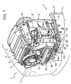
- Figure 1 is a perspective view showing the front part of a farm tractor equipped with a cooling system according to the present invention;
- Figure 2 is a schematic lateral view of a heat exchange assembly belonging to the cooling system of the tractor of Figure 1, in a corresponding operating position;
- Figure 3 is a partial, schematic perspective view of the heat exchange assembly of Figure 1, seen from its rear portion, in the aforesaid operating position;
- Figure 4 is a perspective view of the heat exchange assembly of Figure 1, in a corresponding first non-operating position;
- Figure 5 is a perspective view of the heat exchange assembly of Figure 1, in a corresponding second non-operating position.
- With reference to Figure 1, T indicates the front portion of a farm tractor, comprising a bonnet C housing the internal combustion engine of the tractor, not shown. The present invention relates specifically to a farm tractor, but obviously it may also be applied to other types of farm machines, such as for instance combine-harvesters and the like.
- The hood C is provided with grille-like openings, not shown, for inlet and outlet of a cooling air flow. A heat exchange assembly, globally referred to with number 1, is housed in the front portion of the bonnet C. The heat exchange assembly 1 comprises an
engine radiator 2, agearshift oil radiator 3, aradiator 4 of an intercooler system, and aradiator 5 belonging to an air conditioning unit of the tractor cabin; theradiator 5 is associated in quite a conventional way with arespective fan 6 and ade-hydrating filter 7. As can be seen in particular in Figure 2, the various radiators 2-5 of the assembly 1, globally prism-shaped, are arranged in sequence very close to one another, the larger surfaces of the various radiators being substantially parallel one to the other. - As shown in Figure 3, a ventilation assembly comprising a
conveyor 8 and asuction fan 9, actuated for instance by a belt, not shown, is mounted onto the rear portion of theheat exchange assembly 2. In quite a conventional way, thefan 9 generates an air flow referred to by arrows A in Figure 2, extending in a substantially orthogonal direction with respect to a front surface of the assembly 1, here represented by the front surface of theradiator 5. In the embodiment shown in the figures,number 10 refers to a lower support base, extending frontally from the lower portion of theconveyor 8 and fastened to afront support 11 of the tractor. - The
radiator 2 is mounted in a stationary position with respect to thebase 10 and to theconveyor 8, close to the latter. - The
radiator 4 comprises a frame having two lateral uprights, one of which referred to with 41, and alower cross-piece 42. Theradiator 4 with its frame is articulated so as to be shifted angularly. The means carrying out said articulation comprise two lateral arms extending longitudinally, one of which referred to with 43 in the figures; an end of eacharm 43 is coupled in a stationary way to a respective upright 41 and to theradiator 4, whereas the opposite end is coupled turnably to a respectivelateral wall 81 of theconveyor 8. Thelateral arms 43 are hollow inside and belong each to a duct for the fluid passing within theradiator 4; in particular, thearm 43, which can be seen only partially in Figure 5, belongs to an air intake branch coming from a turboblower, which air should be cooled within the radiator of the intercooler, whereas thearm 43 placed on the opposite side, and well visible in the figures, belongs to an air return branch for air cooled by the intercooler back to the engine. - To said purpose, each
arm 43 has respective openings, schematically referred to with 44 and 45 in Figure 2, defined on the side towards theradiator 4 and thewall 81 of theconveyor 81; the opening 44 communicates with a passage defined in the corresponding upright 41 and in the lateral wall of theradiator 4, suitable sealing means being placed in between, comprising for instance a seal referred to with 46 in Figure 1, or by direct welding onto theradiator 4; the opening 45 leans against the outer surface of thewall 81 of theconveyor 8, on a hole defined in saidwall 81, suitable sealing means being placed in between; on the outer surface of saidwall 81, on said hole, a sleeve or the end of a conveying tube for intercooler air is fastened; in Figure 3number 47 refers to the two aforesaid sleeves, fastened within thewall 81, which cooperate each with arespective arm 43. The turnable coupling between the end of thearm 43 on which the opening 45 resides and thewall 81 of theconveyor 8 can be achieved in any known way, provided that at least in the operating position of the assembly 1, as represented in Figures 1-3, thesleeves 47 are in fluid communication with the inner cavity of theirrespective arm 43, so as to enable the passage of air to be cooled by theradiator 4. As can be inferred, thearms 43 can be shifted angularly with respect to thewall 81, so as to rotate upwards around a horizontal axis substantially coaxial with theopenings 45. - Each upright 41 of the frame of the
radiator 4 is integral with acorresponding bracket 48, to which an end of agas spring 49 is fastened, the other end of said spring being articulated to the structure of theconveyor 8; the frame of theradiator 4 then has in the central area of itslower cross-piece 42 an engagement seat, referred to with 42A in Figure 4, for a movinghook 10A mounted onto thebase 10; saidseat 42A and thehook 10A belong to a known blocking/release device, here shown only schematically, for keeping theradiator 4 in its respective operating position. - In an advantageous embodiment of the invention, also the
radiator 3 is mounted so as to be shifted angularly. To said purpose, the frame of theradiator 3 comprises in its lower portion two lateral eyelets, only one of which is visible in the figures, where it is referred to with 31; the central hole of eacheyelet 31 is coaxial with the hole of a corresponding eyelet protruding from thebase 10; one of the two eyelets of thebase 10 is referred to with 32 in Figure 2; arespective pin 33 is fitted into the holes of theeyelets eyelets respective pins 33 form hinging means for theradiator 3, so as to enable its angular forward shift. - To the lateral wall of the frame of the radiator 3 a
bracket 34 having a longitudinally extending slot is fastened, into which bracket apin 34A integral with the corresponding lateral wall of the frame of the radiator is slidingly engaged, thebracket 34 and thepin 34A thus carrying out stroke-end means designed to limit the angular shift admitted for theradiator 3 with respect to theradiator 2. In a possible embodiment, thepin 34A can be shaped as a screw, so as to form together with the bracket 34 a blocking/release device for the radiator 3 (in practice, thescrew 34A being tightened, thebracket 34 keeps theradiator 3 against theradiator 2, whereas thescrew 34A partially loosened, the presence of the slot enables thebracket 34 to slide with respect to said screw). As an alternative, for instance on the side of the assembly 1 opposite the side with thebracket 34, between theradiators 2 and 3 a known hooking system can be mounted, designed to keep theradiator 3 close and parallel to theradiator 2. - In a particularly preferred embodiment of the invention, also the structure of the
radiator 5 can make angular forward shifts. In the case shown by way of example in the figures, theradiator 5 is thus associated with a frame having twolateral uprights 51 and alower cross-piece 52. The lower cross-piece is associated with twoeyelets 53, whose holes are coaxial with the holes ofcorresponding eyelets 54 frontally protruding from thecross-piece 42 of the frame of theradiator 4; arespective pin 55 is fitted into the holes of theeyelets eyelets respective pins 55 form hinging means for theradiator 5 with respect to theradiator 4, so as to enable its angular forward shift. - Here again means for keeping the
radiator 5 in its normal operating position, i.e. against theradiator 4, are envisaged. In the case shown by way of example, eacharm 43 has arespective end extension 43A, equipped with a threadedhole 43B (see Figure 5), into which the screw-shaped stem of ahand grip 43C is screwed. The free end of the stem of thehand grip 43C can be engaged or screwed into acorresponding seat 56 obtained on a respective lateral wall of the frame of theradiator 5. Obviously, as an alternative to the system disclosed by way of example, other known systems for blocking/releasing the structure of theradiator 5 with respect to the one of theradiator 4 can be envisaged. Here again stroke-end means limiting the angular forward shift of theradiator 5 can be envisaged; in the simplest embodiment, said means can consist of the flexible intake and return tubes for the fluid that has to pass within theradiator 5. - Finally, the assembly 1 is equipped with an electric cable for the
fan 6, not visible, and with flexible intake and return tubes for the fluids that have to pass within the radiators 2-5; some of these tubes can be seen in Figures 1-3. Note that in the operating position shown in Figures 1-3, the aforesaid cable and the various flexible tubes belonging to theradiators - The general working of the cooling system comprising the heat exchange assembly 1 is known per se, so that the following shall describe only the operations required to clean the radiators 2-5.
- In normal operating conditions of the tractor, the assembly 1 looks as can be seen in Figures 1-3, in which the various radiators 2-5 are leaning one against the other, substantially parallel to one another, and kept in position through their respective blocking/release means; the actuation of the
fan 9 causes the formation of the air flow A of Figure 2, which passes through the various radiators 2-5. When the assembly 1 has to be cleaned, the operator stops the tractor and lifts the bonnet C. - The blocking/release device comprising the
seat 42A and thehook 10A (Figure 1) is led to its release position and thanks to the actuation of thegas springs 49 the structure of theradiator 4 automatically shifts angularly upward together with theradiator 5, so as to reach the non-operating position visible in Figure 4; in this case, the stroke-end means limiting the angular shift of theradiator 4 are formed by said gas springs; the angular shift is enabled by the articulation system comprising thearms 43, which, as was mentioned, on one side are fastened to the frame of theradiator 4, and on the other side are turnably associated with the structure of theconveyor 8. As can be inferred, in said non-operating condition almost the whole front surface of theradiator 3 can be accessed directly by the operator, so as to carry out required cleaning operations. After that, also the aforesaid blocking/release device operating between theradiator 3 and the radiator 2 (which, as was said, can consist of thebracket 34 and of thescrew 34A) can be led to its respective release position; the operator can thus shift the radiator angularly forward, thanks to the presence of the hinging system comprising the pairs of eyelets 31-32 and theirrespective pins 33; the stroke-end means comprising thebracket 34 and the pin/screw 34A limit the angular movement of theradiator 3 and enable it to keep the non-operating position reached. Theradiator 3 thus lies in the position visible in Figure 4, in which almost the whole front surface of theradiator 2 can now be directly accessed by the operator, so as to carry out required cleaning operations. After cleaning theradiators radiator 4 can be lowered together with theradiator 5, and thus be led back to its original position, in which it is blocked by means of its respective hookingdevice radiator 5 angularly forward, thanks to the presence of the hooking system consisting of the pairs of eyelets 53-54 and of theirrespective pins 55, up to the position visible in Figure 5; as was said, it is provided for suitable stroke-end means, so as to limit the angular shift admitted for theradiator 5; in the non-operating position of theradiator 5, which can be seen in Figure 5, almost the whole front surface of theradiator 4 can now be accessed directly by the operator, so as to carry out required cleaning operations. Once said operations are ended, theradiator 5 can be led back to the position against theradiator 4, so as to be blocked again in position by means of the hand grips 43C. - From the above description it can be inferred that the system according to the invention enables to carry out effective and complete cleaning operations on the front surfaces of the various radiators provided for, easily and rapidly, with manifest advantages; the system described above ensures at the same time a compact structure for the heat exchange assembly and an optimal exploitation of the cooling air flow passing through the various radiators.
- Obviously, though the basic idea of the invention remains the same, construction details and embodiments can vary with respect to what has been described and shown by mere way of example, and the various functional components can be replaced by elements technically equivalent to those shown as examples.
- In the embodiment shown by way of example, the
arms 43 partially work as ducts for the intercooler radiator, and in said light their inner cavity and its end openings should have an appropriate section; it should further be pointed out that the arm articulation system could be used to shift angularly also a radiator differing from the one of the intercooler system.
Claims (21)
- Cooling system for a farm machine, comprising a heat exchange assembly (1) designed to receive a cooling air flow (A) in a direction substantially perpendicular to one of its end surfaces, said assembly (1) comprising a plurality of radiators (2, 3, 4, 5) arranged close one to the other and so as to be passed through by said air flow (A), wherein hinging means (43) are associated to at least a first radiator (4) of said plurality, designed to enable the angular shift of the first radiator (4) with respect to a second radiator (2, 3) of said plurality, between a respective operating position and a respective non-operating position, characterized in that the hinging means comprise at least an articulation arm (43) having an inner cavity which belongs to a passage duct for a fluid passing within the first radiator (4).
- System according to claim 1, characterized in that in said operating position the first radiator (4) is substantially parallel to the second radiator (2, 3), and in that in said non-operating position the first radiator (4) is inclined with respect to the second radiator (2, 3).
- System according to claim 1 or 2, characterized in that the hinging means (43) are designed to enable an angular upward shift of the first radiator (4) with respect to the second radiator (2, 3).
- System according to claim 1 or 2, characterized in that the articulation arm (43) is angularly movable around a respective rotation axis.
- System according to claim 4, characterized in that the arm (43) has a first area coupled in a stationary way with a lateral surface of the first radiator (4), and a second area coupled turnably with a support structure (81), said cavity having a first opening (44) on the first area, which is in fluid communication with the first radiator (4), and a second opening (45) on the second area, which is in fluid communication with a respective tube (47) of said fluid.
- System according to claim 1 or 5, characterized in that the hinging means comprise two of said articulation arms (43), an arm (43) belonging to an inlet duct of said fluid into the first radiator (4) and the other arm (43) belonging to an outlet duct of said fluid from the first radiator (4).
- System according to claim 1 or 2, characterized in that also the second radiator (3) is associated with respective hinging means (31-33; 53-55), designed to enable the angular shift of the second radiator (3) between a respective operating position and a respective non-operating position.
- System according to claim 7, characterized in that the second radiator (3) can be shifted angularly with respect to a further radiator (2) of said assembly (1), when the first radiator (4) is in its respective non-operating position.
- System according to claim 1 or 2, characterized in that said assembly (1) comprises at least a third radiator (5), to which respective hinging means (53-55) are associated, designed to enable the angular shift of the third radiator (5) between a respective operating position and a respective non-operating position.
- System according to claim 9, characterized in that the third radiator (5) can be angularly shifted with respect to the first radiator (4).
- System according to claim 10, characterized in that the third radiator (5) is articulated to the first radiator (4) by means of its respective hinging means (53-55).
- System according to one or more of the preceding claims, characterized in that a device (10A, 42A; 34, 34A; 43A, 43B, 43C, 56) is provided that can be switched between a blocking condition and a release condition, in its blocking condition said device (10A, 42A; 334, 34A; 43A, 43B, 43C, 56) keeping a respective radiator of said plurality (3, 4, 5) in its operating position, and in the release position said device (10A, 42A; 34, 34A; 43A, 43B, 43C, 56) enabling the shift of the respective radiator (3, 4, 5) to its non-operating position.
- System according to claim 12, characterized in that actuating means (48) is provided designed to shift automatically the first radiator (4) from its operating position to its non-operating position as a result of the switching of said device (10A, 42A; 34, 34A; 43A, 43B, 43C, 56) to its respective release condition, said actuating means comprising in particular at least a gas spring (49).
- System according to one or more of the preceding claims, characterized in that stopping means (34, 34A; 49) is provided, designed to limit the angular shift admitted for a respective radiator (3, 4, 5) of said plurality.
- System according to claims 7 or 9, characterized in that the hinging means (31-33; 53-55) associated to the second (3) and third (5) radiator are operatively coupled with the lower portion of a respective radiator (3, 5).
- System according to claim 1, characterized in that the first radiator (4) belongs to an intercooler system.
- System according to claim 1, characterized in that the second radiator is a radiator (2, 3) for cooling an oil or a motor.
- System according to claim 8, characterized in that the further radiator is a radiator for cooling an engine (2).
- System according to claim 9, characterized in that the third radiator (5) is a radiator of an air conditioning system.
- System according to claim 5, characterized in that said first area of the articulation arm (43) is coupled turnably with a respective wall (81) of a conveying element (8) in which operates a suction fan (9) inducing said air flow (A).
- Farm machine, in particular a tractor, comprising a cooling system carried out according to one or more of the preceding claims.
Applications Claiming Priority (2)
| Application Number | Priority Date | Filing Date | Title |
|---|---|---|---|
| IT000127A ITTO20030127A1 (en) | 2003-02-21 | 2003-02-21 | COOLING SYSTEM FOR AN AGRICULTURAL MACHINE. |
| ITTO20030127 | 2003-02-21 |
Publications (2)
| Publication Number | Publication Date |
|---|---|
| EP1450019A1 EP1450019A1 (en) | 2004-08-25 |
| EP1450019B1 true EP1450019B1 (en) | 2005-12-07 |
Family
ID=32732619
Family Applications (1)
| Application Number | Title | Priority Date | Filing Date |
|---|---|---|---|
| EP03026313A Expired - Lifetime EP1450019B1 (en) | 2003-02-21 | 2003-11-17 | Cooling system for a farm machine |
Country Status (4)
| Country | Link |
|---|---|
| US (1) | US7089994B2 (en) |
| EP (1) | EP1450019B1 (en) |
| DE (1) | DE60302647T2 (en) |
| IT (1) | ITTO20030127A1 (en) |
Families Citing this family (37)
| Publication number | Priority date | Publication date | Assignee | Title |
|---|---|---|---|---|
| JP4013636B2 (en) * | 2002-05-09 | 2007-11-28 | スズキ株式会社 | Motorcycle radiator device |
| US7353898B1 (en) * | 2005-02-24 | 2008-04-08 | Polaris Industries Inc. | Integrated heat exchanger and engine mount for a snowmobile |
| DE102005014614A1 (en) * | 2005-03-31 | 2006-10-05 | Deere & Company, Moline | cooler arrangement |
| US7455100B2 (en) * | 2005-06-28 | 2008-11-25 | Caterpillar Inc. | Cooling system having a pivotal heat exchanger |
| US7828097B2 (en) * | 2005-07-05 | 2010-11-09 | Yanmar Co., Ltd. | Construction machine |
| US20070095504A1 (en) * | 2005-10-24 | 2007-05-03 | Tuntland John E | Radiator for a work machine |
| DE102005051661A1 (en) * | 2005-10-28 | 2007-05-16 | Hbpo Gmbh | Support structure in the front area of a motor vehicle |
| GB0526621D0 (en) * | 2005-12-30 | 2006-02-08 | Agco Sa | Cooler installation |
| US7383905B2 (en) * | 2006-08-07 | 2008-06-10 | Deere & Company | Vehicle cooling system |
| US20090078394A1 (en) * | 2007-04-20 | 2009-03-26 | Leslie Roy Weatherup | Pivotal heat exchanger with remote opener |
| ES2306614B1 (en) * | 2007-04-23 | 2009-11-06 | Utiform Technologies, S.L. | REFRIGERATION SYSTEM FOR CONSTRUCTION MACHINES FOR CONSTRUCTION. |
| JPWO2009101935A1 (en) * | 2008-02-15 | 2011-06-09 | 日立建機株式会社 | Construction machinery |
| DE102008040908A1 (en) * | 2008-07-31 | 2010-02-11 | Deere & Company, Moline | Radiator arrangement for a vehicle cooling system |
| US20100301638A1 (en) * | 2009-05-29 | 2010-12-02 | Hinshaw Eric J | Integrated Air Intake System |
| US20100328885A1 (en) * | 2009-06-26 | 2010-12-30 | Scofield William H | Rotatable Cooling Module |
| GB0911287D0 (en) * | 2009-06-30 | 2009-08-12 | Agco Sa | Tractor cooling package |
| RU2532210C2 (en) | 2010-02-01 | 2014-10-27 | Поларис Индастриз Инк. | Vehicle cooling system |
| US8186751B2 (en) | 2010-05-06 | 2012-05-29 | Deere & Company | Pivotal fan/grill unit for a work vehicle |
| US20120103712A1 (en) * | 2010-11-03 | 2012-05-03 | Caterpillar Inc. | Skid steer machine having pivotably mounted cooling system and non-metallic vibration isolator |
| US8453777B2 (en) * | 2011-10-24 | 2013-06-04 | Deere & Company | Cooling fan duct assembly |
| EP2604460B1 (en) * | 2011-12-13 | 2016-04-13 | CNH Industrial Italia S.p.A. | Work vehicle having a cooling system with a reversible airflow |
| WO2013087106A1 (en) | 2011-12-15 | 2013-06-20 | Mettler-Toledo Ag | Reference electrode |
| US9435591B2 (en) * | 2012-09-10 | 2016-09-06 | Deere & Company | Heat exchanger pivotable for clean-out |
| US20140116658A1 (en) * | 2012-10-30 | 2014-05-01 | Deere & Company | Vehicle cooling system |
| US20140125070A1 (en) * | 2012-11-08 | 2014-05-08 | Caterpillar Sarl | Cooling package latch mechanism |
| US20140138066A1 (en) * | 2012-11-16 | 2014-05-22 | Caterpillar Sarl | Cooling package for a machine |
| US8936128B2 (en) * | 2013-02-22 | 2015-01-20 | Komatsu Ltd. | Engine room of a wheel loader |
| GB201312943D0 (en) | 2013-07-19 | 2013-09-04 | Agco Int Gmbh | Fan Shroud on an Agricultural Vehicle |
| DE102013217368A1 (en) * | 2013-08-30 | 2015-03-05 | Hamm Ag | Drive assembly, in particular for a construction machine, subassembly for a drive assembly and this comprehensive construction machine |
| US9090159B2 (en) * | 2013-11-15 | 2015-07-28 | Randall Industries, Inc. | Vibration dampened engine mounted radiator assembly |
| JP6415890B2 (en) | 2014-08-04 | 2018-10-31 | 株式会社クボタ | Work vehicle |
| JP6498017B2 (en) * | 2014-10-16 | 2019-04-10 | ヤンマー株式会社 | Work vehicle |
| JP6523824B2 (en) * | 2015-06-29 | 2019-06-05 | 三菱マヒンドラ農機株式会社 | Work vehicle |
| FR3042154B1 (en) * | 2015-10-09 | 2018-08-10 | Valeo Systemes Thermiques | FRONT FACE MODULE SUPPORT AND CORRESPONDING FRONT FACE MODULE |
| US10563925B2 (en) * | 2017-07-12 | 2020-02-18 | Caterpillar Inc. | Cooling assembly for service vehicle |
| JP7832018B2 (en) * | 2022-03-01 | 2026-03-17 | 日本車輌製造株式会社 | Carrier and cooling module for carrier |
| DE102024203242A1 (en) * | 2024-04-09 | 2025-10-09 | Volkswagen Aktiengesellschaft | Passenger car with heat exchanger module |
Family Cites Families (8)
| Publication number | Priority date | Publication date | Assignee | Title |
|---|---|---|---|---|
| US104491A (en) * | 1870-06-21 | Simeon a | ||
| US4696361A (en) * | 1984-03-23 | 1987-09-29 | Owatonna Manufacturing Company | Swing-up radiator and oil cooler assembly |
| DE4122512A1 (en) * | 1991-05-28 | 1992-12-03 | Kloeckner Humboldt Deutz Ag | COMPACT HEAT EXCHANGER FAN UNIT |
| JP3236764B2 (en) * | 1995-09-21 | 2001-12-10 | 新キャタピラー三菱株式会社 | Heat exchange equipment |
| US6092616A (en) * | 1998-06-05 | 2000-07-25 | Caterpillar S.A.R.L. | Cooling system for a skid steer loader |
| JP2000310119A (en) * | 1999-04-28 | 2000-11-07 | Shin Caterpillar Mitsubishi Ltd | Cooling system of working machine |
| ATE348252T1 (en) * | 1999-11-05 | 2007-01-15 | Cnh Oesterreich Gmbh | MOTOR VEHICLE WITH AN OIL COOLER |
| JP2001348909A (en) * | 2000-06-02 | 2001-12-21 | Shin Caterpillar Mitsubishi Ltd | Construction machinery |
-
2003
- 2003-02-21 IT IT000127A patent/ITTO20030127A1/en unknown
- 2003-11-17 DE DE60302647T patent/DE60302647T2/en not_active Expired - Lifetime
- 2003-11-17 EP EP03026313A patent/EP1450019B1/en not_active Expired - Lifetime
- 2003-11-25 US US10/720,223 patent/US7089994B2/en not_active Expired - Fee Related
Also Published As
| Publication number | Publication date |
|---|---|
| EP1450019A1 (en) | 2004-08-25 |
| US7089994B2 (en) | 2006-08-15 |
| US20040226683A1 (en) | 2004-11-18 |
| DE60302647T2 (en) | 2006-07-27 |
| ITTO20030127A1 (en) | 2004-08-22 |
| DE60302647D1 (en) | 2006-01-12 |
Similar Documents
| Publication | Publication Date | Title |
|---|---|---|
| US7089994B2 (en) | Cooling system for a farm machine | |
| AU570510B2 (en) | Mechanical cooling air cleaner | |
| US3837149A (en) | Engine enclosure and cooling system with rotary filter | |
| EP1903149B1 (en) | Construction machine | |
| US6248145B1 (en) | Cleaner for rotating air-intake filter | |
| ES2336353T3 (en) | INDOOR AIR CONDITIONER UNIT. | |
| US7997238B2 (en) | Engine and cooling system arrangement for a harvester | |
| EP2733342B1 (en) | Air filter arrangement for a work vehicle | |
| TR201617263T1 (en) | Air conditioner indoor unit. | |
| CA2550602C (en) | Rotating filter screen with baffle | |
| BR102016015702A2 (en) | system for directional airflow control in a harvester | |
| WO2014141792A1 (en) | Combine | |
| US20070175611A1 (en) | Integrated oil cooler and cleaning device | |
| JP2000310119A (en) | Cooling system of working machine | |
| KR20150102453A (en) | Combine | |
| KR102652751B1 (en) | Combine | |
| CN111852699A (en) | Engine air pre-cleaning system | |
| KR101158124B1 (en) | Air-conditioner | |
| KR101133612B1 (en) | Indoor unit of spilt type air conditioner | |
| EP1099837A1 (en) | Self-cleaning filtering device for the cooling system of an agricultural machine engine | |
| JP7083307B2 (en) | combine | |
| KR100575306B1 (en) | Indoor unit of air conditioner | |
| CN218243170U (en) | Protection device, generator and harvester | |
| CN111918546B (en) | Harvesters and work machines | |
| US4995306A (en) | Air circulating system for a person operating an engine powered piece of agricultural equipment |
Legal Events
| Date | Code | Title | Description |
|---|---|---|---|
| PUAI | Public reference made under article 153(3) epc to a published international application that has entered the european phase |
Free format text: ORIGINAL CODE: 0009012 |
|
| AK | Designated contracting states |
Kind code of ref document: A1 Designated state(s): AT BE BG CH CY CZ DE DK EE ES FI FR GB GR HU IE IT LI LU MC NL PT RO SE SI SK TR |
|
| AX | Request for extension of the european patent |
Extension state: AL LT LV MK |
|
| 17P | Request for examination filed |
Effective date: 20041006 |
|
| 17Q | First examination report despatched |
Effective date: 20041220 |
|
| GRAP | Despatch of communication of intention to grant a patent |
Free format text: ORIGINAL CODE: EPIDOSNIGR1 |
|
| AKX | Designation fees paid |
Designated state(s): DE FR GB IT |
|
| GRAS | Grant fee paid |
Free format text: ORIGINAL CODE: EPIDOSNIGR3 |
|
| GRAA | (expected) grant |
Free format text: ORIGINAL CODE: 0009210 |
|
| AK | Designated contracting states |
Kind code of ref document: B1 Designated state(s): DE FR GB IT |
|
| PG25 | Lapsed in a contracting state [announced via postgrant information from national office to epo] |
Ref country code: IT Free format text: LAPSE BECAUSE OF FAILURE TO SUBMIT A TRANSLATION OF THE DESCRIPTION OR TO PAY THE FEE WITHIN THE PRESCRIBED TIME-LIMIT;WARNING: LAPSES OF ITALIAN PATENTS WITH EFFECTIVE DATE BEFORE 2007 MAY HAVE OCCURRED AT ANY TIME BEFORE 2007. THE CORRECT EFFECTIVE DATE MAY BE DIFFERENT FROM THE ONE RECORDED. Effective date: 20051207 |
|
| REG | Reference to a national code |
Ref country code: GB Ref legal event code: FG4D |
|
| REF | Corresponds to: |
Ref document number: 60302647 Country of ref document: DE Date of ref document: 20060112 Kind code of ref document: P |
|
| ET | Fr: translation filed | ||
| PLBE | No opposition filed within time limit |
Free format text: ORIGINAL CODE: 0009261 |
|
| STAA | Information on the status of an ep patent application or granted ep patent |
Free format text: STATUS: NO OPPOSITION FILED WITHIN TIME LIMIT |
|
| 26N | No opposition filed |
Effective date: 20060908 |
|
| REG | Reference to a national code |
Ref country code: FR Ref legal event code: PLFP Year of fee payment: 13 |
|
| PGFP | Annual fee paid to national office [announced via postgrant information from national office to epo] |
Ref country code: IT Payment date: 20151119 Year of fee payment: 13 Ref country code: DE Payment date: 20151110 Year of fee payment: 13 Ref country code: GB Payment date: 20151111 Year of fee payment: 13 |
|
| PGFP | Annual fee paid to national office [announced via postgrant information from national office to epo] |
Ref country code: FR Payment date: 20151008 Year of fee payment: 13 |
|
| REG | Reference to a national code |
Ref country code: DE Ref legal event code: R119 Ref document number: 60302647 Country of ref document: DE |
|
| GBPC | Gb: european patent ceased through non-payment of renewal fee |
Effective date: 20161117 |
|
| REG | Reference to a national code |
Ref country code: FR Ref legal event code: ST Effective date: 20170731 |
|
| PG25 | Lapsed in a contracting state [announced via postgrant information from national office to epo] |
Ref country code: IT Free format text: LAPSE BECAUSE OF NON-PAYMENT OF DUE FEES Effective date: 20161117 Ref country code: FR Free format text: LAPSE BECAUSE OF NON-PAYMENT OF DUE FEES Effective date: 20161130 |
|
| PG25 | Lapsed in a contracting state [announced via postgrant information from national office to epo] |
Ref country code: GB Free format text: LAPSE BECAUSE OF NON-PAYMENT OF DUE FEES Effective date: 20161117 Ref country code: DE Free format text: LAPSE BECAUSE OF NON-PAYMENT OF DUE FEES Effective date: 20170601 |