Technical Field
The present invention relates generally to a
rocker arm structuring a valve train mechanism of an
internal combustion engine, and more particularly to
a technology scheming to improve operability and
durability, to prevent noises, and so on.
Background Art
In recent years, a valve train mechanism of an
internal combustion engine has often adopted a roller
type rocker arm including a roller rolling on a cam
lobe in order to restrain a loss of power and an
abrasion on a contact surface due to a friction with
a cam shaft. The roller type rocker arm has hitherto
adopted a cast or forged arm body, however, for
actualizing reductions in inertial mass of a valve
gear system and in manufacturing cost, as disclosed
in Japanese Patent Application Laid-Open Nos. 3-172506,
No. 7-150909 and so on, a variety of arm
bodies have been developed as steel plate press
formed products.
The arm body as the steel plate press formed
product is manufactured through processes of
obtaining a blank by punching out a steel plate, etc
in a predetermined contour, thereafter having this
blank subjected to plastic deformation by a press die
assembly, and forming the arm body constructed,
substantially in a U-shape in section, of a pair of
side walls and a connection wall connecting these
side walls. The arm body is formed with an aperture
through which the roller is exposed on the side of
the cam shaft, wherein this aperture is formed either
by a method of punching out after the press forming
of the arm body or by a method of punching out
simultaneously when punching the blank out. Note
that generally a boss, into which a pivot shaft is
screwed, is formed by a burring work when molding the
arm body, and through-holes, into and through which
the roller shaft is press-fitted and inserted, are
formed after having formed the arm body.
Incidentally, in the case of adopting the method
of punching out the arm body to form the aperture
after the press forming, it is inevitable that an
internal peripheral edge of the aperture protrudes
more or less as a stepped portion from internal
surfaces of the side walls in terms of a problem of a
way of setting dimensions of a punch for punching the
aperture out. As a result, during an operation of
the engine, the roller and a side end surface of a
bearing (normally a needle bearing) interferes with
the stepped portion of the internal peripheral edge
of the aperture. This interference hinders smooth
rotations of the roller and might be a factor of
causing an abnormal abrasion and an emission of
noises. On the other hand, when punched out, burrs
are produced on the side end surface of the aperture
of a roller holding member and, if bent towards an
interior of the arm body, might also interfere with
the roller and the side end surface of the bearing
thereof.
Disclosure of the Invention
The present invention, which was devised under
such circumstances, aims at providing a rocker arm
scheming to improve operability and durability and to
prevent noises, etc..
For solving the above problems, the present
invention provides a rocker arm comprising an arm
body, a shaft and a roller, wherein (1) the arm body,
(1a) formed substantially in the U-shape in section
by effecting drawing on a metal plate, includes (1b)
a pair of side walls, (1c) a connection wall
connecting the pair of side walls, (1d) an aperture
formed through the connection wall, and (1e) through-holes
at positions where the pair of side walls are
aligned with each other, (1f) a peripheral edge of
the aperture is so formed as to be finished by
inserting a first finishing die into the aperture
from between the pair of side walls, (2) the shaft is
fitted in the pair of through-holes and extended
between the pair of side walls, and (3) the roller is
rotatably supported on the shaft.
According to the present invention, for example,
a stepped portion between the internal surfaces of
the side walls and the internal peripheral edge of
the aperture is vanished by use of the finishing die
assembly having a width that is the same as or
slightly larger than a distance between the internal
surfaces of the two side walls.
Further, in the rocker arm according to the
present invention, it is preferable that external end
surfaces of the pair of side walls configuring a
rocker arm portion surrounding the aperture be so
formed as to be finished by pressing a second
finishing die against these surfaces.
According to this preferred mode of the present
invention, burrs produced on external end surfaces of
the side walls configuring the rocker arm portion
surrounding the aperture of the roller holding member,
are crushed by their being pressed by the second
finishing die and thus vanished.
Brief Description of the Drawings
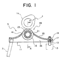
FIG. 1 is a vertical sectional view showing
principal portions of a valve train system according
to an embodiment of the present invention;
FIG. 2 is a sectional view taken along the line
A-A in FIG. 1;
FIG. 3 is a perspective view of an arm body;
FIG. 4 is a plan view of a blank;
FIG. 5 is a perspective view of a primary work;
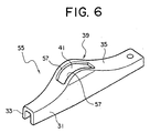
FIG. 6 is a perspective view of a secondary
work;
FIG. 7 is a view showing a process of
manufacturing a tertiary work;
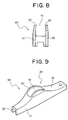
FIG. 8 is a vertical view of the tertiary work;
FIG. 9 is a perspective view of the tertiary
work; and
FIG. 10 is a view showing a process of
manufacturing a quaternary work.
Embodiments of the Invention
One embodiment in which the present invention is
applied to an external fulcrum type of rocker arm
used for an OHC (Overhead Camshaft) engine, will
hereinafter be described in conjunction with the
drawings. FIG. 1 is a vertical sectional view of
principal portions of a valve train system according
to the embodiment, and FIG. 2 is an enlarged
sectional view taken along the line A-A in FIG. 1.
As illustrated in these Figures, the valve train
system in the present embodiment is constructed of a
cam shaft 1 driven by an unillustrated crank shaft
through a timing belt, etc., a rocker arm 5 rocking
about a pivot bearing 3 as a fulcrum that is formed
in a cylinder head, and a valve 7 abutting on a free
end of the rocker arm 5 and thus driven vertically.
The rocker arm 5 includes, as its principal
constructive members, an arm body 11 as a press
formed product composed of a material such as a cold-rolled
steel, etc., a pivot shaft 13 screwed into one
end (proximal end) of the arm body 11, and a roller
15 disposed substantially at a central portion of the
arm body 11 and rolling on a cam lobe 1a of the cam
shaft 1. The pivot shaft 13 is, after screwed in a
boss 17 formed in the rocker arm 5, locked
unslackening by a lock nut 19. Further, the roller
15 is rotatably fitted on a roller pin 23 through a
needle bearing 21. The roller pin 23 is press-fitted
in the arm body 11
FIG. 3 is a perspective view of the arm body 11.
As shown in FIG. 3, the arm body 11 is constructed of
a pair of side walls 31, 33 and a connection wall 35
connecting these side walls 31, 33, whereby the arm
body 11 takes substantially a U-shape in section.
The arm body 11 is formed, substantially at its
central portion, with a roller holding portion 39
having through-holes 37 in which the roller pin 23 is
fitted, and the connection wall 35 of the roller
holding portion 39 is formed with a rectangular
aperture 41 through which an upper portion of the
roller 15 is exposed. Further, the proximal side end
of the arm body 11 is formed with a female thread 43
into which the pivot shaft 13 is screwed.
A process of manufacturing the arm body 11 will
hereinafter be described.
In the case of the present embodiment, a worker
at first punches a steel plate out by an
unillustrated punch, thereby obtaining a blank 51
shown in FIG. 4. Next, the worker effects drawing
(once or a plural number of times) by use of an
unillustrated drawing die assembly, thereby obtaining
a primary work 53 in which the roller holding member
39 protrudes upwards as FIG. 5 shows its perspective.
On this occasion, the boss 17 is formed by burring.
Next, the worker configures the aperture 41 by
punching out the connection wall 35 of the roller
holding portion 39 in the primary work 53 by using
the unillustrated punch, thereby obtaining a
secondary work 55 as FIG. 6 shows its perspective.
In the secondary work 55, inner peripheral edges 57
of the aperture 41 protrude in a flange-like shape
along the side walls 31, 33.
Subsequently, the worker, as shown in FIG. 7,
sets the secondary work 55 in an outer die 61 and has
a first finishing die 63 inserted from under. In the
case of the present embodiment, the first finishing
die 63 is formed slightly wider than an inside
interval between the two side walls 31, 33, or formed
in the same dimension as the inside interval between
the two side walls 31, 33. The inner peripheral
edges 57 of the aperture 41 are thereby bent up
(plastic working) or sheared, with the result that
the inner peripheral edges 57 become flush with
internal surfaces of the side walls 31, 33 in the
roller holding portion 39, and at the same time, the
internal surfaces of the side walls 31, 33 are
subjected to ironing to become smoother. A tertiary
work 65 shown in FIGS. 8 and 9 is thereby obtained.
Next, the worker, as shown in FIG. 10, presses a
secondary finishing die 71 against an upper surface
of the tertiary work 65, thus vanishing, by crushing,
minute burrs 73 generated when punching out for
forming the aperture 41. A quaternary work (not
shown) is thereby obtained. Note that the tertiary
work 65 be, it is desirable, set between the outer
die 61 and the first finishing die 63 (or within a
different type of jig) in order to prevent
deformations of the side walls 31, 33 on this
occasion.
Next, the worker performs working on the
quaternary work by the unillustrated punch and tap,
thereby completing the arm body 11 (FIG. 1) having
the through-holes 37 and the female thread 43.
In the present embodiment, the arm body 11 is
manufactured in the process described above, thereby
making it possible to obtain the smooth flat surfaces
with no stepped portion between the side walls 31, 33
and the inner peripheral edges 57 of the aperture 41
in the roller holding portion 39. As a result, the
rotations of the roller 15 are extremely smoothed by
reducing a frictional resistance, and at the same
time, even when used over a long period of time,
there are neither abrasions of the roller 15 and of
the end surface of the needle bearing 21 nor the
emission of noises caused by the rotations of the
roller 15.
The explanation of the specific embodiment comes
to an end so far, however, the mode of the present
invention is not limited to this embodiment. For
example, in the embodiment discussed above, the
present invention is applied to the external fulcrum
type of rocker arm and can be also applied to an
internal fulcrum type of rocker arm. Further, in a
valve train system where a rush adjuster is adopted
for the pivot, the adjusting type of pivot shaft is
not required, and hence the pivot protrusion can be
integrally formed on the proximal end of the arm body.
For others, the specific construction of the valve
train mechanism inclusive of the specific
configuration of the arm body and the manufacturing
process thereof, can be properly changed within the
range that does not deviate from the gist of the
present invention.
As discussed above, according to the present
invention, the rocker arm comprises the arm body, the
shaft and the roller. The arm body is formed
substantially in the U-shape in section by effecting
the drawing on the metal plate, and includes the
connection wall connecting the pair of side walls,
the aperture formed through the connection wall, and
the through-holes at positions where the pair of side
walls are aligned with each other. The peripheral
edge of the aperture is so formed as to be finished
by inserting the first finishing die into the
aperture from between the pair of side walls. The
shaft is fitted in the pair of through-holes and
extended between the pair of side walls. The roller
is rotatably supported on the shaft. Hence the
stepped portion between the internal surfaces of the
side walls and the inner peripheral edge of the
aperture are vanished, with the result that the
rotations of the roller are smoothed and, at the same
time, even when used over a long period of time,
there are neither abrasions of the roller and of the
end surface of the needle bearing nor the emission of
noises caused by the rotations of the roller.
Moreover, according to the preferred mode of the
present invention, in the rocker arm of the present
invention, the external end surfaces of the pair of
side walls configuring the rocker arm portion
surrounding the aperture are so formed as to be
finished by pressing the second finishing die against
these surfaces. Therefore, the burrs produced on the
external end surfaces of the side walls configuring
the rocker arm portion surrounding the aperture of
the roller holding member, are crushed by their being
pressed by the second finishing die and thus vanished,
thereby causing no interference with the roller and
with the side end surfaces of the bearing, which
might be derived from flexures of the burrs inwards
of the arm body.