EP1449802A1 - Combination elevator doors - Google Patents
Combination elevator doors Download PDFInfo
- Publication number
- EP1449802A1 EP1449802A1 EP04002978A EP04002978A EP1449802A1 EP 1449802 A1 EP1449802 A1 EP 1449802A1 EP 04002978 A EP04002978 A EP 04002978A EP 04002978 A EP04002978 A EP 04002978A EP 1449802 A1 EP1449802 A1 EP 1449802A1
- Authority
- EP
- European Patent Office
- Prior art keywords
- door
- car
- hoistway
- landing
- panels
- Prior art date
- Legal status (The legal status is an assumption and is not a legal conclusion. Google has not performed a legal analysis and makes no representation as to the accuracy of the status listed.)
- Granted
Links
- 238000009434 installation Methods 0.000 abstract description 9
- 230000009286 beneficial effect Effects 0.000 description 2
- 230000000694 effects Effects 0.000 description 1
- 238000010348 incorporation Methods 0.000 description 1
- 238000000034 method Methods 0.000 description 1
- 238000005549 size reduction Methods 0.000 description 1
Images


Classifications
-
- B—PERFORMING OPERATIONS; TRANSPORTING
- B66—HOISTING; LIFTING; HAULING
- B66B—ELEVATORS; ESCALATORS OR MOVING WALKWAYS
- B66B13/00—Doors, gates, or other apparatus controlling access to, or exit from, cages or lift well landings
- B66B13/30—Constructional features of doors or gates
-
- B—PERFORMING OPERATIONS; TRANSPORTING
- B66—HOISTING; LIFTING; HAULING
- B66B—ELEVATORS; ESCALATORS OR MOVING WALKWAYS
- B66B13/00—Doors, gates, or other apparatus controlling access to, or exit from, cages or lift well landings
- B66B13/02—Door or gate operation
- B66B13/06—Door or gate operation of sliding doors
-
- B—PERFORMING OPERATIONS; TRANSPORTING
- B66—HOISTING; LIFTING; HAULING
- B66B—ELEVATORS; ESCALATORS OR MOVING WALKWAYS
- B66B19/00—Mining-hoist operation
- B66B19/007—Mining-hoist operation method for modernisation of elevators
Definitions
- the present invention relates to sliding doors used on cars and landings of elevator systems.
- the invention provides door arrangements that permit greater versatility of space utilization within a hoistway of an elevator system.
- EP 1069066 describes an elevator installation with landing doors, and in some instances car doors, that can be laterally displaced beyond the width of the hoistway into recesses provided in opposing hoistway walls or alternatively into recesses provided in a new front module for the entrance to the hoistway. Accordingly, the hoistway is not dimensioned to fully accommodate the door-receiving spaces. Whereas this technique is beneficial in designing new installations, it will be appreciated that it is not appropriate for modernizing existing installations since it requires extensive building work, either to cut out the required recesses in the hoistway walls or to install a new front module at each landing.
- the principal objective of the present invention is to overcome the shortcomings of the prior art by providing combination elevator door arrangements which permit more flexibility for the utilization of space within hoistways of elevator systems. Furthermore, the invention should be equally suitable for the modernization of existing elevator systems as well as for the design of new installations.
- the invention does not require purpose-built recesses in the hoistway walls or new front modules at each landing to accommodate landing doors that extend beyond the width of the hoistway. Accordingly, it can be applied to an existing elevator system without entailing excessive building work.
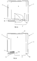
- Fig. 1 illustrates an elevator system 1 mounted within a building.
- the system 1 includes an elevator car 4 which is movable vertically within a hoistway 2 to transfer people between floors of the building.
- the hoistway 2 is defined by two opposing side walls 14, a rear wall 15 and a front wall 16.
- On each floor of the building an entrance 3 is provided to the hoistway 2 through the front wall 16.
- a horizontally sliding landing door 5 is mounted on each entrance 3 to the hoistway 2.
- the landing door 5 is composed of two vertically aligned panels 6.
- a two-panel 8 horizontally sliding door 7 is mounted on the car 4.
- the car door 7 interlocks with the neighboring landing door 5 and both slide telescopically into respective door-receiving spaces A and B within the hoistway 2 to one side of the entrance 3 as shown in Fig. 2.
- the panels 6 and 8 of the car and landing doors are arranged one behind the other.
- the telescopic landing door 6 is formed using the same number of panels as the car door 8. Accordingly, the receiving space B required to store the landing door 6 is substantially equal to the receiving space A for the car door 10.
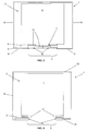
- Figs. 3 and 4 show an elevator system 1 incorporating a telescopic, side-opening door arrangement according to the present invention.
- the landing door 10 comprises two panels 11 and the car door 12 comprises three panels 13.
- Figs. 5 and 6 show an elevator system 1 incorporating a center-opening door arrangement according to a second embodiment of the invention.
- Two non-telescopic landing doors 10 are provided to close the entrance 3 and two telescopic doors 12 are mounted on the car 4. Both sets of doors 10 and 12 open from and close to the center of the entrance 3.
- the door-receiving space A for each of the car doors 7 does not extend outwards from the side of the car 4 into the hoistway 3. Accordingly, it is believed that this door arrangement would be particularly suitable for incorporation into a panoramic installation.
- Fig. 7 shows a side-opening door arrangement which is similar to that of Fig. 4 but with two panels 13 forming the telescopic car door 12 and three panels 11 forming the telescopic landing door 10.
- the reclaimed space C in this instance could be used for hoistway cabling, a control box or, if applied to a hydraulic elevator system, a jack.
Landscapes
- Elevator Door Apparatuses (AREA)
Abstract
Description
- The present invention relates to sliding doors used on cars and landings of elevator systems. In particular the invention provides door arrangements that permit greater versatility of space utilization within a hoistway of an elevator system.
- Telescopic, sliding doors have been widely used in many diverse applications for a great number of years. A common application employed within the elevator industry is as exemplified in US 3,389,504 which shows a two panel side-opening door installed on a car movable within a hoistway together with a similar two panel side-opening door mounted across an entrance on a neighboring landing of the hoistway. Both doors interlock and telescopically slide into respective door-receiving spaces to the side of the entrance to permit access to the car. Obviously, the room taken up by the door-receiving spaces in the hoistway cannot be used for any other purpose.
- Hitherto installation designers, who are under continual pressure to reduce the space consumption of modern elevator systems, were restricted by this requirement and have had no scope to utilize the door-receiving spaces required by the conventional car and landing door arrangement.
- This problem was partially addressed by EP 1069066 which describes an elevator installation with landing doors, and in some instances car doors, that can be laterally displaced beyond the width of the hoistway into recesses provided in opposing hoistway walls or alternatively into recesses provided in a new front module for the entrance to the hoistway. Accordingly, the hoistway is not dimensioned to fully accommodate the door-receiving spaces. Whereas this technique is beneficial in designing new installations, it will be appreciated that it is not appropriate for modernizing existing installations since it requires extensive building work, either to cut out the required recesses in the hoistway walls or to install a new front module at each landing.
- The principal objective of the present invention is to overcome the shortcomings of the prior art by providing combination elevator door arrangements which permit more flexibility for the utilization of space within hoistways of elevator systems. Furthermore, the invention should be equally suitable for the modernization of existing elevator systems as well as for the design of new installations.
- These objectives are achieved by the invention as defined in t he appended claims. In particular, the invention does not require purpose-built recesses in the hoistway walls or new front modules at each landing to accommodate landing doors that extend beyond the width of the hoistway. Accordingly, it can be applied to an existing elevator system without entailing excessive building work.
- By way of example only, preferred embodiments of the present invention will be described in detail with reference to the accompanying drawings, of which:
- FIG. 1 is a sectional plan view of an elevator system employing a conventional telescopic door arrangement;
- FIG. 2 shows the telescopic door arrangement of Fig. 1 in an open position;
- FIG. 3 is a sectional plan view of an elevator system employing a telescopic door arrangement according a first embodiment of the present invention;
- FIG. 4 shows the telescopic door arrangement of Fig. 1 in an open position;
- FIG. 5 is a sectional plan view of an elevator system employing a door arrangement according a second embodiment of the present invention;
- FIG. 6 shows the door arrangement of Fig. 6 in the open condition; and
- FIG. 7 is a sectional plan view of an elevator system employing a telescopic door arrangement according a third embodiment of the present invention.
-
- Fig. 1 illustrates an
elevator system 1 mounted within a building. Thesystem 1 includes anelevator car 4 which is movable vertically within ahoistway 2 to transfer people between floors of the building. Thehoistway 2 is defined by twoopposing side walls 14, arear wall 15 and afront wall 16. On each floor of the building anentrance 3 is provided to thehoistway 2 through thefront wall 16. For safety reasons a horizontally slidinglanding door 5 is mounted on eachentrance 3 to thehoistway 2. Thelanding door 5 is composed of two vertically alignedpanels 6. Similarly, a two-panel 8 horizontally slidingdoor 7 is mounted on thecar 4. - In use, when the
elevator car 4 reaches a designated floor, thecar door 7 interlocks with the neighboringlanding door 5 and both slide telescopically into respective door-receiving spaces A and B within thehoistway 2 to one side of theentrance 3 as shown in Fig. 2. In the stored positions, thepanels - In this arrangement the
telescopic landing door 6 is formed using the same number of panels as thecar door 8. Accordingly, the receiving space B required to store thelanding door 6 is substantially equal to the receiving space A for thecar door 10. - Figs. 3 and 4 show an
elevator system 1 incorporating a telescopic, side-opening door arrangement according to the present invention. In contrast to the prior art, thelanding door 10 comprises twopanels 11 and thecar door 12 comprises threepanels 13. With this arrangement, there is a reduction in the width of the receiving space A required for thecar door 10 when in the open position (Fig. 4) as compared to the prior art and accordingly a reclaimed space C within thehoistway 2 can be used for other purposes. - Although this solution would necessarily increase the depth of the car door receiving space A, and thereby result in a reduction in the
car 4 size for a givenhoistway 2, it gives the installation designer the flexibility to use the reclaimed space C in thehoistway 2 for other equipment such as an elongated counterweight. Indeed, if the counterweight is elongated, its width can be reduced correspondingly, thereby permitting thecar 4 to be widened to negate the size reduction effects imposed upon it by the increased depth of the car door-receiving space A. - It is perceived that the door arrangement of Figs. 3 and 4 would be particularly beneficial in a panoramic elevator system wherein the
walls hoistway 2 andcar 4 are substantially transparent. Understandably aesthetics is an extremely important factor in such an installation. With the prior art door arrangement of Figs. 1 and 2, thecar door 7 must be guided along unsightly supports extending from the side of the car into thehoistway 2. With the door arrangement of Figs. 3 and 4 the length of the supports can be reduced and therefor the overall appearance of the system is improved. - Figs. 5 and 6 show an
elevator system 1 incorporating a center-opening door arrangement according to a second embodiment of the invention. Twonon-telescopic landing doors 10 are provided to close theentrance 3 and twotelescopic doors 12 are mounted on thecar 4. Both sets ofdoors entrance 3. I n this particular embodiment, it will be noticed that the door-receiving space A for each of thecar doors 7 does not extend outwards from the side of thecar 4 into thehoistway 3. Accordingly, it is believed that this door arrangement would be particularly suitable for incorporation into a panoramic installation. - Fig. 7 shows a side-opening door arrangement which is similar to that of Fig. 4 but with two
panels 13 forming thetelescopic car door 12 and threepanels 11 forming thetelescopic landing door 10. The reclaimed space C in this instance could be used for hoistway cabling, a control box or, if applied to a hydraulic elevator system, a jack. - Although all of the embodiments specifically illustrated incorporate
rectangular hoistways 2 andcars 4, it will be appreciated that the invention is equally applicable to cylindrical hoistways and cars having arcuate sliding doors. - Furthermore, it is envisaged that the invention is equally applicable to hydraulically, pneumatically or mechanically driven elevator systems.
Claims (6)
- An elevator system (1) comprising:wherein, the landing door (10) and the car door (12) are each formed from one or more panels (11;13);a hoistway (2) accessible through at least one entrance (3) provided with at least one sliding landing door (10);a car (4) mounted and moveable within the hoistway (2), the car (4) having at least one sliding car door (12);
the number of panels (11) in the landing door (10) is unequal to the number of panels (13) in the car door (12); and
in use, the car door (12) opens together with a neighboring landing door (10)
CHARACTERISED IN THAT
in an open position, both the car door (12) and the neighboring landing door (10) are fully accommodated within the hoistway (2) and a space (C) is defined between the car door (12), the landing door (10) and a side wall (15) of the hoistway (2). - An elevator system (1) according to claim 1, wherein the car door (12) has a plurality of panels (13) and the landing door (10) has fewer panels (11) such that when opening, the car panels (13) telescope over each other into a car door-receiving space (A) in the hoistway (2) to a side of the entrance (3) and the neighboring landing door (10) slides into a landing door-receiving space (B) in the hoistway (2) to a side of the entrance (3), and consequentially the car door-receiving space (A) is not as wide as the landing door-receiving space (B).
- An elevator system (1) according to claim 2, wherein the landing door (10) is formed from a single panel (11).
- An elevator system (1) according to claim 1, wherein the landing door (10) has a plurality of panels (13) and the car door (12) has fewer panels (11 ) such that when opening, the car door (12) slides into a car door-receiving space (A) in the hoistway (2) to a side of the entrance (3) and the panels (11) of neighboring landing door (10) telescope over each other into a landing door-receiving space (B) in the hoistway (2) to a side of the entrance (3), and consequentially the car door-receiving space (A) is wider than the landing door-receiving space (B).
- An elevator system (1) according to claim 4, wherein the car door (12) is formed from a single panel (13).
- An elevator system (1) according to any preceding claim, wherein each entrance (3) has two sliding landing doors (10) and the car (4) has two sliding car doors (12), the car doors (12) and the neighboring landing doors (10) opening from and closing to a center of the entrance (3).
Priority Applications (1)
| Application Number | Priority Date | Filing Date | Title |
|---|---|---|---|
| EP20040002978 EP1449802B1 (en) | 2003-02-24 | 2004-02-11 | Combination elevator doors |
Applications Claiming Priority (3)
| Application Number | Priority Date | Filing Date | Title |
|---|---|---|---|
| EP03405118 | 2003-02-24 | ||
| EP03405118 | 2003-02-24 | ||
| EP20040002978 EP1449802B1 (en) | 2003-02-24 | 2004-02-11 | Combination elevator doors |
Publications (2)
| Publication Number | Publication Date |
|---|---|
| EP1449802A1 true EP1449802A1 (en) | 2004-08-25 |
| EP1449802B1 EP1449802B1 (en) | 2007-10-24 |
Family
ID=32737427
Family Applications (1)
| Application Number | Title | Priority Date | Filing Date |
|---|---|---|---|
| EP20040002978 Expired - Lifetime EP1449802B1 (en) | 2003-02-24 | 2004-02-11 | Combination elevator doors |
Country Status (1)
| Country | Link |
|---|---|
| EP (1) | EP1449802B1 (en) |
Cited By (4)
| Publication number | Priority date | Publication date | Assignee | Title |
|---|---|---|---|---|
| WO2007012913A1 (en) * | 2005-07-28 | 2007-02-01 | Otis Elevator Company | Elevator door with a set of landing doors and car doors with reduced thickness as a replacement for existing doors |
| EP1878685A1 (en) * | 2006-07-10 | 2008-01-16 | Wittur Holding GmbH | Door construction for a lift |
| EP1878686A1 (en) * | 2006-07-10 | 2008-01-16 | Wittur Holding GmbH | Door construction for a lift |
| EP2199246A1 (en) | 2008-12-19 | 2010-06-23 | Orona, S. Coop. | Door for accesses of elevator apparatuses, elevator apparatus and method for operating said door |
Citations (3)
| Publication number | Priority date | Publication date | Assignee | Title |
|---|---|---|---|---|
| US5584365A (en) * | 1994-09-16 | 1996-12-17 | Otis Elevator Company | Telescoping elevator door system |
| EP1069066A1 (en) * | 1999-07-12 | 2001-01-17 | Inventio Ag | Landing doors for a lift unit |
| US6336523B1 (en) * | 1998-09-08 | 2002-01-08 | Kabushiki Kaisha Toshiba | Elevator having an auxiliary control device mounted in the elevator shaft in the vicinity of a door pocket |
-
2004
- 2004-02-11 EP EP20040002978 patent/EP1449802B1/en not_active Expired - Lifetime
Patent Citations (3)
| Publication number | Priority date | Publication date | Assignee | Title |
|---|---|---|---|---|
| US5584365A (en) * | 1994-09-16 | 1996-12-17 | Otis Elevator Company | Telescoping elevator door system |
| US6336523B1 (en) * | 1998-09-08 | 2002-01-08 | Kabushiki Kaisha Toshiba | Elevator having an auxiliary control device mounted in the elevator shaft in the vicinity of a door pocket |
| EP1069066A1 (en) * | 1999-07-12 | 2001-01-17 | Inventio Ag | Landing doors for a lift unit |
Cited By (5)
| Publication number | Priority date | Publication date | Assignee | Title |
|---|---|---|---|---|
| WO2007012913A1 (en) * | 2005-07-28 | 2007-02-01 | Otis Elevator Company | Elevator door with a set of landing doors and car doors with reduced thickness as a replacement for existing doors |
| EP1878685A1 (en) * | 2006-07-10 | 2008-01-16 | Wittur Holding GmbH | Door construction for a lift |
| EP1878686A1 (en) * | 2006-07-10 | 2008-01-16 | Wittur Holding GmbH | Door construction for a lift |
| CN101104496B (en) * | 2006-07-10 | 2011-01-26 | 维托控股有限公司 | Door construction for a lift |
| EP2199246A1 (en) | 2008-12-19 | 2010-06-23 | Orona, S. Coop. | Door for accesses of elevator apparatuses, elevator apparatus and method for operating said door |
Also Published As
| Publication number | Publication date |
|---|---|
| EP1449802B1 (en) | 2007-10-24 |
Similar Documents
| Publication | Publication Date | Title |
|---|---|---|
| EP2665670B1 (en) | System having multiple cabs in an elevator shaft | |
| EP2376359B1 (en) | Elevator door frame with electronics housing | |
| DE69927565T2 (en) | Arrangement of the control system | |
| US10392225B2 (en) | Suspension and lift motor systems for a plurality of elevator cabs and counterweights that move independently of each other in different sections of a hoistway | |
| EP1449802B1 (en) | Combination elevator doors | |
| EP3517478B1 (en) | Elevator component access cabinet | |
| EP1704993B1 (en) | Structural board comprising an illuminator | |
| EP1377516B1 (en) | Hydraulic drive unit mounted in the elevator shaft | |
| WO2005056458A1 (en) | Assistant ceiling device for shielding escape hatch of elevator | |
| CN201161856Y (en) | Elevator with a movable elevator car | |
| JP3430106B2 (en) | Elevator equipment | |
| CN105883560A (en) | Elevator door arrangement | |
| CN101209794A (en) | Elevator without engine room device | |
| JP2007326684A (en) | Elevator equipment | |
| WO2011159300A1 (en) | Elevator door assembly including a low friction material slider layer | |
| FI115900B (en) | Shaft door to a lift | |
| JP2001247283A (en) | Door for elevator | |
| JP6270632B2 (en) | Elevator balance weight device for observation | |
| AU2015201264C1 (en) | System having multiple cabs in an elevator shaft | |
| JPH10324475A (en) | Elevator equipment | |
| KR20050027806A (en) | Variable jamb apparatus of elevator | |
| JP2830728B2 (en) | Operation panel for elevator | |
| JPS62285886A (en) | Elevator device | |
| JPH04129986A (en) | Lift path and arrangement structure for circulative elevator | |
| CN106276493A (en) | A kind of machine-roomless lift |
Legal Events
| Date | Code | Title | Description |
|---|---|---|---|
| PUAI | Public reference made under article 153(3) epc to a published international application that has entered the european phase |
Free format text: ORIGINAL CODE: 0009012 |
|
| AK | Designated contracting states |
Kind code of ref document: A1 Designated state(s): AT BE BG CH CY CZ DE DK EE ES FI FR GB GR HU IE IT LI LU MC NL PT RO SE SI SK TR |
|
| AX | Request for extension of the european patent |
Extension state: AL LT LV MK |
|
| 17P | Request for examination filed |
Effective date: 20050207 |
|
| AKX | Designation fees paid |
Designated state(s): AT CH DE FR GB LI |
|
| RBV | Designated contracting states (corrected) |
Designated state(s): AT CH DE FR GB LI |
|
| 17Q | First examination report despatched |
Effective date: 20060622 |
|
| GRAP | Despatch of communication of intention to grant a patent |
Free format text: ORIGINAL CODE: EPIDOSNIGR1 |
|
| GRAS | Grant fee paid |
Free format text: ORIGINAL CODE: EPIDOSNIGR3 |
|
| GRAA | (expected) grant |
Free format text: ORIGINAL CODE: 0009210 |
|
| AK | Designated contracting states |
Kind code of ref document: B1 Designated state(s): AT CH DE FR GB LI |
|
| REG | Reference to a national code |
Ref country code: GB Ref legal event code: FG4D |
|
| REG | Reference to a national code |
Ref country code: CH Ref legal event code: EP |
|
| REF | Corresponds to: |
Ref document number: 602004009624 Country of ref document: DE Date of ref document: 20071206 Kind code of ref document: P |
|
| ET | Fr: translation filed | ||
| PGFP | Annual fee paid to national office [announced via postgrant information from national office to epo] |
Ref country code: CH Payment date: 20080516 Year of fee payment: 5 |
|
| PLBI | Opposition filed |
Free format text: ORIGINAL CODE: 0009260 |
|
| PLAX | Notice of opposition and request to file observation + time limit sent |
Free format text: ORIGINAL CODE: EPIDOSNOBS2 |
|
| 26 | Opposition filed |
Opponent name: OTIS ELEVATOR COMPANY Effective date: 20080723 |
|
| PLAF | Information modified related to communication of a notice of opposition and request to file observations + time limit |
Free format text: ORIGINAL CODE: EPIDOSCOBS2 |
|
| PLBB | Reply of patent proprietor to notice(s) of opposition received |
Free format text: ORIGINAL CODE: EPIDOSNOBS3 |
|
| PGFP | Annual fee paid to national office [announced via postgrant information from national office to epo] |
Ref country code: AT Payment date: 20090218 Year of fee payment: 6 |
|
| PGFP | Annual fee paid to national office [announced via postgrant information from national office to epo] |
Ref country code: DE Payment date: 20090219 Year of fee payment: 6 |
|
| PGFP | Annual fee paid to national office [announced via postgrant information from national office to epo] |
Ref country code: GB Payment date: 20090219 Year of fee payment: 6 |
|
| REG | Reference to a national code |
Ref country code: CH Ref legal event code: PL |
|
| PG25 | Lapsed in a contracting state [announced via postgrant information from national office to epo] |
Ref country code: LI Free format text: LAPSE BECAUSE OF NON-PAYMENT OF DUE FEES Effective date: 20090228 Ref country code: CH Free format text: LAPSE BECAUSE OF NON-PAYMENT OF DUE FEES Effective date: 20090228 |
|
| PGFP | Annual fee paid to national office [announced via postgrant information from national office to epo] |
Ref country code: FR Payment date: 20090213 Year of fee payment: 6 |
|
| GBPC | Gb: european patent ceased through non-payment of renewal fee |
Effective date: 20100211 |
|
| REG | Reference to a national code |
Ref country code: FR Ref legal event code: ST Effective date: 20101029 |
|
| PLAY | Examination report in opposition despatched + time limit |
Free format text: ORIGINAL CODE: EPIDOSNORE2 |
|
| PG25 | Lapsed in a contracting state [announced via postgrant information from national office to epo] |
Ref country code: AT Free format text: LAPSE BECAUSE OF NON-PAYMENT OF DUE FEES Effective date: 20100211 |
|
| PG25 | Lapsed in a contracting state [announced via postgrant information from national office to epo] |
Ref country code: FR Free format text: LAPSE BECAUSE OF NON-PAYMENT OF DUE FEES Effective date: 20100301 |
|
| PG25 | Lapsed in a contracting state [announced via postgrant information from national office to epo] |
Ref country code: DE Free format text: LAPSE BECAUSE OF NON-PAYMENT OF DUE FEES Effective date: 20100901 |
|
| PG25 | Lapsed in a contracting state [announced via postgrant information from national office to epo] |
Ref country code: GB Free format text: LAPSE BECAUSE OF NON-PAYMENT OF DUE FEES Effective date: 20100211 |
|
| PLBC | Reply to examination report in opposition received |
Free format text: ORIGINAL CODE: EPIDOSNORE3 |
|
| PLBD | Termination of opposition procedure: decision despatched |
Free format text: ORIGINAL CODE: EPIDOSNOPC1 |
|
| PLBM | Termination of opposition procedure: date of legal effect published |
Free format text: ORIGINAL CODE: 0009276 |
|
| STAA | Information on the status of an ep patent application or granted ep patent |
Free format text: STATUS: OPPOSITION PROCEDURE CLOSED |
|
| 27C | Opposition proceedings terminated |
Effective date: 20111222 |