EP1449800A1 - Emergency stopper of elevator - Google Patents
Emergency stopper of elevator Download PDFInfo
- Publication number
- EP1449800A1 EP1449800A1 EP01274836A EP01274836A EP1449800A1 EP 1449800 A1 EP1449800 A1 EP 1449800A1 EP 01274836 A EP01274836 A EP 01274836A EP 01274836 A EP01274836 A EP 01274836A EP 1449800 A1 EP1449800 A1 EP 1449800A1
- Authority
- EP
- European Patent Office
- Prior art keywords
- elevator car
- roller
- guide rail
- elevator
- speed
- Prior art date
- Legal status (The legal status is an assumption and is not a legal conclusion. Google has not performed a legal analysis and makes no representation as to the accuracy of the status listed.)
- Granted
Links
Images


Classifications
-
- B—PERFORMING OPERATIONS; TRANSPORTING
- B66—HOISTING; LIFTING; HAULING
- B66B—ELEVATORS; ESCALATORS OR MOVING WALKWAYS
- B66B5/00—Applications of checking, fault-correcting, or safety devices in elevators
- B66B5/02—Applications of checking, fault-correcting, or safety devices in elevators responsive to abnormal operating conditions
- B66B5/16—Braking or catch devices operating between cars, cages, or skips and fixed guide elements or surfaces in hoistway or well
-
- B—PERFORMING OPERATIONS; TRANSPORTING
- B66—HOISTING; LIFTING; HAULING
- B66B—ELEVATORS; ESCALATORS OR MOVING WALKWAYS
- B66B5/00—Applications of checking, fault-correcting, or safety devices in elevators
- B66B5/02—Applications of checking, fault-correcting, or safety devices in elevators responsive to abnormal operating conditions
- B66B5/16—Braking or catch devices operating between cars, cages, or skips and fixed guide elements or surfaces in hoistway or well
- B66B5/18—Braking or catch devices operating between cars, cages, or skips and fixed guide elements or surfaces in hoistway or well and applying frictional retarding forces
- B66B5/20—Braking or catch devices operating between cars, cages, or skips and fixed guide elements or surfaces in hoistway or well and applying frictional retarding forces by means of rotatable eccentrically-mounted members
Definitions
- This invention relates to an emergency elevator stopping apparatus (elevator safety device) capable of stopping an elevator car easily when a speed thereof increases even while the elevator car moves up, and having an excellent durability.
- JP-B-52-18973 The emergency elevator stopping apparatus disclosed in JP-B-52-18973 is known as an example of a related art general emergency elevator stopping apparatus. This related art example will now be described.
- a related art emergency elevator stopping apparatus 20 is fixed to a lower portion of an elevator car guided along a guide rail 21 provided in an elevator shaft.
- a speed of the elevator car is detected by a governor via a governor rope 22 provided in the elevator shaft, and the speed data are transmitted to an emergency stopper 23 joined to the governor rope 22.
- the emergency stopper 23 lifts a lever 24 when the speed constituting these speed data exceeds a predetermined level.
- a roller 25 provided in a front end portion of the lever 24 is lifted, and held between a metal holder 26 provided so as to extend to both sides of the guide rail 21 and the same guide rail 21.
- the roller 25 thrusts into a space between the metal holder 26 and guide rail 21 to cause the elevator car to stop emergently.
- the related art emergency elevator stopping apparatus 20 functions only when the speed of the elevator car increases during a downward movement thereof, the elevator car could not be stopped emergently when a speed thereof increased during an upward movement thereof.
- an emergency elevator stopping apparatus 30 disclosed in the mentioned Japanese Patent No. 2698765 has been proposed as an emergency elevator stopping apparatus effectively used when the speed of an elevator car increases during both an upward movement thereof and a downward movement thereof.
- an emergency elevator stopping apparatus 30 disclosed in the mentioned Japanese Patent No. 2698765 is provided with a pair of elevator car stopping wedges 31, 32.
- the wedge 31 moves up slidingly, and thrusts into a space between a guide rail 33 and a frame 34 to cause the elevator car to stop emergently.
- the wedge 32 moves down slidingly, and thrusts into a space between the guide rail 33 and a frame 35 to cause the elevator car to stop emergently.
- the related art emergency elevator stopping apparatus 30 has a complicated construction, so that the apparatus has a durability problem. Especially, since the emergency elevator stopping apparatus is not used during a normal operation of an elevator, there is the possibility that a driving portion of the emergency elevator stopping apparatus be rusted or covered with dust to cause a movement of the driving portion thereof to be deteriorated. Under the circumstances, the development of an emergency elevator stopping apparatus of a simple construction capable of being operated reliably in an emergency has been demanded.
- the present invention has been made in view of the problems as described above, and provides an emergency elevator stopping apparatus of a high durability.
- the present invention also provides an emergency elevator stopping apparatus provided on an elevator car and adapted to press a guide rail, which guides the elevator car, and thereby stop the elevator car, including a roller rolling mechanism adapted to press the guide rail when the elevator car moves at a speed in excess of a predetermined level in either upward or downward direction.
- the invention further provides an emergency elevator stopping apparatus, provided on an elevator car and adapted to press a guide rail, which guides the elevator car, and thereby stop the elevator car, including an elliptic roller which is disposed rotatably in the vicinity of the guide rail, and which has a smaller diameter shorter than a distance between the guide rail and an axis of a rotary shaft of the elliptic roller and a larger diameter longer than the same distance; and a lever adapted to set the direction in which the guide rail extends and that in which the larger diameter of the roller extends, substantially parallel to each other while the elevator car moves at a speed not higher than a predetermined level, and turn the roller when the elevator car moves at a speed in excess of a predetermined level, and thereby cause the roller to press the guide rail.
- an emergency elevator stopping apparatus provided on an elevator car and adapted to press a guide rail, which guides the elevator car, and thereby stop the elevator car, including an elliptic roller which is disposed rotatably in the vicinity of the guide rail, and
- the invention further provides an emergency elevator stopping apparatus further including an elongated hole formed in a front end portion of the lever and extending in the lengthwise direction of the lever, a pin inserted slidably in the elongated hole, and a lever driving member adapted to press down the front end portion of the lever when the elevator car moves up at a speed in excess of a predetermined level, and lift the front end portion of the lever when the elevator car moves down at a speed in excess of a predetermined level.
- the invention further provides an emergency elevator stopping apparatus further including a metal holder provided with a recess for holding a part of the guide rail and the roller, the width of the recess being larger than the sum of the width of the guide rail and the length of the shorter diameter of the roller and smaller than the sum of the width of the guide rail and the length of the longer diameter of the roller.
- the invention further provides an emergency elevator stopping apparatus, in which a side wall of the recess is inclined in the vertical direction.
- the invention further provides an emergency elevator stopping apparatus, in which an inclined plate diagonal in the vertical direction is fixed replaceably to a side wall of the recess.
- Fig. 1 is a front view showing an elevator car I on which an emergency elevator stopping apparatus 10 in a mode of embodiment of the present invention is provided.
- the emergency elevator stopping apparatus 10 is fixed to a lower portion of an elevator car 1 guided along a guide rail 2 provided in a elevator shaft.
- the apparatus 10 functions so as to stop the elevator car 1 by pressing the guide rail 2 when a speed of the elevator car 1 abnormally increases.
- the emergency elevator stopping apparatus 10 in this mode of embodiment will now be described in detail.
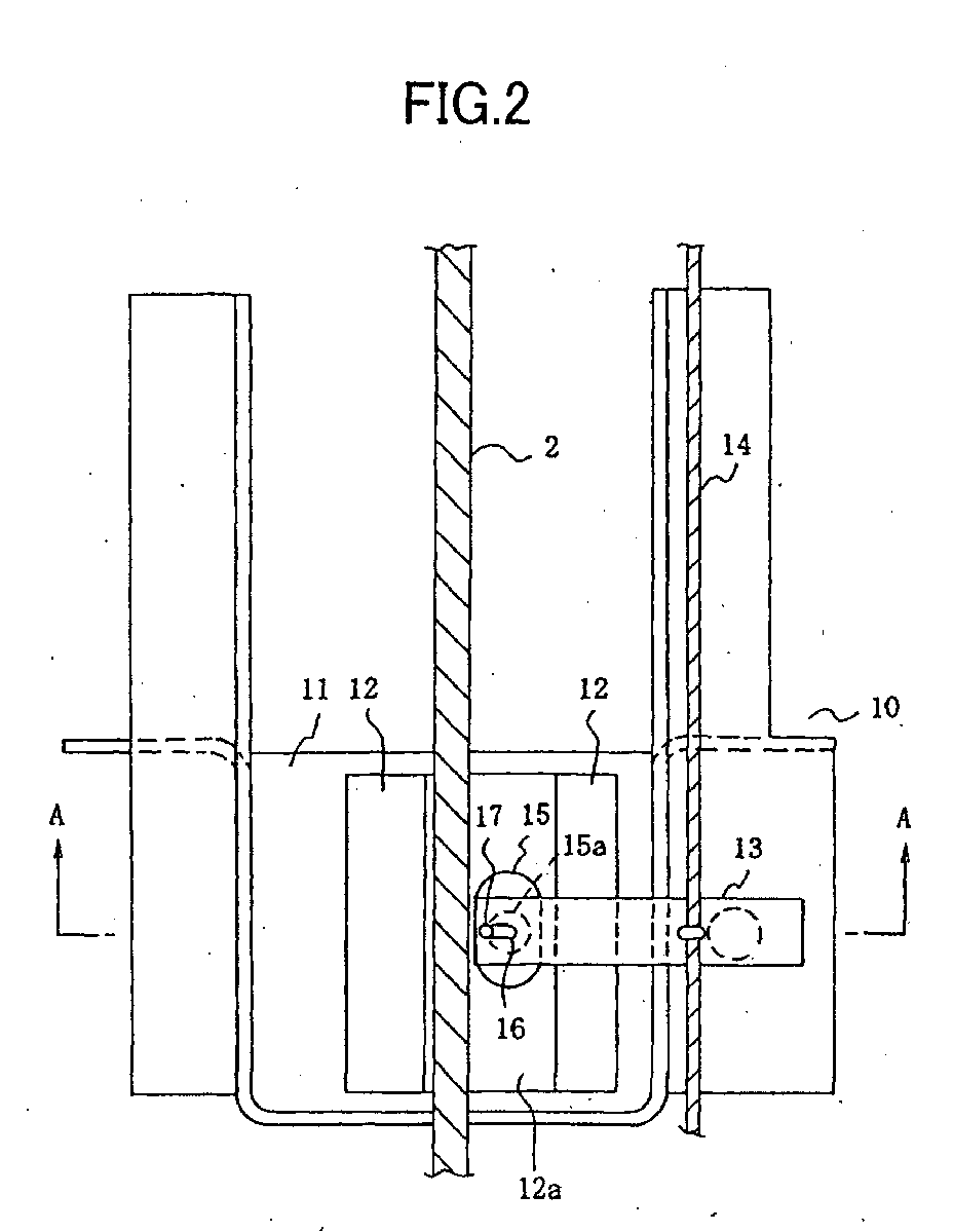
- Fig. 2 is a front view showing the emergency stopping apparatus 10 in this mode of embodiment
- Fig. 3 is a sectional view of the emergency stopping apparatus in this mode of embodiment taken along the line A-A.
- a reference numeral 11 denotes a frame fixed to a lower portion of the elevator car 1.
- a reference numeral 12 denotes a recessed metal holder fixed to a central portion of the frame 11 and adapted to hold a part of the guide rail 2 in a recess 12a.
- a reference numeral 13 denotes a lever fixed rotatably to a side portion of the frame 11.
- a reference numeral 14 denotes a governor rope fixed to the lever 13 and adapted to vertically swing a front-end portion of the lever 13.
- a reference numeral 15 denotes an elliptic roller fixed rotatably to the metal holder 12 by a rotary shaft 15a and held with the guide rail 2 in the recessed wall 12a of the metal holder 12.
- a reference numeral 16 denotes an elongated hole formed in a front-end portion of the lever 13 and extending in the lengthwise direction of the lever 13.
- a reference numeral 17 denotes a pin provided in a projecting state on a circumferential portion of a smaller-diameter section of the roller 15, and inserted slidably into the elongated hole 16.
- the roller 15 has an elliptic shape the smaller diameter of which is shorter than a distance between the guide rail 2 and rotary shaft 15a, and the larger diameter of which is longer than the same distance. Therefore, when the roller 15 is disposed so that the direction in which the guide rail 2 extends and that of the larger diameter of the roll 15 become parallel to each other, a space of a predetermined width is formed between the roller 15 and guide rail 2. When the roller 15 is brought close to the guide rail 2 so that the direction in which the guide rail 2 extends and that in which the shorter diameter of the roll 15 extends become parallel to each other, the roller 15 contacts the guide rail 2.
- the width of the recess 12a is regulated so that this width is larger than the sum of the width of the guide rail 2 and the length of the smaller diameter of the roller 15, and smaller than the sum of the width of the guide rail 2 and the length of the larger diameter of the roller 15.
- the emergency elevator stopping apparatus 10 in this mode of embodiment will now be described.
- the governor rope 14 also moves at the same speed, so that the governor rope 14 does not draw the lever 13. Therefore, the lever 13 always maintains in a horizontal condition with the elongated hole 16 formed therein also becoming horizontal as shown in Fig. 2. Accordingly, the pin 17 inserted into the elongated hole 16 is positioned in a left end thereof. Since the pin 17 is formed on a surface of a smaller-diameter portion of the roller 15, the smaller diameter of the roller 15 becomes horizontal. As a result, a space of a predetermined width is formed between the roller 15 and guide rail 2, so that the roller 15 does not press the guide rail 2.
- the governor detects the increase in speed of the elevator car 1, and grips the governor rope 14 payed out downward at a speed equal to that of the elevator car 1.
- the lever 13 fixed to the governor rope 14 owing to the gripping action of the governor with respect to the governor rope 14 is lifted, and the pin 17 inserted into the elongated hole 16 in the front end portion of the lever 13 is lifted as shown in Fig. 4. Since the pin 17 is fixed to the roller 15, the roller 15 turns clockwise in the drawing around the rotary shaft 15a.
- the roller 15 has not a circular shape but a vertically elongated shape. Therefore, the roller 15 is held between the metal holder 12 and guide rail 2, and thrusts (makes an inroad) into a space therebetween to stop the elevator car emergently.
- the governor detects the increase in speed of the elevator car 1, and grips the governor rope 14 payed out upward at a speed equal to that of the elevator car 1.
- the lever 13 fixed to the governor rope 14 owing to the gripping action of the governor with respect to the governor rope 14 is drawn downward, and the pin 17 inserted into the elongated hole 16 in the front end portion of the lever 13 is drawn downward as shown in Fig. 5. Since the pin 17 is fixed to the roller 15, the roller 15 turns counter-clockwise around the rotary shaft 15a. Therefore, the roller 15 is held between the metal holder 12 and guide rail 2, and thrusts (makes an inroad) into a space therebetween to stop the elevator car 1 emergently.
- the emergency elevator stopping apparatus 10 in this mode of embodiment having a very simple construction in which the elliptic roller 15 is turned in accordance with a vertical movement of the lever 13 to cause the roller 15 to thrust (make an inroad) into the space between the guide rail 2 and metal holder enables the elevator car 1 to stop emergently with a reliability with respect to an increase in speed of the elevator car both in the upward and downward directions. Therefore, the durability and reliability of this emergency elevator stopping apparatus are improved greatly as compared with those of a related art emergency elevator stopping apparatus.
- FIG. 6 is a partial enlarged view showing an example in which a right side wall 40 of a recess 12a provided in a metal holder 12 is inclined in the vertical direction. As shown in this drawing, a lower half portion of the right side wall 40 is inclined so that the width of the recess 12a increases gradually.
- the quantity of a thrust of the roller 15 into a lower half of the right side wall 40 during a turn of the roller 15 in the counter-clockwise direction in the drawing in accordance with an increase in speed of the elevator car 1 moving up is smaller than that of a thrust of the roller 15 into an upper half of the right side wall 40 during a turn of the roller 15 in the clockwise direction in the drawing in accordance with an increase in speed of the elevator car 1 moving down.
- an elevator car stopping force occurring when the speed of the elevator car 1 increases during an upward movement thereof becomes smaller than that occurring when the speed of the elevator car 1 increases during a downward movement thereof.
- the reasons for setting the elevator car stopping force different in the upward and downward directions reside in the following.
- the force of gravity also works downward, so that a large stopping force is needed to stop the elevator car 1.
- the force of gravity works in the contrary direction, so that the elevator car 1 stops by a stopping force smaller than that needed in the above case. Therefore, when the elevator car stopping force is set equal in the upward and downward directions, a reaction force occurring when the elevator car 1 moves up at an increased speed and stops suddenly is large as compared with that occurring in a case where the elevator car 1 moves down at an increased speed and stops suddenly.
- this reaction force gives rise to trouble, a large reaction force occurring due to a sudden stoppage of the elevator car 1 can be reduced by inclining the right side wall 40 of the metal holder 12 just as in this modified example.
- the lower half portion of the right side wall 40 of the metal holder 12 is inclined so that the width of the recess 12a increases gradually.
- the upper half portion of the right side wall 40 of the metal holder 12 may be inclined instead so that the width of the recess 12a decreases gradually. In this case, the same effect as in the modified example is obtained.
- Fig. 7 is a partial enlarged view showing an example in which the shape of a roller 41 is partially changed.
- a right upper side surface portion 41a of the roller 41 is cut off. Therefore, the quantity of a thrust of the right upper side surface portion 41a of the roller 41 into a right side wall 40 during a turn of the roller 41 in the counter-clockwise direction in the drawing in accordance with an increase in speed of the elevator car 1 moving up is smaller than that of a thrust of a right lower side surface portion 41b of the roller 41 into the right side wall 40 during a turn of the roller 41 in the clockwise direction in the drawing in accordance with an increase in speed of the car elevator 1 moving down.
- the elevator car stopping force occurring when the speed of the elevator car 1 increases during an upward movement thereof becomes smaller as compared with that occurring when the speed of the elevator car 1 increases during a downward movement thereof. This enables a large reaction force occurring when the elevator car 1 moves up at an increased speed and stops suddenly to decrease effectively.
- FIG. 8 is a partial enlarged view of an example in which a vertically inclined plate 42 is replaceably fixed to a right side wall 40 of a metal holder 12. As shown in the drawing, the inclined plate 42 is formed so that the width of a lower half portion thereof gradually increases.
- the quantity of a thrust of a roller 15 into the lower half portion of the inclined plate 42 during a turn of the roller 15 in the counter-clockwise direction in the drawing in accordance with an increase in speed of an elevator car 1 moving up is smaller than that of a thrust of the roller 15 into an upper half portion of the inclined plate 42 during a turn of the roller 15 in the clockwise direction in the drawing in accordance with an increase in speed of the elevator car 1 moving down. Accordingly, the elevator stopping force occurring when the speed of the elevator car 1 increases during an upward movement thereof becomes smaller as compared with that occurring when the speed of the elevator car 1 increases during a downward movement thereof. This enables a large reaction force occurring when the elevator car 1 moves up at an increased speed and stops suddenly to decrease effectively. Since the inclined plate 42 is replaceable, the elevator stopping force can be changed as occasion calls, by fixing an inclined plate 42 of a different angle of inclination to the right side wall of a metal holder.
- the upper half portion of the inclined plate 42 in the third modified example is formed so that the width of the recess of the metal holder increases gradually
- the upper half portion thereof may be inclined so that the width of the recess decreases gradually. In this case, the same effect as in the third modified example is obtained.
- the present invention can provide an emergency elevator stopping apparatus, capable of stopping an elevator car easily when the speed of the elevator car increases even during an upward movement thereof, and having a simple construction. Accordingly, this apparatus is suitably utilized, for example, as a household elevator in a low price zone, and as an elevator demanding a high durability.
Landscapes
- Engineering & Computer Science (AREA)
- Mechanical Engineering (AREA)
- Maintenance And Inspection Apparatuses For Elevators (AREA)
Abstract
Description
Claims (6)
- An emergency elevator stopping apparatus provided on an elevator car and adapted to stop the elevator car by pressing a guide rail along which the elevator car is guided, characterized in that:the apparatus is provided with a roller rolling mechanism adapted to press the guide rail when the elevator car moves at a speed in excess of a predetermined level in either the upward or downward direction.
- An emergency elevator stopping apparatus provided on an elevator car and adapted to stop the elevator car by pressing a guide rail along which the elevator car is guided, characterized in that:the apparatus is provided with an elliptic roller disposed rotatably in the vicinity of the guide rail, and having a smaller diameter shorter than a distance between the guide rail and a rotary shaft and a larger diameter longer than the same distance, anda lever adapted to set the direction in which the guide rail extends and that in which the larger diameter of the roller extends, substantially parallel to each other while the elevator car moves at a speed not higher than a predetermined level, and turn the roller when the elevator car moves at a speed in excess of a predetermined level, and thereby cause the roller to press the guide rail.
- An emergency elevator stopping apparatus according to Claim 2, wherein the apparatus is further provided with:an elongated hole formed in a front end portion of the lever and extending in the lengthwise direction of the lever,a pin provided on a circumferential portion of a smaller-diameter section of the roller and slidably inserted into the elongated hole, anda lever driving member adapted to press down a front end portion of the lever when the elevator car moves up at a speed in excess of a predetermined level, and lift the front end portion of the lever when the elevator car moves down at a speed in excess of a predetermined level.
- An emergency elevator stopping apparatus according to Claim 2 or 3, wherein the apparatus is further provided with:a metal holder having a recess for holding a part of the guide rail and the roller therein,the width of the recess being larger than the sum of the width of the guide rail and the smaller diameter of the roller, and smaller than the sum of the width of the guide rail and the larger diameter of the roller.
- An emergency elevator stopping apparatus according to Claim 4, wherein a side wall of the recess is inclined in the vertical direction.
- An emergency elevator stopping apparatus according to Claim 4, wherein the apparatus is further provided with an inclined plate fixed replaceably to a side wall of the recess and extending diagonally in the vertical direction.
Applications Claiming Priority (1)
| Application Number | Priority Date | Filing Date | Title |
|---|---|---|---|
| PCT/JP2001/010325 WO2003045828A1 (en) | 2001-11-27 | 2001-11-27 | Emergency stopper of elevator |
Publications (3)
| Publication Number | Publication Date |
|---|---|
| EP1449800A1 true EP1449800A1 (en) | 2004-08-25 |
| EP1449800A4 EP1449800A4 (en) | 2010-06-23 |
| EP1449800B1 EP1449800B1 (en) | 2017-10-25 |
Family
ID=11737975
Family Applications (1)
| Application Number | Title | Priority Date | Filing Date |
|---|---|---|---|
| EP01274836.4A Expired - Lifetime EP1449800B1 (en) | 2001-11-27 | 2001-11-27 | Emergency stopper of elevator |
Country Status (5)
| Country | Link |
|---|---|
| EP (1) | EP1449800B1 (en) |
| JP (1) | JP4019941B2 (en) |
| KR (1) | KR100620436B1 (en) |
| CN (1) | CN1297466C (en) |
| WO (1) | WO2003045828A1 (en) |
Cited By (1)
| Publication number | Priority date | Publication date | Assignee | Title |
|---|---|---|---|---|
| EP1733992A1 (en) * | 2005-06-17 | 2006-12-20 | Inventio Ag | Safety brake device |
Families Citing this family (5)
| Publication number | Priority date | Publication date | Assignee | Title |
|---|---|---|---|---|
| JP2007131388A (en) * | 2005-11-09 | 2007-05-31 | Chiyuuritsu Denki Kk | Fall prevention device for lifting device |
| US8297413B2 (en) | 2007-06-21 | 2012-10-30 | Mitsubishi Electric Corporation | Safety device for elevator and rope slip detection method using drive sheave acceleration |
| KR101036020B1 (en) | 2011-01-14 | 2011-05-23 | 세계실업(주) | Fall prevention device of industrial lift |
| CN105947832B (en) * | 2016-06-28 | 2017-12-19 | 爱默生电梯有限公司 | A kind of instantaneous safety for villa elevator |
| CN105883523B (en) * | 2016-06-28 | 2017-12-19 | 爱默生电梯有限公司 | A kind of villa elevator instantaneous safety |
Family Cites Families (8)
| Publication number | Priority date | Publication date | Assignee | Title |
|---|---|---|---|---|
| GB1368974A (en) * | 1971-11-26 | 1974-10-02 | Ace Machinery Ltd | Brakes for materials hoists |
| DE3422854A1 (en) * | 1984-06-20 | 1986-01-02 | F. Zimmermann GmbH, 7306 Denkendorf | Safety device for a machine |
| JPS6422788A (en) * | 1987-07-20 | 1989-01-25 | Mitsubishi Electric Corp | Elevator |
| JPH0522857U (en) * | 1991-09-06 | 1993-03-26 | 石川島播磨重工業株式会社 | Spline fitting |
| DE59406874D1 (en) * | 1993-08-24 | 1998-10-15 | Garaventa Holding Ag | Catching and blocking device for a carriage of an inclined or vertical elevator guided on running rails |
| US5713434A (en) * | 1995-07-07 | 1998-02-03 | Otis Elevator Company | Elevator safety system |
| DE19606861C2 (en) * | 1996-02-23 | 1999-02-04 | Gerhard Schlosser | Brake safety device for lifts |
| ATE226554T1 (en) * | 1997-08-21 | 2002-11-15 | Aufzugstechnologie Schlosser G | BRAKE DEVICE |
-
2001
- 2001-11-27 JP JP2002589150A patent/JP4019941B2/en not_active Expired - Fee Related
- 2001-11-27 CN CNB01823075XA patent/CN1297466C/en not_active Expired - Fee Related
- 2001-11-27 KR KR1020037012592A patent/KR100620436B1/en not_active Expired - Fee Related
- 2001-11-27 WO PCT/JP2001/010325 patent/WO2003045828A1/en not_active Ceased
- 2001-11-27 EP EP01274836.4A patent/EP1449800B1/en not_active Expired - Lifetime
Cited By (2)
| Publication number | Priority date | Publication date | Assignee | Title |
|---|---|---|---|---|
| EP1733992A1 (en) * | 2005-06-17 | 2006-12-20 | Inventio Ag | Safety brake device |
| US7299898B2 (en) | 2005-06-17 | 2007-11-27 | Inventio Ag | Progressive safety device |
Also Published As
| Publication number | Publication date |
|---|---|
| JP4019941B2 (en) | 2007-12-12 |
| KR100620436B1 (en) | 2006-09-12 |
| WO2003045828A1 (en) | 2003-06-05 |
| KR20030089705A (en) | 2003-11-22 |
| EP1449800B1 (en) | 2017-10-25 |
| CN1297466C (en) | 2007-01-31 |
| JPWO2003045828A1 (en) | 2005-04-07 |
| EP1449800A4 (en) | 2010-06-23 |
| CN1494512A (en) | 2004-05-05 |
Similar Documents
| Publication | Publication Date | Title |
|---|---|---|
| US8006806B2 (en) | Emergency brake of elevator | |
| US7753176B2 (en) | Emergency stop system of elevator | |
| EP1607359B1 (en) | Emergency brake apparatus of elevator | |
| US8763763B2 (en) | Elevator apparatus having car position detection | |
| CN111712455A (en) | Emergency stop devices and elevators | |
| EP1449800B1 (en) | Emergency stopper of elevator | |
| KR101783323B1 (en) | Lift falling prevention system | |
| JPWO2019069453A1 (en) | Elevator safety gear | |
| JP2010533112A (en) | Lifting hook | |
| CN101172553A (en) | Cordless speed limiting system of elevator | |
| JP2626408B2 (en) | Emergency stop device for elevator | |
| JP4597049B2 (en) | Elevator configuration without machine room with small overhead | |
| JPH09104572A (en) | Elevator emergency stop device | |
| KR101239403B1 (en) | double type safety device for elevator | |
| JP5081137B2 (en) | Elevator braking device | |
| JP5464931B2 (en) | elevator | |
| JP2003073054A (en) | Car hoisting device of elevator | |
| CN211945794U (en) | Elevator one-way and two-way speed limiting tensioning device | |
| JP5191825B2 (en) | Self-propelled elevator | |
| JP2010184778A (en) | Counterweight device | |
| EP1795484B1 (en) | Elevator apparatus | |
| KR102445143B1 (en) | ropeless elevator system | |
| CN222598687U (en) | Detection processing jig for elevator base parts | |
| JP7643490B2 (en) | Elevator | |
| CN219792093U (en) | Anti-collision safety device of construction elevator |
Legal Events
| Date | Code | Title | Description |
|---|---|---|---|
| PUAI | Public reference made under article 153(3) epc to a published international application that has entered the european phase |
Free format text: ORIGINAL CODE: 0009012 |
|
| 17P | Request for examination filed |
Effective date: 20040528 |
|
| AK | Designated contracting states |
Kind code of ref document: A1 Designated state(s): AT BE CH CY DE DK ES FI FR GB GR IE IT LI LU MC NL PT SE TR |
|
| AX | Request for extension of the european patent |
Extension state: AL LT LV MK RO SI |
|
| RAP1 | Party data changed (applicant data changed or rights of an application transferred) |
Owner name: MITSUBISHI DENKI KABUSHIKI KAISHA |
|
| A4 | Supplementary search report drawn up and despatched |
Effective date: 20100525 |
|
| 17Q | First examination report despatched |
Effective date: 20101216 |
|
| REG | Reference to a national code |
Ref country code: DE Ref legal event code: R079 Ref document number: 60150652 Country of ref document: DE Free format text: PREVIOUS MAIN CLASS: B66B0005180000 Ipc: B66B0005200000 |
|
| GRAP | Despatch of communication of intention to grant a patent |
Free format text: ORIGINAL CODE: EPIDOSNIGR1 |
|
| RIC1 | Information provided on ipc code assigned before grant |
Ipc: B66B 5/20 20060101AFI20170418BHEP |
|
| INTG | Intention to grant announced |
Effective date: 20170516 |
|
| RBV | Designated contracting states (corrected) |
Designated state(s): DE FR NL |
|
| GRAS | Grant fee paid |
Free format text: ORIGINAL CODE: EPIDOSNIGR3 |
|
| GRAA | (expected) grant |
Free format text: ORIGINAL CODE: 0009210 |
|
| AK | Designated contracting states |
Kind code of ref document: B1 Designated state(s): DE FR NL |
|
| REG | Reference to a national code |
Ref country code: DE Ref legal event code: R096 Ref document number: 60150652 Country of ref document: DE |
|
| REG | Reference to a national code |
Ref country code: NL Ref legal event code: MP Effective date: 20171025 |
|
| PG25 | Lapsed in a contracting state [announced via postgrant information from national office to epo] |
Ref country code: NL Free format text: LAPSE BECAUSE OF FAILURE TO SUBMIT A TRANSLATION OF THE DESCRIPTION OR TO PAY THE FEE WITHIN THE PRESCRIBED TIME-LIMIT Effective date: 20171025 |
|
| REG | Reference to a national code |
Ref country code: DE Ref legal event code: R097 Ref document number: 60150652 Country of ref document: DE |
|
| PLBE | No opposition filed within time limit |
Free format text: ORIGINAL CODE: 0009261 |
|
| REG | Reference to a national code |
Ref country code: FR Ref legal event code: ST Effective date: 20180731 |
|
| STAA | Information on the status of an ep patent application or granted ep patent |
Free format text: STATUS: NO OPPOSITION FILED WITHIN TIME LIMIT |
|
| 26N | No opposition filed |
Effective date: 20180726 |
|
| PG25 | Lapsed in a contracting state [announced via postgrant information from national office to epo] |
Ref country code: FR Free format text: LAPSE BECAUSE OF NON-PAYMENT OF DUE FEES Effective date: 20171226 |
|
| PGFP | Annual fee paid to national office [announced via postgrant information from national office to epo] |
Ref country code: DE Payment date: 20191112 Year of fee payment: 19 |
|
| REG | Reference to a national code |
Ref country code: DE Ref legal event code: R119 Ref document number: 60150652 Country of ref document: DE |
|
| PG25 | Lapsed in a contracting state [announced via postgrant information from national office to epo] |
Ref country code: DE Free format text: LAPSE BECAUSE OF NON-PAYMENT OF DUE FEES Effective date: 20210601 |