Technical Field to which the Invention belongs
The present invention relates to an inflator suitable for
an air bag system for an automobile. The present invention also
provides an inflator in which pieces of a broken rupturable
plate or combustion residues of a gas generating agent is
prevented from flowing out of the inflator.
Prior Art
As an inflator used in an air bag system for an automobile,
there are a type in which an air bag is inflated by using only
combustion gas of a gas generating agent and also a type in which
an air bag is inflated by using combustion gas of a gas generating
agent and pressurized gas. In either type of the inflators,
it is required that combustion residues generated at the time
of combustion of the gas generating agent, for example, powdery
metal or metal oxide generated due to components of the gas
generating agent is never discharged into the air bag.
Therefore, such a trial has been made that generation of
combustion residues is suppressed by changing composition of
the gas generating agent or a structure of the inflator.
In addition, there is a type in which an air bag is inflated
by using only pressurized gas. However, with a development of
a inflator for an inflating-type safety system for an automobile,
an inflator using pressurized gas and a gas generating agent
together is attracting attention.
Also, such a trial has been made that a filter is disposed
to prevent pieces of a broken rupturable plate from flowing
outside, or that generation of combustion residues is
suppressed by changing composition of the gas generating agent,
or a structure of the inflator.
As the related prior arts, there are JP-A 9-76870, US-A
3,966,226 and US-A 4,018,457.
An essential requirement in designing the inflator is
that an air bag has to be inflated by a predetermined amount
within a predetermined time to actuate the air bag effectively,
and various proposals about the structure has been made
conventionally. For example, there is JP-A 8-282427. As other
related prior arts, there have been known JP-B 44-10443, US-A
6,189,922, and JP-A 2002-166817.
Since the inflator is produced for an automobile, the
weight and size of the inflator which influences a weight of
an automobile are important design requirements. Accordingly,
further reduction in weight of an inflator is required while
maintaining its original functions.
Disclosure of the Invention
An object of the present invention is to provide an
inflator in which a gas generating agent and a structure of the
inflator are improved and combined to obtain a synergistic
effect so that an amount of combustion residues discharged out
of the inflator is suppressed.
The present invention (I-1) provides, as one means for
solving the above problem, an inflator in which an air bag is
inflated by combustion gas generated by combustion of a gas
generating agent and a pressurized medium, comprising a means
for making the combustion gas strike against one or at least
wall surfaces so that combustion residues adhere to the one or
at least two wall surfaces, and also a means for making the
combustion gas contact with the pressurized medium so that the
combustion residues contained in combustion gas are cooled and
solidified due to a temperature difference, wherein a melting
point of the combustion residues generated due to combustion
of the gas generating agent is equal to or more than a discharging
temperature of a gas generated from the gas generating agent.
Further, the present invention (I-2) provides, as another
means for solving the above problem, an inflator in which an
air bag is inflated by an action of combustion gas generated
by combustion of a gas generating agent and a pressurized medium,
comprising a means for changing a flowing direction of
combustion gas to make combustion residues in the combustion
gas adhere to one or at least wall surfaces, and also a means
for making the combustion gas contact with the pressurized
medium so that the combustion residues in combustion gas are
cooled and solidified due to a temperature difference, wherein
the melting point of the combustion residues generated due to
combustion of the gas generating agent is equal to or more than
a discharging temperature of a gas generated from the gas
generating agent.
The above-described inventions are provided with the
means for arresting the combustion residues contained in
combustion gas of the gas generating agent respectively, the
following advantageous effects (1) to (3) can be obtained.
Advantageous effect (1)
By associating the discharging temperature of a gas
generated from a gas generating agent and the melting point of
a combustion residue contained in the combustion gas,
generation of a massive (slag-like) combustion residue can be
promoted. The temperature of the discharged gas of the gas
generating agent can be obtained on the basis of a pressure
inside the tank (an actually measured value) and a generated
gas amount obtained at the time of being burnt in the tank having
a predetermined volume and further the specific heat of the
generated gas, for example, according to the following formula
(values other than T2 in the formula can be obtained by
calculations or the like). When the melting point of the
residue becomes sufficiently higher than the temperature of the
discharged gas (not less than 100°C, preferably not less than
500°C), the combustion residue can be easily solidified and.
becomes massive (slag-like), and it remains inside the inflator
to be suppressed from being discharged outside of the inflator.

In the formula, the meanings of symbols are as follows:
Advantageous effect (2)
By cooling the combustion gas due to a temperature
difference from the pressurized medium, combustion residues can
be solidified. When the combustion gas with a high temperature
and the pressurized medium with a lower temperature contact with
each other, the combustion residues with a high temperature are
cooled and solidified to becomes massive (slag-like) and
remains inside the inflator so that the residues are suppressed
from being discharged outside the inflator. The advantageous
effect (2) can be further improved owing to a synergism with
the advantageous effect (1).
Advantageous effect (3)
By making combustion gas flow strike against a wall
surface, combustion residues can adhere to the wall surface.
Since the combustion residues contained in the combustion gas
has a high temperature and the pressurized medium has a lower
temperature, the combustion residues is solidified when the
residues contact with the pressurized medium as in the above
advantageous effect (2), and further, the combustion residues
adhere to the wall surface by making the combustion residues
in the course of solidifying strike against the wall surface
and thereby, the amount of combustion residues discharged
outside of the inflator can be reduced. The advantageous effect
(3) can be further improved owing to a synergism with the
advantageous effects (1) and (2).
In order to easily obtain the advantageous effects (1)
to (3) in the respective above inventions, a preferable inflator
comprises an outer shell made of a cylindrical pressurized
medium chamber housing, a pressurized medium chamber charged
with a pressurized medium, a gas generator which is connected
to one end of the pressurized medium chamber and includes an
ignition means and a gas generating agent accommodated in a gas
generator housing, and a diffuser portion connected to the other
end of pressurized medium chamber, wherein a first rupturable
plate closes between the pressurized medium chamber and the gas
generator, a second rupturable plate closes between the
pressurized medium chamber and the diffuser portion, and
further, a cap, which has a gas ejecting hole in at least one
of the side surface and end surface, covers the first rupturable
plate from the pressurized medium chamber side.
As describe above, the first rupturable plate closes
between the pressurized medium chamber and the gas generator,
and thereby, even when the gas generating agent is burnt, a
sufficient temperature difference of the combustion gas and the
pressurized medium can be obtained to exhibit a solidifying
effect of the combustion residues. Accordingly, even when the
inflator is kept under a high temperature (for example, inside
an automobile including an air bag apparatus provided with an
inflator, in the summer), a temperature of the pressurized
medium is much lower than a discharging temperature of the gas
generating agent, thereby exhibiting a solidifying effect of
the combustion residues. However, in case of not having the
first rupturable plate, the pressurized medium is heated by the
combustion heat of the gas generating agent, so that the
temperature difference between the pressurized medium and the
discharged gas becomes small, thereby spoiling the solidifying
effect of the combustion residues.
Also, since the gas generating agent exist under a normal
pressure, deterioration of the gas generating agent due to
pressure is reduced as compared with a case of existing under
a high pressure. Further, by providing the cap having a gas
ej ecting hole in at least one of a side surface and an end surface,
the combustion gas easily strikes against a wall surface of the
pressurized medium chamber housing. Incidentally, in order to
enhance an arresting effect of the combustion residue, a cap
can also be provided in the second rupturable plate side.
Also, the present invention (I-4) provides, as another
means for solving the above problem, an inflator comprising an
outer shell made of a cylindrical pressurized medium chamber
housing, a pressurized medium chamber charged with a
pressurized medium, a gas generator which is connected to one
end of the pressurized medium chamber and includes an ignition
means and a gas generating agent accommodated in a gas generator
housing, and a diffuser portion connected to the other end of
pressurized medium chamber, wherein a first rupturable plate
closes between the pressurized medium chamber and the gas
generator, a second rupturable plate closes between the
pressurized medium chamber and the diffuser portion, a cap
covers the first rupturable plate from the pressurized medium
chamber side and further, at least one selected from the
following requirements (a) to (c) is provided.
Since the above-described inventions are provided with
the requirements (a) to (c), the following advantageous effects
(4) to (6) can be obtained in addition to the advantageous
effects (2) and (3).
Advantageous effect (4)
As described in the requirement (a) , when the inner wall
surface of the pressurized medium chamber housing is rough, the
combustion residues are easily caught and arrested by uneven
part of the rough surface, so that discharging of the combustion
residues is suppressed.
In order to exhibit better the advantageous effect (4),
in the requirement (a), preferably, the inner wall surface of
the pressurized medium chamber housing forming the pressurized
medium chamber is provided with a groove (s) formed continuously
or discontinuously in the circumferential direction
(preferably, its depth is not less than 0.1 mm, and more
preferably, not less than 0.2 mm). By forming such a groove,
the housing weight can be reduced corresponding to the groove.
Advantageous effect (5)
As described in the requirement (b), by restricting the
opening direction of the gas ejecting hole provided in the cap,
the number of contacts of the combustion gas and the wall surface
can be increased (that is, a contacting time can be elongated),
so that the combustion residues easily adhere to the wall
surface, and discharging of the combustion residues outside the
inflator is suppressed.
In order to exhibit better the advantageous effect (5),
in the requirement (b), the aspect in which the gas ejecting
hole is provided in a side surface of the cap to be oriented
towards the gas generator; the aspect in which the gas ejecting
hole is provided in a side surface of the cap and a member for
circumferentially restricting the ejecting direction of
combustion gas from the gas ejecting hole is provided; and the
aspect in which the gas ejecting hole is provided in an end
surface of the cap and a member for circumferentially
restricting the ejecting direction of combustion gas from the
gas ejecting hole is provided can be employed.
Advantageous effect (6)
As described in the requirement (c), combustion gas
ejected from the gas ejecting hole strikes against the barrier
member, and therefore, combustion residues first adhere to the
barrier member to be arrested. And a flow of the combustion
gas is disturbed by striking against the barrier member, so that
the number of times of contacts of combustion gas and the wall
surface can be increased (that is, the contacting time can be
elongated), and consequently, the advantageous effect (5) is
also obtained substantially and discharging of the combustion
residues outside the inflator is suppressed.
In order to exhibit better the advantageous effect (6),
in the requirement (c), the following aspects can be employed;
An aspect in which the barrier member is cylindrical, one
end thereof is integrated with the end surface of the cap and
closed, the other end is opened, and a side surface is formed
to face, with a gap, the gas ejecting hole provided in a side
surface of the cap, and the combustion gas moves from the opened
end after the combustion gas strikes against an inner wall of
the side surface on the cylindrical member.
An aspect in which the barrier member is disk-shaped,
integrated with end surface of the cap and is extended from the
end surface of the cap towards an inner wall surface of the
pressurized medium chamber housing, and after the combustion
gas ejected from the gas ejecting hole provided in the side
surface of the cap strikes against a peripheral edge portion
of the barrier member, it moves from a clearance between the
inner wall surface of the pressurized medium chamber housing
and the peripheral edge portion of the barrier member.
An aspect in which the barrier member is disk-shaped,
integrated with the end surface of the cap and is extended from
the end surface of the cap towards an inner wall surface of the
pressurized medium chamber housing to make a peripheral edge
portion thereof abut on the inner wall surface, a gas passing
port is provided in the peripheral edge portion of the barrier
member and a member for circumferentially restricting an
ejecting direction of gas from the gas passing port is provided,
and combustion gas ejected from the gas ejecting hole provided
in the side surface of the cap is ejected from the gas passing
port.
The inflator of the above-described invention can be
provided with the requirements (a) and (b), the requirements
(a) and (c), the requirements (b) and (c), or the requirements
(a), (b) and (c).
Further, in the inflator of the above-described invention,
such an aspect can be employed that the cap has a flange portion
formed by bending an opening peripheral edge portion outwardly
and the gas generator housing is fixed at the flange portion
by crimping part of the gas generator housing.
Further, in the inflator of the above-described invention,
such an aspect can be employed that a pressurized medium
charging hole is formed in a side surface of the pressurized
medium chamber housing, and the charging hole is closed by a
pin after the pressurized medium is charged. In the inflator
of the above-described invention, such an aspect can be employed
that the pin is protruding into the pressurized medium chamber
and a protruding portion thereof has such a length that
combustion gas flow of the gas generating agent strikes against
the protruding portion. By securing some length in the
protruding portion of the pin in this manner, combustion gas
is made to strike against the pin so that the combustion residues
adhere to the pin.
Also in the above-described invention, the advantageous
effect (1) can further be exhibited by using a gas generating
agent in which a melting point of the combustion residue
generated by combustion of the gas generating agent is not less
than a discharging temperature of gas generated from the gas
generating agent.
In the above-described invention, such an aspect can be
employed that the pressurized medium chamber housing is
symmetrical in the axial and radial directions. By employing
such a symmetrical shape, the orientation of the pressurized
medium chamber housing does not have to be adjusted at a time
of assembling, so that an assembling work is facilitated.
In the above-described invention, such an aspect can be
employed that the gas generator housing and the pressurized
medium chamber housing are connected by resistance-welding.
The gas generating agent used in the present invention
can be determined in relation with composition of the
pressurized medium as follows:
The pressurized medium comprises an inert gas such as
argon or helium (nitrogen is also included in the inert gas in
the present invention). When the pressurized medium has a
composition which does not include oxygen substantially, the
argon works to promote the thermal expansion of the pressurized
medium, and helium is preferably contained because the leakage
of the pressurized medium can be detected easily and
consequently, distribution of imperfect products can be
prevented. Also, a preferable pressurized medium does not
include oxygen, but oxygen may be included to promote combustion
of the gas generating agent. In case of including oxygen, an
amount of addition thereof is preferably 10 mole% or less, more
preferably 5 mole% or less. A charging pressure of the
pressurized medium is preferably 10,000 to 70,000 kPa, more
preferably 30,000 to 60,000 kPa.
As the gas generating agent, for example, it is possible
to use a material including fuel and oxidizing agent, or fuel,
oxidizing agent and slag-forming agent, being mixed with binder
if required, and formed into a desired shape. If such a gas
generating agent is used, a gas generated by combustion of the
agent can be used for inflating and developing an air bag
together with the pressurized medium. Especially, when the gas
generating agent including the slag-forming agent is used, slag
is easily made, so that an amount of mist-like combustion
residues discharged from the inflator can be largely reduced.
However, in case of reducing a charged amount of gas generating
agent and generated residues, it is unnecessary to use a
slag-forming agent.
A preferable fuel can be one or at least two selected from
the group consisting of guanidine derivatives such as
nitroguanidine (NQ), guanidine nitrite (GN), guanidine
carbonate, amino nitroguanidine, amino guanidine nitrite,
amino guanidine carbonate, diamino guanidine nitrite, diamino
guanidine carbonate, and triamino guanidine nitrite. As fuel,
one or at least two selected from the group consisting of
tetrazole and tetrazole derivatives can be used.
As the oxidizing agent, one or at least two selected from
the group consisting of strontium nitrate, potassium nitrate,
ammonium nitrate, potassium perchlorate, copper oxide, ferrous
oxide, a basic copper nitrate are preferably used.
As the slag-forming agent, one or at least two selected
from the group consisting of acid clay, talc, bentonite,
diatomaceous earth, kaolin, silica, alumina, sodium silicate,
silicone nitride, silicon carbide, hydrotalsite, and a mixture
thereof are preferably used.
As the bonding agent, one or at least two selected from
the group consisting of sodium salt of carboxymethylcellulose,
hydroxyethyl cellulose, starch, polyvinyl alcohol, guar gum,
microcrystal cellulose, polyacrylamide and calcium stearate
are preferably used.
When the pressurized medium and the gas generating agent
composed in the above manner are used, a mole ratio (A/B) of
an amount of the pressurized medium (A moles) and an amount of
the gas generated by combustion of the gas generating agent (B
moles) is adjusted to preferably 0.2 to 10, more preferably 0.4
to 4. The mole ratio A/B may be described as a mole ratio A1/A2
in the following explanation.
By adjusting the mole ratio of an amount of the
pressurized medium and an amount of the gas generated by
combustion of the gas generating agent in this manner, a delay
in rising of an inflator internal pressure can be prevented and
an excessive rising of an internal pressure of the inflator can
be prevented. Thus, an internal pressure of the inflator can
be controlled at a time of combustion of the gas generating agent,
and thereby, the volume of the pressurized medium chamber
housing is reduced (that is, the length and/or the width
(diameter) of the pressurized medium chamber housing is
reduced), and even if the internal pressure rises
correspondingly, an internal pressure of the inflator at a time
of combustion can be prevented from rising excessively.
Incidentally, in the inflator of the present invention, a weight
ratio (X/Y) of a weight (X) of the pressurized medium and a weight
(Y) of the gas generating agent is preferably 0.1 to 7, more
preferably 0.5 to 5. The weight ratio (X/Y) may be described
as a mass ratio B1/B2 in the following explanation.
The gas generating agent used in the present invention
can include 20 to 60 mass% of nitroguanidine as the fuel and
80 to 40 mass% of the oxidizing agent, and preferably, 30 to
40 mass% of nitroguanidine as the fuel and 70 to 60 mass% of
strontium nitrate as the oxidizing agent. Further, the bonding
agent (sodium carboxymethylcellulose or the like) and the
slag-forming agent (acid clay or the like) can further be mixed
in addition to the fuel and the oxidizing agent. In this case,
it is preferable that the fuel is 20 to 60 mass%, the oxidizing
agent is 40 to 65 mass%, the bonding agent is 3 to 12 mass%
(preferably 4 to 12 mass%), and the slag-forming agent is 1 to
20 mass% (preferably 3 to 7 mass%).
According to the inflator of the present invention,
combustion residues contained in the combustion gas of the gas
generating agent can be suppressed from being discharged
outside the inflator.
Next, the present invention (II-1) provides, as one means
for solving the problem, an inflator in which an air bag is
inflated with combustion gas due to combustion of a gas
generating agent and pressurized gas, comprising a pressurized
gas chamber which has a outer shell formed by a cylindrical
pressurized gas chamber housing and is filled with pressurized
gas, a gas generator which is connected to the pressurized gas
chamber and includes an ignition means and a gas generating
agent accommodated in a gas generator housing, and a diffuser
portion which is connected to a different portion from the
pressurized gas chamber, a first rupturable plate closing
between the pressurized gas chamber and the gas generator, and
a second rupturable plate closing between the pressurized gas
chamber and the diffuser portion, wherein
the diffuser portion is a cap having a plurality of gas
discharging holes through which gas passes, and at least one
of pieces produced by the broken first and second rupturable
plates and residues (combustion residues) contained in
combustion gas generated by combustion of the gas generating
agent is prevented from flowing outside the inflator.
In this invention, any aspect can be employed such that
the diffuser portion is a cap, or that a cap is disposed inside
the diffuser portion, and further, the aspect in which the
diffuser portion is fixed by welding to the pressurized gas
chamber housing, or the aspect in which the diffuser portion
is integrated with the pressurized gas chamber housing can be
employed.
In this invention, the diffuser portion removes either
or both of pieces of the broken first and second rupturable
plates and a combustion residue to prevent them from flowing
outside the inflator or to reduce an outflow amount thereof.
In an inflator of the present invention (II-2), a cap,
having a plurality of gas discharging holes through which gas
passes and preventing at least one of pieces of the broken first
rupturable plate and combustion residues of the gas generating
agent from flowing outside the inflator, is disposed inside the
pressurized gas chamber to cover the first rupturable plate from
the pressurized gas chamber side.
In this invention, broken pieces produced by breaking of
the first rupturable plate and combustion residues are removed
by the cap disposed inside the pressurized gas chamber, thereby
preventing them from flowing outside the inflator or to reduce
an outflow amount thereof.
In an inflator of the present invention (II-3), a cap,
having a plurality of gas discharging holes through which gas
passes and preventing at least one of pieces of the broken first
rupturable plate and combustion residues of the gas generating
agent from flowing outside the inflator, is disposed inside the
pressurized gas chamber to cover the first rupturable plate from
the pressurized gas chamber side.
In this invention, pieces produced by breaking of the
first rupturable plate and combustion residues are removed by
the cap disposed inside the pressurized gas chamber, thereby
preventing them from flowing outside the inflator or to reduce
an outflow amount thereof.
It is preferable that the cap of the above-described
invention comprises a cylindrical member having one end opened
and the other end closed, and has a plurality of gas discharging
holes in at least a peripheral surface thereof.
In the cap of the above-described invention, preferably,
the relationship between a distance L between a closed end
surface of the cap and a gas discharging hole nearest to the
closed end surface and a diameter D of the rupturable plate
satisfies the following formula: L ≥ D/2. In this case, the
distance L is preferably 3 to 8 mm, more preferably 4 to 8 mm,
and most preferably 5 to 8 mm.
The diameters of a plurality of the gas discharging holes
in the cap of the above-described invention are preferably 0.5
to 2 mm and more preferably 0.5 to 1.2 mm, and the total opening
area of a plurality of the ejecting holes in a screen is
preferably 20 to 1000 mm2 and more preferably 100 to 500 mm2.
It is preferable that the cap of the above-described
invention is disposed such that the axial direction of the cap
and the axial direction of the pressurized gas chamber housing
coincide with each other.
With the above-described cap of the invention, the
following advantageous effects (IIa) to (IIc) can be obtained.
(IIa) When the cap is disposed such that the axial
direction the cap and the axial direction of the pressurized
gas chamber housing coincide with each other, pressurized gas
strikes against the closed end surface of the cap and then
changes its flow direction to flow out from the ejecting holes
in the peripheral surface. Because the gas changes its outflow
direction, foreign materials (pieces of the broken rupturable
plate or the like) easily remain in a pocket portion from the
closed end surface of the screen to the ejecting hole nearest
thereto. Incidentally, by mounting the screen at the flange
portion in the above manner, no gap is produced between the
screen and an inner wall of a gas discharging port, and foreign
materials are prevented from flowing out without passing
through the screen.
(IIb) When the inflator is actuated and the rupturable
plate is broken by an igniter, a central portion of the
rupturable plate is positioned near to the igniter and a
pressure of the pressurized medium applied from the opposite
side becomes the maximum at the central portion, and therefore,
the rupturable plate is liable to be broken from the central
portion in any event. For this reason, the maximum length of
the foreign material produced by breaking the rupturable plate
has a length corresponding to a radius of the rupturable plate.
Thereby, as described above, if the relationship of L ≥ D/2 is
satisfied, the depth (L) of the pocket portion becomes equal
to or more than the length (D/2) of the foreign materials, so
that the foreign materials become easier to remain in the pocket
portion. That is, the above-described advantageous effect
(IIa) is further enhanced.
(IIc) Since the pressurized medium enters from the
opening of the screen to be discharged through the ejecting hole
on the peripheral surface, foreign materials contained in the
pressurized medium is prevented from leaking outside the
inflator, and at the same time, outflow pressure of the
pressurized medium is also controlled. Further, by
controlling the outflow pressure (an outflow amount per unit
time) of the pressurized medium with the screen at a time of
actuation, the outflow pressure of the pressurized medium is
prevented from being influenced by broken state of the
rupturable plate.
The present invention (II-10) provides an inflator
according to any one of the inflators described in the above
(II), including means for changing the flow direction of the
combustion gas by the cap, making combustion residues contained
in the combustion gas adhere to one or at least two portions
of the wall surface, further making the combustion gas contact
with the pressurized gas, and cooling and solidifying the
combustion residues contained in the combustion gas due to a
temperature difference, wherein the melting point of the
combustion residues generated due to combustion of the gas
generating agent is equal to or more than a discharging
temperature of a gas generated from the gas generating agent.
In the present invention (II-10), the advantageous
effects (1) to (3) of the above-described invention (I) can be
obtained in addition to the above-described operations (IIa)
to (IIc).
Further, in the present invention (II-10), with the first
rupturable plate closing between the pressurized gas chamber
housing and the gas generator, a sufficient temperature
difference can be obtained between the combustion gas and the
pressurized gas and a solidifying action of the combustion
residues can be exhibited even when the gas generating agent
is burnt. Accordingly, even when the inflator is left in a high
temperature (for example, inside an automobile including an air
bag apparatus provided with an inflator, in the summer), the
temperature of the pressurized gas becomes remarkably lower
than the discharged gas temperature of the gas generating agent
so that the solidifying action of the combustion residue is
exhibited. However, without the first rupturable plate, the
pressurized gas is heated by combustion heat of the gas
generating agent, and thereby, the temperature difference
between the pressurized gas and the discharge gas becomes small,
so that the solidifying action of the combustion residue is
weaken.
Also, since the gas generating agent is kept under a
normal pressure, its deterioration due to pressure is smaller
than that in case of being kept under a high pressure. Further,
since the cap having the gas discharging hole in at least one
of the side surface and the end surface is provided, combustion
gas easily strikes against the wall surface of the pressurized
gas chamber housing. Incidentally, in order to enhance the
arresting effect of the combustion residues, a cap can also be
provided on the second rupturable plate side.
The invention (II-11) provides the inflator according to
any one of the inflators described in the above invention (II)
and further provided with at least one selected from the
requirements (a), (b) and (c) of the above invention (I).
Since the present invention is provided with at least one
selected from the requirements (a), (b) and (c), the above
advantageous effects (4) to (6) can be obtained in addition to
the advantageous effects (2) and (3). Plural combination can
be applied to the requirements (a), (b) and (c) as in the above
(I).
Further, the invention (II) can take an aspect in which
the cap has a flange portion and is fixed as in the invention
(I).
Further, the invention (II) can take an aspect in which
a pressurized-medium charging hole, a pin and a protruding
portion are provided as in the invention (I).
Also in the invention (II), the advantageous effect(1)
can be exhibited as in the above (I). Further, a relationship
among the pressurized gas chamber housing, joining of the gas
generator housing and the pressurized gas chamber housing,
compositions of the gas generating agent and pressurized gas
can be provided as in the invention (I).
The gas generating agent and the pressurized gas used in
the present invention (II) is similar to those in the invention
(I).
By adjusting the mole ratio of an amount of the
pressurized gas and an amount of gas generated by combustion
of the gas generating agent in the above manner, an charging
amount of the pressurized gas can be reduced. Thereby, even
when a volume of the pressurized gas chamber housing is reduced
(that is, a length and/or a width (diameter) of the pressurized
gas chamber housing is reduced), the same pressure as that
before a volume is reduced can be maintained without increasing
a charging pressure of the pressurized gas (= the internal
pressure in the pressurized gas chamber housing).
Incidentally, in the inflator of the present invention, the
weight ratio (X/Y) of the weight (X) of the pressurized gas and
the weight (Y) of the gas generating agent is preferably 0.1
to 7, and more preferably 0.5 to 5.
According to the inflator of the present invention,
pieces of the broken reputurable plate contained in a gas and
combustion residues contained in combustion gas of the gas
generating agent can be prevented from being discharged outside
the inflator.
Further, an object of the present invention (III) is to
provide an inflator in which size and weight is reduced without
losing functions of the inflator, and an air bag system using
the same.
If an inflator utilizing pressurized gas and combustion
gas of an gas generating agent is made compact, maintaining
a required charged amount of the pressurized gas (a charging
amount required for inflating an air bag) , an internal pressure
rises because of the reduced internal volume. And, if the gas
generating agent is burnt under a high pressure with the rising
of the internal pressure, the internal pressure further rises
due to generation of a high temperature combustion gas to exceed
pressure resistance of the inflator or to raise a burning
velocity of the gas generating agent excessively. In result,
flowing speed of the gas becomes too high to keep an inflating
timing of an air bag within an optimal time for protecting an
occupant.
However, when the requirements (1) to (6) determined in
the invention (III) are provided and these requirements act
in mutual relation, even in the compact inflator with rising
internal pressure, the same operation as that before it is
compact can be secured without causing the above problems.
The invention of the invention (III-1) provides, as one
solving means, an inflator in an air bag is inflated by
pressurized gas and combustion gas of a gas generating agent,
provided with the following requirements (1) to (6).
In other words, the invention of the invention (III-1)
is an inflator inflating an air bag with pressurized gas and
combustion gas generated by combustion of the gas generating
agent, and provided with the following requirements (1) to (6) ;
The following is the detailed description.
(1) Pressurized gas contains an inert gas but it does not
substantially contain oxygen.
The pressurized gas comprises an inert gas such as argon
or helium (nitrogen is also included in the inert gas in the
present invention). When the pressurized gas has a composition
which does not include oxygen substantially, the argon works
to promote the thermal expansion of the pressurized gas, and
helium is preferably included so that the leakage of the
pressurized gas can be detected easily, and thereby,
distribution of imperfect products can be prevented.
That the pressurized gas does not substantially contain
oxygen means that oxygen is not included positively in the
pressurized gas. There are cases such that oxygen gas is mixed
in the pressurized gas in a course of charging gas or that oxygen
gas is mixed in an inert gas as impurity and can not be completely
avoided, therefore, even when oxygen gas is contained in the
pressurized gas for such a reason, it is also regarded that
oxygen is not substantially contained. When oxygen is included
in the pressurized gas, a burning velocity of a gas generating
agent in the initial combustion stage rapidly rises to raise
an internal pressure of the inflator. However, such a rising
of an internal pressure of the inflator is avoided if the
pressurized gas does not substantially include oxygen. When
oxygen gas is contained in the pressurized gas, it is preferable
that a content of oxygen gas is 3 mole% or less.
(2) In the gas generating agent, a pressure index obtained
by the following formula: rb = αPn (in the formula, rb: burning
velocity, α: coefficient, P: pressure, and n: pressure index)
is 0.8 or less.
In the above invention, a pressure index (n) was obtained
from two formula of rb1 = αP1n and rb2 = αP2n after the burning
velocity rb1 in a tank of a pressure P1 (70 kg/cm2) was measured
and a burning velocity rb2 was measured in a tank of a pressure
P2 (100 kg/cm2).
By providing the requirement of a pressure index, rapid
rising of a burning velocity in the initial stage of the
combustion of the gas generating agent is prevented, so that
rising of an internal pressure of the inflator is small. For
this reason, even when the thickness of the inflator (the
pressurized gas chamber housing) is decreased, a sufficient
pressure-resistance can be maintained. Also, the gas
generating agent is burnt stably because of the small rising
(that is, a little change in the internal pressure) of the
internal pressure of the inflator (pressure inside the
pressurized gas chamber housing), so that combustion remnants
do not occur. The pressure index (n) is preferably 0.1 to 0.8,
and more preferably 0.1 to 0.8.
Such a requirement (2) can be provided by adjusting the
composition of the gas generating agent.
In the requirement (2), when the pressure index exceeds
0.8, the sensitivity to a pressure of the gas generating agent
becomes high, that is, a combustion is greatly affected by
change in pressure, so that a numerical range in the following
requirements (3) to (7) becomes narrow, which makes it difficult
to conduct an adjustment for providing the respective
requirements.
(3) A ratio A1/A2 of an amount (mole number) of
pressurized gas (A1) and an amount (mole number) of gas
generated by combustion of a gas generating agent (A2) is 1 to
20. A1/A2 is preferably 3 to 15, and more preferably 4 to 10.
When A1/A2 is not less than 1, delay of rising of an
internal pressure of the inflator is prevented, and when A1/A2
is not more than 20, an excessive rising of an internal pressure
of the inflator is prevented.
An amount (mole number) of the pressurized gas (A1) is
0.1 to 2.0 moles, preferably 0.1 to 1.5 moles and more preferably
0.15 to 1.5 moles, while a gas amount (mole number) generated
by combustion of the gas generating agent (A2) is 0.01 to 0.2
moles, preferably 0.01 to 0.15 moles and more preferably 0.02
to 0.15 moles.
(4) A ratio B1/B2 of a mass (B1) of pressurized gas (B1)
and a mass (B2) of a gas generating agent is 1 to 20. B1/B2
is preferably 3 to 15, and more preferably 4 to 10.
When B1/B2 is not less than 1, delay of rising of an
internal pressure of the inflator is prevented, and when B1/B2
is not more than 20, an excessive rising of an internal pressure
of the inflator is prevented.
The mass (B1) of the pressurized gas is 5 to 80 g,
preferably 5 to 60 g, more preferably 10 to 60 g. An mass (B2)
of the gas generating agent is described in the requirement (5).
(5) A mass of a gas generating agent is 0.5 to 30 g. An
amount of the gas generating agent is preferably 1 to 20 g, more
preferably 1 to 10 g.
(6) A charging pressure of pressurized gas is 30,000 to
67,000 kPa. The charging pressure of the pressurized gas is
preferably 35,000 to 60, 000 kPa, and more preferably 40, 000 to
60,000 kPa.
When the charging pressure is not less than 30,000 kPa,
a gas amount sufficient for inflating an air bag can be secured.
When a charging pressure is not more than 67, 000 kPa, even with
rising of the internal pressure of the inflator due to
combustion of the gas generating agent, a sufficient difference
between a pressure-resistance upper limit of the inflator and
an internal pressure of the inflator can be obtained, so that
a range in controlling an internal pressure of the inflator can
be made wider.
The inflator of the present invention (III-1) is provided
with the requirements (1) to (6), and each requirement is
mutually associated with each other. When the initial charging
pressure is 60,000 kPa, the size of the inflator can be reduced
by 50 mass% or so at maximum by reducing the width or the diameter
and the length in order not to change pressure-resistance of
the inflator.
Further, the inflator of the present invention (III-1)
is provided with the requirements (1) to (6) and the internal
pressure of the inflator can be controlled more precisely and
in a narrower range as compared with the prior art, by mutually
related action of the respective requirements. For this reason,
a discharging time of a gas from the inflator can be easily
controlled and an inflating and developing time of an air bag
can be easily adjusted.
In the present invention (III-1), it is preferable in the
requirement (2) that a combustion flame temperature of the gas
generating agent is not more than 3000°C. The combustion flame
temperature means a theoretical value of a flame temperature
when the gas generating agent is burnt, and it is obtained by
theoretical calculation.
When the combustion flame temperature of the gas
generating agent becomes excessively high, the combustion gas
temperature becomes high, and the pressurized gas temperature
further becomes excessively high. Thereby, an internal
pressure of the inflator rises, and also, a temperature of the
gas that flows into the air bag becomes high. However, such
a problem is prevented by setting the combustion flame
temperature to the above-described temperature or less.
Further, if the combustion flame temperature exceeds
3000°C, optimal values (central values) in numerical ranges in
the requirements (3) to (6) and the following requirement (7)
are shifted such that the air bag inflating action due to
combustion gas of the gas generating agent is decreased, and
therefore, the inflator does not function as one utilizing both
the pressurized gas and the combustion gas.
Also, the combustion flame temperature is related with
the requirement (5) in particular. When the inflator is
actuated and pressurized gas is discharged outside the inflator,
the inside of the inflator is decompressed, so that the
temperature lowers and the internal pressure lowers. In
particular, since the combustion flame temperature is as low
as not less than 3000°C, there may be a case such that it takes
too much time for discharging the entire gas because of lower
gas discharging speed caused by lower internal pressure of the
inflator due to the lower temperature. However, by setting the
lower limit value of an amount of the gas generating agent to
not less than 1 g, the internal pressure can be prevented from
lowering due to lower temperature inside the inflator (that is,
an internal pressure of the inflator can be controlled), so that
the air bag can be inflated within an optimal time. Further,
by setting the lower limit value of the gas generating agent
amount to not less than 1 g, an internal pressure of the inflator
can be controlled as described above but also a gas amount
required for inflating an air bag can be supplied. The upper
limit value is a numerical value obtained by considering the
volume of a generally used inflator.
The combustion flame temperature is more preferably not
more than 2500°C and further preferably not more than 2200°C.
It is preferable that the lower limit value of the combustion
flame temperature is 900°C.
In the present invention (III-1) and the like, it is
preferable in the requirement (2) that the gas generating agent
is a non-azide gas generating agent.
Further, the inventions of the present invention (III-1)
and the like is preferably provided with the requirement (7)
such that a ratio A1/C of an amount (mole numbers) of the
pressurized gas (A1) and the total surface area (cm2) of the
gas generating agent (C) is 0.004 to 0.05 mole/cm2. A1/C is
more preferably 0.004 to 0.04 moles, and further preferably
0.004 to 0.03 moles.
When A1/C is not less than 0.004 mole /cm2, a ratio of the
pressurize gas amount and the gas generating agent falls in a
proper range, and thereby, delay of rising of an internal
pressure of the inflator is prevented. (Alternatively, the
inflator is prevented from being broken due to an excessive
rising of an internal pressure of the inflator). When A1/C
is not more than 0.05 mole/cm2, the ratio of the pressurized
gas amount and the gas generating agent falls in the proper range,
and thereby, an excessive rising of an internal pressure of the
inflator is prevented (alternatively, delay of a rising of an
internal pressure of the inflator is prevented.)
The total surface area (cm2) of the gas generating agent
(C) is preferably 10 to 150 cm2, more preferably 20 to 120 cm2,
and further preferably 30 to 100 cm2.
Further, the present invention (III-1) and the like is
preferably provided with the requirement (8) such that a ratio
C/E of the total surface area (cm2) of the gas generating agent
(C) and the total area (cm2) of the gas discharging hole (E)
is 0.5 to 4. C/E is preferably 0.5 to 3.5, and further
preferably 0.5 to 3.0.
When C/E is not less than 0.5, the entire charged
pressurized gas is not discharged until combustion of the gas
generating agent is completed, so that the combustion of the
gas generating agent is stabilized. When C/E is not more than
4, an internal pressure of the inflator is maintained in a proper
range, and therefore, there is no risk such that the inflator
is broken.
The total area (cm2) of the gas discharging holes (E) is
preferably 5 to 100 cm2, more preferably 10 to 80 cm2, and further
preferably 15 to 60 cm2.
The numerical range of each single requirement shown with
A1, A2, B1, B2, C and E is a numerical range suitable in case
of each independent requirement, and the range of a ratio in
case of combining the requirements and the numerical range of
each single requirement may not correspond to each other. For
example, a ratio of the lower limit value or the upper limit
value of A1 and the lower limit value or the upper limit value
of A2 may not coincide with a ratio of the lower limit value
or the upper limit value of A1/A2. In order to solve the problem
by the invention, a numerical value may be selected from the
numerical range of the respective requirements (A1, A2 and the
like) to achieve a desired value within the range of a ratio
in case of combining the respective requirements (A1, A2 and
the like).
In the present invention (III-1), the inflator has a
pressurized gas chamber in which an outer shell is formed by
a cylindrical pressurized gas chamber housing and is charged
with pressurized gas, and an outer diameter of the pressurized
gas chamber housing is preferably 40 mm or less. The outer
diameter of the pressurized gas chamber housing is more
preferably not more than 35 mm, and further preferably not more
than 30 mm.
In the present invention (III-1) and the like, the
inflator has a pressurized gas chamber in which an outer shell
is formed by a cylindrical pressurized gas chamber housing and
is charged with pressurized gas, and a ratio (L/D) of an outer
diameter (D) and a length (L) of the pressurized gas chamber
housing is preferably 1 to 10, more preferably 2 to 10.
Preferably in the present invention (III-1) and the like,
the inflator has a pressurized gas chamber in which an outer
shell is formed by a cylindrical pressurized gas chamber housing
and is charged with pressurized gas, and the pressurized gas
chamber housing is symmetrical regarding the axial and radial
directions.
By making the pressurized gas housing symmetrical, an
orientation does not have to be determined at a time of
assembling, so that manufacturing is improved.
Preferably in the present invention (III-1) and the like,
the inflator has a pressurized gas chamber in which an outer
shell is formed by a cylindrical pressurized gas chamber housing
and is charged with pressurized gas, and the pressurized gas
chamber housing is symmetrical regarding the axial and radial
directions and both end sides thereof are reduced in diameter.
That "both ends side are reduced in diameter" means that
diameters at both ends of the pressurized gas chamber housing
are made smaller than diameters of the other portion thereof.
By making the pressurized gas housing symmetrical, an
orientation does not have to be determined at a time of
assembling, so that manufacturing is improved. Further, when
both ends are reduced in diameter, joining to another member
can be facilitated, in particular, manufacturing in case of
joining with resistance-welding is improved.
Preferably in the present invention (III-1) and the like,
the inflator has a pressurized gas chamber in which an outer
shell is formed by a cylindrical pressurized gas chamber housing
and is charged with pressurized gas, and a pressurized gas
charging hole is formed in a side surface of the pressurized
gas chamber housing, and the hole is closed by a pin after the
pressurized gas is charged.
Since the pressurized gas charging hole is formed and
closed by the pin in this manner, another members can be
connected to both end sides of the pressurized gas chamber
housing.
Preferably in the present invention (III-1) and the like,
the pin is protruding into the pressurized gas chamber housing
and a protruding portion thereof has such a length that
combustion gas flow of the gas generating agent strikes against
the protruding portion. By taking such an aspect, it is
possible to make combustion residue strike against and adhere
to the pin, so that the combustion chamber can be arrested.
Preferably in the present invention (III-1) and the like,
the inflator has a pressurized gas chamber in which an outer
shell is formed by a cylindrical pressurized gas chamber housing
and is charged with pressurized gas, a gas generator in which
an outer shell is formed by a gas generator housing and the
ignition means and the gas generating agent are accommodated,
and a diffuser portion, wherein
the gas generator housing is connected to one end of the
pressurized gas chamber housing and the diffuser portion is
connected to the other end of the pressurized gas housing, and
a first rupturable plate closes between the pressurized
gas chamber and the gas generator and a second rupturable plate
closes between the pressurized gas chamber and the diffuser
portion.
Preferably in the present invention (III-1) and the like,
a cap having a gas ejecting hole provided on at least one of
a side surface and an end surface thereof, particularly on the
side surface covers the first rupturable plate from the
pressurized gas chamber side. By disposing such a cap, a
arresting effect for the combustion residue is enhanced.
Preferably in the present invention (III-1) and the like,
the gas generator housing and the pressurized gas chamber
housing, and the diffuser portion and the pressurized gas
chamber housing are connected by resistance-welding.
Preferably in the present invention (III-1) and the like,
outer diameters of the pressurized gas chamber housing, the gas
generator housing and the diffuser portion are equal or
approximate to one another.
In the present invention (III-15), the inflator has a
pressurized gas chamber in which an outer shell is formed by
a cylindrical pressurized gas chamber housing and is charged
with pressurized gas, a gas generator in which an outer shell
is formed by a gas generator housing and the ignition means and
the gas generating agent are accommodated, and a diffuser
portion, wherein
the gas generator housing is connected to one end of the
pressurized gas chamber housing and the diffuser portion is
connected to the other end of the pressurized gas housing, and
a first rupturable plate closes between the pressurized
gas chamber and the gas generator and a second rupturable plate
closes between the pressurized gas chamber and the diffuser
portion, and outer diameters of the pressurized gas chamber
housing, the gas generator housing and the diffuser portion are
equal or approximate to one another.
This is an inflator in which an air bag is inflated by
using pressurized gas, the pressurized gas is charged in a
pressurized gas chamber having a outer shell formed by a
cylindrical pressurized gas chamber housing,
wherein the pressurized gas chamber housing is
symmetrical regarding the axial and a radial directions, and
both ends thereof are reduced in diameter.
That "both ends side are reduced in diameter" means that
diameters at both ends of the pressurized gas chamber housing
are made smaller than diameters of the other portion thereof.
By making the pressurized gas housing symmetrical, an
orientation does not have to be determined at a time of
assembling, so that manufacturing is improved. Further, when
both ends are reduced in diameter, joining to another member
can be facilitated, in particular, manufacturing in case of
joining with resistance-welding is improved.
Preferably in the present invention (III-15), an inflator
uses combustion gas obtained by combustion of a gas generating
agent together with pressurized gas as a inflating means for
an air bag, wherein
the inflator has a pressurized gas chamber in which an
outer shell is formed by a cylindrical pressurized gas chamber
housing and is charged with pressurized gas, a gas generator
for generating a combustion gas and a diffuser portion having
a gas discharging port, and the pressurized gas chamber housing
is symmetrical regarding the axial and radial directions and
both end sides thereof are reduced in diameter.
Preferably in the above-described invention, a gas
generator in which an outer shell is formed by a gas generator
housing and the ignition means and the gas generating agent are
accommodated,
the gas generator housing is connected to one end of the
pressurized gas chamber housing and the diffuser portion is
connected to the other end of the pressurized gas housing, and
a first rupturable plate closes between the pressurized
gas chamber and the gas generator and a second rupturable plate
closes between the pressurized gas chamber and the diffuser
portion.
In this invention, combustion gas generated inside the
gas generator flows in the pressurized gas chamber after the
first ruptruable plate is broken, and thereafter the combustion
gas is discharged from the gas discharging hole of the diffuser
portion together with the pressurized gas after the second
rupturable plate is broken, thereby inflating an air bag.
Preferably in the above-described invention, one or both
of a set of the gas generator housing and the pressurized gas
chamber housing, and a set of the diffuser portion and the
pressurized gas chamber housing are connected by
resistance-welding.
Preferably in the present invention (III-15) , an inflator
substantially uses only pressurized gas as an inflating means
for an air bag, and
the inflator comprises a pressurized gas chamber in which
an outer shell is formed by a cylindrical pressurized gas
chamber housing and pressurized gas is charged, and a diffuser
portion which is connected to the pressurized gas chamber and
has a gas discharging hole, a rupturable plate closing between
the pressurized gas chamber and the diffuser portion, and an
igniter accommodated inside the diffuser portion as a
rupturable means of the rupturable plate,
the pressurized gas chamber housing is symmetrical
regarding the axial and radial directions and both ends thereof
are reduced in diameter.
In this invention, the rupturable plate is broken by
actuation of the igniter (an electrical type igniter provided
with a priming) and the pressurized gas is discharged from the
gas discharging hole of the diffuser portion, thereby inflating
the air bag. Combustion gas of the priming is slightly
generated by actuation of the igniter, but this combustion gas
itself does not substantially participate in inflation of the
air bag, so that the inflating means for the air bag is
substantially only the pressurized gas.
Preferably in the above-described invention, a
cylindrical gas discharging port connected to the gas
discharging hole of the diffuser portion is provided, the gas
discharging port is mounted to coincide with the axial direction
of the pressurized gas chamber housing, and the pressurized gas
discharged from the gas discharging hole passes through the gas
discharging port and is discharged from an opening provided in
the gas discharging port to inflate the air bag.
By providing such a gas discharging port, the axial
direction of the pressurized gas chamber housing and the
discharging direction of the pressurized gas coincide with each
other, and the axial direction of the pressurized gas chamber
housing and an inflating direction of the air bag coincide with
each other, so that mounting an air bag is facilitated.
Preferably in the above-described invention, the
diffuser portion and the pressurized gas chamber housing are
connected by resistance-welding.
Also, the present invention (III-22) provides an air bag
system comprising an activation-signal outputting means
comprising an impact sensor and a control unit, and a module
case in which any one of the above-described inflators and an
air bag are accommodated.
The present invention (III-22) is an inflator in which
an air bag is inflated by using pressurized gas, the pressurized
gas is charged in a pressurized gas chamber having an outer shell
formed by a cylindrical pressurized gas chamber housing, the
pressurized gas chamber housing is symmetrical regarding the
axial and radial directions and both ends thereof are reduced
in diameter, only the pressurized gas is substantially used as
an inflating means for an air bag, wherein
the inflator comprises a pressurized gas chamber having
an outer shell formed by a cylindrical pressurized gas chamber
housing, and a pressurized gas charged inside the pressurize
gas chamber, a diffuser portion connected to the pressurized
gas chamber and having a gas discharging hole, a rupturable
plate closing the pressurized gas chamber and the diffuser
portion, and an igniter accommodated inside the diffuser
portion as a rupturing means for the rupturable plate,
the pressurized gas chamber housing is symmetrical
regarding the axial and radial directions, and both ends thereof
are reduced in diameter,
a cylindrical gas discharging port connected to the gas
discharging hole of the diffuser portion is provided, the gas
discharging port is mounted to coincide with the axial direction
of the pressurized gas chamber housing, and pressurized gas
discharged from the gas discharging hole passes through the gas
discharging port and is discharged from an opening provided in
the gas discharging port to inflate an air bag, and
the diffuser portion and the pressurized gas chamber
housing are connected by resistance-welding.
It is preferable that the gas generating agent used in
this invention is non-azide gas generating agents, and the gas
generating agent can be decided in relation to composition of
the pressurized gas as follows.
As the gas generating agent, for example, it is possible
to use a material including fuel and oxidizing agent, or fuel,
oxidizing agent and slag-forming agent, being mixed with binder
if required, and formed into a desired shape. If such a gas
generating agent is used, a gas generated by combustion of the
agent can be used for inflating and developing an air bag
together with the pressurized medium. Especially, when the gas
generating agent including the slag-forming agent is used, slag
is easily made, so that an amount of mist-like combustion
residues discharged from the inflator can be largely reduced.
However, in case of reducing a charged amount of gas generating
agent and generated residues, it is unnecessary to use a
slag-forming agent.
An example of the fuel can be one or at least two selected
from the group consisting of triazine derivatives, tetrazole
derivatives, triazole derivatives, guanidine derivatives,
azodicarbonamide derivatives, and hydrazine derivatives are
preferably used.
As triazine derivatives, one or at least two selected from
the group consisting of triazine (1, 2, 3-triazine, 1, 2,
4-triazine, 1, 3, 5-triazine), melamine, trihydrazinotriazine,
trimethylol melamine, alkylated methylol melamine, cyanuric
acid derivatives such as ammeline, ammelide, ammeland, cyanuric
acid or cyanurate esters, a nitric acid salt of melam, melem
or melamine, a perchloric acid salt of melamine and nitro-melamine
compound such as dinitroameline.
An example of tetrazole derivatives, triazole derivates,
azodicarbonamide derivates and hydrazine derivates can be one
or at least two selected from the group consisting of 5-oxo-1,
2, 4-triazole, tetrazole, 5-aminotetrazole, 5, 5'-bi-1H-tetrazole,
biuret, azodicarbonamide, carbohydrazide,
carbohydrazide nitrate complex, dihydrazide oxalate and
hydrazine-nitrate complex.
An example of guanidine derivatives can be one or at least
two selected from the group consisting of nitroguanidine (NQ),
guanidine nitrate (GN), guanidine carbonate,
aminonitroguanidine, aminoguanidine nitrate, aminoguanidine
carbonate, diaminoguanidine nitrate, diaminoguanidine
carbonate, triaminoguanidine nitrate and the like.
As the oxidizing agent, one or at least two selected from
the group consisting of strontium nitrate, potassium nitrate,
ammonium nitrate, potassium perchlorate, copper oxide, ferrous
oxide, a basic copper nitrate are preferably used.
As the slag-forming agent, one or at least two selected
from the group consisting of acid clay, talc, bentonite,
diatomaceous earth, kaolin, silica, alumina, sodium silicate,
silicone nitride, silicon carbide, hydrotalsite, and a mixture
thereof are preferably used.
As the bonding agent, one or at least two selected from
the group consisting of sodium salt of carboxymethylcellulose,
hydroxyethyl cellulose, starch, polyvinyl alcohol, guar gum,
microcrystal cellulose, polyacrylamide and calcium stearate
are preferably used.
The gas generating agent used in the present invention
can include 20 to 60 mass% of nitroguanidine as the fuel and
80 to 40 mass% of the oxidizing agent, and preferably, 30 to
40 mass% of nitroguanidine as the fuel and 70 to 60 mass% of
strontium nitrate as the oxidizing agent. Further, the bonding
agent (sodium carboxymethylcellulose or the like) and the
slag-forming agent (acid clay or the like) can further be mixed
in addition to the fuel and the oxidizing agent. In this case,
it is preferable that the fuel is 20 to 60 mass%, the oxidizing
agent is 40 to 65 mass%, the bonding agent is 3 to 12 mass%
(preferably 4 to 12 mass%), and the slag-forming agent is 1 to
20 mass% (preferably 3 to 7 mass%).
According to the inflator of the present invention, the
inflator can be compact while securing a charged amount of
pressurized gas approximately equal to that in the conventional
inflator. Also in that case, an internal pressure of the
inflator can be controlled appropriately at a time of actuation,
so that an inflating performance of an air bag can be maintained
in an optimal state.
Brief Description of the Drawings
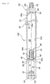
Fig. 1 is a sectional view of an inflator in the axial
direction.
Fig. 2 is a sectional view of an inflator in the axial
direction.
Fig. 3 is a sectional view of an inflator in the axial
direction.
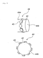
Fig. 4 is a perspective view and a plan view of a cap used
in an inflator.
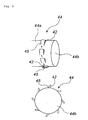
Fig. 5 is a perspective view and a plan view of a cap used
in an inflator.
Fig. 6 is a perspective view of a cap used in an inflator.
Fig. 7 is a sectional view of an inflator in the axial
direction.
Fig. 8 is a sectional view of an inflator in the axial
direction.
Fig. 9 is a sectional view of an inflator in the axial
direction.
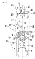
Fig. 10 is a sectional view of an inflator in the axial
direction.
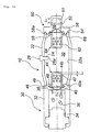
Fig. 11 is a sectional view of an inflator in the axial
direction.
Fig. 12 is a sectional view of an inflator in the axial
direction.
Fig. 13 is a sectional view of an inflator in the axial
direction.
Fig. 14 is a sectional view of an inflator in the axial
direction.
Fig. 15 is a sectional view of an inflator in the axial
direction.
Fig. 16 is a sectional view of an inflator in the axial
direction.
Fig. 17 is a sectional view of an inflator in the axial
direction.
Fig. 18 is a sectional view of an inflator in the axial
direction.
Fig. 19 is a sectional view of an inflator in the axial
direction.
Fig. 20 is a sectional view of an inflator in the axial
direction.
Fig. 21 is a sectional view of an inflator in the axial
direction.
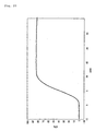
Fig. 22 is a tank curve obtained in a 60-liters tank
combustion test conducted in Example 1.
Reference numerals in the drawings will be explained.
Embodiment of Invention (I)
Embodiment 1
One embodiment will be explained with reference to Fig.
1. Fig. 1 is a sectional view of an inflator in the axial
direction thereof.
An inflator 10 comprises a pressurized medium chamber 20,
a gas generator 30 and a diffuser portion 50.
The pressurized medium chamber 20 has an outer shell
formed by a cylindrical pressurized medium chamber housing 22
and it is charged with a pressurized medium comprising a mixture
of argon and helium. Since the pressurized medium chamber
housing 22 is made symmetrical in the axial direction and a
radial direction thereof, it is unnecessary to adjust the
orientation in the axial and radial directions at a time of
assembling.
A charging hole 24 of a pressurized medium is formed on
a side surface of the pressurized medium chamber housing 22,
and it is closed by a pin 26 after the pressurized medium is
charged. A distal end portion 26a of the pin 26 protrudes into
the pressurized medium chamber 20, and the protruding portion
thereof has such a length that combustion gas flow of a gas
generating agent strikes against the protruding portion. By
adjusting the length of the protruding portion of the pin 26,
combustion gas can strike against the pin 26 to have combustion
residues adhered to the pin 26. In Fig. 1, the pin 26 can be
extended until the distal end portion 26a thereof abuts against
the opposite wall surface 22a.
The gas generator 30 includes an ignition means (an
electrical type igniter) 34 and a gas generating agent 36
accommodated in a gas generator housing 32, and it is connected
to one end of the pressurized medium chamber 20. The gas
generator housing 32 and the pressurized medium chamber housing
22 are connected at a connecting portion 49 by resistance-welding.
When the inflator 10 is assembled in an air bag system,
the ignition means 34 is connected to an external power source
via a connector and a lead wire.
The gas generating agent 36 can comprises, for example,
34 mass% of nitroguanidine as a fuel, 56 mass% of strontium
nitrate as an oxidizing agent, and 10 mass% of sodium
carboxymethylcellulose as a bonding agent (a discharged gas
temperature: 700 to 1630°C). A combustion residue generated
when the gas generating agent 36 of the above composition is
burnt is strontium oxide (melting point: 2430°C). For this
reason, the combustion residue is solidified to be massive
(slag-like) without being melted.
A first communication hole 38 between the pressurized
medium chamber 20 and the gas generator 30 is closed by a first
rupturable plate 40 transformed into a bowl-like shape due to
a pressure of the pressurized medium, and the interior of the
gas generator 30 is maintained in the normal pressure. The
first rupturable plate 40 is resistance-welded to the gas
generator housing 32 at a peripheral edge portion 40a.
A cap 44 having gas ejecting holes 42 is covered over the
first rupturable plate 40 from the pressurized medium chamber
20 side. The cap 44 is attached to cover the first rupturable
plate 40, so that combustion gas generated by combustion of the
gas generating agent 36 is always ejected from the gas ejecting
holes 42 via the cap 44.
The cap 44 has a flange portion 46 formed by folding an
opening peripheral edge portion outwardly, and it is fixed by
crimping a portion (a crimping portion) 48 of the gas generator
housing 32 at the flange portion 46.
A diffuser portion 50 having gas discharging holes 52 for
discharging the pressurized medium and the combustion gas is
connected to the other end side of the pressurized medium
chamber 20, and the diffuser portion 50 and the pressurized
medium chamber housing 22 is resistance-welded to each other
at a connecting portion 54. A filter made of wire mesh can be
disposed inside the diffuser portion 50 in order to arrest the
combustion residue, if required.
A second communication hole 56 between the pressurized
medium chamber 20 and the diffuser portion 50 is closed by a
second rupturable plate 58 transformed into a bowl-like shape
due to pressure of the pressurized medium, and the interior of
the diffuser portion 50 is maintained in the normal pressure.
The second rupturable plate 58 is resistance-welded to the
diffuser portion 50 at a peripheral edge portion 58a.
Next, an operation in case of the inflator 10 shown in
Fig. 1 which is incorporated to an air bag system mounted to
an automobile will be explained.
When an automobile receives the impact by a collision,
the igniter 34 is actuated and ignited by the activation-signal
outputting means to burn the gas generating agent 36, thereby
generating a high temperature combustion gas. At this time,
since the melting point of a combustion residue generated by
combustion of the gas generating agent 36 is equal to or more
than a discharging temperature of a gas generated from the gas
generating agent 36, the combustion residue can hardly melt,
being maintained solid.
Thereafter, the first rupturable plate 40 is broken by
a pressure rise inside the gas generator 30 due to the high
temperature combustion gas, and combustion gas including a
combustion residue flows into the cap 44 to be ejected from the
gas ejecting holes 42. At this time, since a temperature
difference between the pressurized medium and the combustion
gas in the pressurized medium chamber 20 is large, the
combustion gas is cooled rapidly, so that the high temperature
combustion residue is cooled and solidified and a combustion
residue also adheres to an inner wall surface of an end surface
44a of the cap 44. Further, since the combustion gas ejected
strikes against an inner wall 22a of the pressurized medium
chamber housing 22, the combustion residue adheres to an inner
wall surface and it can be hardly discharged out of the inflator
10. Incidentally, part of the remaining combustion residue
adheres to the pin 26, too.
Thereafter, since the second rupturable plate 58 is
broken by a pressure rise inside the pressurized medium chamber
20, the pressurized medium and the combustion gas are discharged
from the gas discharging holes 52 via the second communication
hole 56 to inflate an air bag.
In such a course of the operation, since the inflator 10
exhibits the above-described actions and effects (1) to (3),
the combustion residue discharged into the air bag is largely
suppressed by these mutual effects. In an actual measurement,
in case of the inflator of the structure shown in Fig. 1 in which
the cap 44 is not provided, the combustion residue discharged
outside the inflator 10 was 700 mg, but it could be reduced to
200 mg with the structure shown in Fig. 1. Further, as shown
in Fig. 2, by providing a cap 64 in the second rupturable plate
58 side, the arresting performance of the combustion residue
can be further increased. Reference numeral 62 denotes a gas
ejecting hole, reference numeral 68 denotes a flange portion,
and the cap 64 can be fixed to the diffuser portion 50 by the
flange portion 68 and the crimping portion 59.
Embodiment 2
Another embodiment will be explained with reference to
Fig. 3. Fig. 3 is a sectional view of an inflator in the axial
direction thereof. An inflator 100 shown in Fig. 3 has almost
the same structure as the inflator 10 shown in Fig. 1, and, in
Fig 3, the same reference numerals as those in Fig. 1 denote
the same parts. A difference in structure from Fig. 1 and a
difference in advantageous effect due to the difference in
structure will be explained below.
In the inflator 100 shown in Fig. 3, an inner wall surface
22a of a pressurized medium chamber housing 22 has a groove with
a depth of 0.2 mm formed continuously or discontinuously in the
circumferential direction. With this, a combustion residue in
combustion gas is caught and captured in the groove, an
advantageous effect (4) can be exhibited in addition to the
advantageous effects (1) to (3). Further, as shown in Fig. 2,
an aspect in which a cap 64 is provided can be employed.
Embodiment 3
Another embodiment will be explained with reference to
Fig. 4. Fig. 4 is a sectional view of an inflator in the axial
direction thereof. An inflator 200 shown in Fig. 4 has almost
the same structure as that of the inflator 10 shown in Fig. 1,
and, in Fig. 4, the same reference numerals as those in Fig.
1 denote the same parts. A difference in structure from Fig.
1 and a difference in advantageous effect due to the difference
in structure will be explained below.
In an inflator 200 shown in Fig. 4, gas ejecting holes
42 are provided on a side surface of a cap 44 and they are opened
to eject combustion gas towards the gas generator 30. With this,
combustion gas ejected from the gas ejecting holes 42 strikes
against a crimped portion 48 and its vicinities before it
strikes against the inner wall surface 22a of the pressurized
medium chamber housing 22, and thereby, an advantageous effect
(5) can be exhibited in addition to the advantageous effects
(1) to (3). Incidentally, when the aspect shown in Fig. 3 is
employed with respect to the inner wall surface 22a of the
pressurized medium chamber housing 22, the advantageous effect
(4) can be further exhibited. Also, as shown in Fig. 2, the
aspect in which the cap 64 is provided can be employed, and the
cap 44 of the other embodiment can be used instead of the cap
64.
Embodiment 4
Another embodiment will be explained with reference to
Fig. 5 to Fig. 7. Fig. 5 is a perspective view and a plan view
of a cap of one embodiment, Fig. 6 is a perspective view and
a plan view of a cap of another embodiment, and Fig. 7 is a
perspective view of a cap of another embodiment. A cap 44 shown
in Fig. 5 to Fig. 7 can be disposed into the inflators 10, 100
and 200 shown in Fig. 1, Fig. 3 and Fig. 4 respectively, and,
in the inflator shown in Fig. 2, the cap 64 can be in the shapes
shown in Fig. 5 to Fig. 7.
In the cap 44 shown in Fig. 5, gas ejecting holes 42 are
provided on a side surface of the cap 44a, and a member
(restricting member) 45 for circumferentially restricting an
ejecting direction of combustion gas from the gas ejecting holes
42. The restricting member 45 is formed in a L-letter shape
in plan view. Incidentally, the orientation of the restricting
member 45 may be a different direction from that in Fig. 5.
Since such restricting members 45 are provided,
combustion gas ejected from the gas ejecting hole 42 is ejected
in the direction along the circumferential surface of the cap
44 to form an eddy, so that the advantageous effect (5) can be
exhibited in addition to the advantageous effects (1) to (3).
Incidentally, when the shape shown in Fig. 3 can be employed
for the inner wall surface 22a of the pressurized medium chamber
housing 22, the advantageous effect (4) can be further
exhibited.
The cap 44 shown in Fig. 6 is provided with flat
plate-shaped restricting members 45 instead of the L-letter-shaped
restricting members 45 shown in Fig. 5, and the
same advantageous effect as those in Fig. 5 can be obtained.
The cap 44 shown in Fig. 7 is provided on its end surface
44b with gas ejecting holes 42, and members (restricting
members) 45 for circumferentially restricting an ejected
direction of combustion gas from the gas ejecting holes 42. The
restricting member 45 can be formed in the same shape as shown
in Fig. 5 or Fig. 6. An inflator using the cap 44 shown in Fig.
7 can obtain the same advantageous effects as those in Fig. 5
and Fig. 6.
Embodiment 5
Another embodiment will be explained with reference to
Fig. 8. Fig. 8 is a sectional view of an inflator in the axial
direction. An inflator 300 shown in Fig. 8 has almost the same
structure as that of the inflator 10 shown in Fig. 1, and, in
Fig.8, the same reference numerals as these in Fig. 1 denote the
same parts. A difference in structure from Fig. 1 and a
difference in advantageous effect due to the difference in
structure will be explained below.
In the inflator 300 shown in Fig. 8, a cylindrical barrier
member 310 is attached thereto. The barrier member 310 has a
closed one end integrated with a end surface of the cap 44b and
the other end opened, and it is formed such that a side wall
311 faces gas ejecting holes 42 provided on the side surface
of the cap 44a with a distance. Also, as shown in Fig. 2, the
aspect in which the cap 64 is provided can be employed, and
further, the cap 44 of the other embodiment can be employed
instead of the cap 64.
With such a barrier member 310, the combustion gas ej ected
from the gas ejecting holes 42 strikes against an inner wall
of a side wall 311 of the barrier member, and then, it moves
from the opening. Thereby, the advantageous effect (6) can be
exhibited in addition to the advantageous effects (1) to (3).
Incidentally, when the aspect shown in Fig. 3 is employed with
respect to the inner wall surface 22a of the pressurized medium
chamber housing 22, the advantageous effect (4) can be exhibited
as well.
Embodiment 6
Another embodiment will be explained with reference to
Fig. 9. Fig. 9 is a sectional view of an inflator in the axial
direction. An inflator 400 shown in Fig. 9 has almost the same
structure as that of the inflator 10 shown in Fig. 1, and, in
Fig. 9, the same reference numerals as those in Fig. 1 denote
the same parts. A difference in structure from Fig. 1 and a
difference in advantageous effect due to the difference in
structure will be explained below.
In the inflator 400 shown in Fig. 9, a disk-like barrier
member 410 is attached. The barrier member 410 is integrated
with a end surface of the cap 44b and it is extended from the
end surface of the cap 44b towards an inner wall surface 22a
of the pressurized medium chamber housing 22. Also, as shown
in Fig. 2, the aspect in which the cap 64 is provided can be
employed, and further, the cap 44 of another embodiment can be
used instead of the cap 64.
With such a barrier member 410, combustion gas ejected
from the gas ejecting holes 42 strikes against the barrier
member 410, and then, it moves from a clearance between the inner
wall surface 22a of the pressurized medium chamber housing 20
and an peripheral edge portion 411 of the barrier member.
Thereby, the advantageous effect (6) can be exhibited in
addition to the advantageous effects (1) to (3). Incidentally,
when the aspect shown in Fig. 3 is employed with respect to the
inner wall surface 22a of the pressurized medium chamber housing
22, the advantageous effect (4) can further be exhibited.
Embodiment 7
Another embodiment will be explained with reference to
Fig. 10. Fig. 10 is a sectional view of an inflator in the axial
direction. An inflator 500 shown in Fig. 10 has almost the same
structure as that of the inflator 10 shown in Fig. 1, and, in
Fig. 10, the same reference numerals as those in Fig. 1 denote
the same parts. A difference in structure in Fig. 1 and a
difference in advantageous effect due to the difference in
structure will be explained below.
In the inflator 500 shown in Fig. 10, a disk-like barrier
member 510 is attached. The barrier member 510 is integrated
with an end surface of the cap 44b, and it is extended from the
end surface of the cap 44b towards the inner wall surface 22a
of the pressurized medium chamber housing 20 so that a
peripheral edge portion 511 abuts on the inner wall surface 22a.
Gas passing ports 512 and restricting means 513 having similar
shapes like those in Fig. 6 are provided in the peripheral edge
portion 511. Also, as shown in Fig. 2, the aspect in which the
cap 64 is provided can be employed and further, the cap 44 of
another embodiment can be used instead of the cap 64.
With such a barrier member 510, combustion gas ejected
from the gas ejecting holes 42 strikes against the barrier
member 510, and then, it moves through the gas passing ports
512 and the restricting means 513. Thereby, the advantageous
effects (6) and (5) can be exhibited in addition to the
advantageous effects (1) to (3). Incidentally, when the aspect
shown in Fig. 3 is employed with respect to the inner wall surface
22a of the pressurized medium chamber housing 22, the
advantageous effect (4) can further be exhibited.
The inflator of the present invention can be applied to
various inflators such as an air bag inflator for a driver side,
an air bag inflator for a passenger side next to a driver, an
air bag inflator for a side collision, an inflator for a curtain
air bag, an inflator for a knee-bolster, an inflator for an
inflatable seat belt, an inflator for a tubular system, an
iflator for a pretensioner and the like.
Embodiments of Invention (II)
(1) Embodiment 1
One embodiment will be explained with reference to Fig.
11. Fig. 1 is a sectional view of an inflator in the axial
direction.
An inflator 610 comprises a pressurized gas chamber 620,
a gas generator 630 and a diffuser portion 650.
The pressurized gas chamber 620 has an outer shell formed
by a cylindrical pressurized gas chamber housing 622 and it is
charged with pressurized gas comprising a mixture of argon and
helium. Since the pressurized gas chamber housing 622 is made
symmetrical in the axial direction and a radial direction
thereof, it is unnecessary to adjust the orientation in the
axial and radial directions at a time of assembling.
A charging hole 624 of pressurized gas is formed on a side
surface of the pressurized gas chamber housing 622, and it is
closed by a pin 626 after the pressurized gas is charged. A
distal end portion 626a of the pin 626 protrudes into the
pressurized gas chamber 620, and the protruding portion thereof
has such a length that combustion gas flow of a gas generating
agent strikes against the protruding portion. By adjusting the
length of the protruding portion of the pin 626, combustion gas
can strike against the pin 26 to have combustion residues
adhered to the pin 626. In Fig. 11, the pin 626 can be extended
until the distal end portion 626a thereof abuts against the
opposite wall surface 622a.
The gas generator 630 has an ignition means (an electrical
type igniter) 634 accommodated in a gas generator housing 632
and a gas generating chamber 635 accommodating a gas generating
agent 636, and it is connected to one end of the pressurized
gas chamber 620. A retainer 639 is disposed inside the gas
generating chamber 635.
The gas generator housing 632 and the pressurized gas
chamber housing 622 are connected at a connecting portion 649
by resistance-welding. When the inflator 600 is assembled in
an air bag system, the ignition means 634 is connected to an
external power source via a connector and a lead wire.
The gas generating agent 636 can comprises, for example,
34 mass% of nitroguanidine as a fuel, 56 mass% of strontium
nitrate as an oxidizing agent, and 10 mass% of sodium
carboxymethylcellulose as a bonding agent (a discharged gas
temperature: 700 to 1630°C). A combustion residue generated
when the gas generating agent 636 of the above composition is
burnt is strontium oxide (melting point: 2430°C). For this
reason, the combustion residue is solidified to be massive
(slag-like) without being melted.
A first communication hole 638 between the pressurized
gas chamber 620 and the gas generator 630 is closed by a first
rupturable plate 640, and the interior of the gas generator 630
is maintained in the normal pressure. The first rupturable
plate 640 is resistance-welded to the gas generator housing 632
at a peripheral edge portion.
A diffuser portion 650 having gas discharging ports 652
for discharging the pressurized gas and the combustion gas is
connected to the other end side of the pressurized gas chamber
620, and the diffuser portion 650 and the pressurized gas
chamber housing 622 are resistance-welded to each other at a
connecting portion 654. The diffuser portion 650 and the gas
generating chamber housing 622 are connected such that their
central axes coincide with each other.
The diffuser portion 650 is a cap-shaped one having a
plurality of gas discharging ports 652 through which a gas
passes, wherein a distance L between a closed end surface 651
and an gas discharging port nearest to the closed end surface
651 and a diameter D of the rupturable plate 658 (except for
a welded peripheral edge portion) satisfy the following
formula: L ≥ D/2.
The distance L is preferably 3 to 8 mm, more preferably
4 to 8 mm, and particularly preferably 5 to 8 mm. The diameter
of a plurality of the gas discharging ports 652 is preferably
0.5 to 2 mm, and more preferably 0.5 to 1.2 mm. The total opening
area of a plurality of the gas discharging ports 652 is
preferably 20 to 1000 mm2, and more preferably 100 to 500 mm2.
A second communication hole 656 between the pressurized
gas chamber 620 and the diffuser portion 650 is closed by a second
rupturable plate 658, and the interior of the diffuser portion
650 is maintained in the normal pressure. The second rupturable
plate 658 is resistance-welded to the diffuser portion 650 at
its peripheral edge portion.
Next, an operation in case of the inflator 600 shown in
Fig. 11 which is incorporated to an air bag system mounted to
an automobile will be explained.
When an automobile receives the impact by a collision,
the igniter 634 is actuated and ignited by the activation-signal
outputting means to burn the gas generating agent 636, thereby
generating a high temperature combustion gas. At this time,
since the melting point of a combustion residue generated by
combustion of the gas generating agent 636 is equal to or more
than a discharging temperature of a gas generated from the gas
generating agent 636, the combustion residue can hardly melt,
being maintained solid.
Thereafter, the first rupturable plate 640 is broken by
a pressure rise inside the gas generator 630 due to the high
temperature combustion gas, and combustion gas including a
combustion residue flows into the pressurized gas chamber 620.
At this time, since a temperature difference between the
pressurized gas and the combustion gas in the pressurized gas
chamber 620 is large, the combustion gas is cooled rapidly, so
that the high temperature combustion residue is cooled and
solidified. And, since the combustion gas also strikes against
an inner wall 622a of the pressurized gas chamber housing 622,
the combustion residue adheres to an inner wall surface thereof
and it can be hardly discharged out of the inflator 600.
Incidentally, part of the remaining combustion residue adheres
to the pin 626, too.
Thereafter, since the second rupturable plate 658 is
broken by a pressure rise inside the pressurized gas chamber
620, the pressurized gas and the combustion gas are discharged
from the gas discharging holes 652 via the second communication
hole 656 to inflate an air bag.
At this time, since the combustion gas and the pressurized
gas flow out from the gas discharging ports 652 after they once
strikes against the closed end surface 651 of the diffuser
portion 650 to change their flow directions, foreign materials
can easily remain in a pocket portion from the closed end surface
651 to the gas discharging hole 652 nearest therefrom. And,
since the above action is elevated by setting a depth (L) of
the pocket portion to the maximum length (D/2) of the foreign
material or more, the foreign material can remain more easily.
Due to that the gas is discharged via the diffuser portion 650
in this manner, the foreign materials are removed.
In such a course of the operation, since the inflator 600
exhibits the above-described advantageous effects (IIa) to
(IIc), (1) to (3), an amount of pieces of the broken rupturable
plate or combustion residues discharged into the air bag is
largely suppressed by these mutual effects.
(2) Embodiment 2
One embodiment will be explained with reference to Fig.
12. Fig. 12 is a sectional view of an inflator in the axial
direction. Since the inflators shown in Fig. 12 and Fig. 11
are different from each other only in part of a structure of
a diffuser portion, the same parts are attached with the same
reference numerals and explanations thereof will be omitted.
An inflator 700 shown in Fig. 12 is provided at a distal
end portion of a diffuser portion 650 with a stud bolt 660 used
at the time of mounting the inflator to a module case.
The inflator 700 shown in Fig. 12 discharges a gas
according to the same action as that of the inflator 600 shown
in Fig. 11 and conducts the same operation.
(3) Embodiment 3
One embodiment will be explained with reference to Fig.
13. Fig. 13 is a sectional view of an inflator in the axial
direction thereof.
An inflator 10 comprises a pressurized gas chamber 20,
a gas generator 30 and a diffuser portion 50.
The pressurized gas chamber 20 has an outer shell formed
by a cylindrical pressurized gas chamber housing 22 and it is
charged with pressurized,gas comprising a mixture of argon and
helium. Since the pressurized gas chamber housing 22 is made
symmetrical in the axial direction and a radial direction
thereof, it is unnecessary to adjust the orientation in the
axial and radial directions at a time of assembling.
A charging hole 24 of pressurized gas is formed on a side
surface of the pressurized gas chamber housing 22, and it is
closed by a pin 26 after the pressurized gas is charged. A
distal end portion 26a of the pin 26 protrudes into the
pressurized gas chamber 20, and the protruding portion thereof
has such a length that combustion gas flow of a gas generating
agent strikes against the protruding portion. By adjusting the
length of the protruding portion of the pin 26, combustion gas
can strike against the pin 26 to have combustion residues
adhered to the pin 26. In Fig. 11, the pin 26 can be extended
until the distal end portion 26a thereof abuts against the
opposite wall surface 22a.
The gas generator 30 includes an ignition means (an
electrical type igniter) 34 and a gas generating agent 36
accommodated in a gas generator housing 32, and it is connected
to one end of the pressurized gas chamber 20. The gas generator
housing 32 and the pressurized gas chamber housing 22 are
connected at a connecting portion 49 by resistance-welding.
When the inflator 10 is assembled in an air bag system, the
ignition means 34 is connected to an external power source via
a connector and a lead wire.
The gas generating agent 36 can comprises, for example,
34 mass% of nitroguanidine as a fuel, 56 mass% of strontium
nitrate as an oxidizing agent, and 10 mass% of sodium
carboxymethylcellulose as a bonding agent (a discharged gas
temperature: 700 to 1630°C). A combustion residue generated
when the gas generating agent 36 of the above composition is
burnt is strontium oxide (melting point: 2430°C). For this
reason, the combustion residue is solidified to be massive
(slag-like) without being melted.
A first communication hole 38 between the pressurized gas
chamber 20 and the gas generator 30 is closed by a first
rupturable plate 40 in a bowl-like shape, and the interior of
the gas generator 30 is maintained in the normal pressure. The
first rupturable plate 40 is resistance-welded to the gas
generator housing 32 at a peripheral edge portion 40a.
A cap 44 having gas ejecting holes 42 is covered over the
first rupturable plate 40 from the pressurized gas chamber 20
side. The cap 44 is attached to cover the first rupturable plate
40, so that combustion gas generated by combustion of the gas
generating agent 36 is always ejected from the gas ejecting
holes 42 via the cap 44.
A distance L1 between a closed end surface 44b of the cap
44 and an gas ejecting hole 42 nearest to the closed end surface
44b and a diameter D1 of the rupturable plate 40 (except for
a welded peripheral edge portion) satisfy the following
formula: L1 ≥ D1/2.
The distance L1 is preferably 3 to 8 mm, more preferably
4 to 8 mm, and particularly preferably 5 to 8 mm. The diameter
of a plurality of the gas ejecting holes 42 is preferably 0.5
to 2 mm, and more preferably 0.5 to 1.2 mm. The total opening
area of a plurality of the gas ejecting holes 42 is preferably
20 to 1000 mm2, and more preferably 100 to 500 mm2.
The cap 44 has a flange portion 46 formed by folding an
opening peripheral edge portion outwardly, and it is fixed by
crimping a portion (a crimping portion) 48 of the gas generator
housing 32 at the flange portion 46.
A diffuser portion 50 having gas discharging holes 52 for
discharging the pressurized gas and the combustion gas is
connected to the other end side of the pressurized gas chamber
20, and the diffuser portion 50 and the pressurized gas chamber
housing 22 is resistance-welded to each other at a connecting
portion 54.
The diffuser portion 50 is a cap-shaped one having a
plurality of gas discharging ports 52 through which a gas passes,
wherein a distance L2 between a closed end surface 51 and an
gas discharging port nearest to the closed end surface 51 and
a diameter D2 of the rupturable plate 58 (except for a welded
peripheral edge portion) satisfy the following formula: L2 ≥
D2/2.
The distance L2 is preferably 3 to 8 mm, more preferably
4 to 8 mm, and particularly preferably 5 to 8 mm. The diameter
of a plurality of the gas discharging ports 52 is preferably
0. 5 to 2 mm, and more preferably 0. 5 to 1.2 mm. The total opening
area of a plurality of the gas discharging ports 52 is preferably
20 to 1000 mm2, and more preferably 100 to 500 mm2.
A second communication hole 56 between the pressurized
gas chamber 20 and the diffuser portion 50 is closed by a second
rupturable plate 58, and the interior of the diffuser portion
50 is maintained in the normal pressure. The second rupturable
plate 58 is resistance-welded to the diffuser portion 50 at a
peripheral edge portion 58a.
Next, an operation in case of the inflator 10 shown in
Fig. 13 which is incorporated to an air bag system mounted to
an automobile will be explained.
When an automobile receives the impact by a collision,
the igniter 34 is actuated and ignited by the activation-signal
outputting means to burn the gas generating agent 36, thereby
generating a high temperature combustion gas. At this time,
since the melting point of a combustion residue generated by
combustion of the gas generating agent 36 is equal to or more
than a discharging temperature of a gas generated from the gas
generating agent 36, the combustion residue can hardly melt,
being maintained solid.
Thereafter, the first rupturable plate 40 is broken by
a pressure rise inside the gas generator 30 due to the high
temperature combustion gas, and combustion gas including a
combustion residue flows into the cap 44 to be ejected from the
gas ejecting holes 42.
At this time, the pressurized gas flows out from the gas
ejecting holes 42 after the pressurized gas strikes against the
closed end surface 44b of the cap 44 to change its flow direction,
so that foreign materials can easily remain at a pocket portion
from the closed end surface 44b to the gas ejecting hole 42
nearest to the closed end surface 44b. And, since the
above-described action is enhanced by setting the depth (L1)
of the pocket portion to the maximum length (D1/2) of the foreign
material or more, the foreign materials can remain more easily
in the pocket. As described above, the gas is discharged from
the cap 44 to remove the foreign materials.
Further, since a temperature difference between the
pressurized gas and the combustion gas in the pressurized gas
chamber 20 is large, the combustion gas is cooled rapidly, so
that the high temperature combustion residue is cooled and
solidified and a combustion residue also adheres to the closed
end surface 44b of the cap 44. Further, the ejected combustion
gas strikes against an inner wall 22a of the pressurized gas
chamber housing 22, so that the combustion residue adheres to
an inner wall surface and it can be hardly discharged out of
the inflator 10. Incidentally, part of the remaining
combustion residue adheres to the pin 26, too.
Thereafter, the second rupturable plate 58 is broken by
a pressure rise inside the pressurized gas chamber 20, and
consequently, the pressurized gas and the combustion gas are
discharged from the gas discharging holes 52 via the second
communication hole 56 to inflate an air bag. At this time, since
the relationship of L2 ≥ D2/2 is satisfied even in the diffuser
portion 50, an action similar to that of the cap 44 can be
conducted.
In such a course of action, the inflator 10 exhibits the
above-described advantageous effects (IIa) to (IIc), (1) to (3),
an amount of pieces of the rupturable plate or combustion
residues discharged in the air bag is largely suppressed. In
an actual measurement, when the cap 44 was not provided in the
structure shown in Fig. 13 and the relationship of L2 ≥ D2/2
was not satisfied in the diffuser portion 50, combustion
residues discharged outside the inflator 10 was 700 mg. However,
it was reduced to 200 mg by employing the structure shown in
Fig. 13.
(4) Embodiment 4
One embodiment will be explained with reference to Fig.
14. Fig. 14 is a sectional view of an inflator in the axial
direction. Since the inflators shown in Fig. 14 and Fig. 13
have the same structure except that the inflator shown in Fig.
14 is further provided with a cap covering the second rupturable
plate, so that the same elements are attached with the same
reference numerals and explanations thereof will be omitted.
A cap 64 having a gas outflow holes 62 covers a second
rupturable plate 58 from the pressurized gas chamber 20 side.
The cap 64 is attached to cover the second rupturable plate 58
so that combustion gas generated by combustion of a gas
generating agent 36 always passes the cap 64 and flows into a
diffuser portion 50 from the gas outflow holes 62. Reference
numeral 62 denotes the gas outflow hole, reference numeral 68
denotes a flange portion, and the cap 64 is fixed to the diffuser
portion 50 by the flange portion 68 and crimping portion 59.
The diameter of and the total opening area of a plurality of
the gas outflow holes 62 can be made equal to those in the gas
ejecting holes 42.
In the inflator 10 shown in Fig. 14, the cap 44 and the
diffuser portion 50 satisfy the relation of L1 ≥ D1/2 and the
relation of L2 ≥ D2/2 like the inflator 10 shown in Fig. 13 and
the cap 64 is further provided, so that the advantageous effects
(IIa) to (IIc) are further enhanced.
(5) Embodiment 5
Another embodiment will be explained with reference to
Fig. 15. Fig. 15 is a sectional view of an inflator in the axial
direction. An inflator 100 shown in Fig. 15 has almost the same
structure as that of the inflator 10 shown in Fig. 13, and the
same reference numerals as those in Fig. 13 denote the same parts
in Fig. 15. A difference in structure from Fig. 13 and an
advantageous effect due to the difference in structure will be
explained below.
In the inflator 100 shown in Fig. 15, an inner wall surface
22a of a pressurized gas chamber housing 22 has a groove with
a depth of 0.2 mm formed continuously or discontinuously in the
circumferential direction. For this reason, combustion
residues in combustion gas is arrested in the groove, and
thereby, an advantageous effect (4) can be exhibited in addition
to the advantageous effects (1) to (3). Further, as shown in
Fig. 14, an aspect in which a cap 64 is provided can be employed.
Further, the cap 44 and the diffuser portion 50 satisfy
the relation of L1 ≥ D1/2 and the relation of L2 ≥ D2/2 like
the inflator 10 shown in Fig. 13, the advantageous effects (IIa)
to (IIc) can be obtained.
(6) Embodiment 6
Another embodiment will be explained with reference to
Fig. 16. Fig. 16 is a sectional view of an inflator in the axial
direction. An inflator 200 shown in Fig. 16 has almost the same
structure as that of the inflator 10 shown in Fig. 13, and, in
Fig. 16, the same reference numerals as those in Fig. 13 denote
the same parts. A difference in structure from Fig. 13 and an
advantageous effect due to the difference in structure will be
explained below.
In the inflator 200 shown in Fig. 16, gas ejecting holes
42 are provided on a side surface of a cap 44 and they are opened
to eject combustion gas towards the gas generator 30. For this
reason, the combustion gas ejected from the gas ejecting holes
42 strikes against a crimped portion 48 and its vicinities
before it strikes against the inner wall surface 22a of the
pressurized gas chamber housing 22, and thereby, an
advantageous effect (5) can be exhibited in addition to the
advantageous effects (1) to (3). Incidentally, when the aspect
shown in Fig. 15 is employed with respect to the inner wall
surface 22a of the pressurized gas chamber housing 22, the
advantageous effect (4) can be further exhibited. Also, as
shown in Fig. 14, the aspect in which the cap 64 is provided
can be employed, and the cap 44 of another embodiment can be
used instead of the cap 64.
Further, since the cap 44 and the diffuser portion 50
satisfy the relation of L1 ≥ D1/2 and the relation of L2 ≥ D2/2
like the inflator 10 shown in Fig. 13, the advantageous effects
(IIa) to (IIc) can be obtained.
(7) Embodiment 7
Another embodiment will be explained with reference to
Fig. 5 to Fig. 7. Fig. 5 is a perspective view and a plan view
of a cap of one embodiment, Fig. 6 is a perspective view and
a plan view of a cap of another embodiment, and Fig. 7 is a
perspective view of a cap of another embodiment. A cap 44 shown
in Fig. 5 to Fig. 7 can be disposed into the inflators
600,700,10,100 and 200 shown in Fig. 11 to Fig. 16 respectively.
In the cap 44 shown in Fig. 5, gas ejecting holes 42 are
provided on a side surface of the cap 44a, and a member
(restricting member) 45 for circumferentially restricting an
ej ecting direction of combustion gas from the gas ejecting holes
42. The restricting member 45 is formed in a L-letter shape
in plan view. Incidentally, the orientation of the restricting
member 45 may be a different direction from that in Fig. 5.
Since such restricting members 45 are provided,
combustion gas ejected from the gas ejecting hole 42 is ejected
in the direction along the circumferential surface of the cap
44 to form an eddy, so that the advantageous effect (5) can be
exhibited in addition to the advantageous effects (1) to (3).
Incidentally, when the shape shown in Fig. 15 can be employed
for the inner wall surface 22a of the pressurized gas chamber
housing 22, the advantageous effect (4) can be further
exhibited.
The cap 44 shown in Fig. 7 is provided with flat
plate-shaped restricting members 45 instead of the L-letter-shaped
restricting members 45 shown in Fig. 5, and the
same advantageous effect as those in Fig. 5 can be obtained.
The cap 44 shown in Fig. 7 is provided on its end surface
44a with gas ejecting holes 42, and members (restricting
members) 45 for circumferentially restricting an ejected
direction of combustion gas from the gas ejecting holes 42. The
restricting member 45 can be formed in the same shape as shown
in Fig. 5 or Fig. 6. An inflator using the cap 44 shown in Fig.
7 can obtain the same advantageous effects as those in Fig. 5
and Fig. 6.
By adjusting the caps 44 shown in Fig. 5 and Fig. 6 to
satisfy the relation of L1 ≥ D1/2, the advantageous effects
(IIa) to (IIc) can be obtained like the inflator 10 shown in
Fig. 13. In particular, when the caps 44 shown in Fig. 5 and
Fig. 6 are used, pieces of the broken first rupturable plate
40 can hardly be discharged out through the gas ejecting holes
42 due to an action of the restricting members, and thereby an
arresting effect is further improved.
(8) Embodiment 8
Another embodiment will be explained with reference to
Fig. 10. Fig. 10 is a sectional view of an inflator in the axial
direction. An inflator 300 shown in Fig. 10 has almost the same
structure as that of the inflator 10 shown in Fig. 13, and, in
Fig.10, the same reference numerals as these in Fig.13 denote
the same parts. A difference in structure from Fig. 13 and a
difference in advantageous effect due to the difference in
structure will be explained below.
In the inflator 300 shown in Fig. 10, a cylindrical
barrier member 310 is attached thereto. The barrier member 310
has a closed one end integrated with a end surface of the cap
44b and the other end opened, and it is formed such that a side
wall 311 faces gas ejecting holes 42 provided on the side surface
of the cap 44a with a distance. Also, as shown in Fig. 14, the
aspect in which the cap 64 is provided can be employed, and
further, the cap 44 of the other embodiment can be employed
instead of the cap 64.
Since the cap 44 and the diffuser portion 50 satisfy the
relation of L1 ≥ D1/2 and the relation of L2 ≥ D2/2 like the
inflator 10 shown in Fig. 13, the advantageous effects (IIa)
to (IIc) can be obtained.
Further, because of a barrier member 310 provided with
the cap 44, the combustion gas ejected from the gas ejecting
holes 42 strikes against an inner wall of a side wall 311 of
the barrier member, and then, it moves from the opening.
Thereby, the advantageous effect (6) can be exhibited in
addition to the advantageous effects (1) to (3). Incidentally,
when the aspect shown in Fig. 15 is employed with respect to
the inner wall surface 22a of the pressurized gas chamber
housing 22, the advantageous effect (4) can be exhibited as
well.
(9) Embodiment 9
Another embodiment will be explained with reference to
Fig. 11. Fig. 11 is a sectional view of an inflator in the axial
direction. An inflator 400 shown in Fig. 11 has almost the same
structure as that of the inflator 10 shown in Fig. 13, and, in
Fig. 11, the same reference numerals as those in Fig. 13 denote
the same parts. A difference in structure from Fig. 13 and a
difference in advantageous effect due to the difference in
structure will be explained below.
In the inflator 400 shown in Fig. 11, a disk-like barrier
member 410 is attached. The barrier member 410 is integrated
with a end surface of the cap 44b and it is extended from the
end surface of the cap 44b towards an inner wall surface 22a
of the pressurized gas chamber housing 22. Also, as shown in
Fig. 14, the aspect in which the cap 64 is provided can be
employed, and further, the cap 44 of another embodiment can be
used instead of the cap 64.
Since the cap 44 and the diffuser portion 50 satisfy the
relation of L1 ≥ D1/2 and the relation of L2 ≥ D2/2 like the
inflator 10 shown in Fig. 13, the advantageous effects (IIa)
to (IIc) can be obtained.
Further, because of a barrier member 410 attached to the
cap 44, combustion gas ejected from the gas ejecting holes 42
strikes against the barrier member 410, and then, it moves from
a clearance between the inner wall surface 22a of the
pressurized gas chamber housing 20 and an peripheral edge
portion 411 of the barrier member. Thereby, the advantageous
effect (6) can be exhibited in addition to the advantageous
effects (1) to (3) . Incidentally, when the aspect shown in Fig.
15 is employed with respect to the inner wall surface 22a of
the pressurized gas chamber housing 22, the advantageous effect
(4) can further be exhibited.
(10) Embodiment 10
Another embodiment will be explained with reference to
Fig. 12. Fig. 12 is a sectional view of an inflator in the axial
direction. An inflator 500 shown in Fig. 12 has almost the same
structure as that of the inflator 10 shown in Fig. 13, and, in
Fig. 12, the same reference numerals as those in Fig. 13 denote
the same parts. A difference in structure in Fig. 13 and a
difference in advantageous effect due to the difference in
structure will be explained below.
In the inflator 500 shown in Fig. 12, a disk-like barrier
member 510 is attached. The barrier member 510 is integrated
with an end surface of the cap 44b, and it is extended from the
end surface of the cap 44b towards the inner wall surface 22a
of the pressurized gas chamber housing 20 so that a peripheral
edge portion 511 abuts on the inner wall surface 22a. Gas
passing ports 512 and restricting means 513 having similar
shapes like those in Fig. 8 are provided in the peripheral edge
portion 511. Also, as shown in Fig. 14, the aspect in which
the cap 64 is provided can be employed and further, the cap 44
of another embodiment can be used instead of the cap 64.
Since the cap 44 and the diffuser portion 50 satisfy the
relation of L1 ≥ D1/2 and the relation of L2 ≥ D2/2 like the
inflator 10 shown in Fig. 13, the advantageous effects (IIa)
to (IIc) can be obtained.
Further, because of a barrier member 510 attached to the
cap 44, combustion gas ejected from the gas ejecting holes 42
strikes against the barrier member 510, and then, it moves
through the gas passing ports 512 and the restricting means 513.
Thereby, the advantageous effects (6) and (5) can be exhibited
in addition to the advantageous effects (1) to (3).
Incidentally, when the aspect shown in Fig. 14 is employed with
respect to the inner wall surface 22a of the pressurized gas
chamber housing 22, the advantageous effect (4) can further be
exhibited.
The inflator of the present invention can be applied to
various inflators such as an air bag inflator for a driver side,
an air bag inflator for a passenger side next to a driver, an
air bag inflator for a side collision, an inflator for a curtain
air bag, an inflator for a knee-bolster, an inflator for an
inflatable seat belt, an inflator for a tubular system, an
iflator for a pretensioner and the like.
Embodiments of the Invention (III)
Inflators of the present invention will be explained with
reference to Fig. 20 and Fig. 21. Fig. 20 and Fig. 21 are cross
sectional views of embodiments of the present invention. An
inflator 10 shown in Fig. 20 and an inflator 100 shown in Fig.
21 have almost the same structure except that the axial size
of the inflator 10 is shorter than that of the inflator 100 and
these inflators are different from each other in structure of
a diffuser portion.
The inflator 10 comprises a pressurized gas chamber 20,
a gas generator 30 and a diffuser 50, and outer diameters of
these members are set to approximately the same.
The pressurized gas chamber 20 has an outer shell formed
by a cylindrical pressurized gas chamber housing 22 and it is
charged with pressurized gas comprising a mixture of argon and
helium, not including oxygen gas.
The pressurized gas chamber housing 22 is symmetrical
axially and radially, and outer diameters at both ends are
reduced to about 22 mm relative to an outer diameter D (about
25 mm) at the central portion thereof. Since a length L of the
pressurized gas housing 22 is set to about 50 to 250 mm, L/D
is 1 to 10.
Since the pressurized gas chamber housing 22 has such a
shape, it is unnecessary to adjust the orientation of the
pressurized gas chamber housing in the axial and radial
directions at a time of assembling, and joining work of the gas
generator 30 and the diffuser portion 50 effected by
resistance-welding or the like can be facilitated.
A charging hole 24 for pressurized gas is formed on a side
surface of the pressurized gas chamber housing 22, and it is
closed by a pin 26 after pressurized gas is charged. A distal
end portion 26a of the pin 26 protrudes into the pressurized
medium chamber 20, and the protruding portion thereof has such
a length that combustion gas flow of a gas generating agent
strikes against the protruding portion. By adjusting the
length of the protruding portion of the pin 26, combustion gas
can strike against the pin 26 to have combustion residues
adhered to the pin 26. In Fig. 20, the pin 26 can be extended
until the distal end portion 26a thereof abuts against the
opposite wall surface 22a.
The gas generator 30 includes an ignition means (an
electrical type igniter) 34 and a gas generating agent 36
accommodated in a gas generator housing 32, and it is connected
to one end of the pressurized gas chamber 20. The inflator 10
is fixed by crimping the part 35 of the gas generator housing
35.
The gas generator housing 32 and the pressurized gas
chamber housing 22 are connected at a connecting portion 49 by
resistance-welding. When the inflator 10 is assembled in an
air bag system, the ignition means 34 is connected to an external
power source via a connector and a lead wire.
A first communication hole 38 between the pressurized gas
chamber 20 and the gas generator 30 is closed by a first
rupturable plate 40 transformed into a bowl-like shape due to
a pressure of the pressurized gas, and the interior of the gas
generator 30 is maintained in the normal pressure. The first
rupturable plate 40 is resistance-welded to the gas generator
housing 32 at a peripheral edge portion 40a.
A cap 44 having gas ejecting holes 42 is covered over the
first rupturable plate 40 from the pressurized gas chamber 20
side. The cap 44 is attached to cover the first rupturable plate
40, so that combustion gas generated by combustion of the gas
generating agent 36 is always ejected from the gas ejecting
holes 42 via the cap 44.
The cap 44 has a flange portion 46 formed by folding an
opening peripheral edge portion outwardly, and it is fixed by
crimping a portion (a crimping portion) 48 of the gas generator
housing 32 at the flange portion 46.
A diffuser portion 50 having gas discharging holes 52 for
discharging the pressurized gas and the combustion gas is
connected to the other end side of the pressurized gas chamber
20, and the diffuser portion 50 and the pressurized gas chamber
housing 22 is resistance-welded to each other at a connecting
portion 54. A filter made of wire mesh can be disposed inside
the diffuser portion 50 in order to arrest the combustion
residue, if required.
A second communication hole 56 between the pressurized
gas chamber 20 and the diffuser portion 50 is closed by a second
rupturable plate 58 transformed into a bowl-like shape due to
pressure of the pressurized gas, and the interior of the
diffuser portion 50 is maintained in the normal pressure. The
second rupturable plate 58 is resistance-welded to the diffuser
portion 50 at a peripheral edge portion 58a.
The detail of requirements (1) to (8) in an inflator 10
shown in Fig. 20 is as follows:
Requirements (1) and (6)
Pressurized gas comprising a mixture of argon and helium,
but not including oxygen gas is charged in a gas generator 20
under a charging pressure of 30,000 to 67,000 kPa.
Requirements (2) and (5)
As a gas generating agent 36, one with a cylindrical shape
comprising nitroguanidine/strontium nitrate/sodium
carboxymethylcellulose/acid clay = 34.3/49.6/9.4/6.7 (mass%)
(pressure index = 0.6, combustion flame temperature = 2098°C)
is used in the amount of 1.9 to 5.3 g.
Requirement (3)
A ratio of an amount (mole number) of pressurized gas (A1)
and an amount (mole number) of a gas generated by combustion
of a gas generating agent (A2), A1/A2 = 1 to 20;
Requirement (4)
A ratio of a mass of pressurized gas (B1) and a mass of
a gas generating agent (B2), B1/B2 = 1 to 20;
Requirement (7)
A ratio of an amount (mole number) of pressurized gas (A1)
and a total surface opening (cm2) of a gas generating agent (C),
A1/C = 0.004 to 0.05 mole/cm2;
Requirement (8)
A ratio of a total surface area (cm2) of a gas generating
agent (C) and a total area (cm2) of gas discharging holes (D),
C/D is 0.5 to 4;
Next, an operation of the inflator 10 shown in Fig. 20
which is assembled in an air bag system mounted on an automobile
will be explained.
When an automobile receives the impact by collision, the
igniter 34 is activated and ignited upon receiving an actuation
signal from a control unit to burn the gas generating agent 36,
and thereby, combustion gas with a high temperature is
generated.
Thereafter, the first rupturable plate 40 is broken by
a pressure rise inside the gas generator 30 due to the high
temperature combustion gas, and combustion gas including a
combustion residue flows into the cap 44 to be ejected from the
gas ejecting holes 42. At this time, since a temperature
difference between the pressurized gas and the combustion gas
in the pressurized gas chamber 20 is large, the combustion gas
is cooled rapidly, so that the high temperature combustion
residue is cooled and solidified and a combustion residue also
adheres to an inner wall surface of an end surface 44a of the
cap 44. Further, since the combustion gas ejected strikes
against an inner wall 22a of the pressurized gas chamber housing
22, the combustion residue adheres to an inner wall surface and
it can be hardly discharged out of the inflator 10.
Incidentally, part of the remaining combustion residue adheres
to the pin 26, too.
Thereafter, since the second rupturable plate 58 is
broken by a pressure rise inside the pressurized gas chamber
20, the pressurized gas and the combustion gas are discharged
from the gas discharging holes 52 via the second communication
hole 56 to inflate an air bag.
In such a course of action, since the inflator 10 is
provided with the above-described requirements (1) to (6), or
preferably (1) to (8), the internal pressure in the inflator
is controlled not to rise excessively when the gas generating
agent is burnt, even with the high pressurized-gas charging
pressure of 30,000 to 67, 000 kPa. As a result, the air bag can
be inflated within an optimal time for protecting an occupant
(generally, which is considered to be 10 to 30 msec).
Further, an internal pressure of the inflator when the
gas generating agent is burnt can be controlled suitably, and
thereby, the size of the inflator can be made small to downsize
of the inflator while the charged amount of the pressurized gas
is maintained to be equal to that in the prior art, that is,
an amount of the pressurized gas for inflating the air bag is
secured. And, as the result of downsizing the inflator, even
when the charging pressure of the pressurized gas rises, an
internal pressure of the inflator at an actuation can be
controlled suitably.
The inflators of the present invention can be applied to
various inflators such as an air bag inflator for a driver side,
an air bag inflator for a passenger side next to a driver, an
air bag inflator for a side collision, an inflator for a curtain
air bag, an inflator for a knee-bolster, an inflator for an
inflatable seat belt, an inflator for a tubular system, an
inflator for a pretensioner and the like.
Examples
The present invention will be explained in detail as
follows on the basis of Examples, but the present invention is
not limited to these Examples.
Example 1
An inflator having the structure shown in Fig. 20 was
produced. An entire length of the inflator was 110 mm, a length
(L) of a pressurized gas chamber housing is 60 mm, an outer
diameter (D) thereof is 25 mm, an thickness thereof is 2 mm
(material: seamless steel pipe), and outer diameters of the
other portions of the inflator were almost the same. The detail
of the requirements (1) to (8) and the like are as follows:
A well known 60 L tank combustion test, for example, as
described in a paragraph 11 of JP-B No. 2963086, was conducted
with this inflator. A tank curve is shown in Fig. 22.
As apparent from the tank curve shown in Fig. 22, even
when the inflator itself was downsized and an internal pressure
of the inflator was high before actuation, an internal pressure
of the inflator at an actuation time was controlled by
satisfying the requirements (1) to (8). As a result, it was
confirmed that the air bag was inflated maximally at about 10
msec and that the inflator was normally actuated.
Example 2
An inflator having the structure shown in Fig. 21 was
produced. An entire length of the inflator was 280 mm, a length
(L) of a pressurized gas chamber housing is 200 mm, an outer
diameter (D) thereof is 25 mm, an thickness thereof is 2 mm
(material: seamless steel pipe), and outer diameters of the
other portions of the inflator were almost the same. The detail
of the requirements (1) to (8) and the like are as follows:
The same 60-liter tank combustion test was conducted with
this inflator as in Example 1, and a tank curve generally equal
to that in Fig. 22 was obtained.
Incidentally, when compared with the fact that, in the
paragraph 136 of in JP-A 9-76870 described as the prior art,
there is a description that an interior of an inflator housing
is maintained in a high pressure such as 4000 psi (27,600 kPa)
or so, an internal pressure of the inflator of Example 1 at a
time of actuation is expected to be much higher than that in
the prior art. However, since the requirements (1) to (8) were
provided, an internal pressure of the inflator was controlled
so that the inflator was normally operated.