EP1449699A1 - Compound power drive system including dynamo-electric units - Google Patents
Compound power drive system including dynamo-electric units Download PDFInfo
- Publication number
- EP1449699A1 EP1449699A1 EP03251041A EP03251041A EP1449699A1 EP 1449699 A1 EP1449699 A1 EP 1449699A1 EP 03251041 A EP03251041 A EP 03251041A EP 03251041 A EP03251041 A EP 03251041A EP 1449699 A1 EP1449699 A1 EP 1449699A1
- Authority
- EP
- European Patent Office
- Prior art keywords
- steering shaft
- electric unit
- dynamo
- transmission mechanism
- engine
- Prior art date
- Legal status (The legal status is an assumption and is not a legal conclusion. Google has not performed a legal analysis and makes no representation as to the accuracy of the status listed.)
- Granted
Links
Images















Classifications
-
- B—PERFORMING OPERATIONS; TRANSPORTING
- B60—VEHICLES IN GENERAL
- B60K—ARRANGEMENT OR MOUNTING OF PROPULSION UNITS OR OF TRANSMISSIONS IN VEHICLES; ARRANGEMENT OR MOUNTING OF PLURAL DIVERSE PRIME-MOVERS IN VEHICLES; AUXILIARY DRIVES FOR VEHICLES; INSTRUMENTATION OR DASHBOARDS FOR VEHICLES; ARRANGEMENTS IN CONNECTION WITH COOLING, AIR INTAKE, GAS EXHAUST OR FUEL SUPPLY OF PROPULSION UNITS IN VEHICLES
- B60K6/00—Arrangement or mounting of plural diverse prime-movers for mutual or common propulsion, e.g. hybrid propulsion systems comprising electric motors and internal combustion engines
- B60K6/20—Arrangement or mounting of plural diverse prime-movers for mutual or common propulsion, e.g. hybrid propulsion systems comprising electric motors and internal combustion engines the prime-movers consisting of electric motors and internal combustion engines, e.g. HEVs
- B60K6/22—Arrangement or mounting of plural diverse prime-movers for mutual or common propulsion, e.g. hybrid propulsion systems comprising electric motors and internal combustion engines the prime-movers consisting of electric motors and internal combustion engines, e.g. HEVs characterised by apparatus, components or means specially adapted for HEVs
- B60K6/38—Arrangement or mounting of plural diverse prime-movers for mutual or common propulsion, e.g. hybrid propulsion systems comprising electric motors and internal combustion engines the prime-movers consisting of electric motors and internal combustion engines, e.g. HEVs characterised by apparatus, components or means specially adapted for HEVs characterised by the driveline clutches
- B60K6/387—Actuated clutches, i.e. clutches engaged or disengaged by electric, hydraulic or mechanical actuating means
-
- B—PERFORMING OPERATIONS; TRANSPORTING
- B60—VEHICLES IN GENERAL
- B60W—CONJOINT CONTROL OF VEHICLE SUB-UNITS OF DIFFERENT TYPE OR DIFFERENT FUNCTION; CONTROL SYSTEMS SPECIALLY ADAPTED FOR HYBRID VEHICLES; ROAD VEHICLE DRIVE CONTROL SYSTEMS FOR PURPOSES NOT RELATED TO THE CONTROL OF A PARTICULAR SUB-UNIT
- B60W20/00—Control systems specially adapted for hybrid vehicles
- B60W20/40—Controlling the engagement or disengagement of prime movers, e.g. for transition between prime movers
-
- B—PERFORMING OPERATIONS; TRANSPORTING
- B60—VEHICLES IN GENERAL
- B60K—ARRANGEMENT OR MOUNTING OF PROPULSION UNITS OR OF TRANSMISSIONS IN VEHICLES; ARRANGEMENT OR MOUNTING OF PLURAL DIVERSE PRIME-MOVERS IN VEHICLES; AUXILIARY DRIVES FOR VEHICLES; INSTRUMENTATION OR DASHBOARDS FOR VEHICLES; ARRANGEMENTS IN CONNECTION WITH COOLING, AIR INTAKE, GAS EXHAUST OR FUEL SUPPLY OF PROPULSION UNITS IN VEHICLES
- B60K6/00—Arrangement or mounting of plural diverse prime-movers for mutual or common propulsion, e.g. hybrid propulsion systems comprising electric motors and internal combustion engines
- B60K6/20—Arrangement or mounting of plural diverse prime-movers for mutual or common propulsion, e.g. hybrid propulsion systems comprising electric motors and internal combustion engines the prime-movers consisting of electric motors and internal combustion engines, e.g. HEVs
- B60K6/42—Arrangement or mounting of plural diverse prime-movers for mutual or common propulsion, e.g. hybrid propulsion systems comprising electric motors and internal combustion engines the prime-movers consisting of electric motors and internal combustion engines, e.g. HEVs characterised by the architecture of the hybrid electric vehicle
- B60K6/44—Series-parallel type
- B60K6/445—Differential gearing distribution type
-
- B—PERFORMING OPERATIONS; TRANSPORTING
- B60—VEHICLES IN GENERAL
- B60L—PROPULSION OF ELECTRICALLY-PROPELLED VEHICLES; SUPPLYING ELECTRIC POWER FOR AUXILIARY EQUIPMENT OF ELECTRICALLY-PROPELLED VEHICLES; ELECTRODYNAMIC BRAKE SYSTEMS FOR VEHICLES IN GENERAL; MAGNETIC SUSPENSION OR LEVITATION FOR VEHICLES; MONITORING OPERATING VARIABLES OF ELECTRICALLY-PROPELLED VEHICLES; ELECTRIC SAFETY DEVICES FOR ELECTRICALLY-PROPELLED VEHICLES
- B60L50/00—Electric propulsion with power supplied within the vehicle
- B60L50/10—Electric propulsion with power supplied within the vehicle using propulsion power supplied by engine-driven generators, e.g. generators driven by combustion engines
- B60L50/16—Electric propulsion with power supplied within the vehicle using propulsion power supplied by engine-driven generators, e.g. generators driven by combustion engines with provision for separate direct mechanical propulsion
-
- B—PERFORMING OPERATIONS; TRANSPORTING
- B60—VEHICLES IN GENERAL
- B60L—PROPULSION OF ELECTRICALLY-PROPELLED VEHICLES; SUPPLYING ELECTRIC POWER FOR AUXILIARY EQUIPMENT OF ELECTRICALLY-PROPELLED VEHICLES; ELECTRODYNAMIC BRAKE SYSTEMS FOR VEHICLES IN GENERAL; MAGNETIC SUSPENSION OR LEVITATION FOR VEHICLES; MONITORING OPERATING VARIABLES OF ELECTRICALLY-PROPELLED VEHICLES; ELECTRIC SAFETY DEVICES FOR ELECTRICALLY-PROPELLED VEHICLES
- B60L50/00—Electric propulsion with power supplied within the vehicle
- B60L50/50—Electric propulsion with power supplied within the vehicle using propulsion power supplied by batteries or fuel cells
- B60L50/60—Electric propulsion with power supplied within the vehicle using propulsion power supplied by batteries or fuel cells using power supplied by batteries
- B60L50/61—Electric propulsion with power supplied within the vehicle using propulsion power supplied by batteries or fuel cells using power supplied by batteries by batteries charged by engine-driven generators, e.g. series hybrid electric vehicles
-
- B—PERFORMING OPERATIONS; TRANSPORTING
- B60—VEHICLES IN GENERAL
- B60W—CONJOINT CONTROL OF VEHICLE SUB-UNITS OF DIFFERENT TYPE OR DIFFERENT FUNCTION; CONTROL SYSTEMS SPECIALLY ADAPTED FOR HYBRID VEHICLES; ROAD VEHICLE DRIVE CONTROL SYSTEMS FOR PURPOSES NOT RELATED TO THE CONTROL OF A PARTICULAR SUB-UNIT
- B60W20/00—Control systems specially adapted for hybrid vehicles
- B60W20/30—Control strategies involving selection of transmission gear ratio
-
- B—PERFORMING OPERATIONS; TRANSPORTING
- B60—VEHICLES IN GENERAL
- B60K—ARRANGEMENT OR MOUNTING OF PROPULSION UNITS OR OF TRANSMISSIONS IN VEHICLES; ARRANGEMENT OR MOUNTING OF PLURAL DIVERSE PRIME-MOVERS IN VEHICLES; AUXILIARY DRIVES FOR VEHICLES; INSTRUMENTATION OR DASHBOARDS FOR VEHICLES; ARRANGEMENTS IN CONNECTION WITH COOLING, AIR INTAKE, GAS EXHAUST OR FUEL SUPPLY OF PROPULSION UNITS IN VEHICLES
- B60K1/00—Arrangement or mounting of electrical propulsion units
- B60K1/02—Arrangement or mounting of electrical propulsion units comprising more than one electric motor
-
- B—PERFORMING OPERATIONS; TRANSPORTING
- B60—VEHICLES IN GENERAL
- B60L—PROPULSION OF ELECTRICALLY-PROPELLED VEHICLES; SUPPLYING ELECTRIC POWER FOR AUXILIARY EQUIPMENT OF ELECTRICALLY-PROPELLED VEHICLES; ELECTRODYNAMIC BRAKE SYSTEMS FOR VEHICLES IN GENERAL; MAGNETIC SUSPENSION OR LEVITATION FOR VEHICLES; MONITORING OPERATING VARIABLES OF ELECTRICALLY-PROPELLED VEHICLES; ELECTRIC SAFETY DEVICES FOR ELECTRICALLY-PROPELLED VEHICLES
- B60L2240/00—Control parameters of input or output; Target parameters
- B60L2240/40—Drive Train control parameters
- B60L2240/42—Drive Train control parameters related to electric machines
- B60L2240/421—Speed
-
- B—PERFORMING OPERATIONS; TRANSPORTING
- B60—VEHICLES IN GENERAL
- B60L—PROPULSION OF ELECTRICALLY-PROPELLED VEHICLES; SUPPLYING ELECTRIC POWER FOR AUXILIARY EQUIPMENT OF ELECTRICALLY-PROPELLED VEHICLES; ELECTRODYNAMIC BRAKE SYSTEMS FOR VEHICLES IN GENERAL; MAGNETIC SUSPENSION OR LEVITATION FOR VEHICLES; MONITORING OPERATING VARIABLES OF ELECTRICALLY-PROPELLED VEHICLES; ELECTRIC SAFETY DEVICES FOR ELECTRICALLY-PROPELLED VEHICLES
- B60L2240/00—Control parameters of input or output; Target parameters
- B60L2240/40—Drive Train control parameters
- B60L2240/44—Drive Train control parameters related to combustion engines
- B60L2240/441—Speed
-
- B—PERFORMING OPERATIONS; TRANSPORTING
- B60—VEHICLES IN GENERAL
- B60L—PROPULSION OF ELECTRICALLY-PROPELLED VEHICLES; SUPPLYING ELECTRIC POWER FOR AUXILIARY EQUIPMENT OF ELECTRICALLY-PROPELLED VEHICLES; ELECTRODYNAMIC BRAKE SYSTEMS FOR VEHICLES IN GENERAL; MAGNETIC SUSPENSION OR LEVITATION FOR VEHICLES; MONITORING OPERATING VARIABLES OF ELECTRICALLY-PROPELLED VEHICLES; ELECTRIC SAFETY DEVICES FOR ELECTRICALLY-PROPELLED VEHICLES
- B60L2240/00—Control parameters of input or output; Target parameters
- B60L2240/40—Drive Train control parameters
- B60L2240/48—Drive Train control parameters related to transmissions
- B60L2240/486—Operating parameters
-
- B—PERFORMING OPERATIONS; TRANSPORTING
- B60—VEHICLES IN GENERAL
- B60L—PROPULSION OF ELECTRICALLY-PROPELLED VEHICLES; SUPPLYING ELECTRIC POWER FOR AUXILIARY EQUIPMENT OF ELECTRICALLY-PROPELLED VEHICLES; ELECTRODYNAMIC BRAKE SYSTEMS FOR VEHICLES IN GENERAL; MAGNETIC SUSPENSION OR LEVITATION FOR VEHICLES; MONITORING OPERATING VARIABLES OF ELECTRICALLY-PROPELLED VEHICLES; ELECTRIC SAFETY DEVICES FOR ELECTRICALLY-PROPELLED VEHICLES
- B60L2240/00—Control parameters of input or output; Target parameters
- B60L2240/40—Drive Train control parameters
- B60L2240/50—Drive Train control parameters related to clutches
- B60L2240/507—Operating parameters
-
- B—PERFORMING OPERATIONS; TRANSPORTING
- B60—VEHICLES IN GENERAL
- B60W—CONJOINT CONTROL OF VEHICLE SUB-UNITS OF DIFFERENT TYPE OR DIFFERENT FUNCTION; CONTROL SYSTEMS SPECIALLY ADAPTED FOR HYBRID VEHICLES; ROAD VEHICLE DRIVE CONTROL SYSTEMS FOR PURPOSES NOT RELATED TO THE CONTROL OF A PARTICULAR SUB-UNIT
- B60W20/00—Control systems specially adapted for hybrid vehicles
-
- Y—GENERAL TAGGING OF NEW TECHNOLOGICAL DEVELOPMENTS; GENERAL TAGGING OF CROSS-SECTIONAL TECHNOLOGIES SPANNING OVER SEVERAL SECTIONS OF THE IPC; TECHNICAL SUBJECTS COVERED BY FORMER USPC CROSS-REFERENCE ART COLLECTIONS [XRACs] AND DIGESTS
- Y02—TECHNOLOGIES OR APPLICATIONS FOR MITIGATION OR ADAPTATION AGAINST CLIMATE CHANGE
- Y02T—CLIMATE CHANGE MITIGATION TECHNOLOGIES RELATED TO TRANSPORTATION
- Y02T10/00—Road transport of goods or passengers
- Y02T10/60—Other road transportation technologies with climate change mitigation effect
- Y02T10/62—Hybrid vehicles
-
- Y—GENERAL TAGGING OF NEW TECHNOLOGICAL DEVELOPMENTS; GENERAL TAGGING OF CROSS-SECTIONAL TECHNOLOGIES SPANNING OVER SEVERAL SECTIONS OF THE IPC; TECHNICAL SUBJECTS COVERED BY FORMER USPC CROSS-REFERENCE ART COLLECTIONS [XRACs] AND DIGESTS
- Y02—TECHNOLOGIES OR APPLICATIONS FOR MITIGATION OR ADAPTATION AGAINST CLIMATE CHANGE
- Y02T—CLIMATE CHANGE MITIGATION TECHNOLOGIES RELATED TO TRANSPORTATION
- Y02T10/00—Road transport of goods or passengers
- Y02T10/60—Other road transportation technologies with climate change mitigation effect
- Y02T10/64—Electric machine technologies in electromobility
-
- Y—GENERAL TAGGING OF NEW TECHNOLOGICAL DEVELOPMENTS; GENERAL TAGGING OF CROSS-SECTIONAL TECHNOLOGIES SPANNING OVER SEVERAL SECTIONS OF THE IPC; TECHNICAL SUBJECTS COVERED BY FORMER USPC CROSS-REFERENCE ART COLLECTIONS [XRACs] AND DIGESTS
- Y02—TECHNOLOGIES OR APPLICATIONS FOR MITIGATION OR ADAPTATION AGAINST CLIMATE CHANGE
- Y02T—CLIMATE CHANGE MITIGATION TECHNOLOGIES RELATED TO TRANSPORTATION
- Y02T10/00—Road transport of goods or passengers
- Y02T10/60—Other road transportation technologies with climate change mitigation effect
- Y02T10/70—Energy storage systems for electromobility, e.g. batteries
-
- Y—GENERAL TAGGING OF NEW TECHNOLOGICAL DEVELOPMENTS; GENERAL TAGGING OF CROSS-SECTIONAL TECHNOLOGIES SPANNING OVER SEVERAL SECTIONS OF THE IPC; TECHNICAL SUBJECTS COVERED BY FORMER USPC CROSS-REFERENCE ART COLLECTIONS [XRACs] AND DIGESTS
- Y02—TECHNOLOGIES OR APPLICATIONS FOR MITIGATION OR ADAPTATION AGAINST CLIMATE CHANGE
- Y02T—CLIMATE CHANGE MITIGATION TECHNOLOGIES RELATED TO TRANSPORTATION
- Y02T10/00—Road transport of goods or passengers
- Y02T10/60—Other road transportation technologies with climate change mitigation effect
- Y02T10/7072—Electromobility specific charging systems or methods for batteries, ultracapacitors, supercapacitors or double-layer capacitors
Definitions
- the present invention is related to a drive dynamo-electric unit controlled compound system comprised of one dynamo-electric unit or a primary and a secondary dynamo-electric unit units or more than two dynamo-electric unit units incorporated with engine or other rotating moment device, and one unit or more than one unit of centrifugal clutch, one-way transmission mechanism or output clutch or related transmission mechanism and manual control interface, central controller and storage device to create specific control pattern and to execute the operation of specific compound power function by selection among those units and control of drive control device operation.
- the present invention by incorporating an engine to a primary dynamo-electric unit and a transmission mechanism to create new functions as supplementary to a prior art of incorporating an engine to a single dynamo-electric unit under European Patent No. 0826544 (formerly Application No. 96306388.8) invented by the same inventor of this application.
- the primary purpose of the present invention is to provide an drive dynamo-electric unit controlled compound system comprised of one dynamo-electric unit or a primary and a secondary dynamo-electric unit units or more than two dynamo-electric unit units incorporated with engine or other rotating moment device, and one unit or more than one unit of centrifugal clutch, one-way transmission mechanism or output clutch or related transmission mechanism and manual control interface, central controller and storage device to create specific control pattern and to execute the operation of specific compound power function by selection among those units and control of drive control device operation.
- the present invention related to a drive dynamo-electric unit controlled compound system including one dynamo-electric unit or a primary and a secondary dynamo-electric unit units or more than two dynamo-electric unit units incorporated with engine or other rotating moment device, and one unit or more than one unit of centrifugal clutch, one-way transmission mechanism or output clutch or related transmission mechanism and manual control interface, central controller and storage device to create specific control pattern and to execute the operation of specific compound power function by selection among those units and control of drive control device operation, is essentially comprised of the following units:
- the one-way transmission mechanism SWC101 is independently provided or provided at the same time with the centrifugal clutch FC101 for the system to indicate various compound power characteristics; as required, the relative locations between the one-way transmission mechanism SWC101 and the centrifugal clutch FC101 has the centrifugal clutch FC101 provided at where close to the side of the steering shaft S103 of the engine ICE101 and the one-way transmission mechanism provided at where close to the side of the primary dynamo-electric unit E101 or the centrifugal clutch; or has both of the centrifugal clutch FC101 and the one-way transmission mechanism SWC101 provided at where between the steering shaft S103 of the engine ICE101 and the rotation part of the primary dynamo-electric unit while both of the centrifugal clutch FC101 and the one-way transmission mechanism SWC101 is separately provided or sharing the same structure;
- the present invention executes some of or all the following functions:
- the manual control interface M101 is starts acceleration on the system, the primary dynamo-electric unit E101 is started to execute low speed drive operation to drive the load until the centrifugal clutch FC101 is closed to start the engine as drawn by the centrifugal clutch FC101 for the secondary dynamo-electric unit E102 either engages in generation output or stops generation as required;
- centrifugal clutch FC102 is closed to draw the steering shaft S104 on the load side thus to drive the load; or the closed centrifugal clutch FC101 is used to draw the steering shaft S104 on the load side to further drive the load;
- the primary dynamo-electric unit E101 may stop transmitted power or convert to function as a generator, or to input electric energy to operate as a motor to provide parallel pilot kinetic energy for the engine ICE101.
- A2 With the system standby, the engine also is standby at low speed or is driving a peripheral load, e.g. air conditioner or secondary air pump, the secondary dynamo-electric unit E 102 executes generation output or stops generation;
- a peripheral load e.g. air conditioner or secondary air pump
- the primary dynamo-electric unit E101 is activated to execute drive operation at low speed to drive the load;
- the manual control interface M101 performs acceleration drive on the primary dynamo-electric unit E101 by controlling the electric energy supplied from the storage discharging device ESD101 or a generator, the manual control interface M101 synchronously accelerates the throttle on the engine; if the system is provided with a centrifugal clutch FC102, the engine rpm increases until the centrifugal clutch FC102 is closed to draw the steering shaft S104 on the load side, thus to drive load, or the centrifugal clutch FC102 connects the engine in parallel to drive the load when the primary dynamo-electric unit E101 accelerates until the centrifugal clutch FC101 is closed.
- the primary dynamo-electric unit E101 may stop transmitted power or convert to function as a generator, or to input electric energy to operate as a motor to provide parallel pilot kinetic energy for the engine ICE101.
- A3 With the system standby, the engine also is standby at constant speed or is driving a peripheral load, e.g. air conditioner or secondary air pump, the secondary dynamo-electric unit E102 executes generation output or stops generation;
- a peripheral load e.g. air conditioner or secondary air pump
- the manual control interface M101 When the manual control interface M101 starts to accelerate the system by controlling the electric energy supplied from the storage discharging device ESD101 or a generator, the manual control interface M101 synchronously accelerates the throttle on the engine; if the system is provided with a centrifugal clutch FC102, the engine rpm increases until the centrifugal clutch FC102 is closed to draw the steering shaft S 104 on the load side, thus to drive load, or the centrifugal clutch FC 102 connects the engine in parallel to drive the load when the primary dynamo-electric unit E101 accelerates until the centrifugal clutch FC102 is closed.
- FIG. 1 through 8 shows applications of the system by having the centrifugal clutch FC101 as the drive control for the compound power system controlled by a drive dynamo-electric unit speed of the present invention.
- Fig.1 shows a first preferred embodiment of the present invention having a centrifugal clutch as the drive control, essentially comprised of a centrifugal clutch FC101 provided between a steering shaft S103 driven by an engine ICE 101 and another steering shaft on the load side S104 for controlling both of the steering shaft S103 and another steering shaft S104 on the load side to couple or interrupt transmission.
- FC101 provided between a steering shaft S103 driven by an engine ICE 101 and another steering shaft on the load side S104 for controlling both of the steering shaft S103 and another steering shaft S104 on the load side to couple or interrupt transmission.
- the steering shaft S103 driven by the engine ICE101 is coupled to the driven draw side of the centrifugal clutch FC101 while another steering shaft S104 on the load side is coupled to the drive draw side of the centrifugal clutch FC101 so that once the steering shaft S104 on the load side reaches the preset rpm, it drives to close the centrifugal clutch FC101, thus to draw the steering shaft S103 which is directly driven by the engine ICE101 or through a fixed speed ratio or variable speed ratio, or variable steering device or planetary transmission mechanism T104.
- the steering shaft S104 on the load side is provided to drive the load, and a fixed speed ratio or variable speed ratio or variable steering transmission mechanism T102 is provided to the steering shaft S104 on the load side to engage in mutual transmission with a primary dynamo-electric unit E101;
- the combination of those structures described above for the system are subject to control by the manual control interface M101, the central control unit CCU101, the drive control device CD101 and the storage discharging device ESD101.
- the specific system structure described above provides functions related to those described in subparagraphs (1) through (10) or other specific function, it also provides patterns related to those operation patterns described in A1 through A3 or other specific operation pattern.
- Fig. 2 shows a second preferred embodiment of the present invention having an application system with a centrifugal clutch as the drive control, essentially comprised of having connected in series a centrifugal clutch FC101 then another centrifugal clutch FC102 between the steering shaft S103 and the drive load side steering shaft S104 of the engine ICE101.
- the double acting centrifugal clutches FC101 and FC102 form to each other or integrated into a 3-layer structure containing an inner layer, an intermediate layer and an outer layer.
- the inner layer and the inner side of the intermediate layer form the centrifugal clutch FC101
- the inner layer incorporated to the load side steering shaft S104 drawn to each other is provided with a drive power-locking unit to act outward when the centrifugal force reaches a preset value
- the outer side of the intermediate layer and the inner side of the outer layer form the centrifugal clutch FC102
- the intermediate layer being coupled to the steering shaft S103 driven by the engine having its inner side provided with circumferential coupling surface for power-locking and its outer side provided with a drive power-locking unit acting outward when the centrifugal force reaches its preset value performs the functions as an output clutch with the power-locking circumferential coupling surface on the inner side of the outer layer
- the outer layer is also incorporated to the load side steering shaft S104 so to provide linkage with the load when the engine runs at low rpm or is temporarily cut off.
- the steering shaft S103 either directly driven or driven through a fixed speed ratio or variable speed ratio, or variable steering transmission mechanism or planetary transmission mechanism T104 by the engine is coupled to the driven draw side of the centrifugal clutch FC101 and the load side steering shaft S104 to the drive draw side of the centrifugal clutch FC101 so to forthwith close the centrifugal clutch FC101 and further to draw the steering shaft S103 driven by the engine ICE 101 when the load side steering shaft S104 reaches its preset rpm.
- a fixed speed ratio or variable speed ratio, or variable steering transmission mechanism or planetary transmission mechanism T102 is provided on the load side steering shaft S104 to engage mutual transmission with the primary dynamo-electric unit;
- the combination of those structures described above for the system are subject to control by the manual control interface M101, the central control unit CCU101, the drive control device CD101 and the storage discharging device ESD101.
- the specific system structure described above provides functions related to those described in subparagraphs (1) through (10) or other specific function, it also provides patterns related to those operation patterns described in A1 through A3 or other specific operation pattern.
- Fig. 3 shows a third preferred embodiment of the present invention having an application system with a centrifugal clutch as the drive control, essentially comprised of having coupled to an intermediate steering shaft S102 the fixed speed ratio or variable speed ratio or variable steering transmission mechanism or planetary transmission mechanism T102, the power-locking coupling surface on the outer circumference of the double-acting centrifugal clutch FC101 and the outer circumference power-locking surface of the double-acting centrifugal clutch FC102 in the preferred embodiment as illustrated in Fig. 2.
- Those double-acting centrifugal clutches are comprised of two units of centrifugal clutches FC101 and FC102 incorporated to each other forming a three-layer structure containing the inner, the intermediate and the outer layers.
- the inner layer and the inner side of the intermediate layer form the centrifugal clutch FC101
- the inner layer and the inner side of the intermediate layer incorporated to the intermediate steering shaft S102 drawn to each other is provided with a drive power-locking unit to act outward when the centrifugal force reaches a preset value
- the outer side of the intermediate layer and the inner side of the outer layer form the centrifugal clutch FC102
- the intermediate layer being coupled to the steering shaft S103 driven by the engine having its inner side provided with circumferential coupling surface for power-locking and its outer side provided with a drive power-locking unit acting outward when the centrifugal force reaches its preset value performs the functions as an output clutch with the power-locking circumferential coupling surface on the inner side of the outer layer
- the outer layer is also incorporated to the intermediate steering shaft S102 so to provide linkage with the load when the engine runs at low rpm or is temporarily cut off.
- the steering shaft S103 either directly driven or driven through a fixed speed ratio or variable speed ratio, or variable steering transmission mechanism or planetary transmission mechanism T104 by the engine is coupled to the driven draw side of the centrifugal clutch FC101 and the intermediate steering shaft S102 to the drive draw side of the centrifugal clutch FC101 so to forthwith close the centrifugal clutch FC101 and further to draw the steering shaft S103 driven by the engine ICE 101 when the intermediate steering shaft S102 reaches its preset rpm.
- Fig. 4 shows a fourth preferred embodiment of the present invention having an application system with a centrifugal clutch as the drive control, essentially comprised of having the dynamo-electric unit E101 and the load side steering shaft S104 to indicate coaxial structure.
- a structure of the double-acting centrifugal clutches FC101 and FC102 provided between the dynamo-electric unit E101 and the engine ICE101 has its inner layer and outer layer incorporated to the load side steering shaft S104 coupled to the output shaft of the primary dynamo-electric unit E101and its intermediate layer incorporated to the steering shaft S103 driven by the engine ICE 101.
- the double-acting centrifugal clutches are comprised of two centrifugal FC101 and FC 102 incorporated to each other forming a three-layer structure containing the inner, the intermediate and the outer layers.
- the inner layer and the inner side of the intermediate layer form the centrifugal clutch FC101
- the inner layer and the inner side of the intermediate layer incorporated to the intermediate steering shaft S102 drawn to each other is provided with a drive power-locking unit to act outward when the centrifugal force reaches a preset value
- the outer side of the intermediate layer and the inner side of the outer layer form the centrifugal clutch FC102
- the intermediate layer being coupled to the steering shaft S103 driven by the engine having its inner side provided with circumferential coupling surface for power-locking and its outer side provided with a drive power-locking unit acting outward when the centrifugal force reaches its preset value performs the functions as an output clutch with the power-locking circumferential coupling surface on the inner side of the outer layer
- the outer layer is also
- the ICE101 is directly or by means of a steering shaft S103 driven by a fixed speed ratio or variable speed ratio, or variable steering transmission mechanism or planetary transmission mechanism T104 and the load side steering shaft S102 is incorporated to the drive draw side of the centrifugal clutch FC101 so to forthwith close the centrifugal clutch FC101 and further to draw the steering shaft S103 driven by the engine ICE 101 when the load side steering shaft S102 reaches its preset rpm;
- the combination of those structures described above for the system are subject to control by the manual control interface M101, the central control unit CCU101 ; the drive control device CD 101 and the storage discharging device ESD 101.
- the specific system structure described above provides functions related to those described in subparagraphs (1) through (10) or other specific function, it also provides patterns related to those operation patterns described in A1 through A3 or other specific operation pattern.
- Fig. 5 is a schematic view of the preferred embodiment of the present invention taken from Fig. 4 wherein, the primary dynamo-electric unit is replaced with two units of dynamo-electric units respectively provided on the output shaft sides of the differential gear set.
- the primary dynamo-electric unit E101 in the preferred embodiment illustrated in Fig. 4 is replaced by a primary dynamo-electric unit E101R to the right and another primary dynamo-electric unit E101L on the left.
- the primary dynamo-electric unit E101R is directly connected in series with a steering shaft S 105R to the right of a differential gear set DG or alternatively adapted with a one-way or two-way clutch CLU before being connected in series to the steering shaft S105R to the right of the differential gear set DG.
- the other primary dynamo-electric unit E101L is directly connected in series with a steering shaft S105L to the left of a differential gear set DG or alternatively adapted with a one-way or two-way clutch CLU before being connected in series to the steering shaft S105L to the left of the differential gear set DG.
- the steering shaft S104 on the load side of the centrifugal clutch FC101 is directly outputted to the steering shaft S105 of the differential gear set DG, or through the fixed or variable speed ratio or variable steering transmission or planetary transmission mechanism T103 before being outputted to the steering shaft S105 of the differential gear set DG, or alternatively, by means of the output clutch CL101 controlled by manual, mechanical, electromagnetic, hydraulic or centrifugal force before being outputted to the steering shaft S105 of the differential gear set DG.
- Both of the primary dynamo-electric units E101R and another primary dynamo-electric unit E101L are subject to equal speed or differential drive by the drive control device CD101.
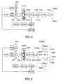
- Fig. 6 is a view showing that the first preferred embodiment of the present invention as illustrated in Fig. 1 is provided with a controllable clutch.
- the centrifugal clutch FC101 and another clutch CL102 controlled by manual, mechanical, electromagnetic, hydraulic power-locking type of or hydraulic coupling type are provided between the engine steering shaft S103 and the load side steering shaft S104 so to execute power coupling or interruption on both of the engine steering shaft S103 and the load side steering shaft S104 for the system to be equipped with a power-locking type or hydraulic coupling type controllable clutch CL102 and engine throttle, to further acquire another specific function for the engine rotation power driven load.
- the steering shaft S103 either directly driven by the engine ICE 101, or through a fixed or variable speed ratio or variable steering transmission or planetary transmission mechanism T104 is coupled to the driven drawn side of the centrifugal clutch FC101 while the load side steering shaft S104 to the drive draw side of the centrifugal clutch FC101. That is, once the load-side steering shaft S104 reaches the preset rpm, the centrifugal clutch FC101 is forthwith closed to draw the steering shaft S103 driven by the engine ECE101.
- the centrifugal clutch FC101 and the controllable clutch CL102 is individually provided or sharing the same structure.
- the preferred embodiment provided with the controllable clutch is essentially comprised of:
- the combination of those structures described above for the system are subject to control by the manual control interface M101, the central control unit CCU101, the drive control device CD101 and the storage discharging device ESD 101.
- the specific system structure described above provides functions related to those described in subparagraphs (1) through (10) or other specific function, it also provides patterns related to those operation patterns described in A1 through A3 or other specific operation pattern.
- Fig. 7 is a view showing that the preferred embodiment given in Fig. 6 is provided with an output clutch. That is, an output clutch CL101 controlled by manual, mechanical, electromagnetic, and hydraulic or centrifugal force is provided to the preferred embodiment illustrated in Fig. 6.
- the output clutch CL101 is provided between the load side steering shaft S104 driven by the primary dynamo-electric unit E101 and the load. When the output clutch CL101 is closed, it provides the same function as those by the preferred embodiment illustrated in Fig.
- Fig. 8 is a schematic view showing that the preferred embodiment illustrated in Fig. 7 is further having the primary dynamo-electric unit replaced by two independent dynamo-electric units respectively provided on the side of two output shafts of a differential gear set.
- the primary dynamo-electric unit E101 of the preferred embodiment in Fig. 7 is replaced by a primary dynamo-electric unit E101R to the right and another primary dynamo-electric unit E101L on the left.
- the primary dynamo-electric unit E101R to the right is directly connected in series with the steering shaft S105R to the right of the differential gear set DG, or alternatively, a one-way or two-way alternatively adapted with a one-way or two-way clutch CLU before being connected in series to the steering shaft S105R to the right of the differential gear set DG.
- the other primary dynamo-electric unit E101L on the left is directly connected in series with a steering shaft S105L to the left of a differential gear set DG or alternatively adapted with a one-way or two-way clutch CLU before being connected in series to the steering shaft S105L to the left of the differential gear set DG.
- the steering shaft S104 on the load side of the centrifugal clutch FC101 is directly outputted to the steering shaft S105 of the differential gear set DG, or through the fixed or variable speed ratio or variable steering transmission or planetary transmission mechanism T103 before being outputted to the steering shaft S105 of the differential gear set DG, or alternatively, by means of the output clutch CL101 controlled by manual, mechanical, electromagnetic, hydraulic or centrifugal force before being outputted to the steering shaft S105 of the differential gear set DG.
- Both of the primary dynamo-electric unit E101R to the right and the other primary dynamo-electric unit E101L on the left are subject to equal speed or differential drive by a drive control device CD101 to provide the same functions as those by the preferred embodiment given in Fig. 7.
- a drive control device CD101 to provide the same functions as those by the preferred embodiment given in Fig. 7.
- Fig. 9 shows a first preferred embodiment of a drive controlled application system by centrifugal clutch of the present invention, essentially comprised of having provided the centrifugal clutch FC101 between the steering shaft S103 driven by the engine ICE 101 and the load side steering shaft S104 to control the operation of coupling or interruption the transmission by both of the steering shafts S103 and S104.
- the steering shaft S103 driven by the engine ICE101 is coupled to the drive draw side of the centrifugal clutch FC101 and the load side steering shaft S104 is coupled to the driven draw side of the centrifugal clutch FC101 so that once the steering shaft S103 which is directly driven by the engine ICE101 or through a fixed speed ratio or variable speed ratio, or variable steering device or planetary transmission mechanism T104 reaches the preset rpm, it drives to close the centrifugal clutch FC 101, thus to draw the load side steering shaft S 104.
- the steering shaft S 104 on the load side is provided to drive the load, and a fixed speed ratio or variable speed ratio or variable steering transmission mechanism T102 is provided to the steering shaft S104 on the load side to engage in mutual transmission with a primary dynamo-electric unit E 101;
- the combination of those structures described above for the system are subject to control by the manual control interface M101, the central control unit CCU101, the drive control device CD101 and the storage discharging device ESD101.
- the specific system structure described above provides functions related to those described in subparagraphs (1) through (10) or other specific function, it also provides patterns related to those operation patterns described in A1 through A3 or other specific operation pattern.
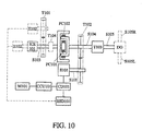
- Fig. 10 shows a second preferred embodiment of the present invention having an application system with a centrifugal clutch provided in the opposite direction as the drive control, essentially comprised of having connected in series a centrifugal clutch FC101 then another centrifugal clutch FC102 between the steering shaft S103 and the drive load side steering shaft S104 of the engine ICE101.
- the double acting centrifugal clutches FC101 and FC102 form to each other or integrated into a 3-layer structure containing an inner layer, an intermediate layer and an outer layer.
- the inner layer and the inner side of the intermediate layer form the centrifugal clutch FC101
- the inner layer incorporated to the load side steering shaft S103 of the engine ICE101 drawn to each other is provided with a drive power-locking unit to act outward when the centrifugal force reaches a preset value
- the outer side of the intermediate layer and the inner side of the outer layer form the centrifugal clutch FC102
- the intermediate layer being coupled to the load side steering shaft S104 having its inner side provided with circumferential coupling surface for power-locking and its outer side provided with a drive power-locking unit acting outward when the centrifugal force reaches its preset value performs the functions as an output clutch with the power-locking circumferential coupling surface on the inner side of the outer layer
- the outer layer is also incorporated to the steering shaft S103 on the side of the engine ICE 101 so to provide linkage with the load when the engine runs at low rpm or is temporarily cut off.
- the steering shaft S 103 either directly driven or driven through a fixed speed ratio or variable speed ratio, or variable steering transmission mechanism or planetary transmission mechanism T104 by the engine is coupled to the drive draw side of the centrifugal clutch FC101 and the load side steering shaft S 104 to the driven draw side of the centrifugal clutch FC101 so to forthwith close the centrifugal clutch FC101and further to draw the steering shaft S103 driven by the engine ICE 101 when the steering shaft S103 on the side of the engine ICE101 reaches its preset rpm.
- a fixed speed ratio or variable speed ratio, or variable steering transmission mechanism or planetary transmission mechanism T102 is provided on the load side steering shaft S104 to engage mutual transmission with the primary dynamo-electric unit;
- the combination of those structures described above for the system are subject to control by the manual control interface M101, the central control unit CCU101, the drive control device CD101 and the storage discharging device ESD 101.
- the specific system structure described above provides functions related to those described in subparagraphs (1) through (10) or other specific function, it also provides patterns related to those operation patterns described in A1 through A3 or other specific operation pattern.
- Fig. 11 shows a third preferred embodiment of the present invention having an application system with a centrifugal clutch provided in the opposite direction as the drive control, essentially comprised of having alternatively provided an output clutch CL301 controlled by manual, mechanical, electromagnetic or hydraulic force between the steering shaft S103 on the side of the engine ICE101 from the preferred embodiment illustrated in Fig. 10 and where between the drive draw side of the double-acting centrifugal clutch FC101 and the driven draw side of the other centrifugal clutch FC102, and subject to the control by the manual control interface M101, the central control unit CCU101, the drive control device CD101 and the storage discharging device ESD101 to provide the same functions as those by the preferred embodiment from Fig.
- Fig. 12 shows a fourth of an application system of the present invention having provided a centrifugal clutch in the opposite direction as the drive control, essentially having the dynamo-electric unit E101 and the load side steering shaft S104 to indicate coaxial structure while the double-acting centrifugal clutches FC101 and FC 102 are provided between the dynamo-electric unit E101 and the engine ICE 101, within, its intermediate structure is provided to be incorporated to the load side steering shaft S104 in the same structure of the output shaft of the primary dynamo-electric unit E101, and its inner and outer layers incorporated to the engine steering shaft S103.
- the double acting centrifugal clutches FC101 and FC102 form to each other or integrated into a 3-layer structure containing an inner layer, an intermediate layer and an outer layer.
- the inner layer and the inner side of the intermediate layer form the centrifugal clutch FC101
- the inner layer incorporated to the engine steering shaft S103 drawn to each other is provided with a drive power-locking unit to act outward when the centrifugal force reaches a preset value
- the outer side of the intermediate layer and the inner side of the outer layer form the centrifugal clutch FC102
- the intermediate layer being coupled to the steering shaft S103 driven by the primary dynamo-electric unit E101 having its inner side provided with circumferential coupling surface for power-locking and its outer side provided with a drive power-locking unit acting outward when the centrifugal force reaches its preset value performs the functions as an output clutch with the power-locking circumferential coupling surface on the inner side of the outer layer.
- the drive draw side of the centrifugal clutch FC101 1 is incorporated to the steering shaft S103 on the side of the engine ICE101 so to couple to the engine to drive the load when the engine runs at high rpm, and to cut off the linkage to the load when the engine runs at low rpm.
- the engine ICE101 is either directly or by means of the steering shaft S103 driven by a fixed speed ratio or variable speed ratio, or variable steering transmission mechanism or planetary transmission mechanism T104, coupled to the drive draw side of the centrifugal clutch FC101 and the driven draw side of the other centrifugal clutch FC102.
- the load side steering shaft S104 is coupled to the driven draw side of the centrifugal clutch FC101 and the drive draw side of the other centrifugal clutch FC102 so that when the load side steering shaft S104 reaches its preset rpm, the other centrifugal clutch FC102 is closed thus to draw the steering shaft S103 driven by the engine ICE101, or when the steering shaft S103 on the side of the engine ICE101 reaches its preset rpm, the centrifugal clutch FC101 is closed, thus to draw the load side steering shaft S104 to drive the load;
- the combination of those structures described above for the system are subject to control by the manual control interface M101, the central control unit CCU101, the drive control device CD101 and the storage discharging device ESD101.
- the specific system structure described above provides functions related to those described in subparagraphs (1) through (10) or other specific function, it also provides patterns related to those operation patterns described in A1 through A3 or other specific operation pattern.
- Fig. 13 is a schematic view showing that the primary dynamo-electric unit in the preferred embodiment of the present invention illustrated in Fig. 12 is replaced by two independent dynamo-electric units respectively provided on two output shafts of the differential gear set; essentially by having the primary dynamo-electric unit E101 in the preferred embodiment illustrated in Fig. 12 to be substituted by two independent primary dynamo-electric units E101R and E101L respectively to the right and left.
- the primary dynamo-electric unit E101R to the right is directly connected or alternatively through a one-way or two-way clutch CLU in series to the steering shaft S105R to the right of the differential gear set DG; and the primary dynamo-electric unit E101L on the left is directly connected or alternatively through a one-way or two-way clutch CLU in series to the steering shaft S105L to the left of the differential gear set DG.
- the steering shaft S104 on the load side of the centrifugal clutch FC101 is directly outputted to the steering shaft S105 of the differential gear set DG, or through the fixed or variable speed ratio or variable steering transmission or planetary transmission mechanism T103 before being outputted to the steering shaft S105 of the differential gear set DG, or alternatively, by means of the output clutch CL101 controlled by manual, mechanical, electromagnetic, hydraulic or centrifugal force before being outputted to the steering shaft S105 of the differential gear set DG.
- Both of the primary dynamo-electric units E101R and another primary dynamo-electric unit E101L are subject to equal speed or differential drive by the drive control device CD101.
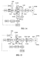
- Fig. 14 shows that the preferred embodiment given in Fig. 9 is further provided with a controllable clutch by having provided a centrifugal clutch FC101 and a controllable CL102 controlled by manual, mechanical, electromagnetic, hydraulic power-locking type of or hydraulic coupling type to be provided between the engine steering shaft S103 and the load side steering shaft S104 so to execute power coupling or interruption on both of the engine steering shaft S103 and the load side steering shaft S104 for the system to be equipped with a power-locking type or hydraulic coupling type controllable clutch CL102 and engine throttle, to further acquire another specific function for the engine rotation power driven load.
- a centrifugal clutch FC101 and a controllable CL102 controlled by manual, mechanical, electromagnetic, hydraulic power-locking type of or hydraulic coupling type to be provided between the engine steering shaft S103 and the load side steering shaft S104 so to execute power coupling or interruption on both of the engine steering shaft S103 and the load side steering shaft S104 for the system to be equipped with a power-locking type or hydraulic coupling type controll
- the steering shaft S103 either directly driven by the engine ICE101, or through a fixed or variable speed ratio or variable steering transmission or planetary transmission mechanism T 104 is coupled to the driven drawn side of the centrifugal clutch FC101 while the load side steering shaft S104 to the drive draw side of the centrifugal clutch FC101. That is, once the steering shaft S103 on the side of the engine ICE 101 reaches its preset rpm, the centrifugal clutch FC101 is forthwith closed to draw the load side steering shaft S104.
- the centrifugal clutch FC101 and the controllable clutch CL102 is individually provided or sharing the same structure; and other units comprising the system are the same as those provided in the preferred embodiment illustrated in Fig. 1.
- the combination of those structures described above for the system are subject to control by the manual control interface M101, the central control unit CCU101, the drive control device CD 101 and the storage discharging device ESD101.
- the specific system structure described above provides functions related to those described in subparagraphs (1) through (10) or other specific function, it also provides patterns related to those operation patterns described in A1 through A3 or other specific operation pattern.
- Fig. 15 is a view showing that the preferred embodiment given in Fig. 14 is provided with an output clutch. That is, an output clutch CL101 controlled by manual, mechanical, electromagnetic, and hydraulic or centrifugal force is provided to the preferred embodiment illustrated in Fig. 14.
- the output clutch CL101 is provided between the load side steering shaft S104 driven by the primary dynamo-electric unit E101 and the load. When the output clutch CL101 is closed, it provides the same function as those by the preferred embodiment illustrated in Fig.
- Fig. 16 is a schematic view showing that the preferred embodiment illustrated in Fig. 15 is further having the primary dynamo-electric unit replaced by two independent dynamo-electric units respectively provided on the side of two output shafts of a differential gear set.
- the primary dynamo-electric unit E101 of the preferred embodiment in Fig. 15 is replaced by a primary dynamo-electric unit E101R to the right and another primary dynamo-electric unit E101L on the left.
- the primary dynamo-electric unit E101R to the right is directly connected in series with the steering shaft S105R to the right of the differential gear set DG, or alternatively, a one-way or two-way alternatively adapted with a one-way or two-way clutch CLU before being connected in series to the steering shaft S105R to the right of the differential gear set DG.
- the other primary dynamo-electric unit E101L on the left is directly connected in series with a steering shaft S105L to the left of a differential gear set DG or alternatively adapted with a one-way or two-way clutch CLU before being connected in series to the steering shaft S105L to the left of the differential gear set DG.
- the steering shaft S104 on the load side of the centrifugal clutch FC101 is directly outputted to the steering shaft S105 of the differential gear set DG, or through the fixed or variable speed ratio or variable steering transmission or planetary transmission mechanism T103 before being outputted to the steering shaft S105 of the differential gear set DG, or alternatively, by means of the output clutch CL101 controlled by manual, mechanical, electromagnetic, hydraulic or centrifugal force before being outputted to the steering shaft S105 of the differential gear set DG.
- Both of the primary dynamo-electric unit E101R to the right and the other primary dynamo-electric unit E101L on the left are subject to equal speed or differential drive by a drive control device CD101 to provide the same functions as those by the preferred embodiment given in Fig. 15.
- Fig. 17 shows that the primary dynamo-electric unit and the load side steering shaft illustrated in Fig. 9 share the same structure.
- the preferred embodiment illustrated in Fig. 9 is further to have the primary dynamo-electric unit E101 and the load side steering shaft S104 to be provided in the same structure, essentially comprised of having provided the centrifugal clutch FC101 between the steering shaft S103 and the load side steering shaft S104 of the engine ICE 101 to control the operation of coupling or interruption the transmission by both of the steering shafts S103 and S104.
- the steering shaft S103 driven by the engine ICE 101 is coupled to the drive draw side of the centrifugal clutch FC101 and the load side steering shaft S104 is coupled to the driven draw side of the centrifugal clutch FC101 so that once the steering shaft S103 which is directly driven by the engine ICE101 or through a fixed speed ratio or variable speed ratio, or variable steering device or planetary transmission mechanism T104 reaches the preset rpm, it drives to close the centrifugal clutch FC101, thus to draw the load side steering shaft S104.
- the steering shaft S104 on the load side is provided to drive the load, and shares the coaxial structure with the primary dynamo-electric unit E101;
- the combination of those structures described above for the system are subject to control by the manual control interface M101, the central control unit CCU101, the drive control device CD 101 and the storage discharging device ESD 101.
- the specific system structure described above provides functions related to those described in subparagraphs (1) through (10) or other specific function, it also provides patterns related to those operation patterns described in A1 through A3 or other specific operation pattern.
- Fig. 18 shows that the preferred embodiment taken from Fig. 17 is provided with a secondary dynamo-electric unit directly coupled to the engine steering shaft or engaging in mutual transmission with the engine steering shaft by means of a transmission mechanism.
- the preferred embodiment when required is provided with the secondary dynamo-electric unit E102 which is directly coupled to the steering shaft S103 of the engine ICE101 or engaging in mutual transmission with the steering shaft S103 of the engine ICE101 1 by means of a variable steering or planetary transmission mechanism T101 with fixed or variable speed ratio so to function at the same time as a generator and as a motor; within,
- the combination of those structures described above for the system are subject to control by the manual control interface M101, the central control unit CCU101, the drive control device CD101 and the storage discharging device ESD101.
- the specific system structure described above provides functions related to those described in subparagraphs (1) through (10) or other specific function, it also provides patterns related to those operation patterns described in A1 through A3 or other specific operation pattern.
- Figs. 17 and 18 show that the primary dynamo-electric unit E101 is further replaced by two independent units of the primary dynamo-electric unit E101R to the right and another primary dynamo-electric unit E101L on the left.
- the primary dynamo-electric unit E101R to the right is directly connected in series with the steering shaft S105R to the right of the differential gear set DG, or alternatively, adapted with a one-way or two-way clutch CLU before being connected in series to the steering shaft S105R to the right of the differential gear set DG while the primary dynamo-electric unit E101L on the left is directly connected in series with the steering shaft S105L to the left of the differential gear set DG, or alternatively, adapted with a one-way or two-way clutch CLU before being connected in series to the steering shaft S 105L to the left of the differential gear set DG.
- the load side steering shaft S 104 of the centrifugal clutch FC101 is directly or through the fixed ratio or variable speed ratio or variable steering transmission mechanism or planetary transmission mechanism T103 outputted to the steering shaft S105 of the differential gear set DG, or alternatively, outputted to the output clutch CL101 before being outputted to the steering shaft S105 of the differential gear set DG.
- both of the primary dynamo-electric units E101R and E101L respectively to the right and the left are subject to drive at equal speed or differential drive by the drive control device CD101.
- Fig. 19 shows that the preferred embodiment taken from Fig. 17 is further having its primary dynamo-electric unit to be replaced by two independent dynamo-electric units respectively provided on the side of two output shafts of the differential gear set.
- Fig. 20 shows that the preferred embodiment taken from Fig. 18 is further having its primary dynamo-electric unit to be replaced by two independent dynamo-electric units respectively provided on the side of two output shafts of the differential gear set.
- an automatic transmission mechanism T1040 is provided between the engine ICE 101 1 and the drive shaft S103 to copy with demands on performance or structural space.
- Fig. 21 shows a preferred embodiment of having an automatic transmission mechanism provided between the engine and the drive shaft of the present invention, essentially comprised of:
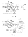
- Figs. 22 through 29 respectively show an application system having a one-way transmission mechanism SWC101 as a drive control connected in series with the driven draw side of the centrifugal clutch FC101 taken from preferred embodiment of Figs. 1 through 8.
- Fig. 22 is a view showing a first preferred embodiment of the application system taken from Fig. 1 that has a one-way transmission mechanism SWC101 as a drive control connected in series with the driven draw side of the centrifugal clutch FC101, essentially comprised of having provided the centrifugal clutch FC101 between the steering shaft S103 driven by the engine ICE101 and the load side transmission shaft S 104 for controlling the operation of the steering shaft S103 and the load side steering shaft S 104 to couple or interrupt transmission, and a one-way transmission mechanism SWC101 selected for steering operation.
- a one-way transmission mechanism SWC101 as a drive control connected in series with the driven draw side of the centrifugal clutch FC101, essentially comprised of having provided the centrifugal clutch FC101 between the steering shaft S103 driven by the engine ICE101 and the load side transmission shaft S 104 for controlling the operation of the steering shaft S103 and the load side steering shaft S 104 to couple or interrupt transmission, and a one-way transmission mechanism SWC101 selected for steering operation.
- the steering shaft S103 driven by the engine ICE 101 is coupled to the driven draw side of the centrifugal clutch FC101 through the one-way transmission mechanism SWC101 selected for steering operation while the load side steering shaft S104 is coupled to the drive draw side of the centrifugal clutch FC101 so that when the load side steering shaft S 104 reaches its preset rpm, the centrifugal clutch FC101 is forthwith closed, thus to draw the steering shaft S103 directly driven by the engine ICE101 or through the fixed speed ratio or variable speed ratio or variable steering transmission mechanism or planetary transmission mechanism T104.
- the load side steering shaft S104 to drive the load is provided with another fixed speed ratio or variable speed ratio or variable steering transmission mechanism or planetary transmission mechanism T102 to engage in mutual transmission with the first primary dynamo-electric unit E101 while other units comprising the system are the same as those provided in the preferred embodiment illustrated in Fig 1;
- the combination of those structures described above for the system are subject to control by the manual control interface M101, the central control unit CCU101, the drive control device CD101 and the storage discharging device ESD101.
- the specific system structure described above provides functions related to those described in subparagraphs (1) through (10) or other specific function, it also provides patterns related to those operation patterns described in A1 through A3 or other specific operation pattern.
- Fig. 23 is a view showing a second preferred embodiment of an application system, within, one-way transmission mechanism as the driven control is connected in series with the driven draw side of the centrifugal clutch of the preferred embodiment taken from Fig. 2, essentially comprised of double-acting centrifugal clutches FC101 and FC102 and the one-way transmission mechanism SWC 101 selected for steering operation connected in sequence between the steering shaft S103 and the drive load side steering shaft S104 of the engine ICE101.
- the double-acting centrifugal clutches is comprised of two units of centrifugal clutches FC101 and FC 102 in a three-layer structure, an inner, an intermediate and an out layers, either by insertion to each other or integrated.
- the inner layer and the inner side of the intermediate layer form the centrifugal clutch FC101.
- the inner layer incorporated to the load side steering shaft S104 drawn to each other is provided with a drive power-locking unit to act outward when the centrifugal force reaches a preset value.
- the outer side of the intermediate layer and the inner side of the outer layer form the centrifugal clutch FC102.
- the intermediate layer related to the one-way transmission mechanism SWC101 selected for steering operation is coupled to the steering shaft S103 driven by the engine.
- the inner side of the intermediate layer is provided with a circumferential coupling surface for power-locking and its outer side is provided with a drive power-locking unit acting outward when the centrifugal force reaches its preset value performs the functions as an output clutch with the power-locking circumferential coupling surface on the inner side of the outer layer.
- the outer layer is also incorporated to the load side steering shaft S104 so to provide linkage with the load when the engine runs at low rpm or is temporarily cut off.
- the steering shaft S103 either directly driven or driven through a fixed speed ratio or variable speed ratio, or variable steering transmission mechanism or planetary transmission mechanism T104 by the engine is coupled to the driven draw side of the centrifugal clutch FC101 and the load side steering shaft S 104 to the drive draw side of the centrifugal clutch FC101 so to forthwith close the centrifugal clutch FC101 and further to draw the steering shaft S 103 driven by the engine ICE101 when the load side steering shaft S 104 reaches its preset rpm.
- a fixed speed ratio or variable speed ratio, or variable steering transmission mechanism or planetary transmission mechanism T102 is provided on the load side steering shaft S104 to engage mutual transmission with the primary dynamo-electric unit while other units comprising the system are the same as those provided in the preferred embodiment illustrated in Fig. 2.
- the combination of those structures described above for the system are subject to control by the manual control interface M101, the central control unit CCU101, the drive control device CD101 and the storage discharging device ESD101.
- the specific system structure described above provides functions related to those described in subparagraphs (1) through (10) or other specific function, it also provides patterns related to those operation patterns described in A1 through A3 or other specific operation pattern.
- Fig. 24 is a view showing a third preferred embodiment of an application system that has a one-way transmission mechanism as the driven control connected in series with the driven draw side of the centrifugal clutch of the preferred embodiment taken from Fig. 3.
- the fixed speed ratio or variable speed ratio, or variable steering transmission mechanism or planetary transmission mechanism T102, the inner circumference of coupling surface for power-locking of the double-acting centrifugal clutch FC101 and the outer circumference of coupling surface for power-locking of the double-acting centrifugal clutch FC102 are jointly incorporated to an intermediate steering shaft S102.
- the double-acting centrifugal clutches are comprised of two units of centrifugal clutches FC101 and FC102 inserted to each other in a three-layer structure, an inner, an intermediate and an out layers.
- the inner layer and the inner side of the intermediate layer form the centrifugal clutch FC101.
- the inner layer incorporated to the intermediate steering shaft S102 drawn to each other is provided with a drive power-locking unit to act outward when the centrifugal force reaches a preset value.
- the outer side of the intermediate layer and the inner side of the outer layer form the centrifugal clutch FC102.
- the intermediate layer related to the one-way transmission mechanism SWC101 selected for steering operation is coupled to the steering shaft S103 driven by the engine.
- the inner side of the intermediate layer is provided with a circumferential coupling surface for power-locking and its outer side is provided with a drive power-locking unit acting outward when the centrifugal force reaches its preset value performs the functions as an output clutch with the power-locking circumferential coupling surface on the inner side of the outer layer.
- the outer layer is also incorporated to the intermediate steering shaft S104 so to provide linkage with the load when the engine runs at low rpm or is temporarily cut off.
- the steering shaft S103 either directly driven or driven through a fixed speed ratio or variable speed ratio, or variable steering transmission mechanism or planetary transmission mechanism T104 by the engine is coupled to the driven draw side of the centrifugal clutch FC101 and the intermediate steering shaft S102 to the drive draw side of the centrifugal clutch FC101 so to forthwith close the centrifugal clutch FC101 and further to draw the steering shaft S103 driven by the engine ICE 101 when the intermediate steering shaft S102 reaches its preset rpm.
- the combination of those structures described above for the system are subject to control by the manual control interface M101, the central control unit CCU101, the drive control device CD101 and the storage discharging device ESD101.
- the specific system structure described above provides functions same as those by the preferred embodiment illustrated in Fig. 23 when the output clutch CL301 is closed; and provides additional function when the output clutch CL301 is disengaged, including functions related to those described in subparagraphs (1) through (10) or other specific function, and operation patterns related to those operation patterns described in A1 through A3 or other specific operation pattern.
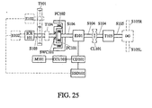
- Fig. 25 is a view showing a fourth preferred embodiment of an application system that has a one-way transmission mechanism as the driven control connected in series with the driven draw side of the centrifugal clutch of the preferred embodiment taken from Fig. 4.
- the primary dynamo-electric unit E101 and the load side steering shaft S104 indicate a coaxial structure, and where between the dynamo-electric unit E101 and the engine ICE 101 are provided with the double-acting centrifugal clutches FC101 and FC102, and the one-way transmission mechanism SWC101 selected for steering operation.
- Both of the inner and the outer structures of the double-acting centrifugal clutches FC101 and FC102 are incorporated to the load side steering shaft S104 coupled to the output shaft of the primary dynamo-electric unit E101 and its intermediate layer structure is mutually incorporated to the steering shaft S 103 driven by the engine ICE101.
- the double-acting centrifugal clutches is comprised of two units of centrifugal clutches FC101 and FC102 inserted to each other in a three-layer structure, an inner, an intermediate and an out layers. Within, the inner layer and the inner side of the intermediate layer form the centrifugal clutch FC101.
- the inner layer incorporated to the load side steering shaft S104 drawn to each other is provided with a drive power-locking unit to act outward when the centrifugal force reaches a preset value.
- the outer side of the intermediate layer and the inner side of the outer layer form the centrifugal clutch FC 102.
- the intermediate layer related to the one-way transmission mechanism SWC101 selected for steering operation is coupled to the steering shaft S103 driven by the engine.
- the inner side of the intermediate layer is provided with a circumferential coupling surface for power-locking and its outer side is provided with a drive power-locking unit acting outward when the centrifugal force reaches its preset value performs the functions as an output clutch with the power-locking circumferential coupling surface on the inner side of the outer layer.
- the outer layer is also incorporated to the load side steering shaft S103 so to provide linkage with the load when the engine runs at low rpm or is temporarily cut off.
- the steering shaft S103 either directly driven or driven through a fixed speed ratio or variable speed ratio, or variable steering transmission mechanism or planetary transmission mechanism T104 by the engine is coupled to the driven draw side of the centrifugal clutch FC101 1 and the load side steering shaft S103 to the drive draw side of the centrifugal clutch FC101 so to forthwith close the centrifugal clutch FC 101 and further to draw the steering shaft S103 driven by the engine ICE 101 when the load side steering shaft S102 reaches its preset rpm.
- the output clutch CL101 when required is provided between the output side of the primary dynamo-electric unit E101 and the fixed speed ratio or variable speed ratio, or variable steering transmission mechanism or planetary transmission mechanism T103.
- the output clutch CL101 is controlled by manual, mechanical, electromagnetic, hydraulic or centrifugal force while the other units comprising the system are the same as those provided in the preferred embodiment illustrated in Fig. 4.
- the combination of those structures described above for the system are subject to control by the manual control interface M101, the central control unit CCU101, the drive control device CD101 and the storage discharging device ESD101.
- the specific system structure described above provides functions related to those described in subparagraphs (1) through (10) or other specific function, it also provides patterns related to those operation patterns described in A1 through A3 or other specific operation pattern.
- Fig. 26 is a schematic view showing the primary dynamo-electric unit in the preferred embodiment illustrated in Fig. 25 is replaced by two independent dynamo-electric units respectively provided on the side of two output shafts of a differential gear set.
- the primary dynamo-electric unit E101 of the preferred embodiment in Fig. 25 is replaced by a primary dynamo-electric unit E101R to the right and another primary dynamo-electric unit E101L on the left.
- the primary dynamo-electric unit E101R to the right is directly connected in series with the steering shaft S105R to the right of the differential gear set DG, or alternatively, a one-way or two-way alternatively adapted with a one-way or two-way clutch CLU before being connected in series to the steering shaft S105R to the right of the differential gear set DG.
- the other primary dynamo-electric unit E101L on the left is directly connected in series with a steering shaft S105L to the left of a differential gear set DG or alternatively adapted with a one-way or two-way clutch CLU before being connected in series to the steering shaft S105L to the left of the differential gear set DG.
- the steering shaft S104 on the load side of the centrifugal clutch FC101 is directly outputted to the steering shaft S105 of the differential gear set DG, or through the fixed or variable speed ratio or variable steering transmission or planetary transmission mechanism T103 before being outputted to the steering shaft S105 of the differential gear set DG, or alternatively, by means of the output clutch CL101 controlled by manual, mechanical, electromagnetic, hydraulic or centrifugal force before being outputted to the steering shaft S105 of the differential gear set DG.
- Both of the primary dynamo-electric unit E101R to the right and the other primary dynamo-electric unit E101L on the left are subject to equal speed or differential drive by a drive control device CD 101.
- Fig. 27 is a view showing that the preferred embodiment of the present invention illustrated in Fig. 22 is provided with a controllable clutch.
- the centrifugal clutch FC101 and a clutch CL 102 controlled by manual, mechanical, electromagnetic, hydraulic power-locking type of or hydraulic coupling type are provided between the engine steering shaft S103 and the load side steering shaft S104 so to execute power coupling or interruption on both of the engine steering shaft S103 and the load side steering shaft S104 for the system to be equipped with a power-locking type or hydraulic coupling type controllable clutch CL102 and engine throttle, to further acquire another specific function for the engine rotation power driven load.
- the steering shaft S103 either directly driven by the engine ICE 101, or through a fixed or variable speed ratio or variable steering transmission or planetary transmission mechanism T104 is coupled to the driven drawn side of the centrifugal clutch FC101 while the load side steering shaft S104 to the drive draw side of the centrifugal clutch FC101. That is, once the load-side steering shaft S104 reaches the preset rpm, the centrifugal clutch FC101 is forthwith closed to draw the steering shaft S103 driven by the engine ECE101.
- the centrifugal clutch FC101 and the controllable clutch CL102 is individually provided or sharing the same structure.
- the combination of those structures described above for the system are subject to control by the manual control interface M101, the central control unit CCU101, the drive control device CD101 and the storage discharging device ESD101.
- the specific system structure described above provides functions related to those described in subparagraphs (1) through (10) or other specific function, it also provides patterns related to those operation patterns described in A1 through A3 or other specific operation pattern.
- Fig. 28 shows the preferred embodiment illustrated in Fig. 27 is provided with an output clutch.
- an output clutch CL101 controlled by manual, mechanical, electromagnetic, hydraulic or centrifugal force.
- the output clutch CL101 is provided between the load side steering shaft S104 driven by the primary dynamo-electric unit E101 and the load. When the output clutch CL101 is closed, it provides the same function as those by the preferred embodiment illustrated in Fig.
- Fig. 29 is a schematic view showing that the preferred embodiment given in Fig. 28 has the primary dynamo-electric unit to be replaced by two independent dynamo-electric units respectively provided on the side of two output shafts of the differential gear set.
- the primary dynamo-electric unit E101 of the preferred embodiment in Fig. 28 is replaced by a primary dynamo-electric unit E101R to the right and another primary dynamo-electric unit E101L on the left.
- the primary dynamo-electric unit E101R to the right is directly connected in series with the steering shaft S 105R to the right of the differential gear set DG, or alternatively, a one-way or two-way alternatively adapted with a one-way or two-way clutch CLU before being connected in series to the steering shaft S105R to the right of the differential gear set DG.
- the other primary dynamo-electric unit E101L on the left is directly connected in series with a steering shaft S105L to the left of a differential gear set DG or alternatively adapted with a one-way or two-way clutch CLU before being connected in series to the steering shaft S105L to the left of the differential gear set DG.
- the steering shaft S104 on the load side of the centrifugal clutch FC101 is directly outputted to the steering shaft S105 of the differential gear set DG, or through the fixed or variable speed ratio or variable steering transmission or planetary transmission mechanism T103 before being outputted to the steering shaft S105 of the differential gear set DG, or alternatively, by means of the output clutch CL101 controlled by manual, mechanical, electromagnetic, hydraulic or centrifugal force before being outputted to the steering shaft S105 of the differential gear set DG.
- Both of the primary dynamo-electric unit E101R to the right and the other primary dynamo-electric unit E101L on the left are subject to equal speed or differential drive by a drive control device CD101to provide the same functions as those by the preferred embodiment given in Fig. 28. D.
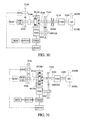
- Fig. 30 shows that a first preferred embodiment of a drive application system the present invention is comprised of having the centrifugal clutch from the preferred embodiment of Fig. 22 to be provided in opposite direction and a one-way transmission mechanism selected for steering operation.
- the centrifugal clutch FC101 is provided between the steering shaft S 103 driven by the engine ICE101 and the load side steering shaft S104 to control the operation of coupling or interruption the transmission by both of the steering shafts S103 and S104.
- the steering shaft S103 driven by the engine ICE101 is coupled to the drive draw side of the centrifugal clutch FC101 and the load side steering shaft S104 is coupled to the driven draw side of the centrifugal clutch FC101 1 so that once the steering shaft S103 which is directly driven by the engine ICE101 or through a fixed speed ratio or variable speed ratio, or variable steering device or planetary transmission mechanism T104 reaches the preset rpm, it drives to close the centrifugal clutch FC101, thus to draw the load side steering shaft S104.
- the steering shaft S104 on the load side is provided to drive the load, and a fixed speed ratio or variable speed ratio or variable steering transmission mechanism T102 is provided to the steering shaft S104 on the load side to engage in mutual transmission with a primary dynamo-electric unit E101 while the other units comprising the system are the same as those provided in the preferred embodiment illustrated in Fig. 9;
- the combination of those structures described above for the system are subject to control by the manual control interface M101, the central control unit CCU101, the drive control device CD101 and the storage discharging device ESD101.
- the specific system structure described above provides functions related to those described in subparagraphs (1) through (10) or other specific function, it also provides patterns related to those operation patterns described in A1 through A3 or other specific operation pattern.
- Fig. 31 shows that a second preferred embodiment of a drive application system the present invention is comprised of having the centrifugal clutch from the preferred embodiment of Fig. 23 to be provided in opposite direction and a one-way transmission mechanism selected for steering operation.
- the double-acting centrifugal clutches FC101 and FC102 are connected in series between the steering shaft S103 and the drive load side steering shaft S104 of the engine ICE 101.
- the double acting centrifugal clutches FC101 and FC102 form to each other by insertion or are integrated into a 3-layer structure containing an inner layer, an intermediate layer and an outer layer.
- the inner layer and the inner side of the intermediate layer form the centrifugal clutch FC101, the inner layer incorporated to the steering shaft S 103 on the side of the engine ICE 101 drawn to each other is provided with a drive power-locking unit to act outward when the centrifugal force reaches a preset value; the outer side of the intermediate layer and the inner side of the outer layer form the centrifugal clutch FC102; the intermediate layer being coupled to the load side steering shaft S103 having its inner side provided with circumferential coupling surface for power-locking and its outer side provided with a drive power-locking unit acting outward when the centrifugal force reaches its preset value performs the functions as an output clutch with the power-locking circumferential coupling surface on the inner side of the outer layer; and the outer layer is also incorporated to the steering shaft S103 on the side of the engine ICE 101 so to provide linkage with the load when the engine runs at low rpm or is temporarily cut off.
- the load side steering shaft S103 either directly driven or driven through a fixed speed ratio or variable speed ratio, or variable steering transmission mechanism or planetary transmission mechanism T104 by the engine is coupled through the one-way transmission mechanism SWC101 selected for steering operation to the drive draw side of the centrifugal clutch FC101 and the load side steering shaft S 104 to the driven draw side of the centrifugal clutch FC101 so to forthwith close the centrifugal clutch FC101 and further to draw the load side steering shaft S 104 when the load side steering shaft S104 reaches its preset rpm.
- a fixed speed ratio or variable speed ratio, or variable steering transmission mechanism or planetary transmission mechanism T 102 is provided on the load side steering shaft S104 to engage mutual transmission with the primary dynamo-electric unit; while the other units comprising the system are the same as those provided in the preferred embodiment illustrated in Fig. 10;
- the combination of those structures described above for the system are subject to control by the manual control interface M101, the central control unit CCU101, the drive control device CD 101 and the storage discharging device ESD101.
- the specific system structure described above provides functions related to those described in subparagraphs (1) through (10) or other specific function, it also provides patterns related to those operation patterns described in A1 through A3 or other specific operation pattern;
- Fig. 32 shows that a third preferred embodiment of a drive application system the present invention is comprised of having the centrifugal clutch from the preferred embodiment of Fig. 24 to be provided in opposite direction and a one-way transmission mechanism selected for steering operation.
- an output clutch CL301 controlled by manual, mechanical, electromagnetic or hydraulic force is alternatively provided between the steering shaft S103 on the side of the engine ICE101 and the double-acting centrifugal clutches at where between the drive draw side of the centrifugal clutch FC101 and the driven draw side of the centrifugal clutch FC102 while the other units comprising the system are the same as those provided in the preferred embodiment illustrated in Fig. 11;
- the combination of those structures described above for the system are subject to control by the manual control interface M101, the central control unit CCU101, the drive control device CD101 and the storage discharging device ESD101.
- the specific system structure described above provides same functions same as those by the preferred embodiment illustrated in Fig. 31 when the output clutch CL301 is closed; and when the output clutch CL301 is disengaged, the specific system structure described above provides additional functions related to those described in subparagraphs (1) through (10) or other specific function, it also provides patterns related to those operation patterns described in A1 through A3 or other specific operation pattern.
- Fig. 33 shows that a fourth preferred embodiment of a drive application system the present invention is comprised of having the centrifugal clutch from the preferred embodiment of Fig. 25 to be provided in opposite direction and a one-way transmission mechanism selected for steering operation.
- the dynamo-electric unit E101 and the load side steering shaft S104 indicate a coaxial structure with the double-acting centrifugal clutches FC101 and FC102 provided between the dynamo-electric unit E101 and the engine ICE101.
- the intermediate structure is provided to be incorporated to the load side steering shaft S 104 in the same structure of the output shaft of the primary dynamo-electric unit E101, and its inner and outer layers incorporated to the engine steering shaft S103.
- the double acting centrifugal clutches FC101 and FC102 form to each other or integrated into a 3-layer structure containing an inner layer, an intermediate layer and an outer layer.
- the inner layer and the inner side of the intermediate layer form the centrifugal clutch FC101
- the inner layer incorporated to the engine steering shaft S 103 drawn to each other is provided with a drive power-locking unit to act outward when the centrifugal force reaches a preset value
- the outer side of the intermediate layer and the inner side of the outer layer form the centrifugal clutch FC102
- the intermediate layer being coupled to the steering shaft S103 driven by the primary dynamo-electric unit E101 having its inner side provided with circumferential coupling surface for power-locking and its outer side provided with a drive power-locking unit acting outward when the centrifugal force reaches its preset value performs the functions as an output clutch with the power-locking circumferential coupling surface on the inner side of the outer layer.
- the drive draw side of the centrifugal clutch FC101 is incorporated to the steering shaft S 103 on the side of the engine ICE 101 so to couple to the engine to drive the load when the engine runs at high rpm, and to cut off the linkage to the load when the engine runs at low rpm.
- the engine ICE 101 is either directly or by means of the steering shaft S103 driven by a fixed speed ratio or variable speed ratio, or variable steering transmission mechanism or planetary transmission mechanism T104, coupled to the drive draw side of the centrifugal clutch FC101 and the driven draw side of the other centrifugal clutch FC102.
- the load side steering shaft S104 is coupled to the driven draw side of the centrifugal clutch FC101 and the drive draw side of the other centrifugal clutch FC102 so that when the load side steering shaft S104 reaches its preset rpm, the other centrifugal clutch FC102 is closed thus to draw the steering shaft S103 driven by the engine ICE 101, or when the steering shaft S103 on the side of the engine ICE 101 reaches its preset rpm, the centrifugal clutch FC101 is closed, thus to draw the load side steering shaft S104 to drive the load;
- the output clutch CL101 is provided at where between the output side of the primary dynamo-electric unit E101 and the fixed speed, or variable speed ratio or variable steering transmission mechanism or planetary transmission mechanism T103.
- the output clutch CL101 is controlled by manual, mechanical, electromagnetic, hydraulic or centrifugal force while the other units comprising the system are the same as those provided in the preferred embodiment illustrated in Fig. 12;
- the combination of those structures described above for the system are subject to control by the manual control interface M101, the central control unit CCU101, the drive control device CD 101 and the storage discharging device ESD 101.
- the specific system structure described above provides functions related to those described in subparagraphs (1) through (10) or other specific function, it also provides patterns related to those operation patterns described in A1 through A3 or other specific operation pattern.
- Fig. 34 is a schematic view showing that the primary dynamo-electric unit in the preferred embodiment taken from Fig. 33 is replaced by two independent dynamo-electric units respectively provided on the side of two output shafts of the differential gear set.
- the primary dynamo-electric unit E101 of the preferred embodiment in Fig. 33 is replaced by a primary dynamo-electric unit E101R to the right and another primary dynamo-electric unit E101L on the left.
- the primary dynamo-electric unit E101R to the right is directly connected in series with the steering shaft S105R to the right of the differential gear set DG, or alternatively, a one-way or two-way alternatively adapted with a one-way or two-way clutch CLU before being connected in series to the steering shaft S105R to the right of the differential gear set DG.
- the other primary dynamo-electric unit E101L on the left is directly connected in series with a steering shaft S105L to the left of a differential gear set DG or alternatively adapted with a one-way or two-way clutch CLU before being connected in series to the steering shaft S105L to the left of the differential gear set DG.
- the steering shaft S104 on the load side of the centrifugal clutch FC101 is directly outputted to the steering shaft 5105 of the differential gear set DG, or through the fixed or variable speed ratio or variable steering transmission or planetary transmission mechanism T103 before being outputted to the steering shaft S105 of the differential gear set DG, or alternatively, by means of the output clutch CL101 controlled by manual, mechanical, electromagnetic, hydraulic or centrifugal force before being outputted to the steering shaft S105 of the differential gear set DG.
- Both of the primary dynamo-electric unit E101R to the right and the other primary dynamo-electric unit E101L on the left are subject to equal speed or differential drive by a drive control device CD101.
- Fig. 35 shows that the preferred embodiment of Fig. 30 is provided with a controllable clutch.
- a centrifugal the centrifugal clutch FC101 and another clutch CL102 controlled by manual, mechanical, electromagnetic, hydraulic power-locking type of or hydraulic coupling type are provided between the engine steering shaft S103 and the load side steering shaft S104 so to execute power coupling or interruption on both of the engine steering shaft S103 and the load side steering shaft S104 for the system to be equipped with a power-locking type or hydraulic coupling type controllable clutch CL102 and engine throttle, to further acquire another specific function for the engine rotation power driven load.
- the steering shaft S 103 either directly driven by the engine ICE 101, or through a fixed or variable speed ratio or variable steering transmission or planetary transmission mechanism T 104 is coupled to the drive drawn side of the centrifugal clutch FC 101 while the load side steering shaft S104 to the driven draw side of the centrifugal clutch FC101. That is, once the steering shaft S103 on the side of the engine ICE 101 reaches the preset rpm, the centrifugal clutch FC101 is forthwith closed to draw the load side steering shaft S104.
- the centrifugal clutch FC101 and the controllable clutch CL102 is individually provided or sharing the same structure, while the other units comprising the system are the same as those provided in the preferred embodiment illustrated in Fig. 30.
- the combination of those structures described above for the system are subject to control by the manual control interface M101, the central control unit CCU101, the drive control device CD101 and the storage discharging device ESD101.
- the specific system structure described above provides functions related to those described in subparagraphs (1) through (10) or other specific function, it also provides patterns related to those operation patterns described in A1 through A3 or other specific operation pattern.
- Fig. 36 shows that the preferred embodiment of Fig. 35 is provided with an output clutch.
- the preferred embodiment taken from Fig. 35 being further provided with an output clutch CL101 controlled by manual, mechanical, electromagnetic, hydraulic or centrifugal force is disposed at where between the load side steering S104 driven by the primary dynamo-electric unit E101 and the load.
- the output shaft CL101 When the output shaft CL101 is closed, it provides the same functions as those by the preferred embodiment given in Fig.
- the engine ICE101 simultaneously drives the primary dynamo-electric unit E101 and the secondary dynamo-electric unit E102 to operate as a generator or the primary dynamo-electric unit E101 is driven alone to operate as a generator and also provides additional functions related to those described in subparagraphs (1) through (10) or other specific function, it also provides patterns related to those operation patterns described in A1 through A3 or other specific operation pattern.
- Fig. 37 is a schematic view showing that the primary dynamo-electric unit in the preferred embodiment taken from Fig. 36 is replaced by two independent dynamo-electric units respectively provided on the side of two output shafts of the differential gear set.
- the primary dynamo-electric unit E101 of the preferred embodiment in Fig. 36 is replaced by a primary dynamo-electric unit E101R to the right and another primary dynamo-electric unit E101L on the left.
- the primary dynamo-electric unit E101R to the right is directly connected in series with the steering shaft S105R to the right of the differential gear set DG, or alternatively, a one-way or two-way alternatively adapted with a one-way or two-way clutch CLU before being connected in series to the steering shaft S105R to the right of the differential gear set DG.
- the other primary dynamo-electric unit E101L on the left is directly connected in series with a steering shaft S105L to the left of a differential gear set DG or alternatively adapted with a one-way or two-way clutch CLU before being connected in series to the steering shaft S105L to the left of the differential gear set DG.
- the steering shaft S104 on the load side of the centrifugal clutch FC101 is directly outputted to the steering shaft S105 of the differential gear set DG, or through the fixed or variable speed ratio or variable steering transmission or planetary transmission mechanism T103 before being outputted to the steering shaft S105 of the differential gear set DG, or alternatively, by means of the output clutch CL101 controlled by manual, mechanical, electromagnetic, hydraulic or centrifugal force before being outputted to the steering shaft S105 of the differential gear set DG.
- Both of the primary dynamo-electric unit E101R to the right and the other primary dynamo-electric unit E101L on the left are subj ect to equal speed or differential drive by a drive control device CD101, while providing the same functions as those provided in the preferred embodiment illustrated in Fig.
- E. Fig. 38 through 45 show that preferred embodiments of the application system are provided in each preferred embodiment with a one-way transmission mechanism SWC 101 between the steering shaft S 103 incorporated to the engine ICE 101 and the driven draw side of the centrifugal clutch FC101, and the output shaft S 104 incorporated to the drive draw side of the centrifugal clutch FC101.
- Fig, 38 shows a first preferred embodiment of an application system taken from the preferred embodiment illustrated in Fig. 1, which is changed to that a one-way transmission mechanism is provided between the steering shaft of the engine incorporated to the driven draw side of the centrifugal clutch and the output shaft incorporated to the drive draw side of the centrifugal clutch.
- the centrifugal clutch FC101 and the one-way transmission mechanism SWC 101 selected for steering operation to control the operation of both steering shafts S103 and S104 to couple or interrupt transmission is provided between the steering shaft S103 driven by the engine ICE101 and the load side steering shaft S104.
- the steering shaft S103 driven by the engine ICE101 The steering shaft S103 driven by the engine ICE101.
- the centrifugal clutch FC101 is coupled to the driven draw side of the centrifugal clutch FC101 while the load side steering shaft S104 is coupled to the drive draw side of the centrifugal clutch FC101 so that when the load side steering shaft S104 reaches its preset rpm, the centrifugal clutch FC101 is forthwith closed, thus to draw the steering shaft S103 either directly driven by the engine ICE101 or via the fixed or variable speed ratio or variable steering transmission or planetary transmission mechanism T104; the load side steering shaft S104 is provided to drive the load and a fixed or variable speed ratio or variable steering transmission or planetary transmission mechanism T102 may be provided on the load side steering shaft S104 to engage mutual transmission with the primary dynamo-electric unit E101 while the other units comprising the system are the same as those provided in the preferred embodiment illustrated in Fig. 1;
- the combination of those structures described above for the system are subject to control by the manual control interface M101, the central control unit CCU101, the drive control device CD 101 and the storage discharging device ESD101.
- the specific system structure described above provides functions related to those described in subparagraphs (1) through (10) or other specific function, it also provides patterns related to those operation patterns described in A1 through A3 or other specific operation pattern.
- Fig, 39 shows a second preferred embodiment of an application system taken from the preferred embodiment illustrated in Fig. 2.
- a one-way transmission mechanism is provided between the steering shaft of the engine incorporated to the driven draw side of the centrifugal clutch and the output shaft incorporated to the drive draw side of the centrifugal clutch.
- the double-acting centrifugal clutches FC101 and FC 102 are connected in series and in sequence between the steering shaft S103 and the load side steering shaft S104 of the engine ICE101, and on the one-way transmission mechanism SWC101 selected for steering operation.
- the double acting centrifugal clutches FC101 and FC102 form to each other or integrated into a 3-layer structure containing an inner layer, an intermediate layer and an outer layer.
- the inner layer and the inner side of the intermediate layer form the centrifugal clutch FC101
- the inner layer incorporated to the load side steering shaft S104 drawn to each other is provided with a drive power-locking unit to act outward when the centrifugal force reaches a preset value
- the outer side of the intermediate layer and the inner side of the outer layer form the centrifugal clutch FC 102
- the intermediate layer being coupled to the steering shaft S103 driven by the engine having its inner side provided with circumferential coupling surface for power-locking and its outer side provided with a drive power-locking unit acting outward when the centrifugal force reaches its preset value performs the functions as an output clutch with the power-locking circumferential coupling surface on the inner side of the outer layer
- the outer layer is also incorporated to the load side steering shaft S104 so to provide linkage with the load when the engine runs at low rpm or is temporarily cut off.
- the steering shaft S103 either directly driven or driven through a fixed speed ratio or variable speed ratio, or variable steering transmission mechanism or planetary transmission mechanism T104 by the engine is coupled to the driven draw side of the centrifugal clutch FC101 and the load side steering shaft S104 to the drive draw side of the centrifugal clutch FC101 so to forthwith close the centrifugal clutch FC101 and further to draw the steering shaft S103 driven by the engine ICE101 when the load side steering shaft S104 reaches its preset rpm.
- a fixed speed ratio or variable speed ratio, or variable steering transmission mechanism or planetary transmission mechanism T102 is provided on the load side steering shaft S104 to engage mutual transmission with the primary dynamo-electric unit while the other units comprising the system are the same as those disclosed in the preferred embodiment illustrated in Fig. 2;
- the combination of those structures described above for the system are subject to control by the manual control interface M101, the central control unit CCU101, the drive control device CD 101 and the storage discharging device ESD 101.
- the specific system structure described above provides functions related to those described in subparagraphs (1) through (10) or other specific function, it also provides patterns related to those operation patterns described in A1 through A3 or other specific operation pattern.
- Fig, 40 shows a third preferred embodiment of an application system taken from the preferred embodiment illustrated in Fig. 3.
- a one-way transmission mechanism is provided between the steering shaft of the engine incorporated to the driven draw side of the centrifugal clutch and the output shaft incorporated to the drive draw side of the centrifugal clutch.
- the fixed speed ratio or variable speed ratio, or variable steering transmission mechanism or planetary transmission mechanism T102 taken from the preferred embodiment illustrated I Fig. 39 are jointly incorporated to the intermediate steering shaft S102 with the coupling surface of the inner circumference of the double-acting centrifugal clutch FC101 for power locking and the coupling surface of the outer circumference of the double-acting centrifugal clutch FC102.
- the double-acting centrifugal clutches are comprised of two units of centrifugal clutches FC101 and FC 102 inserted to each other in a three-layer structure, an inner, an intermediate and an out layers.
- the inner layer and the inner side of the intermediate layer form the centrifugal clutch FC101.
- the inner layer incorporated to the intermediate steering shaft S102 drawn to each other is provided with a drive power-locking unit to act outward when the centrifugal force reaches a preset value.
- the outer side of the intermediate layer and the inner side of the outer layer form the centrifugal clutch FC102.
- the intermediate layer related to the one-way transmission mechanism SWC101 selected for steering operation is coupled to the steering shaft S103 driven by the engine.
- the inner side of the intermediate layer is provided with a circumferential coupling surface for power-locking and its outer side is provided with a drive power-locking unit acting outward when the centrifugal force reaches its preset value performs the functions as an output clutch with the power-locking circumferential coupling surface on the inner side of the outer layer.
- the outer layer is also incorporated to the intermediate steering shaft S104 so to provide linkage with the load when the engine runs at low rpm or is temporarily cut off.
- the steering shaft S103 either directly driven or driven through a fixed speed ratio or variable speed ratio, or variable steering transmission mechanism or planetary transmission mechanism T104 by the engine is coupled to the driven draw side of the centrifugal clutch FC101, and the one-way transmission mechanism SWC101 selected for steering operation is provided between the steering shaft S103 and the intermediate shaft S102 while the intermediate shaft S 102 is coupled to the drive draw side of the centrifugal clutch FC101 so to forthwith close the centrifugal clutch FC101 and further to draw the steering shaft S103 driven by the engine ICE101 when the intermediate steering shaft S102 reaches its preset rpm;
- the combination of those structures described above for the system are subject to control by the manual control interface M101, the central control unit CCU101, the drive control device CD101 and the storage discharging device ESD101.
- the specific system structure described above provides same functions same as those by the preferred embodiment illustrated in Fig. 39 when the output clutch CL301 is closed; and when the output clutch CL301 is disengaged, the specific system structure described above provides additional functions related to those described in subparagraphs (1) through (10) or other specific function, it also provides patterns related to those operation patterns described in A1 through A3 or other specific operation pattern.
- Fig, 41 shows a fourth preferred embodiment of an application system taken from the preferred embodiment illustrated in Fig. 4. Wherein a one-way transmission mechanism is provided between the steering shaft of the engine incorporated to the driven draw side of the centrifugal clutch and the output shaft incorporated to the drive draw side of the centrifugal clutch.
- the primary dynamo-electric unit E101 and the load side steering shaft S104 indicate coaxial structure and the double-acting centrifugal clutches FC101 and FC102 are provided between the dynamo-electric unit E101 and the engine ICE 101 with its inner and outer structures to be incorporated to the load side steering shaft S104 incorporated to the output terminal of the primary dynamo-electric unit E101 and its intermediate structure is incorporated to the steering shaft S103 driven by the engine ICE101.
- the double-acting centrifugal clutches is comprised of two units of centrifugal clutches FC101 and FC 102 inserted to each other in a three-layer structure, an inner, an intermediate and an out layers.
- the inner layer and the inner side of the intermediate layer form the centrifugal clutch FC101.
- the inner layer incorporated to the load side steering shaft S104 drawn to each other is provided with a drive power-locking unit to act outward when the centrifugal force reaches a preset value.
- the outer side of the intermediate layer and the inner side of the outer layer form the centrifugal clutch FC102.
- the intermediate layer related to the one-way transmission mechanism SWC101 selected for steering operation is coupled to the steering shaft S103 driven by the engine.
- the inner side of the intermediate layer is provided with a circumferential coupling surface for power-locking and its outer side is provided with a drive power-locking unit acting outward when the centrifugal force reaches its preset value performs the functions as an output clutch with the power-locking circumferential coupling surface on the inner side of the outer layer.
- the outer layer is also incorporated to the load side steering shaft S104 so to provide linkage with the load when the engine runs at high speed and to cut off the linkage to the load when the engine runs at low speed.
- the steering shaft S103 either directly driven or driven through a fixed speed ratio or variable speed ratio, or variable steering transmission mechanism or planetary transmission mechanism T104 by the engine is coupled to the driven draw side of the centrifugal clutch FC101 and the load side steering shaft S103 to the driven draw side of the centrifugal clutch FC101.
- the one-way transmission mechanism SWC101 selected for steering operation is provided between the steering shaft S103 and the load side steering shaft S104 and the load side steering shaft S104 is incorporated to the drive draw side of the centrifugal clutch FC101 so that once the load side steering shaft S104 reaches its rpm, the centrifugal clutch FC101 is closed thus to draw the steering shaft S103 driven by the engine ICE101.
- the output clutch CL101 when required is provided between the output side of the primary dynamo-electric unit E101 and the fixed speed ratio or variable speed ratio, or variable steering transmission mechanism or planetary transmission mechanism T103.
- the output clutch CL101 is controlled by manual, mechanical, electromagnetic, hydraulic or centrifugal force while the other units comprising the system are the same as those provided in the preferred embodiment illustrated in Fig. 4;
- the combination of those structures described above for the system are subject to control by the manual control interface M101, the central control unit CCU101, the drive control device CD101 and the storage discharging device ESD 101.
- the specific system structure described above provides functions related to those described in subparagraphs (1) through (10) or other specific function, it also provides patterns related to those operation patterns described in A1 through A3 or other specific operation pattern.
- Fig. 42 is a schematic view showing that the preferred embodiment illustrated in Fig. 41 is further having the primary dynamo-electric unit replaced by two independent dynamo-electric units respectively provided on the side of two output shafts of a differential gear set.
- the primary dynamo-electric unit E101 of the preferred embodiment in Fig. 41 is replaced by a primary dynamo-electric unit E101R to the right and another primary dynamo-electric unit E101L on the left.
- the primary dynamo-electric unit E101R to the right is directly connected in series with the steering shaft S105R to the right of the differential gear set DG, or alternatively, a one-way or two-way alternatively adapted with a one-way or two-way clutch CLU before being connected in series to the steering shaft S105R to the right of the differential gear set DG.
- the other primary dynamo-electric unit E101L on the left is directly connected in series with a steering shaft S105L to the left of a differential gear set DG or alternatively adapted with a one-way or two-way clutch CLU before being connected in series to the steering shaft S105L to the left of the differential gear set DG.
- the steering shaft S104 on the load side of the centrifugal clutch FC101 is directly outputted to the steering shaft S105 of the differential gear set DG, or through the fixed or variable speed ratio or variable steering transmission or planetary transmission mechanism T103 before being outputted to the steering shaft S105 of the differential gear set DG, or alternatively, by means of the output clutch CL101 controlled by manual, mechanical, electromagnetic, hydraulic or centrifugal force before being outputted to the steering shaft S105 of the differential gear set DG.
- Both of the primary dynamo-electric unit E101R to the right and the other primary dynamo-electric unit E101L on the left are subject to equal speed or differential drive by a drive control device CD101.
- Fig. 43 is a view showing that the preferred embodiment taken from Fig. 38 of the present invention is provided with a controllable clutch.
- the centrifugal clutch FC101 and another clutch CL102 controlled by manual, mechanical, electromagnetic, hydraulic power-locking type of or hydraulic coupling type are provided between the engine steering shaft S103 and the load side steering shaft S104 so to execute power coupling or interruption on both of the engine steering shaft S103 and the load side steering shaft S104 for the system to be equipped with a power-locking type or hydraulic coupling type controllable clutch CL102 and engine throttle, to further acquire another specific function for the engine rotation power driven load.
- the steering shaft S103 either directly driven by the engine ICE101, or through a fixed or variable speed ratio or variable steering transmission or planetary transmission mechanism T104 is coupled to the driven drawn side of the centrifugal clutch FC101 while the load side steering shaft S104 to the drive draw side of the centrifugal clutch FC101. That is; once the load-side steering shaft S104 reaches the preset rpm, the centrifugal clutch FC101 is forthwith closed to draw the steering shaft S103 driven by the engine ICE101.
- the centrifugal clutch FC101 and the controllable clutch CL102 is individually provided or sharing the same structure;
- the combination of those structures described above for the system are subj ect to control by the manual control interface M101, the central control unit CCU101, the drive control device CD101 and the storage discharging device ESD 101.
- the specific system structure described above provides functions related to those described in subparagraphs (1) through (10) or other specific function, it also provides patterns related to those operation patterns described in A1 through A3 or other specific operation pattern.
- Fig. 44 is a view showing that the preferred embodiment given in Fig. 43 is provided with an output clutch.
- an output clutch CL101 controlled by manual, mechanical, electromagnetic, and hydraulic or centrifugal force is provided to the preferred embodiment illustrated in Fig. 43.
- the output clutch CL101 is provided between the load side steering shaft S104 driven by the primary dynamo-electric unit E101 and the load. When the output clutch CL101 is closed, it provides the same function as those by the preferred embodiment illustrated in Fig.
- Fig. 45 is a schematic view showing that the preferred embodiment illustrated in Fig. 44 is further having the primary dynamo-electric unit replaced by two independent dynamo-electric units respectively provided on the side of two output shafts of a differential gear set.
- the primary dynamo-electric unit E101 of the preferred embodiment in Fig. 44 is replaced by a primary dynamo-electric unit E101R to the right and another primary dynamo-electric unit E101L on the left.
- the primary dynamo-electric unit E101R to the right is directly connected in series with the steering shaft S105R to the right of the differential gear set DG, or alternatively, a one-way or two-way alternatively adapted with a one-way or two-way clutch CLU before being connected in series to the steering shaft S105R to the right of the differential gear set DG.
- the other primary dynamo-electric unit E101L on the left is directly connected in series with a steering shaft S105L to the left of a differential gear set DG or alternatively adapted with a one-way or two-way clutch CLU before being connected in series to the steering shaft S105L to the left of the differential gear set DG.
- the steering shaft S104 on the load side of the centrifugal clutch FC101 is directly outputted to the steering shaft S105 of the differential gear set DG, or through the fixed or variable speed ratio or variable steering transmission or planetary transmission mechanism T103 before being outputted to the steering shaft S105 of the differential gear set DG, or alternatively, by means of the output clutch CL101 controlled by manual, mechanical, electromagnetic, hydraulic or centrifugal force before being outputted to the steering shaft S105 of the differential gear set DG.
- Both of the primary dynamo-electric unit E101R to the right and the other primary dynamo-electric unit E101L on the left are subject to equal speed or differential drive by a drive control device CD101 for providing functions same as those described for the preferred embodiment illustrated in Fig. 44. F.
- Fig. 46 shows that a first preferred embodiment of a drive application system the present invention is comprised of having the centrifugal clutch from the preferred embodiment of Fig. 38 to be provided in opposite direction and a one-way transmission mechanism selected for steering operation.
- the centrifugal clutch FC101 is provided between the steering shaft S103 driven by the engine ICE101 and the load side steering shaft S104 to control the operation of coupling or interruption the transmission by both of the steering shafts S103 and S104.
- the steering shaft S103 driven by the engine ICE101 is coupled to the drive draw side of the centrifugal clutch FC101 and the load side steering shaft S104 is coupled to the driven draw side of the centrifugal clutch FC101.
- the one-way transmission mechanism SWC 101 is provided between the drive steering shaft S103 and the load side steering shaft S104 driven by the engine ICE101 so that once the steering shaft S103 which is directly driven by the engine ICE101 or through a fixed speed ratio or variable speed ratio, or variable steering device or planetary transmission mechanism T104 reaches the preset rpm, it drives to close the centrifugal clutch FC101, thus to draw the load side steering shaft S104.
- the steering shaft S104 on the load side is provided to drive the load, and a fixed speed ratio or variable speed ratio or variable steering transmission mechanism T102 is provided to the steering shaft S104 on the load side to engage in mutual transmission with a primary dynamo-electric unit E101 while the other units comprising the system are the same as those provided in the preferred embodiment illustrated in Fig. 38;
- the combination of those structures described above for the system are subject to control by the manual control interface M101, the central control unit CCU101, the drive control device CD101 and the storage discharging device ESD101.
- the specific system structure described above provides functions related to those described in subparagraphs (1) through (10) or other specific function, it also provides patterns related to those operation patterns described in A1 through A3 or other specific operation pattern.;
- Fig. 47 shows that a second preferred embodiment of a drive application system the present invention is comprised of having the centrifugal clutch from the preferred embodiment of Fig. 39 to be provided in opposite direction and a one-way transmission mechanism selected for steering operation.
- the double-acting centrifugal clutches FC101 and FC 102 are connected in series between the steering shaft S103 and the drive load side steering shaft S104 of the engine ICE101.
- the double-acting centrifugal clutches FC101 and FC 102 form to each other by insertion or are integrated into a 3-layer structure containing an inner layer, an intermediate layer and an outer layer.
- the inner layer and the inner side of the intermediate layer form the centrifugal clutch FC101, the inner layer incorporated to the steering shaft S103 on the side of the engine ICE101 drawn to each other is provided with a drive power-locking unit to act outward when the centrifugal force reaches a preset value; the outer side of the intermediate layer and the inner side of the outer layer form the centrifugal clutch FC 102; the intermediate layer being coupled to the load side steering shaft S104 having its inner side provided with circumferential coupling surface for power-locking and its outer side provided with a drive power-locking unit acting outward when the centrifugal force reaches its preset value performs the functions as an output clutch with the power-locking circumferential coupling surface on the inner side of the outer layer; and the outer layer is also incorporated to the steering shaft S103 on the side of the engine ICE101 so to provide linkage with the load when the engine runs at low rpm or is temporarily cut off.
- the load side steering shaft S103 either directly driven or driven through a fixed speed ratio or variable speed ratio, or variable steering transmission mechanism or planetary transmission mechanism T104 by the engine is coupled through the one-way transmission mechanism SWC101 selected for steering operation to the drive draw side of the centrifugal clutch FC101 and the load side steering shaft S104 to the driven draw side of the centrifugal clutch FC101 1 so to forthwith close the centrifugal clutch FC101 1 and further to draw the load side steering shaft S104 when the load side steering shaft S104 reaches its preset rpm.
- a fixed speed ratio or variable speed ratio, or variable steering transmission mechanism or planetary transmission mechanism T102 is provided on the load side steering shaft S104 to engage mutual transmission with the primary dynamo-electric unit E101; while the other units comprising the system are the same as those provided in the preferred embodiment illustrated in Fig. 39;
- the combination of those structures described above for the system are subject to control by the manual control interface M101, the central control unit CCU101, the drive control device CD 101 and the storage discharging device ESD 101.
- the specific system structure described above provides functions related to those described in subparagraphs (1) through (10) or other specific function, it also provides patterns related to those operation patterns described in A1 through A3 or other specific operation pattern.
- Fig. 48 shows that a third preferred embodiment of a drive application system the present invention is comprised of having the centrifugal clutch from the preferred embodiment of Fig. 40 to be provided in opposite direction and a one-way transmission mechanism selected for steering operation.
- an output clutch CL301 controlled by manual, mechanical, electromagnetic or hydraulic force is alternatively provided between the steering shaft S103 on the side of the engine ICE101 and the double-acting centrifugal clutches at where between the drive draw side of the centrifugal clutch FC101 and the driven draw side of the centrifugal clutch FC102 while the other units comprising the system are the same as those provided in the preferred embodiment illustrated in Fig. 40;
- the combination of those structures described above for the system are subject to control by the manual control interface M101, the central control unit CCU101, the drive control device CD101 and the storage discharging device ESD101.
- the specific system structure described above provides same functions same as those by the preferred embodiment illustrated in Fig. 47 when the output clutch CL301 is closed; and when the output clutch CL301 is disengaged, the specific system structure described above provides additional functions related to those described in subparagraphs (1) through (10) or other specific function, it also provides patterns related to those operation patterns described in A1 through A3 or other specific operation pattern.
- Fig. 49 shows that a fourth preferred embodiment of a drive application system the present invention is comprised of having the centrifugal clutch from the preferred embodiment of Fig. 41 to be provided in opposite direction and a one-way transmission mechanism selected for steering operation.
- the dynamo-electric unit E101 and the load side steering shaft S104 indicate a coaxial structure with the double-acting centrifugal clutches FC101 and FC102 provided between the dynamo-electric unit E101 and the engine ICE101.
- the intermediate structure is provided to be incorporated to the load side steering shaft S104 in the same structure of the output shaft of the primary dynamo-electric unit E101, and its inner and outer layers incorporated to the engine steering shaft S103.
- the double acting centrifugal clutches FC101 and FC102 form to each other or integrated into a 3-layer structure containing an inner layer, an intermediate layer and an outer layer.
- the inner layer and the inner side of the intermediate layer form the centrifugal clutch FC101
- the inner layer incorporated to the engine steering shaft S103 drawn to each other is provided with a drive power-locking unit to act outward when the centrifugal force reaches a preset value
- the outer side of the intermediate layer and the inner side of the outer layer form the centrifugal clutch FC102
- the intermediate layer being coupled to the steering shaft S103 driven by the primary dynamo-electric unit E101 having its inner side provided with circumferential coupling surface for power-locking and its outer side provided with a drive power-locking unit acting outward when the centrifugal force reaches its preset value performs the functions as an output clutch with the power-locking circumferential coupling surface on the inner side of the outer layer.
- the drive draw side of the centrifugal clutch FC101 is incorporated to the steering shaft S103 on the side of the engine ICE101 so to couple to the engine to drive the load when the engine runs at high rpm, and to cut off the linkage to the load when the engine runs at low rpm.
- the engine ICE101 is either directly or by means of the steering shaft S103 driven by a fixed speed ratio or variable speed ratio, or variable steering transmission mechanism or planetary transmission mechanism T104, coupled to the drive draw side of the centrifugal clutch FC101 and the driven draw side of the other centrifugal clutch FC102.
- the load side steering shaft S104 is coupled to the driven draw side of the centrifugal clutch FC101 and the drive draw side of the other centrifugal clutch FC102 so that when the load side steering shaft S104 reaches its preset rpm, the other centrifugal clutch FC102 is closed thus to draw the steering shaft S103 driven by the engine ICE 101, or when the steering shaft S103 on the side of the engine ICE101 reaches its preset rpm, the centrifugal clutch FC101 is closed, thus to draw the load side steering shaft S104 to drive the load;
- the output clutch CL101 is provided at where between the output side of the primary dynamo-electric unit E101 and the fixed speed, or variable speed ratio or variable steering transmission mechanism or planetary transmission mechanism T103.
- the output clutch CL101 is controlled by manual, mechanical, electromagnetic, hydraulic or centrifugal force while the other units comprising the system are the same as those provided in the preferred embodiment illustrated in Fig. 41;
- the combination of those structures described above for the system are subject to control by the manual control interface M101, the central control unit CCU101, the drive control device CD101 and the storage discharging device ESD101.
- the specific system structure described above provides functions related to those described in subparagraphs (1) through (10) or other specific function, it also provides patterns related to those operation patterns described in A1 through A3 or other specific operation pattern.
- Fig. 50 is a schematic view showing that the primary dynamo-electric unit in the preferred embodiment taken from Fig. 49 is replaced by two independent dynamo-electric units respectively provided on the side of two output shafts of the differential gear set.
- the primary dynamo-electric unit E101 of the preferred embodiment in Fig. 49 is replaced by a primary dynamo-electric unit E101R to the right and another primary dynamo-electric unit E101L on the left.
- the primary dynamo-electric unit E101R to the right is directly connected in series with the steering shaft S105R to the right of the differential gear set DG, or alternatively, a one-way or two-way alternatively adapted with a one-way or two-way clutch CLU before being connected in series to the steering shaft S105R to the right of the differential gear set DG.
- the other primary dynamo-electric unit E101L on the left is directly connected in series with a steering shaft S105L to the left of a differential gear set DG or alternatively adapted with a one-way or two-way clutch CLU before being connected in series to the steering shaft S105L to the left of the differential gear set DG.
- the steering shaft S104 on the load side of the centrifugal clutch FC101 is directly outputted to the steering shaft S105 of the differential gear set DG, or through the fixed or variable speed ratio or variable steering transmission or planetary transmission mechanism T103 before being outputted to the steering shaft S105 of the differential gear set DG, or alternatively, by means of the output clutch CL101 controlled by manual, mechanical, electromagnetic, hydraulic or centrifugal force before being outputted to the steering shaft S105 of the differential gear set DG.
- Both of the primary dynamo-electric unit E101R to the right and the other primary dynamo-electric unit E101L on the left are subj ect to equal speed or differential drive by a drive control device CD101.
- Fig. 51 shows that the preferred embodiment of Fig. 46 is provided with a controllable clutch.
- a centrifugal the centrifugal clutch FC101 and another clutch CL102 controlled by manual, mechanical, electromagnetic, hydraulic power-locking type of or hydraulic coupling type are provided between the engine steering shaft S103 and the load side steering shaft S104 so to execute power coupling or interruption on both of the engine steering shaft S103 and the load side steering shaft S104 for the system to be equipped with a power-locking type or hydraulic coupling type controllable clutch CL102 and engine throttle, to further acquire another specific function for the engine rotation power driven load.
- the steering shaft S103 either directly driven by the engine ICE 101, or through a fixed or variable speed ratio or variable steering transmission or planetary transmission mechanism T104 is coupled to the drive drawn side of the centrifugal clutch FC101 while the load side steering shaft S104 to the driven draw side of the centrifugal clutch FC101. That is, once the steering shaft S103 on the side of the engine ICE101 reaches the preset rpm, the centrifugal clutch FC101 1 is forthwith closed to draw the load side steering shaft S104.
- the centrifugal clutch FC101 and the controllable clutch CL102 is individually provided or sharing the same structure, while the other units comprising the system are the same as those provided in the preferred embodiment illustrated in Fig. 46;
- the combination of those structures described above for the system are subject to control by the manual control interface M101, the central control unit CCU101, the drive control device CD101 and the storage discharging device ESD101.
- the specific system structure described above provides functions related to those described in subparagraphs (1) through (10) or other specific function, it also provides patterns related to those operation patterns described in A1 through A3 or other specific operation pattern.
- Fig. 52 shows that the preferred embodiment of Fig. 51 is provided with an output clutch.
- the preferred embodiment taken from Fig. 51 being further provided with an output clutch CL101 controlled by manual, mechanical, electromagnetic, hydraulic or centrifugal force is disposed at where between the load side steering S104 driven by the primary dynamo-electric unit E101 and the load.
- the output shaft CL101 When the output shaft CL101 is closed, it provides the same functions as those by the preferred embodiment given in Fig.
- the engine ICE 101 simultaneously drives the primary dynamo-electric unit E101 and the secondary dynamo-electric unit E102 to operate as a generator or the primary dynamo-electric unit E101 is driven alone to operate as a generator and also provides additional functions related to those described in subparagraphs (1) through (10) or other specific function, it also provides patterns related to those operation patterns described in A1 through A3 or other specific operation pattern.
- Fig. 53 is a schematic view showing that the primary dynamo-electric unit in the preferred embodiment taken from Fig. 52 is replaced by two independent dynamo-electric units respectively provided on the side of two output shafts of the differential gear set.
- the primary dynamo-electric unit E101 of the preferred embodiment in Fig. 52 is replaced by a primary dynamo-electric unit E101R to the right and another primary dynamo-electric unit E101L on the left.
- the primary dynamo-electric unit E101R to the right is directly connected in series with the steering shaft S105R to the right of the differential gear set DG, or alternatively, a one-way or two-way alternatively adapted with a one-way or two-way clutch CLU before being connected in series to the steering shaft S105R to the right of the differential gear set DG.
- the other primary dynamo-electric unit E101L on the left is directly connected in series with a steering shaft S105L to the left of a differential gear set DG or alternatively adapted with a one-way or two-way clutch CLU before being connected in series to the steering shaft S105L to the left of the differential gear set DG.
- the steering shaft S104 on the load side of the centrifugal clutch FC101 is directly outputted to the steering shaft S105 of the differential gear set DG, or through the fixed or variable speed ratio or variable steering transmission or planetary transmission mechanism T103 before being outputted to the steering shaft S105 of the differential gear set DG, or alternatively, by means of the output clutch CL101 controlled by manual, mechanical, electromagnetic, hydraulic or centrifugal force before being outputted to the steering shaft S105 of the differential gear set DG.
- Both of the primary dynamo-electric unit E101R to the right and the other primary dynamo-electric unit E101L on the left are subject to equal speed or differential drive by a drive control device CD101, while providing the same functions as those provided in the preferred embodiment illustrated in Fig. 52;
- Fig, 54 shows a first preferred embodiment of an application system that provides a one-way transmission mechanism between the load side steering shaft and the engine power source.
- the one-way transmission mechanism SWC101 is provided between the steering shaft S103 and the load side steering shaft S104 driven by the engine ICE101.
- the one-way transmission mechanism SWC101 is idling without transmitting the rotation kinetic energy
- the rpm of the steering shaft S103 driven directly by the engine ICE 101 or through a fixed speed ratio, variable speed ration or variable transmission mechanism, or planetary transmission mechanism T104 is higher than that of the load side steering shaft S104, the rotation kinetic energy from the steering shaft S103 is transmitted through the one-way transmission mechanism SWC101 to the load side steering shaft S104.
- the load side steering shaft S104 is provided for driving the load and the steering shaft S103 driven directly by the engine ICE 101 or through a fixed speed ratio, variable speed ration or variable transmission mechanism or planetary transmission mechanism T102 is provided on the load side steering shaft S104 to provide mutual transmission with the primary dynamo-electric unit E101 while the other units comprising the system are the same as those described in the preferred embodiment illustrated in Fig. 1;
- the combination of those structures described above for the system are subject to control by the manual control interface M101, the central control unit CCU101, the drive control device CD101 and the storage discharging device ESD101.
- the specific system structure described above provides functions related to those described in subparagraphs (1) through (10) or other specific function, it also provides patterns related to those operation patterns described in A1 through A3 or other specific operation pattern.
- Fig, 55 shows a second preferred embodiment of an application system that provides a one-way transmission mechanism between the load side steering shaft and the engine power source.
- the one-way transmission mechanism SWC101 and the centrifugal clutch FC 102 are provided between the steering shaft S103 and the load side steering shaft S104 driven by the engine ICE101.
- the steering shaft S103 driven directly by the engine ICE 101 or through a fixed speed ratio, variable speed ration or variable transmission mechanism or planetary transmission mechanism T104 is coupled to the drive draw side of the centrifugal clutch FC102 and the load side steering shaft S104 is couple to the driven draw side of the centrifugal clutch FC 102 so that when the rpm of the load side steering shaft S104 is higher than that of the steering shaft S103 driven by the fixed speed ratio, variable speed ration or variable transmission mechanism or planetary transmission mechanism T104, the one-way transmission mechanism SWC101 is idling without transmitting rotation kinetic energy, and the rpm of the steering shaft S103 driven directly by the engine ICE101 or through a fixed speed ratio, variable speed ration or variable transmission mechanism, or planetary transmission mechanism T104 is higher than that of the load side steering shaft S104, the rotation kinetic energy from the steering shaft S103 is transmitted through the one-way transmission mechanism SWC101 to the load side steering shaft S104.
- variable speed ration or variable transmission mechanism or planetary transmission mechanism T104 When the steering shaft S103 directly driven by engine ICE101 or through the fixed speed ratio, variable speed ration or variable transmission mechanism or planetary transmission mechanism T104 reaches its preset rpm, the centrifugal clutch FC102 is forthwith closed to draw the load side steering shaft S104.
- the fixed speed ratio, variable speed ration or variable transmission mechanism or planetary transmission mechanism T102 is provided on the load side steering shaft S104 to provide mutual transmission with the primary dynamo-electric unit E101 while the other units comprising the system are the same as those described in the preferred embodiment illustrated in Fig. 2;
- the combination of those structures described above for the system are subject to control by the manual control interface M101, the central control unit CCU101, the drive control device CD101 and the storage discharging device ESD 101.
- the specific system structure described above provides functions related to those described in subparagraphs (1) through (10) or other specific function, it also provides patterns related to those operation patterns described in A1 through A3 or other specific operation pattern.
- Fig, 56 shows a third preferred embodiment of an application system that provides a one-way transmission mechanism between the load side steering shaft and the engine power source.
- the fixed speed ratio, variable speed ration or variable transmission mechanism or planetary transmission mechanism T102 given in the preferred embodiment illustrated in Fig. 55 is jointly incorporated to the intermediate steering shaft S102 with the coupling surface on the outer circumference on the driven draw side of the centrifugal clutch FC102.
- Its intermediate layer is provided with a drive power-locking unit acting outward when the centrifugal force reaches its preset value.
- the intermediate layer is coupled to the steering shaft S103 driven by the engine ICE 101, and the one-way transmission mechanism SWC101 selected for steering operation is provided in the inner side to be coupled to the intermediate steering shaft S102 so to cut off the linkage to the load when the engine stops or runs at low rpm.
- the steering shaft S103 directly driven or through the fixed speed ratio, variable speed ration or variable transmission mechanism or planetary transmission mechanism T104 is incorporated to the drive draw side of the centrifugal clutch FC102 and the intermediate steering shaft S102 is coupled to the driven draw side of the centrifugal clutch FC102 so that once the rpm of the intermediate steering shaft S102 is higher than the steering shaft S103 directly driven or through the fixed speed ratio, variable speed ration or variable transmission mechanism or planetary transmission mechanism T104, the one-way transmission mechanism SWC101 is idling without transmitting rotation kinetic energy, and the rpm of the steering shaft S103 driven directly by the engine ICE 101 or through a fixed speed ratio, variable speed ration or variable transmission mechanism, or planetary transmission mechanism T104 is higher than that of the load side steering shaft S104, the rotation kinetic energy from the steering shaft S103 is transmitted through the one-way transmission mechanism SWC101 to the intermediate steering shaft S102.
- the intermediate steering shaft S102 is directly outputted to the load, or alternatively via the load side steering shaft S104 before being outputted to the load by means of an optional output clutch CL301 controlled by manual, mechanical, electromagnetic, or hydraulic force; or alternatively, via the steering shaft S105 for single axial output by means of the fixed speed ratio, variable speed ration or variable transmission mechanism or planetary transmission mechanism T102; or alternatively, through two units of differential steering shafts S105R and S105L for differential output by means of the transmission mechanism comprised of the differential gear set DG.
- the optional output clutch CL301 may be provided at where between the intermediate steering shaft S102 drawn by the power-locking coupling surface on the outer circumference of the centrifugal clutch FC 102 and the load side steering shaft S104;
- the combination of those structures described above for the system are subject to control by the manual control interface M101, the central control unit CCU101, the drive control device CD101 and the storage discharging device BSD 101.
- the specific system structure described above provides functions same as those by the preferred embodiment given in Fig. 55 when the output clutch CL301 is closed; and when the output clutch CL301 is disengaged, it provides functions related to those described in subparagraphs (1) through (10) or other specific function, it also provides patterns related to those operation patterns described in A1 through A3 or other specific operation pattern.
- Fig, 57 shows a fourth preferred embodiment of an application system that provides a one-way transmission mechanism between the load side steering shaft and the engine power source.
- the dynamo-electric unit E101 and the load side steering shaft S104 indicate a coaxial structure and the centrifugal clutch FC102 is provided between the primary dynamo-electric unit E101 and the engine ICE101.
- the driven draw side of the centrifugal clutch FC102 is incorporated to the load side steering shaft S104 coupled to the output shaft of the primary dynamo-electric unit E101 and the drive draw side of the centrifugal clutch FC 102 is coupled to the steering shaft S103 driven by the engine ICE101.
- the one-way transmission mechanism SWC101 selected for steering operation is provided between the steering shaft S103 and the load side steering shaft S104.
- the drive draw side is provided with drive power-locking unit acting outward once the centrifugal force reaches its preset value thus to provide the function of an output clutch jointly with the inner circumference coupling surface for power-locking on the driven draw side.
- the engine ICE101 is directly incorporated or through the steering shaft S103 driven by the fixed speed ratio, variable speed ratio or variable transmission mechanism or planetary transmission mechanism T104, to the drive draw side of the centrifugal clutch FC101 while the load side steering shaft S104 is incorporated to the driven draw side of the centrifugal clutch FC101 so that once the rpm of the steering shaft S103 driven by the engine Ice101 is higher than that of the load side steering shaft S104, rotation kinetic energy from the engine ICE101 drives the load side steering shaft S104 by means of the transmission from the one-way transmission mechanism SWC101, or when the steering shaft S103 driven by the engine ICE 101 reaches its preset rpm, the centrifugal clutch FC102 is closed to couple the engine ICE101 and the load side steering side S104.
- the output clutch CL101 is provided between the output side of the primary dynamo-electric unit E101 and the fixed speed ratio, variable speed ratio, variable steering transmission mechanism or planetary transmission mechanism T103.
- the output clutch CL101 is controlled by manual, mechanism, electromagnetic, hydraulic or centrifugal force while the other units comprising the system are the same as those described in the preferred embodiment illustrated in Fig. 4;
- the combination of those structures described above for the system are subject to control by the manual control interface M101, the central control unit CCU101, the drive control device CD101 and the storage discharging device ESD101.
- the specific system structure described above provides functions related to those described in subparagraphs (1) through (10) or other specific function, it also provides patterns related to those operation patterns described in A1 through A3 or other specific operation pattern.
- Fig. 58 is a schematic view showing that the primary dynamo-electric unit in the preferred embodiment taken from Fig. 57 is replaced by two independent dynamo-electric units respectively provided on the side of two output shafts of the differential gear set.
- the primary dynamo-electric unit E101 of the preferred embodiment in Fig. 57 is replaced by a primary dynamo-electric unit E101R to the right and another primary dynamo-electric unit E101L on the left.
- the primary dynamo-electric unit E101R to the right is directly connected in series with the steering shaft S 105R to the right of the differential gear set DG, or alternatively, a one-way or two-way alternatively adapted with a one-way or two-way clutch CLU before being connected in series to the steering shaft S105R to the right of the differential gear set DG.
- the other primary dynamo-electric unit E101L on the left is directly connected in series with a steering shaft S105L to the left of a differential gear set DG or alternatively adapted with a one-way or two-way clutch CLU before being connected in series to the steering shaft S105L to the left of the differential gear set DG.
- the load side steering shaft S104 coaxial with the primary dynamo-electric unit E101 driven by the controllable clutch CL102 is directly outputted to the steering shaft S105 of the differential gear set DG, or through the fixed or variable speed ratio or variable steering transmission or planetary transmission mechanism T103 before being outputted to the steering shaft S105 of the differential gear set DG, or alternatively, by means of the output clutch CL101 controlled by manual, mechanical, electromagnetic, hydraulic or centrifugal force before being outputted to the steering shaft S105 of the differential gear set DG.
- Both of the primary dynamo-electric unit E101R to the right and the other primary dynamo-electric unit E101L on the left are subject to equal speed or differential drive by a drive control device CD101.
- Fig. 59 shows that the preferred embodiment illustrated in Fig. 54 of the present invention is provided with a controllable clutch.
- the power-locking type or hydraulic coupling type controllable clutch CL102 by manual, mechanical, electromagnetic or hydraulic force, and the one-way transmission mechanism SWC101 selected for steering operation of the preferred embodiment in Fig. 54 are provided between the engine steering shaft S103 and the load side steering shaft S104 so to execute power coupling or interruption on both of the engine steering shaft S103 and the load side steering shaft S104.
- the system is provided with power-locking or hydraulic coupling type controllable clutch CL102 and the engine throttle to obtain another specific function of the load driven by the rotation power from the engine so that when the rpm of the load side steering shaft S104 is higher than that of the steering shaft S103 driven by the engine ICE101 and the one-way transmission mechanism SWC101 is idling, or the rpm of the steering shaft S103 is higher than that of the load side steering shaft S104, the engine ICE101 drives the output steering shaft S104 while the other units comprising the system are the same as those described in the preferred embodiment illustrated in Fig. 54 ⁇
- the combination of those structures described above for the system are subject to control by the manual control interface M101, the central control unit CCU101, the drive control device CD 101 and the storage discharging device ESD101.
- the specific system structure described above provides functions related to those described in subparagraphs (1) through (10) or other specific function, it also provides patterns related to those operation patterns described in A1 through A3 or other specific operation pattern.
- Fig. 60 shows that the preferred embodiment taken from Fig. 59 of the present invention is provided with an output clutch CL101 controlled by manual, mechanical, electromagnetic, hydraulic or centrifugal force.
- the output clutch CL101 is provided between the load side steering shaft S104 driven by the primary dynamo-electric unit E101 and the load. When the output clutch CL101 is closed, it provides same functions as those by the preferred embodiment in Fig. 59.
- the output clutch CL101 When the output clutch CL101 is disengaged, it provides additional functions including that it is separated from the load and leaves the engine ICE101 to simultaneously drive both of the primary dynamo-electric unit and the secondary dynamo-electric unit E102 to operate as a generator, or the primary dynamo-electric unit E101 is driven alone to operate as a generator, and functions related to those described in subparagraphs (1) through (10) or other specific function, it also provides patterns related to those operation patterns described in A1 through A3 or other specific operation pattern.
- Fig. 61 is a schematic view showing that the primary dynamo-electric unit in the preferred embodiment taken from Fig. 60 is replaced by two independent dynamo-electric units respectively provided on the side of two output shafts of the differential gear set.
- the primary dynamo-electric unit E101 of the preferred embodiment in Fig. 60 is replaced by a primary dynamo-electric unit E101R to the right and another primary dynamo-electric unit E101L on the left.
- the primary dynamo-electric unit E101R to the right is directly connected in series with the steering shaft S105R to the right of the differential gear set DG, or alternatively, a one-way or two-way alternatively adapted with a one-way or two-way clutch CLU before being connected in series to the steering shaft S105R to the right of the differential gear set DG.
- the other primary dynamo-electric unit E101L on the left is directly connected in series with a steering shaft S105L to the left of a differential gear set DG or alternatively adapted with a one-way or two-way clutch CLU before being connected in series to the steering shaft S105L to the left of the differential gear set DG.
- the load side steering shaft S104 coaxial with the primary dynamo-electric unit E101 driven by the controllable clutch CL102 is directly outputted to the steering shaft S105 of the differential gear set DG, or through the fixed or variable speed ratio or variable steering transmission or planetary transmission mechanism T103 before being outputted to the steering shaft S 105 of the differential gear set DG, or alternatively, by means of the output clutch CL101 controlled by manual, mechanical, electromagnetic, hydraulic or centrifugal force before being outputted to the steering shaft S105 of the differential gear set DG.
- Both of the primary dynamo-electric unit E101R to the right and the other primary dynamo-electric unit E101L on the left are subject to equal speed or differential drive by a drive control device CD101 having the same functions as those provided by the preferred embodiment in Fig. 60.
- the load is driven by the output directly from the steering shaft S103 or via the variable steering or planetary transmission mechanism T104 with fixed or variable speed ratio; and the originally disclosed load side steering shaft S104 is provided to directly coupled or through the variable steering or planetary transmission mechanism T102 with fixed or variable speed ratio, to the primary dynamo-electric unit E101.
- the output clutch CL101 driven by the load side steering shaft S104, the variable steering or planetary transmission mechanism T103 with fixed or variable speed ratio, and the load side device of the differential gear set DG can be all or partially reserved or removed.
- the load is driven by the output directly from the steering shaft S103 or via the variable steering or planetary transmission mechanism T104 with fixed or variable speed ratio and the primary dynamo-electric unit E101 driven by the engine ICE 101 operates as a generator; or the electric energy generated by the secondary dynamo-electric unit E102 driven directly by the electric energy from the storage discharging ESD 101 or from the engine or via the load is driven by the output directly from the steering shaft S103 or via the variable steering or planetary transmission mechanism T101 with fixed or variable speed ratio is controlled by the manual control interface M101, the central control unit CCU101, the drive control device CD101 for the primary dynamo-electric unit E101 to operate as a motor, thus to start the engine ICE 101, or drive only the load with or without the engine ICE 101.
Landscapes
- Engineering & Computer Science (AREA)
- Transportation (AREA)
- Mechanical Engineering (AREA)
- Power Engineering (AREA)
- Combustion & Propulsion (AREA)
- Automation & Control Theory (AREA)
- Chemical & Material Sciences (AREA)
- Life Sciences & Earth Sciences (AREA)
- Sustainable Development (AREA)
- Sustainable Energy (AREA)
- Electric Propulsion And Braking For Vehicles (AREA)
- Hybrid Electric Vehicles (AREA)
- Control Of Eletrric Generators (AREA)
- Structure Of Transmissions (AREA)
Abstract
Description
- The present invention is related to a drive dynamo-electric unit controlled compound system comprised of one dynamo-electric unit or a primary and a secondary dynamo-electric unit units or more than two dynamo-electric unit units incorporated with engine or other rotating moment device, and one unit or more than one unit of centrifugal clutch, one-way transmission mechanism or output clutch or related transmission mechanism and manual control interface, central controller and storage device to create specific control pattern and to execute the operation of specific compound power function by selection among those units and control of drive control device operation.
- The present invention by incorporating an engine to a primary dynamo-electric unit and a transmission mechanism to create new functions as supplementary to a prior art of incorporating an engine to a single dynamo-electric unit under European Patent No. 0826544 (formerly Application No. 96306388.8) invented by the same inventor of this application.
- The primary purpose of the present invention is to provide an drive dynamo-electric unit controlled compound system comprised of one dynamo-electric unit or a primary and a secondary dynamo-electric unit units or more than two dynamo-electric unit units incorporated with engine or other rotating moment device, and one unit or more than one unit of centrifugal clutch, one-way transmission mechanism or output clutch or related transmission mechanism and manual control interface, central controller and storage device to create specific control pattern and to execute the operation of specific compound power function by selection among those units and control of drive control device operation.
-
- Fig. 1 is a view of a first preferred embodiment of the present invention having an application system with an centrifugal clutch as the drive control;
- Fig. 2 is a view of a second preferred embodiment of the present invention having an application system with an centrifugal clutch as the drive control;
- Fig. 3 is a view of a third preferred embodiment of the present invention having an application system with an centrifugal clutch as the drive control;
- Fig. 4 is a view of a fourth preferred embodiment of the present invention having an application system with an centrifugal clutch as the drive control;
- Fig. 5 is a schematic view showing that a first dynamo-electric unit from the fourth preferred embodiment of the present invention is replaced by two independent dynamo-electric unit units respectively provided by the side of two output shafts from the differential gear unit;
- Fig. 6 is a view showing that the first preferred embodiment of the present invention is provided with a controllable clutch;
- Fig. 7 is a view showing that the first preferred embodiment given in Fig. 6 is provided with an output clutch,
- Fig. 8 is a schematic view of a preferred embodiment showing that the primary dynamo-electric unit given in Fig. 7 is further replaced by two independent dynamo-electric unit units respectively provided by the side of two output shafts from the differential gear unit;
- Fig. 9 is a view of a first preferred embodiment of the present invention having an centrifugal clutch as the drive control provided opposite to the acting direction;
- Fig. 10 is a view of a second preferred embodiment of the present invention having an centrifugal clutch as the drive control provided opposite to the acting direction;
- Fig. 11 is a view of a third preferred embodiment of the present invention having an centrifugal clutch as the drive control provided opposite to the acting direction;
- Fig. 12 is a view of a fourth preferred embodiment of the present invention having an centrifugal clutch as the drive control provided opposite to the acting direction;
- Fig. 13 is a schematic view showing that in the fourth preferred embodiment of the present invention, the primary dynamo-electric unit is replaced by two independent dynamo-electric unit units respectively provided by the side of two output shafts from the differential gear unit;
- Fig. 14 is a view showing that the preferred embodiment of the present invention given in Fig. 15 is provided with an output clutch;
- Fig. 15 is a view showing that the preferred embodiment of the present invention given in Fig. 14 is provided with an output clutch;
- Fig. 16 is a view showing that the primary dynamo-electric unit of the preferred embodiment of the present invention given in Fig. 15 is further replaced by two independent dynamo-electric unit units respectively provided by the side of two output shafts from the differential gear unit;
- Fig. 17 is a view showing that the primary dynamo-electric unit and a steering shaft on load side of first preferred embodiment from Fig. 9 share the same structure;
- Fig. 18 is a view showing that an additional secondary dynamo-electric unit is directly coupled to the engine steering shaft or engaging in mutual transmission with the transmission mechanism;
- Fig. 19 is a view showing that the primary dynamo-electric unit in the preferred embodiment taken from Fig. 17 is replaced by two independent dynamo-electric unit units respectively provided by the side of two output shafts from the differential gear unit;
- Fig. 20 is a view showing that the primary dynamo-electric unit in the preferred embodiment taken from Fig. 18 is replaced by two independent dynamo-electric unit units respectively provided by the side of two output shafts from the differential gear unit;
- Fig. 21 is a view showing that an automatic transmission mechanism provided between the engine and the drive shaft of the present invention;
- Fig. 22 is a first preferred embodiment of an application system of the present invention taken from Fig. 1 that has a one-way transmission mechanism connected in series with the driven drawing side of the centrifugal clutch as the drive control;
- Fig. 23 is a second preferred embodiment of an application system of the present invention taken from Fig. 2 that has a one-way transmission mechanism connected in series with the driven drawing side of the centrifugal clutch as the drive control;
- Fig. 24 is a third preferred embodiment of an application system of the present invention taken from Fig. 3 that has a one-way transmission mechanism connected in series with the driven drawing side of the centrifugal clutch as the drive control;
- Fig. 25 is a fourth preferred embodiment of an application system of the present invention taken from Fig. 4 that has a one-way transmission mechanism connected in series with the driven side of the centrifugal clutch as the drive control;
- Fig. 26 is a view showing that the primary dynamo-electric unit in the preferred embodiment taken from Fig. 25 is replaced by two independent dynamo-electric unit units respectively provided by the side of two output shafts from the differential gear unit;
- Fig. 27 is a view showing that the preferred embodiment of the present invention given in Fig. 22 is provided with a controllable clutch;
- Fig. 28 is a view showing that the preferred embodiment of the present invention given in Fig. 27 is provided with an output clutch;
- Fig. 29 is a view showing that the primary dynamo-electric unit in the preferred embodiment taken from Fig. 28 is replaced by two independent dynamo-electric unit units respectively provided by the side of two output shafts from the differential gear unit;
- Fig. 30 is a view showing a first preferred embodiment of an application system of the preferred embodiment given in Fig. 22 that has the drive control comprised of an centrifugal clutch provided in opposite to the acting direction and a one-way transmission mechanism with a selected steering direction;
- Fig. 31 is a view showing a second preferred embodiment of an application system of the preferred embodiment given in Fig. 23 that has the drive control comprised of an centrifugal clutch provided in opposite to the acting direction and a one-way transmission mechanism with a selected steering direction;
- Fig. 32 is a view showing a third preferred embodiment of an application system of the preferred embodiment given in Fig. 24 that has the drive control comprised of an centrifugal clutch provided in opposite to the acting direction and a one-way transmission mechanism with a selected steering direction;
- Fig. 33 is a view showing a fourth preferred embodiment of an application system of the preferred embodiment given in Fig. 25 that has the drive control comprised of an centrifugal clutch provided in opposite to the acting direction and a one-way transmission mechanism with a selected steering direction;
- Fig. 34 is a view showing that the primary dynamo-electric unit in the preferred embodiment taken from Fig. 33 is replaced by two independent dynamo-electric unit units respectively provided by the side of two output shafts from the differential gear unit;
- Fig. 35 is a view showing that the preferred embodiment of the present invention given in Fig. 30 is provided with a controllable clutch;
- Fig. 36 is a view showing that the preferred embodiment of the present invention given in Fig. 35 is provided with an output clutch;
- Fig. 37 is a view showing that the primary dynamo-electric unit in the preferred embodiment taken from Fig. 36 is replaced by two independent dynamo-electric unit units respectively provided by the side of two output shafts from the differential gear unit;
- Fig. 38 is a first preferred embodiment of an application system taken from Fig. 1 changed to that a one-way transmission mechanism provided between a steering shaft having the engine incorporated to the driven drawing side of the centrifugal clutch and the output shaft incorporated by the drive drawing side of the centrifugal clutch;
- Fig. 39 is a second preferred embodiment of an application system taken from Fig. 2 changed to that a one-way transmission mechanism provided between a steering shaft having the engine incorporated to the driven drawing side of the centrifugal clutch and the output shaft incorporated by the drive drawing side of the centrifugal clutch;
- Fig. 40 is a third preferred embodiment of an application system taken from Fig. 3 changed to that a one-way transmission mechanism provided between a steering shaft having the engine incorporated to the driven drawing side of the centrifugal clutch and the output shaft incorporated by the drive drawing side of the centrifugal clutch;
- Fig. 41 is a fourth preferred embodiment of an application system taken from Fig. 4 changed to that a one-way transmission mechanism provided between a steering shaft having the engine incorporated to the driven drawing side of the centrifugal clutch and the output shaft incorporated by the drive drawing side of the centrifugal clutch;
- Fig. 42 is a view showing that the primary dynamo-electric unit in the preferred embodiment taken from Fig. 41 is replaced by two independent dynamo-electric unit units respectively provided by the side of two output shafts from the differential gear unit;
- Fig. 43 is a view showing that the preferred embodiment of the present invention given in Fig. 38 is provided with a controllable clutch;
- Fig. 44 is a view showing that the preferred embodiment of the present invention given in Fig. 43 is provided with an output clutch;
- Fig. 45 is a view showing that the primary dynamo-electric unit in the preferred embodiment taken from Fig. 44 is replaced by two independent dynamo-electric unit units respectively provided by the side of two output shafts from the differential gear unit;
- Fig. 46 is a view showing a first preferred embodiment of an application system of the preferred embodiment given in Fig. 38 that has the drive control comprised of an centrifugal clutch provided in opposite to the acting direction and a one-way transmission mechanism with a selected steering direction;
- Fig. 47 is a view showing a second preferred embodiment of an application system of the preferred embodiment given in Fig. 39 that has the drive control comprised of an centrifugal clutch provided in opposite to the acting direction and a one-way transmission mechanism with a selected steering direction;
- Fig. 48 is a view showing a third preferred embodiment of an application system of the preferred embodiment given in Fig. 40 that has the drive control comprised of an centrifugal clutch provided in opposite to the acting direction and a one-way transmission mechanism with a selected steering direction;
- Fig. 49 is a view showing a fourth preferred embodiment of an application system of the preferred embodiment given in Fig. 41 that has the drive control comprised of an centrifugal clutch provided in opposite to the acting direction and a one-way transmission mechanism with a selected steering direction;
- Fig. 50 is a view showing that the primary dynamo-electric unit in the preferred embodiment taken from Fig. 49 is replaced by two independent dynamo-electric unit units respectively provided by the side of two output shafts from the differential gear unit;
- Fig. 51 is a view showing that the preferred embodiment of the present invention given in Fig. 46 is provided with a controllable clutch;
- Fig. 52 is a view showing that the preferred embodiment of the present invention given in Fig. 51 is provided with an output clutch;
- Fig. 53 is a view showing that the primary dynamo-electric unit in the preferred embodiment taken from Fig. 52 is replaced by two independent dynamo-electric unit units respectively provided by the side of two output shafts from the differential gear unit;
- Fig. 54 is a view of a first preferred embodiment of an application system of the prevent invention having a one-way transmission mechanism as the drive control provided between the load side steering shaft and the engine power source;
- Fig. 55 is a view of a second preferred embodiment of an application system of the prevent invention having a one-way transmission mechanism as the drive control provided between the load side steering shaft and the engine power source;
- Fig. 56 is a view of a third preferred embodiment of an application system of the prevent invention having a one-way transmission mechanism as the drive control provided between the load side steering shaft and the engine power source;
- Fig. 57 is a view of a fourth preferred embodiment of an application system of the prevent invention having a one-way transmission mechanism as the drive control provided between the load side steering shaft and the engine power source;
- Fig. 58 is a view showing that the primary dynamo-electric unit in the preferred embodiment taken from Fig. 57 is replaced by two independent dynamo-electric unit units respectively provided by the side of two output shafts from the differential gear unit;
- Fig. 59 is a view showing that the preferred embodiment of the present invention given in Fig. 54 is provided with a controllable clutch;
- Fig. 60 is a view showing that the preferred embodiment of the present invention given in Fig. 59 is provided with an output clutch;
- Fig. 61 is a view showing that the primary dynamo-electric unit in the preferred embodiment taken from Fig. 60 is replaced by two independent dynamo-electric unit units respectively provided by the side of two output shafts from the differential gear unit;
-
- The present invention related to a drive dynamo-electric unit controlled compound system including one dynamo-electric unit or a primary and a secondary dynamo-electric unit units or more than two dynamo-electric unit units incorporated with engine or other rotating moment device, and one unit or more than one unit of centrifugal clutch, one-way transmission mechanism or output clutch or related transmission mechanism and manual control interface, central controller and storage device to create specific control pattern and to execute the operation of specific compound power function by selection among those units and control of drive control device operation, is essentially comprised of the following units:
- centrifugal clutches FC101 and FC102: comprised of one centrifugal clutch unit FC101 or of two centrifugal clutch units of FC101 and FC102 being engaged to each other or sharing a same structure, or of a double-acting centrifugal clutch having two independent centrifugal clutch units coupled to each other by means of a transmission device; the structure includes three layers, an inner layer, an intermediate layer and an outer layer, within, the inner layer contains a drive power-locking unit to act outward when the centrifugal force reaches a preset value and is incorporated to draw each other with an output shaft; the intermediate layer incorporated to an engine has a coupling surface or an inner circumference and a drive power-locking unit on its outer side to act outward when the centrifugal force reaches its preset value so to couple to a power-locking inner circumference from the outer layer to execute the function of an output clutch, and the outer layer also incorporated to the output shaft so to temporarily cut off linkage to a load when the engine runs at low rpm;
- one-way transmission mechanism SWC101: comprised of various known
mechanisms that execute one-way transmission to be directly provided or jointly
provided with other transmission mechanism between a primary dynamo-electric
unit E101 and a steering shaft S103 driven by an
engine ICE 101 for the steering shaft S103 driven by theengine ICE 101 to transmit at a pre-selected rotation direction in relation to the rotation part of the primary dynamo-electric unit E101; on the contrary, to execute idling to interrupt the power transmission. That is, if the engine ICE101 drives clockwise (CW), the steering shaft S 102 transmits power to the primary dynamo-electric unit E101; and counterclockwise (CCW), to interrupt the power transmission. Meanwhile, if the primary dynamo-electric unit E101 drives counterclockwise (CCW), the steering shaft S102 drives the engine ICE101 in opposite direction; and clockwise (CW), to interrupt the power transmission. With the selection of the direction for the one-way transmission mechanism SWC101, the rotation direction of and whether the transmission to be continued or interrupted between the engine ICE101 and the primary dynamo-electric unit E101 is selected as the case may be; - The one-way transmission mechanism SWC101 is independently provided or provided at the same time with the centrifugal clutch FC101 for the system to indicate various compound power characteristics; as required, the relative locations between the one-way transmission mechanism SWC101 and the centrifugal clutch FC101 has the centrifugal clutch FC101 provided at where close to the side of the steering shaft S103 of the engine ICE101 and the one-way transmission mechanism provided at where close to the side of the primary dynamo-electric unit E101 or the centrifugal clutch; or has both of the centrifugal clutch FC101 and the one-way transmission mechanism SWC101 provided at where between the steering shaft S103 of the engine ICE101 and the rotation part of the primary dynamo-electric unit while both of the centrifugal clutch FC101 and the one-way transmission mechanism SWC101 is separately provided or sharing the same structure;
- primary dynamo-electric unit E101: essentially functioning as a motor and also as a secondary generator, related to a secondary motor of series excitation or pilot compound type secondary dynamo-electric unit with dynamo-electric unit characteristics that the speed becomes higher when the load gets smaller; or an AC or DC brush or brushless device that executes amperage control (including control of constant current) for the input electric energy to generate kinetic energy of rotation mechanical that increases torque as the load increases, or to other AC or DC, brush or brushless, synchronous or asynchronous inner rotor or outer rotor rotation dynamo-electric unit;
- secondary dynamo-electric unit E102: essentially functioning as a generator and also as a secondary motor, comprised of an inner rotor or outer rotor rotation dynamo-electric unit generates AC or DC, brush or brushless, synchronous or asynchronous energy to convert kinetic energy of rotation mechanical into electric energy;
- engine ICE101: comprised of various known internal combustion engine and its related start-up and operation speed control device and peripheral interface devices including fuel system, air inlet & exhaust system, ignition system and cooling system to directly drive the steering shaft S103 or by way of fixed speed ratio or variable speed ratio or variable steering transmission mechanism or planetary transmission mechanism T104;
- the fixed or variable speed ratio or variable steering transmission or planetary transmission mechanism T104: an optional mechanism comprised of various known coaxial or non-coaxial transmission, e.g. a fixed ratio speed or stage or stageless variable transmission mechanism comprised of a gear set, belt gear set or sprocket gear set or power-locking gear set,
- fixed or variable speed ratio or variable steering transmission or planetary transmission mechanisms T101, T102, T103: a structure to executed variable speed ratio or steering function, comprised of gear set, chain and sprocket gear set, power-locking gear set, planetary gear set, or other stage or variable, manual or automatic shift transmission mechanism; the transmission mechanism is optional;
- output clutches CL101, CL301: an optional mechanism comprised of output clutches connected in series between the steering shaft S104 on load side and the load controlled by manual, mechanical, electromagnetic or hydraulic or centrifugal force;
- differential gear set DG: an optional mechanism comprised of gear or
power-locking gear to receive rotation kinetic energy inputted by a steering shaft
S105 for driving two differential
steering shafts S 1 05R and S105L; - storage discharging device ESD101: comprised of a (dis)chargeable secondary battery or super capacitor;
- central control unit CCU101: comprised of mechanical-electric or solid-state electronic device, or a digital or analog central control circuit comprised of a micro-processor and its related software to be subject operation and setup by a manual control interface M101 to control the operation of the system;
- drive control device CD101: controlled by the manual control interface M101 and
the central control unit CCU101 to operate both dynamo-electric units functioning
as motors to execute control of startup, stop, speed variation or positive/negative
rotation and torque; or as generators to control power generation voltage, amperage,
frequency and power performance, charging electric energy inputted to the storage
discharging device ESD101 and electric energy outputted from the storage
discharging
device BSD 101; and - manual control interface M101: related to a digital or analog manual control interface comprised of mechanical-electric or solid-state electronic circuit to control the operation of the system via the central control unit CCU101 by manual operation;
- By combining those devices and mechanisms described above, the present invention executes some of or all the following functions:
- (1) the primary dynamo-electric unit functioning as a starting motor, draws the activating side of the centrifugal clutch to close it and start the engine;
- (2) the secondary dynamo-electric unit functioning as a starting motor, starts the engine;
- (3) once the engine starts, the load is driven by controlling the operation of the centrifugal clutch or the manual, mechanical or electromagnetic or hydraulic force controlled power-locking or hydraulic force coupled type clutch;
- (4) in addition to driving the load, the running engine continues to draw the secondary dynamo-electric unit to operate as a generator for driving the primary dynamo-electric unit to jointly drive the load or to charge the storage discharging device ESD101;
- (5) the engine is running to drive the load while the primary dynamo-electric unit functioning as a motor with electric energy supplied from the storage discharging device ESD101 to jointly drive the load;
- (6) during the down time of the primary dynamo-electric unit, the engine runs to
drive the secondary dynamo-electric unit to function as a generator so to
charge the storage discharging
device BSD 101 or output electric energy to other loads; - (7) the running engine drives the secondary dynamo-electric unit to generate power for driving the primary dynamo-electric unit to further drive the load or to simultaneously charging the batteries or to output electric energy to other loads;
- (8) the primary dynamo-electric unit drives the load at low speed as controlled by the electric energy supplied from the storage discharging device via a drive control device while the engine is not running;
- (9) the electric energy drive status including the generation braking either by the primary or the secondary dynamo-electric units or both at the same time, the engine becomes a braking resistance as drawn by the closed centrifugal clutch once the sliding speed exceeds the preset value; or
- (10) any related functions provided by other structures as described above.
-
- Additional to providing those functions as described in the preceding subparagraphs (1) through (10), preferred embodiments of the application system with drive control by the centrifugal clutch FC101 essentially operates in the following patterns A1, A2 and A3:
- A1: with the system standby and the engine not running, the manual control interface M101 is starts acceleration on the system, the primary dynamo-electric unit E101 is started to execute low speed drive operation to drive the load until the centrifugal clutch FC101 is closed to start the engine as drawn by the centrifugal clutch FC101 for the secondary dynamo-electric unit E102 either engages in generation output or stops generation as required;
- Once the manual control interface M101 is executing acceleration on the throttle of the engine and a centrifugal clutch FC102 is provided for the system, the centrifugal clutch FC102 is closed to draw the steering shaft S104 on the load side thus to drive the load; or the closed centrifugal clutch FC101 is used to draw the steering shaft S104 on the load side to further drive the load;
- As the manual control interface M101 increases to accelerate the throttle, the engine rpm is further promoted to increase the power to drive the load, the primary dynamo-electric unit E101 may stop transmitted power or convert to function as a generator, or to input electric energy to operate as a motor to provide parallel pilot kinetic energy for the engine ICE101.
- A2: With the system standby, the engine also is standby at low speed or is driving a peripheral load, e.g. air conditioner or secondary air pump, the secondary dynamo-electric unit E 102 executes generation output or stops generation;
- When the manual control interface M101 starts to accelerate the system, the primary dynamo-electric unit E101 is activated to execute drive operation at low speed to drive the load;
- Once the manual control interface M101 performs acceleration drive on the primary dynamo-electric unit E101 by controlling the electric energy supplied from the storage discharging device ESD101 or a generator, the manual control interface M101 synchronously accelerates the throttle on the engine; if the system is provided with a centrifugal clutch FC102, the engine rpm increases until the centrifugal clutch FC102 is closed to draw the steering shaft S104 on the load side, thus to drive load, or the centrifugal clutch FC102 connects the engine in parallel to drive the load when the primary dynamo-electric unit E101 accelerates until the centrifugal clutch FC101 is closed.
- As the manual control interface M101 increases to accelerate the throttle, the engine rpm is further promoted to increase the power to drive the load, the primary dynamo-electric unit E101 may stop transmitted power or convert to function as a generator, or to input electric energy to operate as a motor to provide parallel pilot kinetic energy for the engine ICE101.
- A3: With the system standby, the engine also is standby at constant speed or is driving a peripheral load, e.g. air conditioner or secondary air pump, the secondary dynamo-electric unit E102 executes generation output or stops generation;
- When the manual control interface M101 starts to accelerate the system by controlling the electric energy supplied from the storage discharging device ESD101 or a generator, the manual control interface M101 synchronously accelerates the throttle on the engine; if the system is provided with a centrifugal clutch FC102, the engine rpm increases until the centrifugal clutch FC102 is closed to draw the
steering shaft S 104 on the load side, thus to drive load, or the centrifugal clutch FC 102 connects the engine in parallel to drive the load when the primary dynamo-electric unit E101 accelerates until the centrifugal clutch FC102 is closed. - Based on the basic configuration and the application of its operation, multiple preferred embodiments of a compound power system controlled by a drive dynamo-electric unit speed of the present invention are described as follows:
A. Figs. 1 through 8 shows applications of the system by having the centrifugal clutch FC101 as the drive control for the compound power system controlled by a drive dynamo-electric unit speed of the present invention. - Fig.1 shows a first preferred embodiment of the present invention having a centrifugal clutch as the drive control, essentially comprised of a centrifugal clutch FC101 provided between a steering shaft S103 driven by an
engine ICE 101 and another steering shaft on the load side S104 for controlling both of the steering shaft S103 and another steering shaft S104 on the load side to couple or interrupt transmission. Within, the steering shaft S103 driven by the engine ICE101 is coupled to the driven draw side of the centrifugal clutch FC101 while another steering shaft S104 on the load side is coupled to the drive draw side of the centrifugal clutch FC101 so that once the steering shaft S104 on the load side reaches the preset rpm, it drives to close the centrifugal clutch FC101, thus to draw the steering shaft S103 which is directly driven by the engine ICE101 or through a fixed speed ratio or variable speed ratio, or variable steering device or planetary transmission mechanism T104. The steering shaft S104 on the load side is provided to drive the load, and a fixed speed ratio or variable speed ratio or variable steering transmission mechanism T102 is provided to the steering shaft S104 on the load side to engage in mutual transmission with a primary dynamo-electric unit E101; - the load side steering shaft S 104: is directly outputted to the load, or alternatively, to an output clutch CL101 controlled by manual, mechanical, electromagnetic, hydraulic or centrifugal force before being outputted to the load; or as required, to execute single shaft output through a fixed speed ratio or variable speed ratio, variable steering transmission or planetary transmission mechanism T103, then through a steering shaft S105; or an optional transmission mechanism comprised of a differential gear set DG for differential output through two units of differential steering shafts S105R and S105L;
- the engine ICE101: comprised of various known internal combustion engine and its related start-up and operation speed control device and peripheral interface devices including fuel system, air inlet & exhaust system, ignition system and cooling system to directly drive the steering shaft S103 or by way of fixed speed ratio or variable speed ratio or variable steering transmission mechanism or planetary transmission mechanism T104;
- the fixed or variable speed ratio or variable steering transmission or planetary transmission mechanism T104: an optional mechanism comprised of various known coaxial or non-coaxial transmission, e.g. a fixed ratio speed or stage or stageless variable transmission mechanism comprised of a gear set, belt gear set or sprocket gear set or power-locking gear set;
- the primary dynamo-electric unit E101: essentially functioning as a motor and also as a secondary generator, related to a secondary motor of series excitation or pilot compound type secondary dynamo-electric unit with dynamo-electric unit characteristics that the speed becomes higher when the load gets smaller; or an AC or DC brush or brushless device that executes amperage control (including control of constant current) for the input electric energy to generate kinetic energy of rotation mechanical that increases torque as the load increases, or to other AC or DC, brush or brushless, synchronous or asynchronous inner rotor or outer rotor rotation dynamo-electric unit; the primary dynamo-electric unit E101 is coupled to the load side steering shaft S104 and to the drive draw side of the centrifugal clutch FC101 by means of a fixed or variable speed ratio or variable steering transmission or planetary transmission mechanism T102; and
- the secondary dynamo-electric unit E102: essentially functioning as a generator and also as a secondary motor, comprised of an inner rotor or outer rotor rotation dynamo-electric unit generates AC or DC, brush or brushless, synchronous or asynchronous energy to convert kinetic energy of rotation mechanical into electric energy; the secondary dynamo-electric unit E102 is coupled to the steering shaft S103 driven by the engine ICE101and the driven draw side of the centrifugal clutch FC102 by means of a fixed or variable speed ratio or variable steering transmission or planetary transmission mechanism T101, or the secondary dynamo-electric unit E102 is directly coupled to the steering shaft S103 of the engine;
- The combination of those structures described above for the system are subject to control by the manual control interface M101, the central control unit CCU101, the drive control device CD101 and the storage discharging device ESD101. The specific system structure described above provides functions related to those described in subparagraphs (1) through (10) or other specific function, it also provides patterns related to those operation patterns described in A1 through A3 or other specific operation pattern.
- Fig. 2 shows a second preferred embodiment of the present invention having an application system with a centrifugal clutch as the drive control, essentially comprised of having connected in series a centrifugal clutch FC101 then another centrifugal clutch FC102 between the steering shaft S103 and the drive load side steering shaft S104 of the engine ICE101. The double acting centrifugal clutches FC101 and FC102 form to each other or integrated into a 3-layer structure containing an inner layer, an intermediate layer and an outer layer. Within, the inner layer and the inner side of the intermediate layer form the centrifugal clutch FC101, the inner layer incorporated to the load side steering shaft S104 drawn to each other is provided with a drive power-locking unit to act outward when the centrifugal force reaches a preset value; the outer side of the intermediate layer and the inner side of the outer layer form the centrifugal clutch FC102; the intermediate layer being coupled to the steering shaft S103 driven by the engine having its inner side provided with circumferential coupling surface for power-locking and its outer side provided with a drive power-locking unit acting outward when the centrifugal force reaches its preset value performs the functions as an output clutch with the power-locking circumferential coupling surface on the inner side of the outer layer; and the outer layer is also incorporated to the load side steering shaft S104 so to provide linkage with the load when the engine runs at low rpm or is temporarily cut off. The steering shaft S103 either directly driven or driven through a fixed speed ratio or variable speed ratio, or variable steering transmission mechanism or planetary transmission mechanism T104 by the engine is coupled to the driven draw side of the centrifugal clutch FC101 and the load side steering shaft S104 to the drive draw side of the centrifugal clutch FC101 so to forthwith close the centrifugal clutch FC101 and further to draw the steering shaft S103 driven by the
engine ICE 101 when the load side steering shaft S104 reaches its preset rpm. Alternatively, a fixed speed ratio or variable speed ratio, or variable steering transmission mechanism or planetary transmission mechanism T102 is provided on the load side steering shaft S104 to engage mutual transmission with the primary dynamo-electric unit; - the load side steering shaft S 104: is directly outputted to the load, or alternatively, to an output clutch CL101 controlled by manual, mechanical, electromagnetic, hydraulic or centrifugal force before being outputted to the load; or as required, to execute single shaft output through a fixed speed ratio or variable speed ratio, variable steering transmission or planetary transmission mechanism T103, then through a steering shaft S105; or an optional transmission mechanism comprised of a differential gear set DG for differential output through two units of differential steering shafts S105R and S105L;
- the engine ICE101: comprised of various known internal combustion engine and
its related start-up and operation speed control device and peripheral interface
devices including fuel system, air inlet & exhaust system, ignition system and
cooling system to directly drive the steering shaft S103 or by way of fixed speed
ratio or variable speed ratio or variable steering transmission mechanism or
planetary
transmission mechanism T 104; - the fixed or variable speed ratio or variable steering transmission or planetary transmission mechanism T104: an optional mechanism comprised of various known coaxial or non-coaxial transmission, e.g. a fixed ratio speed or stage or stageless variable transmission mechanism comprised of a gear set, belt gear set or sprocket gear set or power-locking gear set;
- the primary dynamo-electric unit E101: essentially functioning as a motor and also as a secondary generator, related to a secondary motor of series excitation or pilot compound type secondary dynamo-electric unit with dynamo-electric unit characteristics that the speed becomes higher when the load gets smaller; or an AC or DC brush or brushless device that executes amperage control (including control of constant current) for the input electric energy to generate kinetic energy of rotation mechanical that increases torque as the load increases, or to other AC or DC, brush or brushless, synchronous or asynchronous inner rotor or outer rotor rotation dynamo-electric unit; the primary dynamo-electric unit E101 is coupled to the load side steering shaft S104 and to the drive draw side of the centrifugal clutch FC101 by means of a fixed or variable speed ratio or variable steering transmission or planetary transmission mechanism T102; and
- the secondary dynamo-electric unit E102: essentially functioning as a generator
and also as a secondary motor, comprised of an inner rotor or outer rotor rotation
dynamo-electric unit generates AC or DC, brush or brushless, synchronous or
asynchronous energy to convert kinetic energy of rotation mechanical into electric
energy; the secondary dynamo-electric unit E102 is coupled to the steering shaft
S103 driven by the engine ICE101 and the driven draw side of the centrifugal
clutch FC102 by means of a fixed or variable speed ratio or variable steering
transmission or planetary transmission mechanism T101, or the secondary
dynamo-electric unit E102 is directly coupled to the
steering shaft S 103 of the engine; - The combination of those structures described above for the system are subject to control by the manual control interface M101, the central control unit CCU101, the drive control device CD101 and the storage discharging device ESD101. The specific system structure described above provides functions related to those described in subparagraphs (1) through (10) or other specific function, it also provides patterns related to those operation patterns described in A1 through A3 or other specific operation pattern.
- Fig. 3 shows a third preferred embodiment of the present invention having an application system with a centrifugal clutch as the drive control, essentially comprised of having coupled to an intermediate steering shaft S102 the fixed speed ratio or variable speed ratio or variable steering transmission mechanism or planetary transmission mechanism T102, the power-locking coupling surface on the outer circumference of the double-acting centrifugal clutch FC101 and the outer circumference power-locking surface of the double-acting centrifugal clutch FC102 in the preferred embodiment as illustrated in Fig. 2. Those double-acting centrifugal clutches are comprised of two units of centrifugal clutches FC101 and FC102 incorporated to each other forming a three-layer structure containing the inner, the intermediate and the outer layers. Within, the inner layer and the inner side of the intermediate layer form the centrifugal clutch FC101, the inner layer and the inner side of the intermediate layer incorporated to the intermediate steering shaft S102 drawn to each other is provided with a drive power-locking unit to act outward when the centrifugal force reaches a preset value; the outer side of the intermediate layer and the inner side of the outer layer form the centrifugal clutch FC102; the intermediate layer being coupled to the steering shaft S103 driven by the engine having its inner side provided with circumferential coupling surface for power-locking and its outer side provided with a drive power-locking unit acting outward when the centrifugal force reaches its preset value performs the functions as an output clutch with the power-locking circumferential coupling surface on the inner side of the outer layer; and the outer layer is also incorporated to the intermediate steering shaft S102 so to provide linkage with the load when the engine runs at low rpm or is temporarily cut off. The steering shaft S103 either directly driven or driven through a fixed speed ratio or variable speed ratio, or variable steering transmission mechanism or planetary transmission mechanism T104 by the engine is coupled to the driven draw side of the centrifugal clutch FC101 and the intermediate steering shaft S102 to the drive draw side of the centrifugal clutch FC101 so to forthwith close the centrifugal clutch FC101 and further to draw the steering shaft S103 driven by the
engine ICE 101 when the intermediate steering shaft S102 reaches its preset rpm. - the intermediate steering shaft S102: is directly outputted to the load, or
alternatively, to an output clutch CL301 controlled by manual, mechanical,
electromagnetic, hydraulic or centrifugal force before being outputted to the load;
or as required, to execute single shaft output through a fixed speed ratio or variable
speed ratio, variable steering transmission or planetary transmission mechanism
T103, then through a steering shaft S105; or an optional transmission mechanism
comprised of a differential gear set DG for differential output through two units of
differential steering shafts S105R and S105L; the additional output clutch CL301is
provided between the intermediate steering shaft S102 and the load side
steering shaft S 104 with both steering shafts driven by the power-locking coupling surfaces on the inner and outer circumferences of the double-acting centrifugal clutches FC101 and FC102; - the engine ICE101: comprised of various known internal combustion engine and its related start-up and operation speed control device and peripheral interface devices including fuel system, air inlet & exhaust system, ignition system and cooling system to directly drive the steering shaft S103 or by way of fixed speed ratio or variable speed ratio or variable steering transmission mechanism or planetary transmission mechanism T104;
- the fixed or variable speed ratio or variable steering transmission or planetary transmission mechanism T104: an optional mechanism comprised of various known coaxial or non-coaxial transmission, e.g. a fixed ratio speed or stage or stageless variable transmission mechanism comprised of a gear set, belt gear set or sprocket gear set or power-locking gear set;
- the primary dynamo-electric unit E101: essentially functioning as a motor and also as a secondary generator, related to a secondary motor of series excitation or pilot compound type secondary dynamo-electric unit with dynamo-electric unit characteristics that the speed becomes higher when the load gets smaller; or an AC or DC brush or brushless device that executes amperage control (including control of constant current) for the input electric energy to generate kinetic energy of rotation mechanical that increases torque as the load increases, or to other AC or DC, brush or brushless, synchronous or asynchronous inner rotor or outer rotor rotation dynamo-electric unit; the primary dynamo-electric unit E101 is coupled to the intermediate steering shaft S102, which in turn incorporated to the centrifugal clutch FC101 by means of a fixed or variable speed ratio or variable steering transmission or planetary transmission mechanism T102; and
- the secondary dynamo-electric unit E102: essentially functioning as a generator and also as a secondary motor, comprised of an inner rotor or outer rotor rotation dynamo-electric unit generates AC or DC, brush or brushless, synchronous or asynchronous energy to convert kinetic energy of rotation mechanical into electric energy; the secondary dynamo-electric unit E102 is coupled to the centrifugal clutch FC101 and the steering shaft S103 of the engine ICE101 by means of a fixed or variable speed ratio or variable steering transmission or planetary transmission mechanism T101, or the secondary dynamo-electric unit E102 is directly coupled to the steering shaft S103 of the engine;
- The combination of those structures described above for the system subject to control by the manual control interface M101, the central control unit CCU101, the drive control device CD101 and the storage discharging device ESD101provides the same functions as those by the preferred embodiment illustrated in Fig. 2 when the output clutch CL301 is closed; and additional functions when the output clutch CL301 is disengaged, including those functions related to subparagraphs (1) through (10) or other specific function, and patterns related to those operation patterns described in A1 through A3 or other specific operation pattern.
- Fig. 4 shows a fourth preferred embodiment of the present invention having an application system with a centrifugal clutch as the drive control, essentially comprised of having the dynamo-electric unit E101 and the load side steering shaft S104 to indicate coaxial structure. A structure of the double-acting centrifugal clutches FC101 and FC102 provided between the dynamo-electric unit E101 and the engine ICE101 has its inner layer and outer layer incorporated to the load side steering shaft S104 coupled to the output shaft of the primary dynamo-electric unit E101and its intermediate layer incorporated to the steering shaft S103 driven by the
engine ICE 101. The double-acting centrifugal clutches are comprised of two centrifugal FC101 and FC 102 incorporated to each other forming a three-layer structure containing the inner, the intermediate and the outer layers. Within, the inner layer and the inner side of the intermediate layer form the centrifugal clutch FC101, the inner layer and the inner side of the intermediate layer incorporated to the intermediate steering shaft S102 drawn to each other is provided with a drive power-locking unit to act outward when the centrifugal force reaches a preset value; the outer side of the intermediate layer and the inner side of the outer layer form the centrifugal clutch FC102; the intermediate layer being coupled to the steering shaft S103 driven by the engine having its inner side provided with circumferential coupling surface for power-locking and its outer side provided with a drive power-locking unit acting outward when the centrifugal force reaches its preset value performs the functions as an output clutch with the power-locking circumferential coupling surface on the inner side of the outer layer; and the outer layer is also incorporated to the load side steering shaft S104 so to provide linkage with the load when the engine runs at low rpm or is temporarily cut off. The ICE101 is directly or by means of a steering shaft S103 driven by a fixed speed ratio or variable speed ratio, or variable steering transmission mechanism or planetary transmission mechanism T104 and the load side steering shaft S102 is incorporated to the drive draw side of the centrifugal clutch FC101 so to forthwith close the centrifugal clutch FC101 and further to draw the steering shaft S103 driven by theengine ICE 101 when the load side steering shaft S102 reaches its preset rpm; - the engine ICE101: comprised of various known internal combustion engine and
its related start-up and operation speed control device and peripheral interface
devices including fuel system, air inlet & exhaust system, ignition system and
cooling system to directly drive the steering
shaft S 103 or by way of fixed speed ratio or variable speed ratio or variable steering transmission mechanism or planetary transmission mechanism T104; - the fixed or variable speed ratio or variable steering transmission or planetary transmission mechanism T104: an optional mechanism comprised of various known coaxial or non-coaxial transmission, e.g. a fixed ratio speed or stage or stageless variable transmission mechanism comprised of a gear set, belt gear set or sprocket gear set or power-locking gear set;
- the primary dynamo-electric unit E101: essentially functioning as a motor and also as a secondary generator, related to a secondary motor of series excitation or pilot compound type secondary dynamo-electric unit with dynamo-electric unit characteristics that the speed becomes higher when the load gets smaller; or an AC or DC brush or brushless device that executes amperage control (including control of constant current) for the input electric energy to generate kinetic energy of rotation mechanical that increases torque as the load increases, or to other AC or DC, brush or brushless, synchronous or asynchronous inner rotor or outer rotor rotation dynamo-electric unit; the primary dynamo-electric unit E101 is coupled to the load side steering shaft S104 and to the drive draw side of the centrifugal clutch FC101 by means of a fixed or variable speed ratio or variable steering transmission or planetary transmission mechanism T102; and the load side steering shaft S104 is forthwith outputted to the load, or as required, to execute uniaxial output by a selected fixed speed ratio or variable speed ratio or variable steering transmission mechanism or planetary transmission mechanism T103 through the steering shaft S105, or alternatively, a transmission mechanism comprised of a differential gear set DG to execute differential output through two units of differential steering shafts S105R and S105L;
- the secondary dynamo-electric unit E102: essentially functioning as a generator and also as a secondary motor, comprised of an inner rotor or outer rotor rotation dynamo-electric unit generates AC or DC, brush or brushless, synchronous or asynchronous energy to convert kinetic energy of rotation mechanical into electric energy; the secondary dynamo-electric unit E102 is coupled to the steering shaft S103 of the engine ICE101 and the centrifugal clutch FC101 by means of a fixed or variable speed ratio or variable steering transmission or planetary transmission mechanism T101, or the secondary dynamo-electric unit E102 is directly coupled to the steering shaft S103 of the engine; and
- the output clutch CL101: an optional mechanism provided between the output side of the primary dynamo-electric unit E101 and the fixed or variable speed ratio or variable steering transmission or planetary transmission mechanism T103, the output clutch CL101 is controlled by manual, mechanical, electromagnetic or hydraulic or centrifugal force;
- The combination of those structures described above for the system are subject to control by the manual control interface M101, the central control unit CCU101; the drive
control device CD 101 and the storage dischargingdevice ESD 101. The specific system structure described above provides functions related to those described in subparagraphs (1) through (10) or other specific function, it also provides patterns related to those operation patterns described in A1 through A3 or other specific operation pattern. - Fig. 5 is a schematic view of the preferred embodiment of the present invention taken from Fig. 4 wherein, the primary dynamo-electric unit is replaced with two units of dynamo-electric units respectively provided on the output shaft sides of the differential gear set. The primary dynamo-electric unit E101 in the preferred embodiment illustrated in Fig. 4 is replaced by a primary dynamo-electric unit E101R to the right and another primary dynamo-electric unit E101L on the left. The primary dynamo-electric unit E101R is directly connected in series with a
steering shaft S 105R to the right of a differential gear set DG or alternatively adapted with a one-way or two-way clutch CLU before being connected in series to the steering shaft S105R to the right of the differential gear set DG. The other primary dynamo-electric unit E101L is directly connected in series with a steering shaft S105L to the left of a differential gear set DG or alternatively adapted with a one-way or two-way clutch CLU before being connected in series to the steering shaft S105L to the left of the differential gear set DG. The steering shaft S104 on the load side of the centrifugal clutch FC101 is directly outputted to the steering shaft S105 of the differential gear set DG, or through the fixed or variable speed ratio or variable steering transmission or planetary transmission mechanism T103 before being outputted to the steering shaft S105 of the differential gear set DG, or alternatively, by means of the output clutch CL101 controlled by manual, mechanical, electromagnetic, hydraulic or centrifugal force before being outputted to the steering shaft S105 of the differential gear set DG. Both of the primary dynamo-electric units E101R and another primary dynamo-electric unit E101L are subject to equal speed or differential drive by the drive control device CD101. - Fig. 6 is a view showing that the first preferred embodiment of the present invention as illustrated in Fig. 1 is provided with a controllable clutch. Within, the centrifugal clutch FC101 and another clutch CL102 controlled by manual, mechanical, electromagnetic, hydraulic power-locking type of or hydraulic coupling type are provided between the engine steering shaft S103 and the load side steering shaft S104 so to execute power coupling or interruption on both of the engine steering shaft S103 and the load side steering shaft S104 for the system to be equipped with a power-locking type or hydraulic coupling type controllable clutch CL102 and engine throttle, to further acquire another specific function for the engine rotation power driven load. The steering shaft S103 either directly driven by the
engine ICE 101, or through a fixed or variable speed ratio or variable steering transmission or planetary transmission mechanism T104 is coupled to the driven drawn side of the centrifugal clutch FC101 while the load side steering shaft S104 to the drive draw side of the centrifugal clutch FC101. That is, once the load-side steering shaft S104 reaches the preset rpm, the centrifugal clutch FC101 is forthwith closed to draw the steering shaft S103 driven by the engine ECE101. The centrifugal clutch FC101 and the controllable clutch CL102 is individually provided or sharing the same structure. The preferred embodiment provided with the controllable clutch is essentially comprised of: - the engine ICE 101: comprised of various known internal combustion engine and its related start-up and operation speed control device and peripheral interface devices including fuel system, air inlet & exhaust system, ignition system and cooling system to directly drive the steering shaft S103 or by way of fixed speed ratio or variable speed ratio or variable steering transmission mechanism or planetary transmission mechanism T104;
- the fixed or variable speed ratio or variable steering transmission or planetary transmission mechanism T104: an optional mechanism comprised of various known coaxial or non-coaxial transmission, e.g. a fixed ratio speed or stage or stageless variable transmission mechanism comprised of a gear set, belt gear set or sprocket gear set or power-locking gear set;
- the primary dynamo-electric unit E101: essentially functioning as a motor and also
as a secondary generator, related to a secondary motor of series excitation or pilot
compound type secondary dynamo-electric unit with dynamo-electric unit
characteristics that the speed becomes higher when the load gets smaller; or an AC
or DC brush or brushless device that executes amperage control (including control
of constant current) for the input electric energy to generate kinetic energy of
rotation mechanical that increases torque as the load increases, or to other AC or
DC, brush or brushless, synchronous or asynchronous inner rotor or outer rotor
rotation dynamo-electric unit; the steering shaft S101 of the primary
dynamo-electric unit E101 is coupled to the load side steering shaft S104 of the
centrifugal
clutch FC 101 by means of a fixed or variable speed ratio or variable steering transmission or planetary transmission mechanism T102; and - the secondary dynamo-electric unit E102: essentially functioning as a generator and also as a secondary motor, comprised of an inner rotor or outer rotor rotation dynamo-electric unit generates AC or DC, brush or brushless, synchronous or asynchronous energy to convert kinetic energy of rotation mechanical into electric energy; the secondary dynamo-electric unit E102 is coupled to the steering shaft S103 of the engine ICE101 and the centrifugal clutch FC101 by means of a fixed or variable speed ratio or variable steering transmission or planetary transmission mechanism T101, or the secondary dynamo-electric unit E102 is directly coupled to the steering shaft S103 of the engine;
- The combination of those structures described above for the system are subject to control by the manual control interface M101, the central control unit CCU101, the drive control device CD101 and the storage discharging
device ESD 101. The specific system structure described above provides functions related to those described in subparagraphs (1) through (10) or other specific function, it also provides patterns related to those operation patterns described in A1 through A3 or other specific operation pattern. - Fig. 7 is a view showing that the preferred embodiment given in Fig. 6 is provided with an output clutch. That is, an output clutch CL101 controlled by manual, mechanical, electromagnetic, and hydraulic or centrifugal force is provided to the preferred embodiment illustrated in Fig. 6. The output clutch CL101 is provided between the load side steering shaft S104 driven by the primary dynamo-electric unit E101 and the load. When the output clutch CL101 is closed, it provides the same function as those by the preferred embodiment illustrated in Fig. 6; and additional functions when the output clutch CL101 is disengaged, including being separated from the load to leave the engine to simultaneously drive the first and the second dynamo-electric units E101 and E102 to function as generators, or to drive the primary dynamo-electric E101 alone to operate as a generator while the primary dynamo-electric unit E101 is provided between the output clutch CL101 and the controllable clutch CL102; as well as those functions related to subparagraphs (1) through (10) or other specific function, and patterns related to those operation patterns described in A1 through A3 or other specific operation pattern.
- Fig. 8 is a schematic view showing that the preferred embodiment illustrated in Fig. 7 is further having the primary dynamo-electric unit replaced by two independent dynamo-electric units respectively provided on the side of two output shafts of a differential gear set. Within, the primary dynamo-electric unit E101 of the preferred embodiment in Fig. 7 is replaced by a primary dynamo-electric unit E101R to the right and another primary dynamo-electric unit E101L on the left. The primary dynamo-electric unit E101R to the right is directly connected in series with the steering shaft S105R to the right of the differential gear set DG, or alternatively, a one-way or two-way alternatively adapted with a one-way or two-way clutch CLU before being connected in series to the steering shaft S105R to the right of the differential gear set DG. The other primary dynamo-electric unit E101L on the left is directly connected in series with a steering shaft S105L to the left of a differential gear set DG or alternatively adapted with a one-way or two-way clutch CLU before being connected in series to the steering shaft S105L to the left of the differential gear set DG. The steering shaft S104 on the load side of the centrifugal clutch FC101 is directly outputted to the steering shaft S105 of the differential gear set DG, or through the fixed or variable speed ratio or variable steering transmission or planetary transmission mechanism T103 before being outputted to the steering shaft S105 of the differential gear set DG, or alternatively, by means of the output clutch CL101 controlled by manual, mechanical, electromagnetic, hydraulic or centrifugal force before being outputted to the steering shaft S105 of the differential gear set DG. Both of the primary dynamo-electric unit E101R to the right and the other primary dynamo-electric unit E101L on the left are subject to equal speed or differential drive by a drive control device CD101 to provide the same functions as those by the preferred embodiment given in Fig. 7.
B. Figs. 9 through 21 show that each of those preferred embodiments illustrated in Figs. 1 through 8 has those centrifugal clutches disposed between the steering shaft S103 driven by theengine ICE 101 and the load sidesteering shaft S 104 are provided in opposite direction to become drive controlled application systems: - Fig. 9 shows a first preferred embodiment of a drive controlled application system by centrifugal clutch of the present invention, essentially comprised of having provided the centrifugal clutch FC101 between the steering shaft S103 driven by the
engine ICE 101 and the load side steering shaft S104 to control the operation of coupling or interruption the transmission by both of the steering shafts S103 and S104. Within, the steering shaft S103 driven by the engine ICE101 is coupled to the drive draw side of the centrifugal clutch FC101 and the load side steering shaft S104 is coupled to the driven draw side of the centrifugal clutch FC101 so that once the steering shaft S103 which is directly driven by the engine ICE101 or through a fixed speed ratio or variable speed ratio, or variable steering device or planetary transmission mechanism T104 reaches the preset rpm, it drives to close the centrifugalclutch FC 101, thus to draw the load sidesteering shaft S 104. Thesteering shaft S 104 on the load side is provided to drive the load, and a fixed speed ratio or variable speed ratio or variable steering transmission mechanism T102 is provided to the steering shaft S104 on the load side to engage in mutual transmission with a primary dynamo-electric unit E 101; - the load side steering shaft S104: is directly outputted to the load, or alternatively, to an output clutch CL101 controlled by manual, mechanical, electromagnetic, hydraulic or centrifugal force before being outputted to the load; or as required, to execute single shaft output through a fixed speed ratio or variable speed ratio, variable steering transmission or planetary transmission mechanism T103, then through a steering shaft S105; or an optional transmission mechanism comprised of a differential gear set DG for differential output through two units of differential steering shafts S105R and S105L;
- the engine ICE 101: comprised of various known internal combustion engine and its related start-up and operation speed control device and peripheral interface devices including fuel system, air inlet & exhaust system, ignition system and cooling system to directly drive the steering shaft S103 or by way of fixed speed ratio or variable speed ratio or variable steering transmission mechanism or planetary transmission mechanism T104;
- the fixed or variable speed ratio or variable steering transmission or planetary transmission mechanism T104: an optional mechanism comprised of various known coaxial or non-coaxial transmission, e.g. a fixed ratio speed or stage or stageless variable transmission mechanism comprised of a gear set, belt gear set or sprocket gear set or power-locking gear set;
- the primary dynamo-electric unit E101: essentially functioning as a motor and also as a secondary generator, related to a secondary motor of series excitation or pilot compound type secondary dynamo-electric unit with dynamo-electric unit characteristics that the speed becomes higher when the load gets smaller; or an AC or DC brush or brushless device that executes amperage control (including control of constant current) for the input electric energy to generate kinetic energy of rotation mechanical that increases torque as the load increases, or to other AC or DC, brush or brushless, synchronous or asynchronous inner rotor or outer rotor rotation dynamo-electric unit; the primary dynamo-electric unit E101 is coupled to the load side steering shaft S104 and to the drive draw side of the centrifugal clutch FC101 by means of a fixed or variable speed ratio or variable steering transmission or planetary transmission mechanism T102; and
- the secondary dynamo-electric unit E102: essentially functioning as a generator
and also as a secondary motor, comprised of an inner rotor or outer rotor rotation
dynamo-electric unit generates AC or DC, brush or brushless, synchronous or
asynchronous energy to convert kinetic energy of rotation mechanical into electric
energy; the secondary dynamo-electric unit E102 is coupled to the steering shaft
S103 driven by the
engine ICE 101 and the driven draw side of the centrifugal clutch FC102 by means of a fixed or variable speed ratio or variable steering transmission or planetary transmission mechanism T101, or the secondary dynamo-electric unit E102 is directly coupled to the steering shaft S103 of the engine; - The combination of those structures described above for the system are subject to control by the manual control interface M101, the central control unit CCU101, the drive control device CD101 and the storage discharging device ESD101. The specific system structure described above provides functions related to those described in subparagraphs (1) through (10) or other specific function, it also provides patterns related to those operation patterns described in A1 through A3 or other specific operation pattern.
- Fig. 10 shows a second preferred embodiment of the present invention having an application system with a centrifugal clutch provided in the opposite direction as the drive control, essentially comprised of having connected in series a centrifugal clutch FC101 then another centrifugal clutch FC102 between the steering shaft S103 and the drive load side steering shaft S104 of the engine ICE101. The double acting centrifugal clutches FC101 and FC102 form to each other or integrated into a 3-layer structure containing an inner layer, an intermediate layer and an outer layer. Within, the inner layer and the inner side of the intermediate layer form the centrifugal clutch FC101, the inner layer incorporated to the load side steering shaft S103 of the engine ICE101 drawn to each other is provided with a drive power-locking unit to act outward when the centrifugal force reaches a preset value; the outer side of the intermediate layer and the inner side of the outer layer form the centrifugal clutch FC102; the intermediate layer being coupled to the load side steering shaft S104 having its inner side provided with circumferential coupling surface for power-locking and its outer side provided with a drive power-locking unit acting outward when the centrifugal force reaches its preset value performs the functions as an output clutch with the power-locking circumferential coupling surface on the inner side of the outer layer; and the outer layer is also incorporated to the steering shaft S103 on the side of the
engine ICE 101 so to provide linkage with the load when the engine runs at low rpm or is temporarily cut off. Thesteering shaft S 103 either directly driven or driven through a fixed speed ratio or variable speed ratio, or variable steering transmission mechanism or planetary transmission mechanism T104 by the engine is coupled to the drive draw side of the centrifugal clutch FC101 and the load sidesteering shaft S 104 to the driven draw side of the centrifugal clutch FC101 so to forthwith close the centrifugal clutch FC101and further to draw the steering shaft S103 driven by theengine ICE 101 when the steering shaft S103 on the side of the engine ICE101 reaches its preset rpm. Alternatively, a fixed speed ratio or variable speed ratio, or variable steering transmission mechanism or planetary transmission mechanism T102 is provided on the load side steering shaft S104 to engage mutual transmission with the primary dynamo-electric unit; - the load side steering shaft S104: is directly outputted to the load, or alternatively,
to an output clutch CL101 controlled by manual, mechanical, electromagnetic,
hydraulic or centrifugal force before being outputted to the load; or as required, to
execute single shaft output through a fixed speed ratio or variable speed ratio,
variable steering transmission or planetary transmission mechanism T103, then
through a steering shaft S105; or an optional transmission mechanism comprised
of a differential gear set DG for differential output through two units of differential
steering shafts S 105R and S105L; - the engine ICE 101: comprised of various known internal combustion engine and its related start-up and operation speed control device and peripheral interface devices including fuel system, air inlet & exhaust system, ignition system and cooling system to directly drive the steering shaft S103 or by way of fixed speed ratio or variable speed ratio or variable steering transmission mechanism or planetary transmission mechanism T104;
- the fixed or variable speed ratio or variable steering transmission or planetary transmission mechanism T104: an optional mechanism comprised of various known coaxial or non-coaxial transmission, e.g. a fixed ratio speed or stage or stageless variable transmission mechanism comprised of a gear set, belt gear set or sprocket gear set or power-locking gear set;
- the primary dynamo-electric unit E101: essentially functioning as a motor and also as a secondary generator, related to a secondary motor of series excitation or pilot compound type secondary dynamo-electric unit with dynamo-electric unit characteristics that the speed becomes higher when the load gets smaller; or an AC or DC brush or brushless device that executes amperage control (including control of constant current) for the input electric energy to generate kinetic energy of rotation mechanical that increases torque as the load increases, or to other AC or DC, brush or brushless, synchronous or asynchronous inner rotor or outer rotor rotation dynamo-electric unit; the primary dynamo-electric unit E101 is to the load side steering shaft S104, the driven draw side of the centrifugal clutch FC101 and the drive draw side of the other centrifugal clutch FC 102 by means of a fixed or variable speed ratio or variable steering transmission or planetary transmission mechanism T102; and
- the secondary dynamo-electric unit E102: essentially functioning as a generator and also as a secondary motor, comprised of an inner rotor or outer rotor rotation dynamo-electric unit generates AC or DC, brush or brushless, synchronous or asynchronous energy to convert kinetic energy of rotation mechanical into electric energy; the secondary dynamo-electric unit E102 is coupled to the steering shaft S103 driven by the engine ICE101, the drive draw side of the centrifugal clutch FC101 and the driven draw side of the other centrifugal clutch FC102 by means of a fixed or variable speed ratio or variable steering transmission or planetary transmission mechanism T101, or the secondary dynamo-electric unit E102 is directly coupled to the steering shaft S103 of the engine;
- The combination of those structures described above for the system are subject to control by the manual control interface M101, the central control unit CCU101, the drive control device CD101 and the storage discharging
device ESD 101. The specific system structure described above provides functions related to those described in subparagraphs (1) through (10) or other specific function, it also provides patterns related to those operation patterns described in A1 through A3 or other specific operation pattern. - Fig. 11 shows a third preferred embodiment of the present invention having an application system with a centrifugal clutch provided in the opposite direction as the drive control, essentially comprised of having alternatively provided an output clutch CL301 controlled by manual, mechanical, electromagnetic or hydraulic force between the steering shaft S103 on the side of the engine ICE101 from the preferred embodiment illustrated in Fig. 10 and where between the drive draw side of the double-acting centrifugal clutch FC101 and the driven draw side of the other centrifugal clutch FC102, and subject to the control by the manual control interface M101, the central control unit CCU101, the drive control device CD101 and the storage discharging device ESD101 to provide the same functions as those by the preferred embodiment from Fig. 10 when the output clutch CL301 is closed; and when the output clutch CL301 is disengaged, to provide additional functions, those functions related to subparagraphs (1) through (10) or other specific function, and patterns related to those operation patterns described in A1 through A3 or other specific operation pattern.
- Fig. 12 shows a fourth of an application system of the present invention having provided a centrifugal clutch in the opposite direction as the drive control, essentially having the dynamo-electric unit E101 and the load side steering shaft S104 to indicate coaxial structure while the double-acting centrifugal clutches FC101 and FC 102 are provided between the dynamo-electric unit E101 and the
engine ICE 101, within, its intermediate structure is provided to be incorporated to the load side steering shaft S104 in the same structure of the output shaft of the primary dynamo-electric unit E101, and its inner and outer layers incorporated to the engine steering shaft S103. The double acting centrifugal clutches FC101 and FC102 form to each other or integrated into a 3-layer structure containing an inner layer, an intermediate layer and an outer layer. Within, the inner layer and the inner side of the intermediate layer form the centrifugal clutch FC101, the inner layer incorporated to the engine steering shaft S103 drawn to each other is provided with a drive power-locking unit to act outward when the centrifugal force reaches a preset value; the outer side of the intermediate layer and the inner side of the outer layer form the centrifugal clutch FC102; the intermediate layer being coupled to the steering shaft S103 driven by the primary dynamo-electric unit E101 having its inner side provided with circumferential coupling surface for power-locking and its outer side provided with a drive power-locking unit acting outward when the centrifugal force reaches its preset value performs the functions as an output clutch with the power-locking circumferential coupling surface on the inner side of the outer layer. The drive draw side of the centrifugalclutch FC101 1 is incorporated to the steering shaft S103 on the side of the engine ICE101 so to couple to the engine to drive the load when the engine runs at high rpm, and to cut off the linkage to the load when the engine runs at low rpm. The engine ICE101 is either directly or by means of the steering shaft S103 driven by a fixed speed ratio or variable speed ratio, or variable steering transmission mechanism or planetary transmission mechanism T104, coupled to the drive draw side of the centrifugal clutch FC101 and the driven draw side of the other centrifugal clutch FC102. Meanwhile, the load side steering shaft S104 is coupled to the driven draw side of the centrifugal clutch FC101 and the drive draw side of the other centrifugal clutch FC102 so that when the load side steering shaft S104 reaches its preset rpm, the other centrifugal clutch FC102 is closed thus to draw the steering shaft S103 driven by the engine ICE101, or when the steering shaft S103 on the side of the engine ICE101 reaches its preset rpm, the centrifugal clutch FC101 is closed, thus to draw the load side steering shaft S104 to drive the load; - the engine ICE101: comprised of various known internal combustion engine and its related start-up and operation speed control device and peripheral interface devices including fuel system, air inlet & exhaust system, ignition system and cooling system to directly drive the steering shaft S103 or by way of fixed speed ratio or variable speed ratio or variable steering transmission mechanism or planetary transmission mechanism T104;
- the fixed or variable speed ratio or variable steering transmission or planetary transmission mechanism T104: an optional mechanism comprised of various known coaxial or non-coaxial transmission, e.g. a fixed ratio speed or stage or stageless variable transmission mechanism comprised of a gear set, belt gear set or sprocket gear set or power-locking gear set;
- the primary dynamo-electric unit E101: essentially functioning as a motor and also
as a secondary generator, related to a secondary motor of series excitation or pilot
compound type secondary dynamo-electric unit with dynamo-electric unit
characteristics that the speed becomes higher when the load gets smaller; or an AC
or DC brush or brushless device that executes amperage control (including control
of constant current) for the input electric energy to generate kinetic energy of
rotation mechanical that increases torque as the load increases, or to other AC or
DC, brush or brushless, synchronous or asynchronous inner rotor or outer rotor
rotation dynamo-electric unit; the primary dynamo-electric unit E101 is coupled to
load side
steering shaft S 104 of the centrifugal clutch FC101 by means of a fixed or variable speed ratio or variable steering transmission or planetary transmission mechanism T102; the load side steering shaft S104 is forthwith outputted to the load, or alternatively, execute uniaxial output through the steering shaft S105 by means of a fixed speed ratio, variable speed ratio or variable steering transmission mechanism or planetary transmission mechanism T103, or to execute differential output through two units of differential steering shafts S105R andS 105L by means of a transmission mechanism comprised of the differential gear set DG; - the secondary dynamo-electric unit E102: essentially functioning as a generator and also as a secondary motor, comprised of an inner rotor or outer rotor rotation dynamo-electric unit generates AC or DC, brush or brushless, synchronous or asynchronous energy to convert kinetic energy of rotation mechanical into electric energy; the secondary dynamo-electric unit E102 is coupled to the centrifugal clutch FC101 and the steering shaft S103 of the engine ICE101 by means of a fixed or variable speed ratio or variable steering transmission or planetary transmission mechanism T101, or the secondary dynamo-electric unit E102 is directly coupled to the steering shaft S103 of the engine; and
- the output clutch CL101: an optional mechanism provided between the output side of the primary dynamo-electric unit E101 and the fixed or variable speed ratio or variable steering transmission or planetary transmission mechanism T103, the output clutch CL101 is controlled by manual, mechanical, electromagnetic or hydraulic or centrifugal force;
- The combination of those structures described above for the system are subject to control by the manual control interface M101, the central control unit CCU101, the drive control device CD101 and the storage discharging device ESD101. The specific system structure described above provides functions related to those described in subparagraphs (1) through (10) or other specific function, it also provides patterns related to those operation patterns described in A1 through A3 or other specific operation pattern.
- Fig. 13 is a schematic view showing that the primary dynamo-electric unit in the preferred embodiment of the present invention illustrated in Fig. 12 is replaced by two independent dynamo-electric units respectively provided on two output shafts of the differential gear set; essentially by having the primary dynamo-electric unit E101 in the preferred embodiment illustrated in Fig. 12 to be substituted by two independent primary dynamo-electric units E101R and E101L respectively to the right and left. The primary dynamo-electric unit E101R to the right is directly connected or alternatively through a one-way or two-way clutch CLU in series to the steering shaft S105R to the right of the differential gear set DG; and the primary dynamo-electric unit E101L on the left is directly connected or alternatively through a one-way or two-way clutch CLU in series to the steering shaft S105L to the left of the differential gear set DG. The steering shaft S104 on the load side of the centrifugal clutch FC101 is directly outputted to the steering shaft S105 of the differential gear set DG, or through the fixed or variable speed ratio or variable steering transmission or planetary transmission mechanism T103 before being outputted to the steering shaft S105 of the differential gear set DG, or alternatively, by means of the output clutch CL101 controlled by manual, mechanical, electromagnetic, hydraulic or centrifugal force before being outputted to the steering shaft S105 of the differential gear set DG. Both of the primary dynamo-electric units E101R and another primary dynamo-electric unit E101L are subject to equal speed or differential drive by the drive control device CD101.
- Fig. 14 shows that the preferred embodiment given in Fig. 9 is further provided with a controllable clutch by having provided a centrifugal clutch FC101 and a controllable CL102 controlled by manual, mechanical, electromagnetic, hydraulic power-locking type of or hydraulic coupling type to be provided between the engine steering shaft S103 and the load side steering shaft S104 so to execute power coupling or interruption on both of the engine steering shaft S103 and the load side steering shaft S104 for the system to be equipped with a power-locking type or hydraulic coupling type controllable clutch CL102 and engine throttle, to further acquire another specific function for the engine rotation power driven load. The steering shaft S103 either directly driven by the engine ICE101, or through a fixed or variable speed ratio or variable steering transmission or planetary
transmission mechanism T 104 is coupled to the driven drawn side of the centrifugal clutch FC101 while the load side steering shaft S104 to the drive draw side of the centrifugal clutch FC101. That is, once the steering shaft S103 on the side of theengine ICE 101 reaches its preset rpm, the centrifugal clutch FC101 is forthwith closed to draw the load side steering shaft S104. The centrifugal clutch FC101 and the controllable clutch CL102 is individually provided or sharing the same structure; and other units comprising the system are the same as those provided in the preferred embodiment illustrated in Fig. 1. - The combination of those structures described above for the system are subject to control by the manual control interface M101, the central control unit CCU101, the drive
control device CD 101 and the storage discharging device ESD101. The specific system structure described above provides functions related to those described in subparagraphs (1) through (10) or other specific function, it also provides patterns related to those operation patterns described in A1 through A3 or other specific operation pattern. - Fig. 15 is a view showing that the preferred embodiment given in Fig. 14 is provided with an output clutch. That is, an output clutch CL101 controlled by manual, mechanical, electromagnetic, and hydraulic or centrifugal force is provided to the preferred embodiment illustrated in Fig. 14. The output clutch CL101 is provided between the load side steering shaft S104 driven by the primary dynamo-electric unit E101 and the load. When the output clutch CL101 is closed, it provides the same function as those by the preferred embodiment illustrated in Fig. 14; and additional functions when the output clutch CL101 is disengaged, including being separated from the load to leave the engine to simultaneously drive the first and the second dynamo-electric units E101 and E102 to function as generators, or to drive the primary dynamo-electric E101 alone to operate as a generator while the primary dynamo-electric unit E101 is provided between the output clutch CL101 and the controllable clutch CL102; as well as those functions related to subparagraphs (1) through (10) or other specific function, and patterns related to those operation patterns described in A1 through A3 or other specific operation pattern.
- Fig. 16 is a schematic view showing that the preferred embodiment illustrated in Fig. 15 is further having the primary dynamo-electric unit replaced by two independent dynamo-electric units respectively provided on the side of two output shafts of a differential gear set. Within, the primary dynamo-electric unit E101 of the preferred embodiment in Fig. 15 is replaced by a primary dynamo-electric unit E101R to the right and another primary dynamo-electric unit E101L on the left. The primary dynamo-electric unit E101R to the right is directly connected in series with the steering shaft S105R to the right of the differential gear set DG, or alternatively, a one-way or two-way alternatively adapted with a one-way or two-way clutch CLU before being connected in series to the steering shaft S105R to the right of the differential gear set DG. The other primary dynamo-electric unit E101L on the left is directly connected in series with a steering shaft S105L to the left of a differential gear set DG or alternatively adapted with a one-way or two-way clutch CLU before being connected in series to the steering shaft S105L to the left of the differential gear set DG. The steering shaft S104 on the load side of the centrifugal clutch FC101 is directly outputted to the steering shaft S105 of the differential gear set DG, or through the fixed or variable speed ratio or variable steering transmission or planetary transmission mechanism T103 before being outputted to the steering shaft S105 of the differential gear set DG, or alternatively, by means of the output clutch CL101 controlled by manual, mechanical, electromagnetic, hydraulic or centrifugal force before being outputted to the steering shaft S105 of the differential gear set DG. Both of the primary dynamo-electric unit E101R to the right and the other primary dynamo-electric unit E101L on the left are subject to equal speed or differential drive by a drive control device CD101 to provide the same functions as those by the preferred embodiment given in Fig. 15.
- Fig. 17 shows that the primary dynamo-electric unit and the load side steering shaft illustrated in Fig. 9 share the same structure. Within, the preferred embodiment illustrated in Fig. 9 is further to have the primary dynamo-electric unit E101 and the load side steering shaft S104 to be provided in the same structure, essentially comprised of having provided the centrifugal clutch FC101 between the steering shaft S103 and the load side steering shaft S104 of the
engine ICE 101 to control the operation of coupling or interruption the transmission by both of the steering shafts S103 and S104. Within, the steering shaft S103 driven by theengine ICE 101 is coupled to the drive draw side of the centrifugal clutch FC101 and the load side steering shaft S104 is coupled to the driven draw side of the centrifugal clutch FC101 so that once the steering shaft S103 which is directly driven by the engine ICE101 or through a fixed speed ratio or variable speed ratio, or variable steering device or planetary transmission mechanism T104 reaches the preset rpm, it drives to close the centrifugal clutch FC101, thus to draw the load side steering shaft S104. The steering shaft S104 on the load side is provided to drive the load, and shares the coaxial structure with the primary dynamo-electric unit E101; - the load side steering shaft S104: is directly outputted to the load, or alternatively,
to an output clutch CL101 controlled by manual, mechanical, electromagnetic,
hydraulic or centrifugal force before being outputted to the load; or as required, to
execute single shaft output through a fixed speed ratio or variable speed ratio,
variable steering transmission or planetary transmission mechanism T103, then
through a steering shaft S105; or an optional transmission mechanism comprised
of a differential gear set DG for differential output through two units of differential
steering shafts S 1 05R andS 1 05L; - the engine ICE 101: comprised of various known internal combustion engine and
its related start-up and operation speed control device and peripheral interface
devices including fuel system, air inlet & exhaust system, ignition system and
cooling system to directly drive the steering shaft S103 or by way of fixed speed
ratio or variable speed ratio or variable steering transmission mechanism or
planetary
transmission mechanism T 104; - the fixed or variable speed ratio or variable steering transmission or planetary transmission mechanism T104: an optional mechanism comprised of various known coaxial or non-coaxial transmission, e.g. a fixed ratio speed or stage or stageless variable transmission mechanism comprised of a gear set, belt gear set or sprocket gear set or power-locking gear set; and
- the primary dynamo-electric unit E101: essentially functioning as a motor and also
as a secondary generator, related to a secondary motor of series excitation or pilot
compound type secondary dynamo-electric unit with dynamo-electric unit
characteristics that the speed becomes higher when the load gets smaller; or an AC
or DC brush or brushless device that executes amperage control (including control
of constant current) for the input electric energy to generate kinetic energy of
rotation mechanical that increases torque as the load increases, or to other AC or
DC, brush or brushless, synchronous or asynchronous inner rotor or outer rotor
rotation dynamo-electric unit; the primary dynamo-electric unit E101 shares the
coaxial structure with the load side
steering shaft S 104 and is coupled to the driven draw side of the centrifugal clutch FC101; - The combination of those structures described above for the system are subject to control by the manual control interface M101, the central control unit CCU101, the drive
control device CD 101 and the storage dischargingdevice ESD 101. The specific system structure described above provides functions related to those described in subparagraphs (1) through (10) or other specific function, it also provides patterns related to those operation patterns described in A1 through A3 or other specific operation pattern. - Fig. 18 shows that the preferred embodiment taken from Fig. 17 is provided with a secondary dynamo-electric unit directly coupled to the engine steering shaft or engaging in mutual transmission with the engine steering shaft by means of a transmission mechanism. As illustrated in Fig. 17, the preferred embodiment when required is provided with the secondary dynamo-electric unit E102 which is directly coupled to the steering shaft S103 of the engine ICE101 or engaging in mutual transmission with the steering shaft S103 of the
engine ICE101 1 by means of a variable steering or planetary transmission mechanism T101 with fixed or variable speed ratio so to function at the same time as a generator and as a motor; within, - the secondary dynamo-electric unit E102: essentially functioning as a generator and also as a secondary motor, comprised of an inner rotor or outer rotor rotation dynamo-electric unit generates AC or DC, brush or brushless, synchronous or asynchronous energy to convert kinetic energy of rotation mechanical into electric energy; the secondary dynamo-electric unit E102 is coupled to the centrifugal clutch FC101 and the steering shaft S103 driven by the engine ICE101 and to the drive draw side of the centrifugal clutch FC101 by means of a fixed or variable speed ratio or variable steering transmission or planetary transmission mechanism T101, or the secondary dynamo-electric unit E102 is directly coupled to the steering shaft S103 of the engine;
- The combination of those structures described above for the system are subject to control by the manual control interface M101, the central control unit CCU101, the drive control device CD101 and the storage discharging device ESD101. The specific system structure described above provides functions related to those described in subparagraphs (1) through (10) or other specific function, it also provides patterns related to those operation patterns described in A1 through A3 or other specific operation pattern.
- Figs. 17 and 18 show that the primary dynamo-electric unit E101 is further replaced by two independent units of the primary dynamo-electric unit E101R to the right and another primary dynamo-electric unit E101L on the left. Within, the primary dynamo-electric unit E101R to the right is directly connected in series with the steering shaft S105R to the right of the differential gear set DG, or alternatively, adapted with a one-way or two-way clutch CLU before being connected in series to the steering shaft S105R to the right of the differential gear set DG while the primary dynamo-electric unit E101L on the left is directly connected in series with the steering shaft S105L to the left of the differential gear set DG, or alternatively, adapted with a one-way or two-way clutch CLU before being connected in series to the
steering shaft S 105L to the left of the differential gear set DG. The load sidesteering shaft S 104 of the centrifugal clutch FC101 is directly or through the fixed ratio or variable speed ratio or variable steering transmission mechanism or planetary transmission mechanism T103 outputted to the steering shaft S105 of the differential gear set DG, or alternatively, outputted to the output clutch CL101 before being outputted to the steering shaft S105 of the differential gear set DG. Meanwhile, both of the primary dynamo-electric units E101R and E101L respectively to the right and the left are subject to drive at equal speed or differential drive by the drive control device CD101. - Fig. 19 shows that the preferred embodiment taken from Fig. 17 is further having its primary dynamo-electric unit to be replaced by two independent dynamo-electric units respectively provided on the side of two output shafts of the differential gear set.
- Fig. 20 shows that the preferred embodiment taken from Fig. 18 is further having its primary dynamo-electric unit to be replaced by two independent dynamo-electric units respectively provided on the side of two output shafts of the differential gear set.
- Furthermore, as required, an automatic transmission mechanism T1040 is provided between the
engine ICE 101 1 and the drive shaft S103 to copy with demands on performance or structural space. Fig. 21 shows a preferred embodiment of having an automatic transmission mechanism provided between the engine and the drive shaft of the present invention, essentially comprised of: - the automatic transmission mechanism T1040 comprised of automatic transmission belt gear set (CTV) or other known automatic transmission device is provided between the engine ICE101 and the steering shaft S103. A centrifugal clutch FC103 is provided between the steering shaft S103 and the load side steering shaft S104 to control the operation of transmission coupling or transmission interruption of both the steering shaft S103 and the load side steering shaft S104. Within, the steering shaft S103 driven by the engine ICE101 is provided to drive the automatic transmission mechanism T1040 before being coupled to the drive draw side of the centrifugal clutch FC103 by the structure of the output terminal of the automatic transmission mechanism T1040 while the load side steering shaft S104 is coupled to the driven draw side of the centrifugal clutch FC103 so that the centrifugal clutch FC103 is forthwith closed to draw the load side steering shaft S104 once the structure of the output terminal of the automatic transmission mechanism reaches its preset rpm;
- the load side steering shaft S104: configurations of the output structure comprised
by the load side steering shaft S104 and the primary dynamo-electric unit E101
include:
- 1. A directly coaxial structure is indicated between the load side steering shaft S104 and the primary dynamo-electric unit E101 for the coaxial structure of the load side steering shaft S104 to directly drive the load; or
- 2. Alternatively, a fixed speed ratio or variable speed ratio or variable steering transmission mechanism or planetary transmission mechanism T103 is provided between the load side steering shaft S104 and the primary dynamo-electric unit E101 for the output terminal of the primary dynamo-electric unit E101 to directly drive the load; or
- 3. A fixed speed ratio or variable speed ratio or variable steering transmission
mechanism or planetary or differential transmission mechanism T105 is
further provided between the output terminal of the primary
dynamo-electric unit E101 and the load as described in
subparagraph 1, then the output terminal is selected as required to drive the load; or - 4. a fixed speed ratio or variable speed ratio or variable steering transmission mechanism or planetary transmission mechanism T103 is provided between the coaxial structure of the load side steering shaft S104 and the primary dynamo-electric unit E101 and the driven load, then as required the fixed speed ratio or variable speed ratio or variable steering transmission mechanism or planetary or differential transmission mechanism T105 is provided, and the output terminal is selected as required to drive the load; within:
- the engine ICE101: comprised of various known internal combustion engine and its related start-up and operation speed control device and peripheral interface devices including fuel system, air inlet & exhaust system, ignition system and cooling system to directly drive the steering shaft S103 or by way of fixed speed ratio or variable speed ratio or variable steering transmission mechanism or planetary transmission mechanism T104;
- the automatic transmission mechanism T1040: an optional mechanism comprised of various known coaxial or non-coaxial transmission, e.g. a gear set, belt gear set, sprocket gear set, power-locking gear set or hydraulic coupling device, or automatic transmission mechanism, stage or stageless variable, comprised of electromagnetic coupling device;
- the primary dynamo-electric unit E101: essentially functioning as a motor and also as a secondary generator, related to a secondary motor of series excitation or pilot compound type secondary dynamo-electric unit with dynamo-electric unit characteristics that the speed becomes higher when the load gets smaller; or an AC or DC brush or brushless device that executes amperage control (including control of constant current) for the input electric energy to generate kinetic energy of rotation mechanical that increases torque as the load increases, or to other AC or DC, brush or brushless, synchronous or asynchronous inner rotor or outer rotor rotation dynamo-electric unit; the primary dynamo-electric unit E101 is directly coupled to the driven draw side of the centrifugal clutch FC101, or alternatively, by means of a fixed or variable speed ratio or variable steering transmission or planetary transmission mechanism T103, coupled to the load side steering shaft S104 driven by the driven draw side of the centrifugal clutch FC101. The primary dynamo-electric unit E101 directly drives the load, or alternatively, a transmission mechanism of fixed speed ratio or variable speed ratio or variable steering, or a fixed speed, variable speed ratio, variable steering, planetary, or differential transmission mechanism T105 is provided to drive the load; and
- the secondary dynamo-electric unit E102: essentially functioning as a
generator and also as a secondary motor, comprised of an inner rotor or
outer rotor rotation dynamo-electric unit generates AC or DC, brush or
brushless, synchronous or asynchronous energy to convert kinetic energy
of rotation mechanical into electric energy; the secondary
dynamo-electric unit E102 is coupled to the centrifugal clutch FC101
and the steering shaft S103 driven by the
engine ICE 101 and to the drive draw side of the centrifugalclutch FC10 1 by means of a fixed or variable speed ratio or variable steering transmission or planetary transmission mechanism T101, or the secondary dynamo-electric unit E102 is directly coupled to the steering shaft S103 of the engine; - The combination of those structures described above for the system are subject to control by the manual control interface M101, the central control unit CCU101, the drive control device CD101 and the storage discharging device ESD101. The specific system structure described above provides functions related to those described in subparagraphs (1) through (10) or other specific function, it also provides patterns related to those operation patterns described in A1 through A3 or other specific operation pattern.
C. Figs. 22 through 29 respectively show an application system having a one-way transmission mechanism SWC101 as a drive control connected in series with the driven draw side of the centrifugal clutch FC101 taken from preferred embodiment of Figs. 1 through 8. - Fig. 22 is a view showing a first preferred embodiment of the application system taken from Fig. 1 that has a one-way transmission mechanism SWC101 as a drive control connected in series with the driven draw side of the centrifugal clutch FC101, essentially comprised of having provided the centrifugal clutch FC101 between the steering shaft S103 driven by the engine ICE101 and the load side
transmission shaft S 104 for controlling the operation of the steering shaft S103 and the load sidesteering shaft S 104 to couple or interrupt transmission, and a one-way transmission mechanism SWC101 selected for steering operation. Within, the steering shaft S103 driven by theengine ICE 101 is coupled to the driven draw side of the centrifugal clutch FC101 through the one-way transmission mechanism SWC101 selected for steering operation while the load side steering shaft S104 is coupled to the drive draw side of the centrifugal clutch FC101 so that when the load sidesteering shaft S 104 reaches its preset rpm, the centrifugal clutch FC101 is forthwith closed, thus to draw the steering shaft S103 directly driven by the engine ICE101 or through the fixed speed ratio or variable speed ratio or variable steering transmission mechanism or planetary transmission mechanism T104. The load side steering shaft S104 to drive the load is provided with another fixed speed ratio or variable speed ratio or variable steering transmission mechanism or planetary transmission mechanism T102 to engage in mutual transmission with the first primary dynamo-electric unit E101 while other units comprising the system are the same as those provided in the preferred embodiment illustrated in Fig 1; - The combination of those structures described above for the system are subject to control by the manual control interface M101, the central control unit CCU101, the drive control device CD101 and the storage discharging device ESD101. The specific system structure described above provides functions related to those described in subparagraphs (1) through (10) or other specific function, it also provides patterns related to those operation patterns described in A1 through A3 or other specific operation pattern.
- Fig. 23 is a view showing a second preferred embodiment of an application system, within, one-way transmission mechanism as the driven control is connected in series with the driven draw side of the centrifugal clutch of the preferred embodiment taken from Fig. 2, essentially comprised of double-acting centrifugal clutches FC101 and FC102 and the one-way
transmission mechanism SWC 101 selected for steering operation connected in sequence between the steering shaft S103 and the drive load side steering shaft S104 of the engine ICE101. The double-acting centrifugal clutches is comprised of two units of centrifugal clutches FC101 and FC 102 in a three-layer structure, an inner, an intermediate and an out layers, either by insertion to each other or integrated. Within, the inner layer and the inner side of the intermediate layer form the centrifugal clutch FC101. The inner layer incorporated to the load side steering shaft S104 drawn to each other is provided with a drive power-locking unit to act outward when the centrifugal force reaches a preset value. The outer side of the intermediate layer and the inner side of the outer layer form the centrifugal clutch FC102. The intermediate layer related to the one-way transmission mechanism SWC101 selected for steering operation is coupled to the steering shaft S103 driven by the engine. The inner side of the intermediate layer is provided with a circumferential coupling surface for power-locking and its outer side is provided with a drive power-locking unit acting outward when the centrifugal force reaches its preset value performs the functions as an output clutch with the power-locking circumferential coupling surface on the inner side of the outer layer. The outer layer is also incorporated to the load side steering shaft S104 so to provide linkage with the load when the engine runs at low rpm or is temporarily cut off. The steering shaft S103 either directly driven or driven through a fixed speed ratio or variable speed ratio, or variable steering transmission mechanism or planetary transmission mechanism T104 by the engine is coupled to the driven draw side of the centrifugal clutch FC101 and the load sidesteering shaft S 104 to the drive draw side of the centrifugal clutch FC101 so to forthwith close the centrifugal clutch FC101 and further to draw thesteering shaft S 103 driven by the engine ICE101 when the load sidesteering shaft S 104 reaches its preset rpm. Alternatively, a fixed speed ratio or variable speed ratio, or variable steering transmission mechanism or planetary transmission mechanism T102 is provided on the load side steering shaft S104 to engage mutual transmission with the primary dynamo-electric unit while other units comprising the system are the same as those provided in the preferred embodiment illustrated in Fig. 2. - The combination of those structures described above for the system are subject to control by the manual control interface M101, the central control unit CCU101, the drive control device CD101 and the storage discharging device ESD101. The specific system structure described above provides functions related to those described in subparagraphs (1) through (10) or other specific function, it also provides patterns related to those operation patterns described in A1 through A3 or other specific operation pattern.
- Fig. 24 is a view showing a third preferred embodiment of an application system that has a one-way transmission mechanism as the driven control connected in series with the driven draw side of the centrifugal clutch of the preferred embodiment taken from Fig. 3. Within, the fixed speed ratio or variable speed ratio, or variable steering transmission mechanism or planetary transmission mechanism T102, the inner circumference of coupling surface for power-locking of the double-acting centrifugal clutch FC101 and the outer circumference of coupling surface for power-locking of the double-acting centrifugal clutch FC102 are jointly incorporated to an intermediate steering shaft S102. The double-acting centrifugal clutches are comprised of two units of centrifugal clutches FC101 and FC102 inserted to each other in a three-layer structure, an inner, an intermediate and an out layers. Within, the inner layer and the inner side of the intermediate layer form the centrifugal clutch FC101. The inner layer incorporated to the intermediate steering shaft S102 drawn to each other is provided with a drive power-locking unit to act outward when the centrifugal force reaches a preset value. The outer side of the intermediate layer and the inner side of the outer layer form the centrifugal clutch FC102. The intermediate layer related to the one-way transmission mechanism SWC101 selected for steering operation is coupled to the steering shaft S103 driven by the engine. The inner side of the intermediate layer is provided with a circumferential coupling surface for power-locking and its outer side is provided with a drive power-locking unit acting outward when the centrifugal force reaches its preset value performs the functions as an output clutch with the power-locking circumferential coupling surface on the inner side of the outer layer. The outer layer is also incorporated to the intermediate steering shaft S104 so to provide linkage with the load when the engine runs at low rpm or is temporarily cut off. The steering shaft S103 either directly driven or driven through a fixed speed ratio or variable speed ratio, or variable steering transmission mechanism or planetary transmission mechanism T104 by the engine is coupled to the driven draw side of the centrifugal clutch FC101 and the intermediate steering shaft S102 to the drive draw side of the centrifugal clutch FC101 so to forthwith close the centrifugal clutch FC101 and further to draw the steering shaft S103 driven by the
engine ICE 101 when the intermediate steering shaft S102 reaches its preset rpm. - the intermediate steering shaft S102: is directly outputted to the load, or alternatively, to an output clutch CL301 controlled by manual, mechanical, electromagnetic, hydraulic or centrifugal force before being outputted to the load via the load side steering shaft S104; or as required, to execute single shaft output through a fixed speed ratio or variable speed ratio, variable steering transmission or planetary transmission mechanism T103, then through a steering shaft S105; or an optional transmission mechanism comprised of a differential gear set DG for differential output through two units of differential steering shafts S105R and S105L; the additional output clutch CL301is provided between the intermediate steering shaft S102 and the load side steering shaft S104 with both steering shafts driven by the power-locking coupling surfaces on the inner and outer circumferences of the double-acting centrifugal clutches FC101 and FC 102 while the other units comprising the system are the same as those provided in the preferred embodiment illustrated in Fig. 3.
- The combination of those structures described above for the system are subject to control by the manual control interface M101, the central control unit CCU101, the drive control device CD101 and the storage discharging device ESD101. The specific system structure described above provides functions same as those by the preferred embodiment illustrated in Fig. 23 when the output clutch CL301 is closed; and provides additional function when the output clutch CL301 is disengaged, including functions related to those described in subparagraphs (1) through (10) or other specific function, and operation patterns related to those operation patterns described in A1 through A3 or other specific operation pattern.
- Fig. 25 is a view showing a fourth preferred embodiment of an application system that has a one-way transmission mechanism as the driven control connected in series with the driven draw side of the centrifugal clutch of the preferred embodiment taken from Fig. 4. Within, the primary dynamo-electric unit E101 and the load side steering shaft S104 indicate a coaxial structure, and where between the dynamo-electric unit E101 and the
engine ICE 101 are provided with the double-acting centrifugal clutches FC101 and FC102, and the one-way transmission mechanism SWC101 selected for steering operation. Both of the inner and the outer structures of the double-acting centrifugal clutches FC101 and FC102 are incorporated to the load side steering shaft S104 coupled to the output shaft of the primary dynamo-electric unit E101 and its intermediate layer structure is mutually incorporated to thesteering shaft S 103 driven by the engine ICE101. The double-acting centrifugal clutches is comprised of two units of centrifugal clutches FC101 and FC102 inserted to each other in a three-layer structure, an inner, an intermediate and an out layers. Within, the inner layer and the inner side of the intermediate layer form the centrifugal clutch FC101. The inner layer incorporated to the load side steering shaft S104 drawn to each other is provided with a drive power-locking unit to act outward when the centrifugal force reaches a preset value. The outer side of the intermediate layer and the inner side of the outer layer form the centrifugal clutch FC 102. The intermediate layer related to the one-way transmission mechanism SWC101 selected for steering operation is coupled to the steering shaft S103 driven by the engine. The inner side of the intermediate layer is provided with a circumferential coupling surface for power-locking and its outer side is provided with a drive power-locking unit acting outward when the centrifugal force reaches its preset value performs the functions as an output clutch with the power-locking circumferential coupling surface on the inner side of the outer layer. The outer layer is also incorporated to the load side steering shaft S103 so to provide linkage with the load when the engine runs at low rpm or is temporarily cut off. The steering shaft S103 either directly driven or driven through a fixed speed ratio or variable speed ratio, or variable steering transmission mechanism or planetary transmission mechanism T104 by the engine is coupled to the driven draw side of the centrifugalclutch FC101 1 and the load side steering shaft S103 to the drive draw side of the centrifugal clutch FC101 so to forthwith close the centrifugalclutch FC 101 and further to draw the steering shaft S103 driven by theengine ICE 101 when the load side steering shaft S102 reaches its preset rpm. The output clutch CL101 when required is provided between the output side of the primary dynamo-electric unit E101 and the fixed speed ratio or variable speed ratio, or variable steering transmission mechanism or planetary transmission mechanism T103. The output clutch CL101 is controlled by manual, mechanical, electromagnetic, hydraulic or centrifugal force while the other units comprising the system are the same as those provided in the preferred embodiment illustrated in Fig. 4. - The combination of those structures described above for the system are subject to control by the manual control interface M101, the central control unit CCU101, the drive control device CD101 and the storage discharging device ESD101. The specific system structure described above provides functions related to those described in subparagraphs (1) through (10) or other specific function, it also provides patterns related to those operation patterns described in A1 through A3 or other specific operation pattern.
- Fig. 26 is a schematic view showing the primary dynamo-electric unit in the preferred embodiment illustrated in Fig. 25 is replaced by two independent dynamo-electric units respectively provided on the side of two output shafts of a differential gear set. Within, the primary dynamo-electric unit E101 of the preferred embodiment in Fig. 25 is replaced by a primary dynamo-electric unit E101R to the right and another primary dynamo-electric unit E101L on the left. The primary dynamo-electric unit E101R to the right is directly connected in series with the steering shaft S105R to the right of the differential gear set DG, or alternatively, a one-way or two-way alternatively adapted with a one-way or two-way clutch CLU before being connected in series to the steering shaft S105R to the right of the differential gear set DG. The other primary dynamo-electric unit E101L on the left is directly connected in series with a steering shaft S105L to the left of a differential gear set DG or alternatively adapted with a one-way or two-way clutch CLU before being connected in series to the steering shaft S105L to the left of the differential gear set DG. The steering shaft S104 on the load side of the centrifugal clutch FC101 is directly outputted to the steering shaft S105 of the differential gear set DG, or through the fixed or variable speed ratio or variable steering transmission or planetary transmission mechanism T103 before being outputted to the steering shaft S105 of the differential gear set DG, or alternatively, by means of the output clutch CL101 controlled by manual, mechanical, electromagnetic, hydraulic or centrifugal force before being outputted to the steering shaft S105 of the differential gear set DG. Both of the primary dynamo-electric unit E101R to the right and the other primary dynamo-electric unit E101L on the left are subject to equal speed or differential drive by a drive
control device CD 101. - Fig. 27 is a view showing that the preferred embodiment of the present invention illustrated in Fig. 22 is provided with a controllable clutch. Within, the centrifugal clutch FC101 and a clutch CL 102 controlled by manual, mechanical, electromagnetic, hydraulic power-locking type of or hydraulic coupling type are provided between the engine steering shaft S103 and the load side steering shaft S104 so to execute power coupling or interruption on both of the engine steering shaft S103 and the load side steering shaft S104 for the system to be equipped with a power-locking type or hydraulic coupling type controllable clutch CL102 and engine throttle, to further acquire another specific function for the engine rotation power driven load. The steering shaft S103 either directly driven by the
engine ICE 101, or through a fixed or variable speed ratio or variable steering transmission or planetary transmission mechanism T104 is coupled to the driven drawn side of the centrifugal clutch FC101 while the load side steering shaft S104 to the drive draw side of the centrifugal clutch FC101. That is, once the load-side steering shaft S104 reaches the preset rpm, the centrifugal clutch FC101 is forthwith closed to draw the steering shaft S103 driven by the engine ECE101. The centrifugal clutch FC101 and the controllable clutch CL102 is individually provided or sharing the same structure. - The combination of those structures described above for the system are subject to control by the manual control interface M101, the central control unit CCU101, the drive control device CD101 and the storage discharging device ESD101. The specific system structure described above provides functions related to those described in subparagraphs (1) through (10) or other specific function, it also provides patterns related to those operation patterns described in A1 through A3 or other specific operation pattern.
- Fig. 28 shows the preferred embodiment illustrated in Fig. 27 is provided with an output clutch. Within the preferred embodiment illustrated in Fig. 27 is provided with an output clutch CL101 controlled by manual, mechanical, electromagnetic, hydraulic or centrifugal force. The output clutch CL101 is provided between the load side steering shaft S104 driven by the primary dynamo-electric unit E101 and the load. When the output clutch CL101 is closed, it provides the same function as those by the preferred embodiment illustrated in Fig. 27 and additional functions when the output clutch CL101 is disengaged, including being separated from the load to leave the engine to simultaneously drive the first and the second dynamo-electric units E101 and E102 to function as generators, or to drive the primary dynamo-electric E101 alone to operate as a generator, as well as those functions related to subparagraphs (1) through (10) or other specific function, and patterns related to those operation patterns described in A1 through A3 or other specific operation pattern.
- Fig. 29 is a schematic view showing that the preferred embodiment given in Fig. 28 has the primary dynamo-electric unit to be replaced by two independent dynamo-electric units respectively provided on the side of two output shafts of the differential gear set. The primary dynamo-electric unit E101 of the preferred embodiment in Fig. 28 is replaced by a primary dynamo-electric unit E101R to the right and another primary dynamo-electric unit E101L on the left. The primary dynamo-electric unit E101R to the right is directly connected in series with the
steering shaft S 105R to the right of the differential gear set DG, or alternatively, a one-way or two-way alternatively adapted with a one-way or two-way clutch CLU before being connected in series to the steering shaft S105R to the right of the differential gear set DG. The other primary dynamo-electric unit E101L on the left is directly connected in series with a steering shaft S105L to the left of a differential gear set DG or alternatively adapted with a one-way or two-way clutch CLU before being connected in series to the steering shaft S105L to the left of the differential gear set DG. The steering shaft S104 on the load side of the centrifugal clutch FC101 is directly outputted to the steering shaft S105 of the differential gear set DG, or through the fixed or variable speed ratio or variable steering transmission or planetary transmission mechanism T103 before being outputted to the steering shaft S105 of the differential gear set DG, or alternatively, by means of the output clutch CL101 controlled by manual, mechanical, electromagnetic, hydraulic or centrifugal force before being outputted to the steering shaft S105 of the differential gear set DG. Both of the primary dynamo-electric unit E101R to the right and the other primary dynamo-electric unit E101L on the left are subject to equal speed or differential drive by a drive control device CD101to provide the same functions as those by the preferred embodiment given in Fig. 28.
D. In Figs. 30 through 37, those centrifugal clutches disposed between the steering shafts S103 driven by the engine ICE101 and the load side steering shaft S104 of the preferred embodiments given in Figs. 9 through 16 are provided in opposite direction to function as the drive application systems. - Fig. 30 shows that a first preferred embodiment of a drive application system the present invention is comprised of having the centrifugal clutch from the preferred embodiment of Fig. 22 to be provided in opposite direction and a one-way transmission mechanism selected for steering operation. Wherein, the centrifugal clutch FC101 is provided between the steering
shaft S 103 driven by the engine ICE101 and the load side steering shaft S104 to control the operation of coupling or interruption the transmission by both of the steering shafts S103 and S104. The steering shaft S103 driven by the engine ICE101 is coupled to the drive draw side of the centrifugal clutch FC101 and the load side steering shaft S104 is coupled to the driven draw side of the centrifugalclutch FC101 1 so that once the steering shaft S103 which is directly driven by the engine ICE101 or through a fixed speed ratio or variable speed ratio, or variable steering device or planetary transmission mechanism T104 reaches the preset rpm, it drives to close the centrifugal clutch FC101, thus to draw the load side steering shaft S104. The steering shaft S104 on the load side is provided to drive the load, and a fixed speed ratio or variable speed ratio or variable steering transmission mechanism T102 is provided to the steering shaft S104 on the load side to engage in mutual transmission with a primary dynamo-electric unit E101 while the other units comprising the system are the same as those provided in the preferred embodiment illustrated in Fig. 9; - The combination of those structures described above for the system are subject to control by the manual control interface M101, the central control unit CCU101, the drive control device CD101 and the storage discharging device ESD101. The specific system structure described above provides functions related to those described in subparagraphs (1) through (10) or other specific function, it also provides patterns related to those operation patterns described in A1 through A3 or other specific operation pattern.
- Fig. 31 shows that a second preferred embodiment of a drive application system the present invention is comprised of having the centrifugal clutch from the preferred embodiment of Fig. 23 to be provided in opposite direction and a one-way transmission mechanism selected for steering operation. Wherein, the double-acting centrifugal clutches FC101 and FC102 are connected in series between the steering shaft S103 and the drive load side steering shaft S104 of the
engine ICE 101. The double acting centrifugal clutches FC101 and FC102 form to each other by insertion or are integrated into a 3-layer structure containing an inner layer, an intermediate layer and an outer layer. The inner layer and the inner side of the intermediate layer form the centrifugal clutch FC101, the inner layer incorporated to thesteering shaft S 103 on the side of theengine ICE 101 drawn to each other is provided with a drive power-locking unit to act outward when the centrifugal force reaches a preset value; the outer side of the intermediate layer and the inner side of the outer layer form the centrifugal clutch FC102; the intermediate layer being coupled to the load side steering shaft S103 having its inner side provided with circumferential coupling surface for power-locking and its outer side provided with a drive power-locking unit acting outward when the centrifugal force reaches its preset value performs the functions as an output clutch with the power-locking circumferential coupling surface on the inner side of the outer layer; and the outer layer is also incorporated to the steering shaft S103 on the side of theengine ICE 101 so to provide linkage with the load when the engine runs at low rpm or is temporarily cut off. The load side steering shaft S103 either directly driven or driven through a fixed speed ratio or variable speed ratio, or variable steering transmission mechanism or planetary transmission mechanism T104 by the engine is coupled through the one-way transmission mechanism SWC101 selected for steering operation to the drive draw side of the centrifugal clutch FC101 and the load sidesteering shaft S 104 to the driven draw side of the centrifugal clutch FC101 so to forthwith close the centrifugal clutch FC101 and further to draw the load sidesteering shaft S 104 when the load side steering shaft S104 reaches its preset rpm. Alternatively, a fixed speed ratio or variable speed ratio, or variable steering transmission mechanism or planetary transmission mechanism T 102 is provided on the load side steering shaft S104 to engage mutual transmission with the primary dynamo-electric unit; while the other units comprising the system are the same as those provided in the preferred embodiment illustrated in Fig. 10; - The combination of those structures described above for the system are subject to control by the manual control interface M101, the central control unit CCU101, the drive
control device CD 101 and the storage discharging device ESD101. The specific system structure described above provides functions related to those described in subparagraphs (1) through (10) or other specific function, it also provides patterns related to those operation patterns described in A1 through A3 or other specific operation pattern; - Fig. 32 shows that a third preferred embodiment of a drive application system the present invention is comprised of having the centrifugal clutch from the preferred embodiment of Fig. 24 to be provided in opposite direction and a one-way transmission mechanism selected for steering operation. Wherein, an output clutch CL301 controlled by manual, mechanical, electromagnetic or hydraulic force is alternatively provided between the steering shaft S103 on the side of the engine ICE101 and the double-acting centrifugal clutches at where between the drive draw side of the centrifugal clutch FC101 and the driven draw side of the centrifugal clutch FC102 while the other units comprising the system are the same as those provided in the preferred embodiment illustrated in Fig. 11;
- The combination of those structures described above for the system are subject to control by the manual control interface M101, the central control unit CCU101, the drive control device CD101 and the storage discharging device ESD101. The specific system structure described above provides same functions same as those by the preferred embodiment illustrated in Fig. 31 when the output clutch CL301 is closed; and when the output clutch CL301 is disengaged, the specific system structure described above provides additional functions related to those described in subparagraphs (1) through (10) or other specific function, it also provides patterns related to those operation patterns described in A1 through A3 or other specific operation pattern.
- Fig. 33 shows that a fourth preferred embodiment of a drive application system the present invention is comprised of having the centrifugal clutch from the preferred embodiment of Fig. 25 to be provided in opposite direction and a one-way transmission mechanism selected for steering operation. Wherein, the dynamo-electric unit E101 and the load side steering shaft S104 indicate a coaxial structure with the double-acting centrifugal clutches FC101 and FC102 provided between the dynamo-electric unit E101 and the engine ICE101. The intermediate structure is provided to be incorporated to the load side
steering shaft S 104 in the same structure of the output shaft of the primary dynamo-electric unit E101, and its inner and outer layers incorporated to the engine steering shaft S103. The double acting centrifugal clutches FC101 and FC102 form to each other or integrated into a 3-layer structure containing an inner layer, an intermediate layer and an outer layer. Within, the inner layer and the inner side of the intermediate layer form the centrifugal clutch FC101, the inner layer incorporated to the enginesteering shaft S 103 drawn to each other is provided with a drive power-locking unit to act outward when the centrifugal force reaches a preset value; the outer side of the intermediate layer and the inner side of the outer layer form the centrifugal clutch FC102; the intermediate layer being coupled to the steering shaft S103 driven by the primary dynamo-electric unit E101 having its inner side provided with circumferential coupling surface for power-locking and its outer side provided with a drive power-locking unit acting outward when the centrifugal force reaches its preset value performs the functions as an output clutch with the power-locking circumferential coupling surface on the inner side of the outer layer. The drive draw side of the centrifugal clutch FC101 is incorporated to thesteering shaft S 103 on the side of theengine ICE 101 so to couple to the engine to drive the load when the engine runs at high rpm, and to cut off the linkage to the load when the engine runs at low rpm. Theengine ICE 101 is either directly or by means of the steering shaft S103 driven by a fixed speed ratio or variable speed ratio, or variable steering transmission mechanism or planetary transmission mechanism T104, coupled to the drive draw side of the centrifugal clutch FC101 and the driven draw side of the other centrifugal clutch FC102. Meanwhile, the load side steering shaft S104 is coupled to the driven draw side of the centrifugal clutch FC101 and the drive draw side of the other centrifugal clutch FC102 so that when the load side steering shaft S104 reaches its preset rpm, the other centrifugal clutch FC102 is closed thus to draw the steering shaft S103 driven by theengine ICE 101, or when the steering shaft S103 on the side of theengine ICE 101 reaches its preset rpm, the centrifugal clutch FC101 is closed, thus to draw the load side steering shaft S104 to drive the load; as required, the output clutch CL101 is provided at where between the output side of the primary dynamo-electric unit E101 and the fixed speed, or variable speed ratio or variable steering transmission mechanism or planetary transmission mechanism T103. The output clutch CL101 is controlled by manual, mechanical, electromagnetic, hydraulic or centrifugal force while the other units comprising the system are the same as those provided in the preferred embodiment illustrated in Fig. 12; - The combination of those structures described above for the system are subject to control by the manual control interface M101, the central control unit CCU101, the drive
control device CD 101 and the storage dischargingdevice ESD 101. The specific system structure described above provides functions related to those described in subparagraphs (1) through (10) or other specific function, it also provides patterns related to those operation patterns described in A1 through A3 or other specific operation pattern. - Fig. 34 is a schematic view showing that the primary dynamo-electric unit in the preferred embodiment taken from Fig. 33 is replaced by two independent dynamo-electric units respectively provided on the side of two output shafts of the differential gear set. Within, the primary dynamo-electric unit E101 of the preferred embodiment in Fig. 33 is replaced by a primary dynamo-electric unit E101R to the right and another primary dynamo-electric unit E101L on the left. The primary dynamo-electric unit E101R to the right is directly connected in series with the steering shaft S105R to the right of the differential gear set DG, or alternatively, a one-way or two-way alternatively adapted with a one-way or two-way clutch CLU before being connected in series to the steering shaft S105R to the right of the differential gear set DG. The other primary dynamo-electric unit E101L on the left is directly connected in series with a steering shaft S105L to the left of a differential gear set DG or alternatively adapted with a one-way or two-way clutch CLU before being connected in series to the steering shaft S105L to the left of the differential gear set DG. The steering shaft S104 on the load side of the centrifugal clutch FC101 is directly outputted to the steering shaft 5105 of the differential gear set DG, or through the fixed or variable speed ratio or variable steering transmission or planetary transmission mechanism T103 before being outputted to the steering shaft S105 of the differential gear set DG, or alternatively, by means of the output clutch CL101 controlled by manual, mechanical, electromagnetic, hydraulic or centrifugal force before being outputted to the steering shaft S105 of the differential gear set DG. Both of the primary dynamo-electric unit E101R to the right and the other primary dynamo-electric unit E101L on the left are subject to equal speed or differential drive by a drive control device CD101.
- Fig. 35 shows that the preferred embodiment of Fig. 30 is provided with a controllable clutch. Wherein, a centrifugal the centrifugal clutch FC101 and another clutch CL102 controlled by manual, mechanical, electromagnetic, hydraulic power-locking type of or hydraulic coupling type are provided between the engine steering shaft S103 and the load side steering shaft S104 so to execute power coupling or interruption on both of the engine steering shaft S103 and the load side steering shaft S104 for the system to be equipped with a power-locking type or hydraulic coupling type controllable clutch CL102 and engine throttle, to further acquire another specific function for the engine rotation power driven load. The
steering shaft S 103 either directly driven by theengine ICE 101, or through a fixed or variable speed ratio or variable steering transmission or planetarytransmission mechanism T 104 is coupled to the drive drawn side of the centrifugalclutch FC 101 while the load side steering shaft S104 to the driven draw side of the centrifugal clutch FC101. That is, once the steering shaft S103 on the side of theengine ICE 101 reaches the preset rpm, the centrifugal clutch FC101 is forthwith closed to draw the load side steering shaft S104. The centrifugal clutch FC101 and the controllable clutch CL102 is individually provided or sharing the same structure, while the other units comprising the system are the same as those provided in the preferred embodiment illustrated in Fig. 30. - The combination of those structures described above for the system are subject to control by the manual control interface M101, the central control unit CCU101, the drive control device CD101 and the storage discharging device ESD101. The specific system structure described above provides functions related to those described in subparagraphs (1) through (10) or other specific function, it also provides patterns related to those operation patterns described in A1 through A3 or other specific operation pattern.
- Fig. 36 shows that the preferred embodiment of Fig. 35 is provided with an output clutch. Wherein, the preferred embodiment taken from Fig. 35 being further provided with an output clutch CL101 controlled by manual, mechanical, electromagnetic, hydraulic or centrifugal force is disposed at where between the load side steering S104 driven by the primary dynamo-electric unit E101 and the load. When the output shaft CL101 is closed, it provides the same functions as those by the preferred embodiment given in Fig. 35; and when it is disengaged, the engine ICE101 simultaneously drives the primary dynamo-electric unit E101 and the secondary dynamo-electric unit E102 to operate as a generator or the primary dynamo-electric unit E101 is driven alone to operate as a generator and also provides additional functions related to those described in subparagraphs (1) through (10) or other specific function, it also provides patterns related to those operation patterns described in A1 through A3 or other specific operation pattern.
- Fig. 37 is a schematic view showing that the primary dynamo-electric unit in the preferred embodiment taken from Fig. 36 is replaced by two independent dynamo-electric units respectively provided on the side of two output shafts of the differential gear set. Within, the primary dynamo-electric unit E101 of the preferred embodiment in Fig. 36 is replaced by a primary dynamo-electric unit E101R to the right and another primary dynamo-electric unit E101L on the left. The primary dynamo-electric unit E101R to the right is directly connected in series with the steering shaft S105R to the right of the differential gear set DG, or alternatively, a one-way or two-way alternatively adapted with a one-way or two-way clutch CLU before being connected in series to the steering shaft S105R to the right of the differential gear set DG. The other primary dynamo-electric unit E101L on the left is directly connected in series with a steering shaft S105L to the left of a differential gear set DG or alternatively adapted with a one-way or two-way clutch CLU before being connected in series to the steering shaft S105L to the left of the differential gear set DG. The steering shaft S104 on the load side of the centrifugal clutch FC101 is directly outputted to the steering shaft S105 of the differential gear set DG, or through the fixed or variable speed ratio or variable steering transmission or planetary transmission mechanism T103 before being outputted to the steering shaft S105 of the differential gear set DG, or alternatively, by means of the output clutch CL101 controlled by manual, mechanical, electromagnetic, hydraulic or centrifugal force before being outputted to the steering shaft S105 of the differential gear set DG. Both of the primary dynamo-electric unit E101R to the right and the other primary dynamo-electric unit E101L on the left are subj ect to equal speed or differential drive by a drive control device CD101, while providing the same functions as those provided in the preferred embodiment illustrated in Fig. 36.
E. Fig. 38 through 45 show that preferred embodiments of the application system are provided in each preferred embodiment with a one-waytransmission mechanism SWC 101 between the steeringshaft S 103 incorporated to theengine ICE 101 and the driven draw side of the centrifugal clutch FC101, and theoutput shaft S 104 incorporated to the drive draw side of the centrifugal clutch FC101. - Fig, 38 shows a first preferred embodiment of an application system taken from the preferred embodiment illustrated in Fig. 1, which is changed to that a one-way transmission mechanism is provided between the steering shaft of the engine incorporated to the driven draw side of the centrifugal clutch and the output shaft incorporated to the drive draw side of the centrifugal clutch. Wherein, the centrifugal clutch FC101 and the one-way
transmission mechanism SWC 101 selected for steering operation to control the operation of both steering shafts S103 and S104 to couple or interrupt transmission is provided between the steering shaft S103 driven by the engine ICE101 and the load side steering shaft S104. The steering shaft S103 driven by the engine ICE101. is coupled to the driven draw side of the centrifugal clutch FC101 while the load side steering shaft S104 is coupled to the drive draw side of the centrifugal clutch FC101 so that when the load side steering shaft S104 reaches its preset rpm, the centrifugal clutch FC101 is forthwith closed, thus to draw the steering shaft S103 either directly driven by the engine ICE101 or via the fixed or variable speed ratio or variable steering transmission or planetary transmission mechanism T104; the load side steering shaft S104 is provided to drive the load and a fixed or variable speed ratio or variable steering transmission or planetary transmission mechanism T102 may be provided on the load side steering shaft S104 to engage mutual transmission with the primary dynamo-electric unit E101 while the other units comprising the system are the same as those provided in the preferred embodiment illustrated in Fig. 1; - The combination of those structures described above for the system are subject to control by the manual control interface M101, the central control unit CCU101, the drive
control device CD 101 and the storage discharging device ESD101. The specific system structure described above provides functions related to those described in subparagraphs (1) through (10) or other specific function, it also provides patterns related to those operation patterns described in A1 through A3 or other specific operation pattern. - Fig, 39 shows a second preferred embodiment of an application system taken from the preferred embodiment illustrated in Fig. 2. Wherein a one-way transmission mechanism is provided between the steering shaft of the engine incorporated to the driven draw side of the centrifugal clutch and the output shaft incorporated to the drive draw side of the centrifugal clutch. The double-acting centrifugal clutches FC101 and FC 102 are connected in series and in sequence between the steering shaft S103 and the load side steering shaft S104 of the engine ICE101, and on the one-way transmission mechanism SWC101 selected for steering operation. The double acting centrifugal clutches FC101 and FC102 form to each other or integrated into a 3-layer structure containing an inner layer, an intermediate layer and an outer layer. Within, the inner layer and the inner side of the intermediate layer form the centrifugal clutch FC101, the inner layer incorporated to the load side steering shaft S104 drawn to each other is provided with a drive power-locking unit to act outward when the centrifugal force reaches a preset value; the outer side of the intermediate layer and the inner side of the outer layer form the centrifugal clutch FC 102; the intermediate layer being coupled to the steering shaft S103 driven by the engine having its inner side provided with circumferential coupling surface for power-locking and its outer side provided with a drive power-locking unit acting outward when the centrifugal force reaches its preset value performs the functions as an output clutch with the power-locking circumferential coupling surface on the inner side of the outer layer; and the outer layer is also incorporated to the load side steering shaft S104 so to provide linkage with the load when the engine runs at low rpm or is temporarily cut off. The steering shaft S103 either directly driven or driven through a fixed speed ratio or variable speed ratio, or variable steering transmission mechanism or planetary transmission mechanism T104 by the engine is coupled to the driven draw side of the centrifugal clutch FC101 and the load side steering shaft S104 to the drive draw side of the centrifugal clutch FC101 so to forthwith close the centrifugal clutch FC101 and further to draw the steering shaft S103 driven by the engine ICE101 when the load side steering shaft S104 reaches its preset rpm. Alternatively, a fixed speed ratio or variable speed ratio, or variable steering transmission mechanism or planetary transmission mechanism T102 is provided on the load side steering shaft S104 to engage mutual transmission with the primary dynamo-electric unit while the other units comprising the system are the same as those disclosed in the preferred embodiment illustrated in Fig. 2;
- The combination of those structures described above for the system are subject to control by the manual control interface M101, the central control unit CCU101, the drive
control device CD 101 and the storage dischargingdevice ESD 101. The specific system structure described above provides functions related to those described in subparagraphs (1) through (10) or other specific function, it also provides patterns related to those operation patterns described in A1 through A3 or other specific operation pattern. - Fig, 40 shows a third preferred embodiment of an application system taken from the preferred embodiment illustrated in Fig. 3. Wherein a one-way transmission mechanism is provided between the steering shaft of the engine incorporated to the driven draw side of the centrifugal clutch and the output shaft incorporated to the drive draw side of the centrifugal clutch. The fixed speed ratio or variable speed ratio, or variable steering transmission mechanism or planetary transmission mechanism T102 taken from the preferred embodiment illustrated I Fig. 39 are jointly incorporated to the intermediate steering shaft S102 with the coupling surface of the inner circumference of the double-acting centrifugal clutch FC101 for power locking and the coupling surface of the outer circumference of the double-acting centrifugal clutch FC102. The double-acting centrifugal clutches are comprised of two units of centrifugal clutches FC101 and FC 102 inserted to each other in a three-layer structure, an inner, an intermediate and an out layers. Within, the inner layer and the inner side of the intermediate layer form the centrifugal clutch FC101. The inner layer incorporated to the intermediate steering shaft S102 drawn to each other is provided with a drive power-locking unit to act outward when the centrifugal force reaches a preset value. The outer side of the intermediate layer and the inner side of the outer layer form the centrifugal clutch FC102. The intermediate layer related to the one-way transmission mechanism SWC101 selected for steering operation is coupled to the steering shaft S103 driven by the engine. The inner side of the intermediate layer is provided with a circumferential coupling surface for power-locking and its outer side is provided with a drive power-locking unit acting outward when the centrifugal force reaches its preset value performs the functions as an output clutch with the power-locking circumferential coupling surface on the inner side of the outer layer. The outer layer is also incorporated to the intermediate steering shaft S104 so to provide linkage with the load when the engine runs at low rpm or is temporarily cut off. The steering shaft S103 either directly driven or driven through a fixed speed ratio or variable speed ratio, or variable steering transmission mechanism or planetary transmission mechanism T104 by the engine is coupled to the driven draw side of the centrifugal clutch FC101, and the one-way transmission mechanism SWC101 selected for steering operation is provided between the steering shaft S103 and the intermediate shaft S102 while the intermediate shaft S 102 is coupled to the drive draw side of the centrifugal clutch FC101 so to forthwith close the centrifugal clutch FC101 and further to draw the steering shaft S103 driven by the engine ICE101 when the intermediate steering shaft S102 reaches its preset rpm;
- the intermediate steering shaft S102: is directly outputted to the load, or
alternatively, to an output clutch CL301 controlled by manual, mechanical,
electromagnetic, hydraulic or centrifugal force before being outputted to the load
via the load side steering shaft S104; or as required, to execute single shaft output
through a fixed speed ratio or variable speed ratio, variable steering transmission or
planetary transmission mechanism T103, then through a steering shaft S105; or an
optional transmission mechanism comprised of a differential gear set DG for
differential output through two units of differential steering shafts S105R and
S105L; the additional output clutch CL301 is provided between the intermediate
steering shaft S102 and the load side steering shaft S104 with both steering shafts
driven by the power-locking coupling surfaces on the inner and outer
circumferences of the double-acting
centrifugal clutches FC101 1 and FC 102 while the other units comprising the system are the same as those disclosed in the preferred embodiment illustrated in Fig. 3; - The combination of those structures described above for the system are subject to control by the manual control interface M101, the central control unit CCU101, the drive control device CD101 and the storage discharging device ESD101. The specific system structure described above provides same functions same as those by the preferred embodiment illustrated in Fig. 39 when the output clutch CL301 is closed; and when the output clutch CL301 is disengaged, the specific system structure described above provides additional functions related to those described in subparagraphs (1) through (10) or other specific function, it also provides patterns related to those operation patterns described in A1 through A3 or other specific operation pattern.
- Fig, 41 shows a fourth preferred embodiment of an application system taken from the preferred embodiment illustrated in Fig. 4. Wherein a one-way transmission mechanism is provided between the steering shaft of the engine incorporated to the driven draw side of the centrifugal clutch and the output shaft incorporated to the drive draw side of the centrifugal clutch. The primary dynamo-electric unit E101 and the load side steering shaft S104 indicate coaxial structure and the double-acting centrifugal clutches FC101 and FC102 are provided between the dynamo-electric unit E101 and the
engine ICE 101 with its inner and outer structures to be incorporated to the load side steering shaft S104 incorporated to the output terminal of the primary dynamo-electric unit E101 and its intermediate structure is incorporated to the steering shaft S103 driven by the engine ICE101. The double-acting centrifugal clutches is comprised of two units of centrifugal clutches FC101 and FC 102 inserted to each other in a three-layer structure, an inner, an intermediate and an out layers. Within, the inner layer and the inner side of the intermediate layer form the centrifugal clutch FC101. The inner layer incorporated to the load side steering shaft S104 drawn to each other is provided with a drive power-locking unit to act outward when the centrifugal force reaches a preset value. The outer side of the intermediate layer and the inner side of the outer layer form the centrifugal clutch FC102. The intermediate layer related to the one-way transmission mechanism SWC101 selected for steering operation is coupled to the steering shaft S103 driven by the engine. The inner side of the intermediate layer is provided with a circumferential coupling surface for power-locking and its outer side is provided with a drive power-locking unit acting outward when the centrifugal force reaches its preset value performs the functions as an output clutch with the power-locking circumferential coupling surface on the inner side of the outer layer. The outer layer is also incorporated to the load side steering shaft S104 so to provide linkage with the load when the engine runs at high speed and to cut off the linkage to the load when the engine runs at low speed. The steering shaft S103 either directly driven or driven through a fixed speed ratio or variable speed ratio, or variable steering transmission mechanism or planetary transmission mechanism T104 by the engine is coupled to the driven draw side of the centrifugal clutch FC101 and the load side steering shaft S103 to the driven draw side of the centrifugal clutch FC101. The one-way transmission mechanism SWC101 selected for steering operation is provided between the steering shaft S103 and the load side steering shaft S104 and the load side steering shaft S104 is incorporated to the drive draw side of the centrifugal clutch FC101 so that once the load side steering shaft S104 reaches its rpm, the centrifugal clutch FC101 is closed thus to draw the steering shaft S103 driven by the engine ICE101. The output clutch CL101 when required is provided between the output side of the primary dynamo-electric unit E101 and the fixed speed ratio or variable speed ratio, or variable steering transmission mechanism or planetary transmission mechanism T103. The output clutch CL101 is controlled by manual, mechanical, electromagnetic, hydraulic or centrifugal force while the other units comprising the system are the same as those provided in the preferred embodiment illustrated in Fig. 4; - The combination of those structures described above for the system are subject to control by the manual control interface M101, the central control unit CCU101, the drive control device CD101 and the storage discharging
device ESD 101. The specific system structure described above provides functions related to those described in subparagraphs (1) through (10) or other specific function, it also provides patterns related to those operation patterns described in A1 through A3 or other specific operation pattern. - Fig. 42 is a schematic view showing that the preferred embodiment illustrated in Fig. 41 is further having the primary dynamo-electric unit replaced by two independent dynamo-electric units respectively provided on the side of two output shafts of a differential gear set. Within, the primary dynamo-electric unit E101 of the preferred embodiment in Fig. 41 is replaced by a primary dynamo-electric unit E101R to the right and another primary dynamo-electric unit E101L on the left. The primary dynamo-electric unit E101R to the right is directly connected in series with the steering shaft S105R to the right of the differential gear set DG, or alternatively, a one-way or two-way alternatively adapted with a one-way or two-way clutch CLU before being connected in series to the steering shaft S105R to the right of the differential gear set DG. The other primary dynamo-electric unit E101L on the left is directly connected in series with a steering shaft S105L to the left of a differential gear set DG or alternatively adapted with a one-way or two-way clutch CLU before being connected in series to the steering shaft S105L to the left of the differential gear set DG. The steering shaft S104 on the load side of the centrifugal clutch FC101 is directly outputted to the steering shaft S105 of the differential gear set DG, or through the fixed or variable speed ratio or variable steering transmission or planetary transmission mechanism T103 before being outputted to the steering shaft S105 of the differential gear set DG, or alternatively, by means of the output clutch CL101 controlled by manual, mechanical, electromagnetic, hydraulic or centrifugal force before being outputted to the steering shaft S105 of the differential gear set DG. Both of the primary dynamo-electric unit E101R to the right and the other primary dynamo-electric unit E101L on the left are subject to equal speed or differential drive by a drive control device CD101.
- Fig. 43 is a view showing that the preferred embodiment taken from Fig. 38 of the present invention is provided with a controllable clutch. Within, the centrifugal clutch FC101 and another clutch CL102 controlled by manual, mechanical, electromagnetic, hydraulic power-locking type of or hydraulic coupling type are provided between the engine steering shaft S103 and the load side steering shaft S104 so to execute power coupling or interruption on both of the engine steering shaft S103 and the load side steering shaft S104 for the system to be equipped with a power-locking type or hydraulic coupling type controllable clutch CL102 and engine throttle, to further acquire another specific function for the engine rotation power driven load. The steering shaft S103 either directly driven by the engine ICE101, or through a fixed or variable speed ratio or variable steering transmission or planetary transmission mechanism T104 is coupled to the driven drawn side of the centrifugal clutch FC101 while the load side steering shaft S104 to the drive draw side of the centrifugal clutch FC101. That is; once the load-side steering shaft S104 reaches the preset rpm, the centrifugal clutch FC101 is forthwith closed to draw the steering shaft S103 driven by the engine ICE101. The centrifugal clutch FC101 and the controllable clutch CL102 is individually provided or sharing the same structure;
- The combination of those structures described above for the system are subj ect to control by the manual control interface M101, the central control unit CCU101, the drive control device CD101 and the storage discharging
device ESD 101. The specific system structure described above provides functions related to those described in subparagraphs (1) through (10) or other specific function, it also provides patterns related to those operation patterns described in A1 through A3 or other specific operation pattern. - Fig. 44 is a view showing that the preferred embodiment given in Fig. 43 is provided with an output clutch. Wherein, an output clutch CL101 controlled by manual, mechanical, electromagnetic, and hydraulic or centrifugal force is provided to the preferred embodiment illustrated in Fig. 43. The output clutch CL101 is provided between the load side steering shaft S104 driven by the primary dynamo-electric unit E101 and the load. When the output clutch CL101 is closed, it provides the same function as those by the preferred embodiment illustrated in Fig. 43; and additional functions when the output clutch CL101 is disengaged, including being separated from the load to leave the engine to simultaneously drive the first and the second dynamo-electric units E101 and E102 to function as generators, or to drive the primary dynamo-electric E101 alone to operate as a generator while the primary dynamo-electric unit E101 is provided between the output clutch CL101 and the controllable clutch CL102; as well as those functions related to subparagraphs (1) through (10) or other specific function, and patterns related to those operation patterns described in A1 through A3 or other specific operation pattern.
- Fig. 45 is a schematic view showing that the preferred embodiment illustrated in Fig. 44 is further having the primary dynamo-electric unit replaced by two independent dynamo-electric units respectively provided on the side of two output shafts of a differential gear set. Within, the primary dynamo-electric unit E101 of the preferred embodiment in Fig. 44 is replaced by a primary dynamo-electric unit E101R to the right and another primary dynamo-electric unit E101L on the left. The primary dynamo-electric unit E101R to the right is directly connected in series with the steering shaft S105R to the right of the differential gear set DG, or alternatively, a one-way or two-way alternatively adapted with a one-way or two-way clutch CLU before being connected in series to the steering shaft S105R to the right of the differential gear set DG. The other primary dynamo-electric unit E101L on the left is directly connected in series with a steering shaft S105L to the left of a differential gear set DG or alternatively adapted with a one-way or two-way clutch CLU before being connected in series to the steering shaft S105L to the left of the differential gear set DG. The steering shaft S104 on the load side of the centrifugal clutch FC101 is directly outputted to the steering shaft S105 of the differential gear set DG, or through the fixed or variable speed ratio or variable steering transmission or planetary transmission mechanism T103 before being outputted to the steering shaft S105 of the differential gear set DG, or alternatively, by means of the output clutch CL101 controlled by manual, mechanical, electromagnetic, hydraulic or centrifugal force before being outputted to the steering shaft S105 of the differential gear set DG. Both of the primary dynamo-electric unit E101R to the right and the other primary dynamo-electric unit E101L on the left are subject to equal speed or differential drive by a drive control device CD101 for providing functions same as those described for the preferred embodiment illustrated in Fig. 44.
F. As illustrated in Figs. 46 through 53, those preferred embodiments taken from Figs. 38 through 45 have further to provide various centrifugal clutches and the one-way transmission mechanism SWC101 between the steering shaft S103 and the load side steering shaft S104 driven by the engine ICE101 in opposition direction to function as the drive application system: - Fig. 46 shows that a first preferred embodiment of a drive application system the present invention is comprised of having the centrifugal clutch from the preferred embodiment of Fig. 38 to be provided in opposite direction and a one-way transmission mechanism selected for steering operation. Wherein, the centrifugal clutch FC101 is provided between the steering shaft S103 driven by the engine ICE101 and the load side steering shaft S104 to control the operation of coupling or interruption the transmission by both of the steering shafts S103 and S104. The steering shaft S103 driven by the engine ICE101 is coupled to the drive draw side of the centrifugal clutch FC101 and the load side steering shaft S104 is coupled to the driven draw side of the centrifugal clutch FC101. The one-way
transmission mechanism SWC 101 is provided between the drive steering shaft S103 and the load side steering shaft S104 driven by the engine ICE101 so that once the steering shaft S103 which is directly driven by the engine ICE101 or through a fixed speed ratio or variable speed ratio, or variable steering device or planetary transmission mechanism T104 reaches the preset rpm, it drives to close the centrifugal clutch FC101, thus to draw the load side steering shaft S104. The steering shaft S104 on the load side is provided to drive the load, and a fixed speed ratio or variable speed ratio or variable steering transmission mechanism T102 is provided to the steering shaft S104 on the load side to engage in mutual transmission with a primary dynamo-electric unit E101 while the other units comprising the system are the same as those provided in the preferred embodiment illustrated in Fig. 38; - The combination of those structures described above for the system are subject to control by the manual control interface M101, the central control unit CCU101, the drive control device CD101 and the storage discharging device ESD101. The specific system structure described above provides functions related to those described in subparagraphs (1) through (10) or other specific function, it also provides patterns related to those operation patterns described in A1 through A3 or other specific operation pattern.;
- Fig. 47 shows that a second preferred embodiment of a drive application system the present invention is comprised of having the centrifugal clutch from the preferred embodiment of Fig. 39 to be provided in opposite direction and a one-way transmission mechanism selected for steering operation. Wherein, the double-acting centrifugal clutches FC101 and FC 102 are connected in series between the steering shaft S103 and the drive load side steering shaft S104 of the engine ICE101. The double-acting centrifugal clutches FC101 and FC 102 form to each other by insertion or are integrated into a 3-layer structure containing an inner layer, an intermediate layer and an outer layer. The inner layer and the inner side of the intermediate layer form the centrifugal clutch FC101, the inner layer incorporated to the steering shaft S103 on the side of the engine ICE101 drawn to each other is provided with a drive power-locking unit to act outward when the centrifugal force reaches a preset value; the outer side of the intermediate layer and the inner side of the outer layer form the centrifugal clutch FC 102; the intermediate layer being coupled to the load side steering shaft S104 having its inner side provided with circumferential coupling surface for power-locking and its outer side provided with a drive power-locking unit acting outward when the centrifugal force reaches its preset value performs the functions as an output clutch with the power-locking circumferential coupling surface on the inner side of the outer layer; and the outer layer is also incorporated to the steering shaft S103 on the side of the engine ICE101 so to provide linkage with the load when the engine runs at low rpm or is temporarily cut off. The load side steering shaft S103 either directly driven or driven through a fixed speed ratio or variable speed ratio, or variable steering transmission mechanism or planetary transmission mechanism T104 by the engine is coupled through the one-way transmission mechanism SWC101 selected for steering operation to the drive draw side of the centrifugal clutch FC101 and the load side steering shaft S104 to the driven draw side of the centrifugal
clutch FC101 1 so to forthwith close the centrifugalclutch FC101 1 and further to draw the load side steering shaft S104 when the load side steering shaft S104 reaches its preset rpm. Alternatively, a fixed speed ratio or variable speed ratio, or variable steering transmission mechanism or planetary transmission mechanism T102 is provided on the load side steering shaft S104 to engage mutual transmission with the primary dynamo-electric unit E101; while the other units comprising the system are the same as those provided in the preferred embodiment illustrated in Fig. 39; - The combination of those structures described above for the system are subject to control by the manual control interface M101, the central control unit CCU101, the drive
control device CD 101 and the storage dischargingdevice ESD 101. The specific system structure described above provides functions related to those described in subparagraphs (1) through (10) or other specific function, it also provides patterns related to those operation patterns described in A1 through A3 or other specific operation pattern. - Fig. 48 shows that a third preferred embodiment of a drive application system the present invention is comprised of having the centrifugal clutch from the preferred embodiment of Fig. 40 to be provided in opposite direction and a one-way transmission mechanism selected for steering operation. Wherein, an output clutch CL301 controlled by manual, mechanical, electromagnetic or hydraulic force is alternatively provided between the steering shaft S103 on the side of the engine ICE101 and the double-acting centrifugal clutches at where between the drive draw side of the centrifugal clutch FC101 and the driven draw side of the centrifugal clutch FC102 while the other units comprising the system are the same as those provided in the preferred embodiment illustrated in Fig. 40;
- The combination of those structures described above for the system are subject to control by the manual control interface M101, the central control unit CCU101, the drive control device CD101 and the storage discharging device ESD101. The specific system structure described above provides same functions same as those by the preferred embodiment illustrated in Fig. 47 when the output clutch CL301 is closed; and when the output clutch CL301 is disengaged, the specific system structure described above provides additional functions related to those described in subparagraphs (1) through (10) or other specific function, it also provides patterns related to those operation patterns described in A1 through A3 or other specific operation pattern.
- Fig. 49 shows that a fourth preferred embodiment of a drive application system the present invention is comprised of having the centrifugal clutch from the preferred embodiment of Fig. 41 to be provided in opposite direction and a one-way transmission mechanism selected for steering operation. Wherein, the dynamo-electric unit E101 and the load side steering shaft S104 indicate a coaxial structure with the double-acting centrifugal clutches FC101 and FC102 provided between the dynamo-electric unit E101 and the engine ICE101. The intermediate structure is provided to be incorporated to the load side steering shaft S104 in the same structure of the output shaft of the primary dynamo-electric unit E101, and its inner and outer layers incorporated to the engine steering shaft S103. The double acting centrifugal clutches FC101 and FC102 form to each other or integrated into a 3-layer structure containing an inner layer, an intermediate layer and an outer layer. Within, the inner layer and the inner side of the intermediate layer form the centrifugal clutch FC101, the inner layer incorporated to the engine steering shaft S103 drawn to each other is provided with a drive power-locking unit to act outward when the centrifugal force reaches a preset value; the outer side of the intermediate layer and the inner side of the outer layer form the centrifugal clutch FC102; the intermediate layer being coupled to the steering shaft S103 driven by the primary dynamo-electric unit E101 having its inner side provided with circumferential coupling surface for power-locking and its outer side provided with a drive power-locking unit acting outward when the centrifugal force reaches its preset value performs the functions as an output clutch with the power-locking circumferential coupling surface on the inner side of the outer layer. The drive draw side of the centrifugal clutch FC101 is incorporated to the steering shaft S103 on the side of the engine ICE101 so to couple to the engine to drive the load when the engine runs at high rpm, and to cut off the linkage to the load when the engine runs at low rpm. The engine ICE101 is either directly or by means of the steering shaft S103 driven by a fixed speed ratio or variable speed ratio, or variable steering transmission mechanism or planetary transmission mechanism T104, coupled to the drive draw side of the centrifugal clutch FC101 and the driven draw side of the other centrifugal clutch FC102. Meanwhile, the load side steering shaft S104 is coupled to the driven draw side of the centrifugal clutch FC101 and the drive draw side of the other centrifugal clutch FC102 so that when the load side steering shaft S104 reaches its preset rpm, the other centrifugal clutch FC102 is closed thus to draw the steering shaft S103 driven by the
engine ICE 101, or when the steering shaft S103 on the side of the engine ICE101 reaches its preset rpm, the centrifugal clutch FC101 is closed, thus to draw the load side steering shaft S104 to drive the load; as required, the output clutch CL101 is provided at where between the output side of the primary dynamo-electric unit E101 and the fixed speed, or variable speed ratio or variable steering transmission mechanism or planetary transmission mechanism T103. The output clutch CL101 is controlled by manual, mechanical, electromagnetic, hydraulic or centrifugal force while the other units comprising the system are the same as those provided in the preferred embodiment illustrated in Fig. 41; - The combination of those structures described above for the system are subject to control by the manual control interface M101, the central control unit CCU101, the drive control device CD101 and the storage discharging device ESD101. The specific system structure described above provides functions related to those described in subparagraphs (1) through (10) or other specific function, it also provides patterns related to those operation patterns described in A1 through A3 or other specific operation pattern.
- Fig. 50 is a schematic view showing that the primary dynamo-electric unit in the preferred embodiment taken from Fig. 49 is replaced by two independent dynamo-electric units respectively provided on the side of two output shafts of the differential gear set. Within, the primary dynamo-electric unit E101 of the preferred embodiment in Fig. 49 is replaced by a primary dynamo-electric unit E101R to the right and another primary dynamo-electric unit E101L on the left. The primary dynamo-electric unit E101R to the right is directly connected in series with the steering shaft S105R to the right of the differential gear set DG, or alternatively, a one-way or two-way alternatively adapted with a one-way or two-way clutch CLU before being connected in series to the steering shaft S105R to the right of the differential gear set DG. The other primary dynamo-electric unit E101L on the left is directly connected in series with a steering shaft S105L to the left of a differential gear set DG or alternatively adapted with a one-way or two-way clutch CLU before being connected in series to the steering shaft S105L to the left of the differential gear set DG. The steering shaft S104 on the load side of the centrifugal clutch FC101 is directly outputted to the steering shaft S105 of the differential gear set DG, or through the fixed or variable speed ratio or variable steering transmission or planetary transmission mechanism T103 before being outputted to the steering shaft S105 of the differential gear set DG, or alternatively, by means of the output clutch CL101 controlled by manual, mechanical, electromagnetic, hydraulic or centrifugal force before being outputted to the steering shaft S105 of the differential gear set DG. Both of the primary dynamo-electric unit E101R to the right and the other primary dynamo-electric unit E101L on the left are subj ect to equal speed or differential drive by a drive control device CD101.
- Fig. 51 shows that the preferred embodiment of Fig. 46 is provided with a controllable clutch. Wherein, a centrifugal the centrifugal clutch FC101 and another clutch CL102 controlled by manual, mechanical, electromagnetic, hydraulic power-locking type of or hydraulic coupling type are provided between the engine steering shaft S103 and the load side steering shaft S104 so to execute power coupling or interruption on both of the engine steering shaft S103 and the load side steering shaft S104 for the system to be equipped with a power-locking type or hydraulic coupling type controllable clutch CL102 and engine throttle, to further acquire another specific function for the engine rotation power driven load. The steering shaft S103 either directly driven by the
engine ICE 101, or through a fixed or variable speed ratio or variable steering transmission or planetary transmission mechanism T104 is coupled to the drive drawn side of the centrifugal clutch FC101 while the load side steering shaft S104 to the driven draw side of the centrifugal clutch FC101. That is, once the steering shaft S103 on the side of the engine ICE101 reaches the preset rpm, the centrifugalclutch FC101 1 is forthwith closed to draw the load side steering shaft S104. The centrifugal clutch FC101 and the controllable clutch CL102 is individually provided or sharing the same structure, while the other units comprising the system are the same as those provided in the preferred embodiment illustrated in Fig. 46; - The combination of those structures described above for the system are subject to control by the manual control interface M101, the central control unit CCU101, the drive control device CD101 and the storage discharging device ESD101. The specific system structure described above provides functions related to those described in subparagraphs (1) through (10) or other specific function, it also provides patterns related to those operation patterns described in A1 through A3 or other specific operation pattern.
- Fig. 52 shows that the preferred embodiment of Fig. 51 is provided with an output clutch. Wherein, the preferred embodiment taken from Fig. 51 being further provided with an output clutch CL101 controlled by manual, mechanical, electromagnetic, hydraulic or centrifugal force is disposed at where between the load side steering S104 driven by the primary dynamo-electric unit E101 and the load. When the output shaft CL101 is closed, it provides the same functions as those by the preferred embodiment given in Fig. 51; and when it is disengaged, the
engine ICE 101 simultaneously drives the primary dynamo-electric unit E101 and the secondary dynamo-electric unit E102 to operate as a generator or the primary dynamo-electric unit E101 is driven alone to operate as a generator and also provides additional functions related to those described in subparagraphs (1) through (10) or other specific function, it also provides patterns related to those operation patterns described in A1 through A3 or other specific operation pattern. - Fig. 53 is a schematic view showing that the primary dynamo-electric unit in the preferred embodiment taken from Fig. 52 is replaced by two independent dynamo-electric units respectively provided on the side of two output shafts of the differential gear set. Within, the primary dynamo-electric unit E101 of the preferred embodiment in Fig. 52 is replaced by a primary dynamo-electric unit E101R to the right and another primary dynamo-electric unit E101L on the left. The primary dynamo-electric unit E101R to the right is directly connected in series with the steering shaft S105R to the right of the differential gear set DG, or alternatively, a one-way or two-way alternatively adapted with a one-way or two-way clutch CLU before being connected in series to the steering shaft S105R to the right of the differential gear set DG. The other primary dynamo-electric unit E101L on the left is directly connected in series with a steering shaft S105L to the left of a differential gear set DG or alternatively adapted with a one-way or two-way clutch CLU before being connected in series to the steering shaft S105L to the left of the differential gear set DG. The steering shaft S104 on the load side of the centrifugal clutch FC101 is directly outputted to the steering shaft S105 of the differential gear set DG, or through the fixed or variable speed ratio or variable steering transmission or planetary transmission mechanism T103 before being outputted to the steering shaft S105 of the differential gear set DG, or alternatively, by means of the output clutch CL101 controlled by manual, mechanical, electromagnetic, hydraulic or centrifugal force before being outputted to the steering shaft S105 of the differential gear set DG. Both of the primary dynamo-electric unit E101R to the right and the other primary dynamo-electric unit E101L on the left are subject to equal speed or differential drive by a drive control device CD101, while providing the same functions as those provided in the preferred embodiment illustrated in Fig. 52;
- Fig, 54 shows a first preferred embodiment of an application system that provides a one-way transmission mechanism between the load side steering shaft and the engine power source. Wherein, the one-way transmission mechanism SWC101 is provided between the steering shaft S103 and the load side steering shaft S104 driven by the engine ICE101. When the rpm of the load side steering shaft S104 is higher than that of the steering shaft S103 driven directly by the engine ICE101 or through a fixed speed ratio, variable speed ration or variable transmission mechanism or planetary transmission mechanism T104, the one-way transmission mechanism SWC101 is idling without transmitting the rotation kinetic energy, and the rpm of the steering shaft S103 driven directly by the
engine ICE 101 or through a fixed speed ratio, variable speed ration or variable transmission mechanism, or planetary transmission mechanism T104 is higher than that of the load side steering shaft S104, the rotation kinetic energy from the steering shaft S103 is transmitted through the one-way transmission mechanism SWC101 to the load side steering shaft S104. The load side steering shaft S104 is provided for driving the load and the steering shaft S103 driven directly by theengine ICE 101 or through a fixed speed ratio, variable speed ration or variable transmission mechanism or planetary transmission mechanism T102 is provided on the load side steering shaft S104 to provide mutual transmission with the primary dynamo-electric unit E101 while the other units comprising the system are the same as those described in the preferred embodiment illustrated in Fig. 1; - The combination of those structures described above for the system are subject to control by the manual control interface M101, the central control unit CCU101, the drive control device CD101 and the storage discharging device ESD101. The specific system structure described above provides functions related to those described in subparagraphs (1) through (10) or other specific function, it also provides patterns related to those operation patterns described in A1 through A3 or other specific operation pattern.
- Fig, 55 shows a second preferred embodiment of an application system that provides a one-way transmission mechanism between the load side steering shaft and the engine power source. Wherein, the one-way transmission mechanism SWC101 and the centrifugal clutch FC 102 are provided between the steering shaft S103 and the load side steering shaft S104 driven by the engine ICE101. The steering shaft S103 driven directly by the
engine ICE 101 or through a fixed speed ratio, variable speed ration or variable transmission mechanism or planetary transmission mechanism T104 is coupled to the drive draw side of the centrifugal clutch FC102 and the load side steering shaft S104 is couple to the driven draw side of the centrifugal clutch FC 102 so that when the rpm of the load side steering shaft S104 is higher than that of the steering shaft S103 driven by the fixed speed ratio, variable speed ration or variable transmission mechanism or planetary transmission mechanism T104, the one-way transmission mechanism SWC101 is idling without transmitting rotation kinetic energy, and the rpm of the steering shaft S103 driven directly by the engine ICE101 or through a fixed speed ratio, variable speed ration or variable transmission mechanism, or planetary transmission mechanism T104 is higher than that of the load side steering shaft S104, the rotation kinetic energy from the steering shaft S103 is transmitted through the one-way transmission mechanism SWC101 to the load side steering shaft S104. When the steering shaft S103 directly driven by engine ICE101 or through the fixed speed ratio, variable speed ration or variable transmission mechanism or planetary transmission mechanism T104 reaches its preset rpm, the centrifugal clutch FC102 is forthwith closed to draw the load side steering shaft S104. Alternatively, the fixed speed ratio, variable speed ration or variable transmission mechanism or planetary transmission mechanism T102 is provided on the load side steering shaft S104 to provide mutual transmission with the primary dynamo-electric unit E101 while the other units comprising the system are the same as those described in the preferred embodiment illustrated in Fig. 2; - The combination of those structures described above for the system are subject to control by the manual control interface M101, the central control unit CCU101, the drive control device CD101 and the storage discharging
device ESD 101. The specific system structure described above provides functions related to those described in subparagraphs (1) through (10) or other specific function, it also provides patterns related to those operation patterns described in A1 through A3 or other specific operation pattern. - Fig, 56 shows a third preferred embodiment of an application system that provides a one-way transmission mechanism between the load side steering shaft and the engine power source. Wherein, the fixed speed ratio, variable speed ration or variable transmission mechanism or planetary transmission mechanism T102 given in the preferred embodiment illustrated in Fig. 55 is jointly incorporated to the intermediate steering shaft S102 with the coupling surface on the outer circumference on the driven draw side of the centrifugal clutch FC102. Its intermediate layer is provided with a drive power-locking unit acting outward when the centrifugal force reaches its preset value. The intermediate layer is coupled to the steering shaft S103 driven by the
engine ICE 101, and the one-way transmission mechanism SWC101 selected for steering operation is provided in the inner side to be coupled to the intermediate steering shaft S102 so to cut off the linkage to the load when the engine stops or runs at low rpm. The steering shaft S103 directly driven or through the fixed speed ratio, variable speed ration or variable transmission mechanism or planetary transmission mechanism T104 is incorporated to the drive draw side of the centrifugal clutch FC102 and the intermediate steering shaft S102 is coupled to the driven draw side of the centrifugal clutch FC102 so that once the rpm of the intermediate steering shaft S102 is higher than the steering shaft S103 directly driven or through the fixed speed ratio, variable speed ration or variable transmission mechanism or planetary transmission mechanism T104, the one-way transmission mechanism SWC101 is idling without transmitting rotation kinetic energy, and the rpm of the steering shaft S103 driven directly by theengine ICE 101 or through a fixed speed ratio, variable speed ration or variable transmission mechanism, or planetary transmission mechanism T104 is higher than that of the load side steering shaft S104, the rotation kinetic energy from the steering shaft S103 is transmitted through the one-way transmission mechanism SWC101 to the intermediate steering shaft S102. The intermediate steering shaft S102 is directly outputted to the load, or alternatively via the load side steering shaft S104 before being outputted to the load by means of an optional output clutch CL301 controlled by manual, mechanical, electromagnetic, or hydraulic force; or alternatively, via the steering shaft S105 for single axial output by means of the fixed speed ratio, variable speed ration or variable transmission mechanism or planetary transmission mechanism T102; or alternatively, through two units of differential steering shafts S105R and S105L for differential output by means of the transmission mechanism comprised of the differential gear set DG. The optional output clutch CL301 may be provided at where between the intermediate steering shaft S102 drawn by the power-locking coupling surface on the outer circumference of the centrifugal clutch FC 102 and the load side steering shaft S104; - the intermediate steering shaft S102: is directly outputted to the load, or alternatively, to an output clutch CL301 controlled by manual, mechanical, electromagnetic, hydraulic or centrifugal force before being outputted to the load; or as required, to execute single shaft output through a fixed speed ratio or variable speed ratio, variable steering transmission or planetary transmission mechanism T103, then through a steering shaft S105; or an optional transmission mechanism comprised of a differential gear set DG for differential output through two units of differential steering shafts S105R and S105L; the additional output clutch CL301 is provided between the intermediate steering shaft S102 and the load side steering shaft S104 with both steering shafts driven by the power-locking coupling surfaces on the inner and outer circumferences of the double-acting centrifugal clutches FC101 and FC102 while the other unit comprising the system are the same with those described in the preferred embodiment illustrated in Fig. 3;
- The combination of those structures described above for the system are subject to control by the manual control interface M101, the central control unit CCU101, the drive control device CD101 and the storage discharging
device BSD 101. The specific system structure described above provides functions same as those by the preferred embodiment given in Fig. 55 when the output clutch CL301 is closed; and when the output clutch CL301 is disengaged, it provides functions related to those described in subparagraphs (1) through (10) or other specific function, it also provides patterns related to those operation patterns described in A1 through A3 or other specific operation pattern. - Fig, 57 shows a fourth preferred embodiment of an application system that provides a one-way transmission mechanism between the load side steering shaft and the engine power source. Wherein, the dynamo-electric unit E101 and the load side steering shaft S104 indicate a coaxial structure and the centrifugal clutch FC102 is provided between the primary dynamo-electric unit E101 and the engine ICE101. The driven draw side of the centrifugal clutch FC102 is incorporated to the load side steering shaft S104 coupled to the output shaft of the primary dynamo-electric unit E101 and the drive draw side of the centrifugal clutch FC 102 is coupled to the steering shaft S103 driven by the engine ICE101. The one-way transmission mechanism SWC101 selected for steering operation is provided between the steering shaft S103 and the load side steering shaft S104. The drive draw side is provided with drive power-locking unit acting outward once the centrifugal force reaches its preset value thus to provide the function of an output clutch jointly with the inner circumference coupling surface for power-locking on the driven draw side. The engine ICE101 is directly incorporated or through the steering shaft S103 driven by the fixed speed ratio, variable speed ratio or variable transmission mechanism or planetary transmission mechanism T104, to the drive draw side of the centrifugal clutch FC101 while the load side steering shaft S104 is incorporated to the driven draw side of the centrifugal clutch FC101 so that once the rpm of the steering shaft S103 driven by the engine Ice101 is higher than that of the load side steering shaft S104, rotation kinetic energy from the engine ICE101 drives the load side steering shaft S104 by means of the transmission from the one-way transmission mechanism SWC101, or when the steering shaft S103 driven by the
engine ICE 101 reaches its preset rpm, the centrifugal clutch FC102 is closed to couple the engine ICE101 and the load side steering side S104. As required, the output clutch CL101 is provided between the output side of the primary dynamo-electric unit E101 and the fixed speed ratio, variable speed ratio, variable steering transmission mechanism or planetary transmission mechanism T103. The output clutch CL101 is controlled by manual, mechanism, electromagnetic, hydraulic or centrifugal force while the other units comprising the system are the same as those described in the preferred embodiment illustrated in Fig. 4; - The combination of those structures described above for the system are subject to control by the manual control interface M101, the central control unit CCU101, the drive control device CD101 and the storage discharging device ESD101. The specific system structure described above provides functions related to those described in subparagraphs (1) through (10) or other specific function, it also provides patterns related to those operation patterns described in A1 through A3 or other specific operation pattern.
- Fig. 58 is a schematic view showing that the primary dynamo-electric unit in the preferred embodiment taken from Fig. 57 is replaced by two independent dynamo-electric units respectively provided on the side of two output shafts of the differential gear set. Within, the primary dynamo-electric unit E101 of the preferred embodiment in Fig. 57 is replaced by a primary dynamo-electric unit E101R to the right and another primary dynamo-electric unit E101L on the left. The primary dynamo-electric unit E101R to the right is directly connected in series with the
steering shaft S 105R to the right of the differential gear set DG, or alternatively, a one-way or two-way alternatively adapted with a one-way or two-way clutch CLU before being connected in series to the steering shaft S105R to the right of the differential gear set DG. The other primary dynamo-electric unit E101L on the left is directly connected in series with a steering shaft S105L to the left of a differential gear set DG or alternatively adapted with a one-way or two-way clutch CLU before being connected in series to the steering shaft S105L to the left of the differential gear set DG. The load side steering shaft S104 coaxial with the primary dynamo-electric unit E101 driven by the controllable clutch CL102 is directly outputted to the steering shaft S105 of the differential gear set DG, or through the fixed or variable speed ratio or variable steering transmission or planetary transmission mechanism T103 before being outputted to the steering shaft S105 of the differential gear set DG, or alternatively, by means of the output clutch CL101 controlled by manual, mechanical, electromagnetic, hydraulic or centrifugal force before being outputted to the steering shaft S105 of the differential gear set DG. Both of the primary dynamo-electric unit E101R to the right and the other primary dynamo-electric unit E101L on the left are subject to equal speed or differential drive by a drive control device CD101. - Fig. 59 shows that the preferred embodiment illustrated in Fig. 54 of the present invention is provided with a controllable clutch. Wherein, the power-locking type or hydraulic coupling type controllable clutch CL102 by manual, mechanical, electromagnetic or hydraulic force, and the one-way transmission mechanism SWC101 selected for steering operation of the preferred embodiment in Fig. 54 are provided between the engine steering shaft S103 and the load side steering shaft S104 so to execute power coupling or interruption on both of the engine steering shaft S103 and the load side steering shaft S104. In turn, the system is provided with power-locking or hydraulic coupling type controllable clutch CL102 and the engine throttle to obtain another specific function of the load driven by the rotation power from the engine so that when the rpm of the load side steering shaft S104 is higher than that of the steering shaft S103 driven by the engine ICE101 and the one-way transmission mechanism SWC101 is idling, or the rpm of the steering shaft S103 is higher than that of the load side steering shaft S104, the engine ICE101 drives the output steering shaft S104 while the other units comprising the system are the same as those described in the preferred embodiment illustrated in Fig. 54□
- The combination of those structures described above for the system are subject to control by the manual control interface M101, the central control unit CCU101, the drive
control device CD 101 and the storage discharging device ESD101. The specific system structure described above provides functions related to those described in subparagraphs (1) through (10) or other specific function, it also provides patterns related to those operation patterns described in A1 through A3 or other specific operation pattern. - Fig. 60 shows that the preferred embodiment taken from Fig. 59 of the present invention is provided with an output clutch CL101 controlled by manual, mechanical, electromagnetic, hydraulic or centrifugal force. The output clutch CL101 is provided between the load side steering shaft S104 driven by the primary dynamo-electric unit E101 and the load. When the output clutch CL101 is closed, it provides same functions as those by the preferred embodiment in Fig. 59. When the output clutch CL101 is disengaged, it provides additional functions including that it is separated from the load and leaves the engine ICE101 to simultaneously drive both of the primary dynamo-electric unit and the secondary dynamo-electric unit E102 to operate as a generator, or the primary dynamo-electric unit E101 is driven alone to operate as a generator, and functions related to those described in subparagraphs (1) through (10) or other specific function, it also provides patterns related to those operation patterns described in A1 through A3 or other specific operation pattern.
- Fig. 61 is a schematic view showing that the primary dynamo-electric unit in the preferred embodiment taken from Fig. 60 is replaced by two independent dynamo-electric units respectively provided on the side of two output shafts of the differential gear set. Within, the primary dynamo-electric unit E101 of the preferred embodiment in Fig. 60 is replaced by a primary dynamo-electric unit E101R to the right and another primary dynamo-electric unit E101L on the left. The primary dynamo-electric unit E101R to the right is directly connected in series with the steering shaft S105R to the right of the differential gear set DG, or alternatively, a one-way or two-way alternatively adapted with a one-way or two-way clutch CLU before being connected in series to the steering shaft S105R to the right of the differential gear set DG. The other primary dynamo-electric unit E101L on the left is directly connected in series with a steering shaft S105L to the left of a differential gear set DG or alternatively adapted with a one-way or two-way clutch CLU before being connected in series to the steering shaft S105L to the left of the differential gear set DG. The load side steering shaft S104 coaxial with the primary dynamo-electric unit E101 driven by the controllable clutch CL102 is directly outputted to the steering shaft S105 of the differential gear set DG, or through the fixed or variable speed ratio or variable steering transmission or planetary transmission mechanism T103 before being outputted to the
steering shaft S 105 of the differential gear set DG, or alternatively, by means of the output clutch CL101 controlled by manual, mechanical, electromagnetic, hydraulic or centrifugal force before being outputted to the steering shaft S105 of the differential gear set DG. Both of the primary dynamo-electric unit E101R to the right and the other primary dynamo-electric unit E101L on the left are subject to equal speed or differential drive by a drive control device CD101 having the same functions as those provided by the preferred embodiment in Fig. 60. - In the system, for those preferred embodiments illustrated in Figs. 1~8, 22~37 and 39-61, the load is driven by the output directly from the steering shaft S103 or via the variable steering or planetary transmission mechanism T104 with fixed or variable speed ratio; and the originally disclosed load side steering shaft S104 is provided to directly coupled or through the variable steering or planetary transmission mechanism T102 with fixed or variable speed ratio, to the primary dynamo-electric unit E101. Meanwhile, the output clutch CL101 driven by the load side steering shaft S104, the variable steering or planetary transmission mechanism T103 with fixed or variable speed ratio, and the load side device of the differential gear set DG can be all or partially reserved or removed.
- Furthermore, each of those preferred embodiments illustrated in Figs. 1∼61, the load is driven by the output directly from the steering shaft S103 or via the variable steering or planetary transmission mechanism T104 with fixed or variable speed ratio and the primary dynamo-electric unit E101 driven by the
engine ICE 101 operates as a generator; or the electric energy generated by the secondary dynamo-electric unit E102 driven directly by the electric energy from thestorage discharging ESD 101 or from the engine or via the load is driven by the output directly from the steering shaft S103 or via the variable steering or planetary transmission mechanism T101 with fixed or variable speed ratio is controlled by the manual control interface M101, the central control unit CCU101, the drive control device CD101 for the primary dynamo-electric unit E101 to operate as a motor, thus to start theengine ICE 101, or drive only the load with or without theengine ICE 101. - As disclosed above, the prevention of drive motor speed controlled compound power system and its devices characterized by that through the control of the operation of the engine ICE101 and the operation of both of the primary and the secondary dynamo-electric units E101 and E102 to function as a motor or a generator in conjunction with the primary centrifugal clutch FC101 or the secondary centrifugal clutch FC102, the one-way transmission mechanism SWC101 and other optional peripherals to be subject to the control by the manual control interface M101, the central control unit CCU101, and the drive control device CD101 to create diversified operational functions is innovative and practical. Therefore this application is duly filed accordingly.
Claims (65)
- A drive dynamo-electric unit controlled compound system comprising at least one dynamo-electric unit capable of driving a load, incorporated with an engine or other rotating moment device, one power generation unit driven by the engine, and at least one transmission mechanism comprised of any one or any combination of eccentric clutch, one-way clutch and controllable friction clutch to provide power transmission between the engine and the dynamo-electric unit, a manual control interface, a central controller and a storage device to be charged by the power generation unit driven by the engine and to output electric energy to drive the dynamo-electric unit to create a specific control pattern and to execute the operation of a specific compound power function by selection from said at least one dynamo-electric unit, at least one transmission mechanism, at least one power generation unit driven by the engine, and manual control interface, thereby controlling drive control device operation.
- A drive dynamo-electric unit speed controlled compound system including one dynamo-electric unit or a primary and a secondary dynamo-electric unit units or more than two dynamo-electric unit units incorporated with engine or other rotating moment device, and one unit or more than one unit of centrifugal clutch, one-way transmission mechanism or output clutch or related transmission mechanism and manual control interface, central controller and storage device to create specific control pattern and to execute the operation of specific compound power function by selection among those units and control of drive control device operation, is essentially comprised of the following units:centrifugal clutches FC101 and FC102: comprised of one centrifugal clutch unit FC101 or of two centrifugal clutch units of FC101 and FC102 being engaged to each other or sharing a same structure, or of a double-acting centrifugal clutch having two independent centrifugal clutch units coupled to each other by means of a transmission device; the structure includes three layers, an inner layer, an intermediate layer and an outer layer, within, the inner layer contains a drive power-locking unit to act outward when the centrifugal force reaches a preset value and is incorporated to draw each other with an output shaft; the intermediate layer incorporated to an engine has a coupling surface or an inner circumference and a drive power-locking unit on its outer side to act outward when the centrifugal force reaches its preset value so to couple to a power-locking inner circumference from the outer layer to execute the function of an output clutch, and the outer layer also incorporated to the output shaft so to temporarily cut off linkage to a load when the engine runs at low rpm;one-way transmission mechanism SWC101: comprised of various known mechanisms that execute one-way transmission to be directly provided or jointly provided with other transmission mechanism between a primary dynamo-electric unit E101 and a steering shaft S 103 driven by an engine ICE 101 for the steering shaft S103 driven by the engine ICE101 to transmit at a pre-selected rotation direction in relation to the rotation part of the primary dynamo-electric unit E101; on the contrary, to execute idling to interrupt the power transmission; if the engine ICE101 drives clockwise (CW), the steering shaft S102 transmits power to the primary dynamo-electric unit E101; and counterclockwise (CCW), to interrupt the power transmission; meanwhile, if the primary dynamo-electric unit E101 drives counterclockwise (CCW), the steering shaft S102 drives the engine ICE 101 in opposite direction; and clockwise (CW), to interrupt the power transmission. With the selection of the direction for the one-way transmission mechanism SWC101, the rotation direction of and whether the transmission to be continued or interrupted between the engine ICE101 and the primary dynamo-electric unit E101 is selected as the case may be; the one-way transmission mechanism SWC101 is independently provided or provided at the same time with the centrifugal clutch FC101 for the system to indicate various compound power characteristics; as required, the relative locations between the one-way transmission mechanism SWC101 and the centrifugal clutch FC101 has the centrifugal clutch FC101 provided at where close to the side of the steering shaft S103 of the engine ICE101 and the one-way transmission mechanism provided at where close to the side of the primary dynamo-electric unit E101 or the centrifugal clutch; or has both of the centrifugal clutch FC101 and the one-way transmission mechanism SWC101 provided at where between the steering shaft S103 of the engine ICE 101 and the rotation part of the primary dynamo-electric unit while both of the centrifugal clutch FC101 and the one-way transmission mechanism SWC101 is separately provided or sharing the same structure;primary dynamo-electric unit E101: essentially functioning as a motor and also as a secondary generator, related to a secondary motor of series excitation or pilot compound type secondary dynamo-electric unit with dynamo-electric unit characteristics that the speed becomes higher when the load gets smaller; or an AC or DC brush or brushless device that executes amperage control (including control of constant current) for the input electric energy to generate kinetic energy of rotation mechanical that increases torque as the load increases, or to other AC or DC, brush or brushless, synchronous or asynchronous inner rotor or outer rotor rotation dynamo-electric unit;secondary dynamo-electric unit E102: essentially functioning as a generator and also as a secondary motor, comprised of an inner rotor or outer rotor rotation dynamo-electric unit generates AC or DC, brush or brushless, synchronous or asynchronous energy to convert kinetic energy of rotation mechanical into electric energy;engine ICE 101: comprised of various known internal combustion engine and its related start-up and operation speed control device and peripheral interface devices including fuel system, air inlet & exhaust system, ignition system and cooling system to directly drive the steering shaft S103 or by way of fixed speed ratio or variable speed ratio or variable steering transmission mechanism or planetary transmission mechanism T104;the fixed or variable speed ratio or variable steering transmission or planetary transmission mechanism T104: an optional mechanism comprised of various known coaxial or non-coaxial transmission, e.g. a fixed ratio speed or stage or stageless variable transmission mechanism comprised of a gear set, belt gear set or sprocket gear set or power-locking gear set;fixed or variable speed ratio or variable steering transmission or planetary transmission mechanisms T101, T102, T103: a structure to executed variable speed ratio or steering function, comprised of gear set, chain and sprocket gear set, power-locking gear set, planetary gear set, or other stage or variable, manual or automatic shift transmission mechanism; the transmission mechanism is optional;output clutches CL101, CL301: an optional mechanism comprised of output clutches connected in series between the steering shaft S 104 on load side and the load controlled by manual, mechanical, electromagnetic or hydraulic or centrifugal force;differential gear set DG: an optional mechanism comprised of gear or power-locking gear to receive rotation kinetic energy inputted by a steering shaft S 105 for driving two differential steering shafts S105R and S105L;storage discharging device ESD101: comprised of a (dis) chargeable secondary battery or super capacitor;central control unit CCU101: comprised of mechanical-electric or solid-state electronic device, or a digital or analog central control circuit comprised of a micro-processor and its related software to be subject operation and setup by a manual control interface M101 to control the operation of the system;drive control device CD 101: controlled by the manual control interface M101 and the central control unit CCU101to operate both dynamo-electric units functioning as motors to execute control of startup, stop, speed variation or positive/negative rotation and torque; or as generators to control power generation voltage, amperage, frequency and power performance, charging electric energy inputted to the storage discharging device ESD101 and electric energy outputted from the storage discharging device BSD 101; andmanual control interface M101: related to a digital or analog manual control interface comprised of mechanical-electric or solid-state electronic circuit to control the operation of the system via the central control unit CCU101 by manual operation; by combining those devices and mechanisms described above, the present invention executes some of or all the following functions:(1) the primary dynamo-electric unit functioning as a starting motor, draws the activating side of the centrifugal clutch to close it and start the engine;(2) the secondary dynamo-electric unit functioning as a starting motor, starts the engine;(3) once the engine starts, the load is driven by controlling the operation of the centrifugal clutch or the manual, mechanical or electromagnetic or hydraulic force controlled power-locking or hydraulic force coupled type clutch;(4) in addition to driving the load, the running engine continues to draw the secondary dynamo-electric unit to operate as a generator for driving the primary dynamo-electric unit to jointly drive the load or to charge the storage discharging device ESD101;(5) the engine is running to drive the load while the primary dynamo-electric unit functioning as a motor with electric energy supplied from the storage discharging device ESD101 to jointly drive the load;(6) during the down time of the primary dynamo-electric unit, the engine runs to drive the secondary dynamo-electric unit to function as a generator so to charge the storage discharging device ESD101 or output electric energy to other loads;(7) the running engine drives the secondary dynamo-electric unit to generate power for driving the primary dynamo-electric unit to further drive the load or to simultaneously charging the batteries or to output electric energy to other loads;(8) the primary dynamo-electric unit drives the load at low speed as controlled by the electric energy supplied from the storage discharging device via a drive control device while the engine is not running;(9) the electric energy drive status including the generation braking either by the primary or the secondary dynamo-electric units or both at the same time, the engine becomes a braking resistance as drawn by the closed centrifugal clutch once the sliding speed exceeds the preset value; or(10) any related functions provided by other structures as described above.
- A drive dynamo-electric unit speed controlled compound system as claimed in Claim 2, wherein, its operation patterns essentially comprised of:A 1: with the system standby and the engine not running, the manual control interface M101 is starts acceleration on the system, the primary dynamo-electric unit E101 is started to execute low speed drive operation to drive the load until the centrifugal clutch PC 101 is closed to start the engine as drawn by the centrifugal clutch FC101 for the secondary dynamo-electric unit E 102 either engages in generation output or stops generation as required; Once the manual control interface M101 is executing acceleration on the throttle of the engine and a centrifugal clutch FC102 is provided for the system, the centrifugal clutch FC102 is closed to draw the steering shaft S104 on the load side thus to drive the load; or the closed centrifugal clutch FC101 is used to draw the steering shaft S104 on the load side to further drive the load; as the manual control interface M101 increases to accelerate the throttle, the engine rpm is further promoted to increase the power to drive the load, the primary dynamo-electric unit E101 may stop transmitted power or convert to function as a generator, or to input electric energy to operate as a motor to provide parallel pilot kinetic energy for the engine ICE 101.A2: With the system standby, the engine also is standby at low speed or is driving a peripheral load, e.g. air conditioner or secondary air pump, the secondary dynamo-electric unit E102 executes generation output or stops generation;
When the manual control interface M101 starts to accelerate the system, the primary dynamo-electric unit E101 is activated to execute drive operation at low speed to drive the load;
Once the manual control interface M101 performs acceleration drive on the primary dynamo-electric unit E101 by controlling the electric energy supplied from the storage discharging device ESD101 or a generator, the manual control interface M101 synchronously accelerates the throttle on the engine; if the system is provided with a centrifugal clutch FC102, the engine rpm increases until the centrifugal clutch FC102 is closed to draw the steering shaft S 104 on the load side, thus to drive load, or the centrifugal clutch FC102 connects the engine in parallel to drive the load when the primary dynamo-electric unit E101 accelerates until the centrifugal clutch FC101 is closed;
As the manual control interface M101 increases to accelerate the throttle, the engine rpm is further promoted to increase the power to drive the load, the primary dynamo-electric unit E101 may stop transmitted power or convert to
function as a generator, or to input electric energy to operate as a motor to provide parallel pilot kinetic energy for the engine ICE 101;A3: With the system standby, the engine also is standby at constant speed or is driving a peripheral load, e.g. air conditioner or secondary air pump, the secondary dynamo-electric unit E102 executes generation output or stops generation;
when the manual control interface M101 starts to accelerate the system by controlling the electric energy supplied from the storage discharging device ESD101 or a generator, the manual control interface M101 synchronously accelerates the throttle on the engine; if the system is provided with a centrifugal clutch FC102, the engine rpm increases until the centrifugal clutch FC102 is closed to draw the steering shaft S104 on the load side, thus to drive load, or the centrifugal clutch FC102 connects the engine in parallel to drive the load when the primary dynamo-electric unit E101 accelerates until the centrifugal clutch FC102 is closed. - A drive dynamo-electric unit speed controlled compound system as claimed in Claim 2, wherein, an application system by means of centrifugal clutch as the drive control is essentially comprised of a centrifugal clutch FC101 provided between a steering shaft S103 driven by an engine ICE 101 and another steering shaft on the load side S104 for controlling both of the steering shaft S103 and another steering shaft S104 on the load side to couple or interrupt transmission; within, the steering shaft S103 driven by the engine ICE101 is coupled to the driven draw side of the centrifugal clutch FC101 while another steering shaft S104 on the load side is coupled to the drive draw side of the centrifugal clutch FC101 so that once the steering shaft S104 on the load side reaches the preset rpm, it drives to close the centrifugal clutch FC101, thus to draw the steering shaft S103 which is directly driven by the engine ICE101 or through a fixed speed ratio or variable speed ratio, or variable steering device or planetary transmission mechanism T104; the steering shaft S104 on the load side is provided to drive the load, and a fixed speed ratio or variable speed ratio or variable steering transmission mechanism T102 is provided to the steering shaft S104 on the load side to engage in mutual transmission with a primary dynamo-electric unit E101;the combination of those structures described above for the system are subject to control by the manual control interface M101, the central control unit CCU101, the drive control device CD101 and the storage discharging device ESD101; and the specific system structure described above provides functions related to those claimed in Claim 2 or other specific function, and operation patterns related to those claimed in Claim 3 or other specific operation pattern.the load side steering shaft S104: is directly outputted to the load, or alternatively, to an output clutch CL101 controlled by manual, mechanical, electromagnetic, hydraulic or centrifugal force before being outputted to the load; or as required, to execute single shaft output through a fixed speed ratio or variable speed ratio, variable steering transmission or planetary transmission mechanism T103, then through a steering shaft S105; or an optional transmission mechanism comprised of a differential gear set DG for differential output through two units of differential steering shafts S105R and S105L;the engine ICE101: comprised of various known internal combustion engine and its related start-up and operation speed control device and peripheral interface devices including fuel system, air inlet & exhaust system, ignition system and cooling system to directly drive the steering shaft S 103 or by way of fixed speed ratio or variable speed ratio or variable steering transmission mechanism or planetary transmission mechanism T 104;the fixed or variable speed ratio or variable steering transmission or planetary transmission mechanism T104: an optional mechanism comprised of various known coaxial or non-coaxial transmission, e.g. a fixed ratio speed or stage or stageless variable transmission mechanism comprised of a gear set, belt gear set or sprocket gear set or power-locking gear set;the primary dynamo-electric unit E101: essentially functioning as a motor and also as a secondary generator, related to a secondary motor of series excitation or pilot compound type secondary dynamo-electric unit with dynamo-electric unit characteristics that the speed becomes higher when the load gets smaller; or an AC or DC brush or brushless device that executes amperage control (including control of constant current) for the input electric energy to generate kinetic energy of rotation mechanical that increases torque as the load increases, or to other AC or DC, brush or brushless, synchronous or asynchronous inner rotor or outer rotor rotation dynamo-electric unit; the primary dynamo-electric unit E101 is coupled to the load side steering shaft S104 and to the drive draw side of the centrifugal clutch FC101 by means of a fixed or variable speed ratio or variable steering transmission or planetary transmission mechanism T102; andthe secondary dynamo-electric unit E102: essentially functioning as a generator and also as a secondary motor, comprised of an inner rotor or outer rotor rotation dynamo-electric unit generates AC or DC, brush or brushless, synchronous or asynchronous energy to convert kinetic energy of rotation mechanical into electric energy; the secondary dynamo-electric unit E102 is coupled to the steering shaft S103 driven by the engine ICE 101 and the driven draw side of the centrifugal clutch FC102 by means of a fixed or variable speed ratio or variable steering transmission or planetary transmission mechanism T101, or the secondary dynamo-electric unit E102 is directly coupled to the steering shaft S 103 of the engine;
- A drive dynamo-electric unit speed controlled compound system as claimed in Claim 3, wherein, an application system by means of centrifugal clutch as the drive control is essentially comprised of having connected in series a centrifugal clutch FC101 then another centrifugal clutch FC102 between the steering shaft S103 and the drive load side steering shaft S104 of the engine ICE 101; the double acting centrifugal clutches FC101 and FC102 form to each other or integrated into a 3-layer structure containing an inner layer, an intermediate layer and an outer layer; within, the inner layer and the inner side of the intermediate layer form the centrifugal clutch FC101, the inner layer incorporated to the load side steering shaft S104 drawn to each other is provided with a drive power-locking unit to act outward when the centrifugal force reaches a preset value; the outer side of the intermediate layer and the inner side of the outer layer form the centrifugal clutch FC102; the intermediate layer being coupled to the steering shaft S103 driven by the engine having its inner side provided with circumferential coupling surface for power-locking and its outer side provided with a drive power-locking unit acting outward when the centrifugal force reaches its preset value performs the functions as an output clutch with the power-locking circumferential coupling surface on the inner side of the outer layer; and the outer layer is also incorporated to the load side steering shaft S104 so to provide linkage with the load when the engine runs at low rpm or is temporarily cut off; the steering shaft S103 either directly driven or driven through a fixed speed ratio or variable speed ratio, or variable steering transmission mechanism or planetary transmission mechanism T104 by the engine is coupled to the driven draw side of the centrifugal clutch FC101 and the load side steering shaft S104 to the drive draw side of the centrifugal clutch FC101 so to forthwith close the centrifugal clutch FC101 and further to draw the steering shaft S103 driven by the engine ICE101 when the load side steering shaft S104 reaches its preset rpm; alternatively, a fixed speed ratio or variable speed ratio, or variable steering transmission mechanism or planetary transmission mechanism T102 is provided on the load side steering shaft S104 to engage mutual transmission with the primary dynamo-electric unit;the combination of those structures described above for the system are subject to control by the manual control interface M101, the central control unit CCU101, and the drive control device CD101 and the storage discharging device ESD101; the specific system structure described above provides functions related to those claimed in Claim 2 or other specific function, and operation patterns related to those claimed in Claim 3 or other specific operation.the load side steering shaft S104: is directly outputted to the load, or alternatively, to an output clutch CL101 controlled by manual, mechanical, electromagnetic, hydraulic or centrifugal force before being outputted to the load; or as required, to execute single shaft output through a fixed speed ratio or variable speed ratio, variable steering transmission or planetary transmission mechanism T103, then through a steering shaft S 105; or an optional transmission mechanism comprised of a differential gear set DG for differential output through two units of differential steering shafts S105R and S105L;the engine ICE101: comprised of various known internal combustion engine and its related start-up and operation speed control device and peripheral interface devices including fuel system, air inlet & exhaust system, ignition system and cooling system to directly drive the steering shaft S103 or by way of fixed speed ratio or variable speed ratio or variable steering transmission mechanism or planetary transmission mechanism T104;the fixed or variable speed ratio or variable steering transmission or planetary transmission mechanism T104: an optional mechanism comprised of various known coaxial or non-coaxial transmission, e.g. a fixed ratio speed or stage or stageless variable transmission mechanism comprised of a gear set, belt gear set or sprocket gear set or power-locking gear set,the primary dynamo-electric unit E101: essentially functioning as a motor and also as a secondary generator, related to a secondary motor of series excitation or pilot compound type secondary dynamo-electric unit with dynamo-electric unit characteristics that the speed becomes higher when the load gets smaller; or an AC or DC brush or brushless device that executes amperage control (including control of constant current) for the input electric energy to generate kinetic energy of rotation mechanical that increases torque as the load increases, or to other AC or DC, brush or brushless, synchronous or asynchronous inner rotor or outer rotor rotation dynamo-electric unit; the primary dynamo-electric unit E101 is coupled to the load side steering shaft S 104 and to the drive draw side of the centrifugal clutch FC101 by means of a fixed or variable speed ratio or variable steering transmission or planetary transmission mechanism T102; andthe secondary dynamo-electric unit E102: essentially functioning as a generator and also as a secondary motor, comprised of an inner rotor or outer rotor rotation dynamo-electric unit generates AC or DC, brush or brushless, synchronous or asynchronous energy to convert kinetic energy of rotation mechanical into electric energy; the secondary dynamo-electric unit E102 is coupled to the steering shaft S103 driven by the engine ICE 101 and the driven draw side of the centrifugal clutch FC102 by means of a fixed or variable speed ratio or variable steering transmission or planetary transmission mechanism T101, or the secondary dynamo-electric unit E102 is directly coupled to the steering shaft S103 of the engine;
- A drive dynamo-electric unit speed controlled compound system as claimed in Claim 2, wherein, an application system by means of centrifugal clutch as the drive control is essentially comprised of having coupled to an intermediate steering shaft S102 the fixed speed ratio or variable speed ratio or variable steering transmission mechanism or planetary transmission mechanism T102, the power-locking coupling surface on the outer circumference of the double-acting centrifugal clutch FC101 and the outer circumference power-locking surface of the double-acting centrifugal clutch FC102 as claimed in Claim 5; those double-acting centrifugal clutches are comprised of two units of centrifugal clutches FC101 and FC102 incorporated to each other forming a three-layer structure containing the inner, the intermediate and the outer layers. Within, the inner layer and the inner side of the intermediate layer form the centrifugal clutch FC101, the inner layer and the inner side of the intermediate layer incorporated to the intermediate steering shaft S102 drawn to each other is provided with a drive power-locking unit to act outward when the centrifugal force reaches a preset value; the outer side of the intermediate layer and the inner side of the outer layer form the centrifugal clutch FC102; the intermediate layer being coupled to the steering shaft S103 driven by the engine having its inner side provided with circumferential coupling surface for power-locking and its outer side provided with a drive power-locking unit acting outward when the centrifugal force reaches its preset value performs the functions as an output clutch with the power-locking circumferential coupling surface on the inner side of the outer layer; and the outer layer is also incorporated to the intermediate steering shaft S102 so to provide linkage with the load when the engine runs at low rpm or is temporarily cut off; the steering shaft S103 either directly driven or driven through a fixed speed ratio or variable speed ratio, or variable steering transmission mechanism or planetary transmission mechanism T104 by the engine is coupled to the driven draw side of the centrifugal clutch FC101 and the intermediate steering shaft S 102 to the drive draw side of the centrifugal clutch FC101 so to forthwith close the centrifugal clutch FC101 and further to draw the steering shaft S103 driven by the engine ICE101 when the intermediate steering shaft S102 reaches its preset rpm;the combination of those structures described above for the system subject to control by the manual control interface M101, the central control unit CCU101, the drive control device CD101 and the storage discharging device ESD101 provides the same functions as those as claimed in Claim 5 when the output clutch CL301 is closed; and additional functions when the output clutch CL301 is disengaged, including functions related to those claimed in Claim 2 or other specific function, and operation patterns related to those claimed in Claim 3 or other operation pattern.the intermediate steering shaft S102: is directly outputted to the load, or alternatively, to an output clutch CL301 controlled by manual, mechanical, electromagnetic, hydraulic or centrifugal force before being outputted to the load; or as required, to execute single shaft output through a fixed speed ratio or variable speed ratio, variable steering transmission or planetary transmission mechanism T103, then through a steering shaft S105; or an optional transmission mechanism comprised of a differential gear set DG for differential output through two units of differential steering shafts S105R and S105L; the additional output clutch CL301is provided between the intermediate steering shaft S102 and the load side steering shaft S104 with both steering shafts driven by the power-locking coupling surfaces on the inner and outer circumferences of the double-acting centrifugal clutches FC101 and FC 102;the engine ICE 101: comprised of various known internal combustion engine and its related start-up and operation speed control device and peripheral interface devices including fuel system, air inlet & exhaust system, ignition system and cooling system to directly drive the steering shaft S103 or by way of fixed speed ratio or variable speed ratio or variable steering transmission mechanism or planetary transmission mechanism T104;the fixed or variable speed ratio or variable steering transmission or planetary transmission mechanism T104: an optional mechanism comprised of various known coaxial or non-coaxial transmission, e.g. a fixed ratio speed or stage or stageless variable transmission mechanism comprised of a gear set, belt gear set or sprocket gear set or power-locking gear set;the primary dynamo-electric unit E101: essentially functioning as a motor and also as a secondary generator, related to a secondary motor of series excitation or pilot compound type secondary dynamo-electric unit with dynamo-electric unit characteristics that the speed becomes higher when the load gets smaller; or an AC or DC brush or brushless device that executes amperage control (including control of constant current) for the input electric energy to generate kinetic energy of rotation mechanical that increases torque as the load increases, or to other AC or DC, brush or brushless, synchronous or asynchronous inner rotor or outer rotor rotation dynamo-electric unit; the primary dynamo-electric unit E101 is coupled to the intermediate steering shaft S102, which in turn incorporated to the centrifugal clutch FC101 by means of a fixed or variable speed ratio or variable steering transmission or planetary transmission mechanism T102; andthe secondary dynamo-electric unit E102: essentially functioning as a generator and also as a secondary motor, comprised of an inner rotor or outer rotor rotation dynamo-electric unit generates AC or DC, brush or brushless, synchronous or asynchronous energy to convert kinetic energy of rotation mechanical into electric energy; the secondary dynamo-electric unit E102 is coupled to the centrifugal clutch FC101 and the steering shaft S103 of the engine ICE101 by means of a fixed or variable speed ratio or variable steering transmission or planetary transmission mechanism T101, or the secondary dynamo-electric unit E102 is directly coupled to the steering shaft S 103 of the engine;
- A drive dynamo-electric unit speed controlled compound system as claimed in Claim 2, wherein, an application system by means of centrifugal clutch as the drive control is essentially comprised of having the dynamo-electric unit E101 and the load side steering shaft S104 to indicate coaxial structure; a structure of the double-acting centrifugal clutches FC101 and FC102 provided between the dynamo-electric unit E101 and the engine ICE101 has its inner layer and outer layer incorporated to the load side steering shaft S104 coupled to the output shaft of the primary dynamo-electric unit E101 and its intermediate layer incorporated to the steering shaft S103 driven by the engine ICE101; the double-acting centrifugal clutches are comprised of two centrifugal FC101 and FC102 incorporated to each other forming a three-layer structure containing the inner, the intermediate and the outer layers; within, the inner layer and the inner side of the intermediate layer form the centrifugal clutch FC101, the inner layer and the inner side of the intermediate layer incorporated to the intermediate steering shaft S102 drawn to each other is provided with a drive power-locking unit to act outward when the centrifugal force reaches a preset value; the outer side of the intermediate layer and the inner side of the outer layer form the centrifugal clutch FC102; the intermediate layer being coupled to the steering shaft S 103 driven by the engine having its inner side provided with circumferential coupling surface for power-locking and its outer side provided with a drive power-locking unit acting outward when the centrifugal force reaches its preset value performs the functions as an output clutch with the power-locking circumferential coupling surface on the inner side of the outer layer; and the outer layer is also incorporated to the load side steering shaft S104 so to provide linkage with the load when the engine runs at low rpm or is temporarily cut off; the ICE101 is directly or by means of a steering shaft S103 driven by a fixed speed ratio or variable speed ratio, or variable steering transmission mechanism or planetary transmission mechanism T104 and the load side steering shaft S102 is incorporated to the drive draw side of the centrifugal clutch FC101 so to forthwith close the centrifugal clutch FC101 and further to draw the steering shaft S103 driven by the engine ICE101 when the load side steering shaft S102 reaches its preset rpm;the combination of those structures described above for the system are subject to control by the manual control interface M101, the central control unit CCU101, the drive control device CD101 and the storage discharging device ESD101; and the specific system structure described above provides functions related to those claimed in Claim 2 or other specific function, and patterns related to those claimed in Claim 3 or other specific operation pattern.the engine ICE101: comprised of various known internal combustion engine and its related start-up and operation speed control device and peripheral interface devices including fuel system, air inlet & exhaust system, ignition system and cooling system to directly drive the steering shaft S103 or by way of fixed speed ratio or variable speed ratio or variable steering transmission mechanism or planetary transmission mechanism T104;the fixed or variable speed ratio or variable steering transmission or planetary transmission mechanism T104: an optional mechanism comprised of various known coaxial or non-coaxial transmission, e.g. a fixed ratio speed or stage or stageless variable transmission mechanism comprised of a gear set, belt gear set or sprocket gear set or power-locking gear set,the primary dynamo-electric unit E101: essentially functioning as a motor and also as a secondary generator, related to a secondary motor of series excitation or pilot compound type secondary dynamo-electric unit with dynamo-electric unit characteristics that the speed becomes higher when the load gets smaller; or an AC or DC brush or brushless device that executes amperage control (including control of constant current) for the input electric energy to generate kinetic energy of rotation mechanical that increases torque as the load increases, or to other AC or DC, brush or brushless, synchronous or asynchronous inner rotor or outer rotor rotation dynamo-electric unit; the primary dynamo-electric unit E101 is coupled to the load side steering shaft S104 and to the drive draw side of the centrifugal clutch FC101 by means of a fixed or variable speed ratio or variable steering transmission or planetary transmission mechanism T102; and the load side steering shaft S104 is forthwith outputted to the load, or as required, to execute uniaxial output by a selected fixed speed ratio or variable speed ratio or variable steering transmission mechanism or planetary transmission mechanism T103 through the steering shaft S105, or alternatively, a transmission mechanism comprised of a differential gear set DG to execute differential output through two units of differential steering shafts S105R and S105L;the secondary dynamo-electric unit E102: essentially functioning as a generator and also as a secondary motor, comprised of an inner rotor or outer rotor rotation dynamo-electric unit generates AC or DC, brush or brushless, synchronous or asynchronous energy to convert kinetic energy of rotation mechanical into electric energy; the secondary dynamo-electric unit E102 is coupled to the steering shaft S103 of the engine ICE 101 and the centrifugal clutch FC101 by means of a fixed or variable speed ratio or variable steering transmission or planetary transmission mechanism T101, or the secondary dynamo-electric unit E102 is directly coupled to the steering shaft S103 of the engine; andthe output clutch CL101: an optional mechanism provided between the output side of the primary dynamo-electric unit E101 and the fixed or variable speed ratio or variable steering transmission or planetary transmission mechanism T103, the output clutch CL101 is controlled by manual, mechanical, electromagnetic or hydraulic or centrifugal force;
- A drive dynamo-electric unit speed controlled compound power system as claimed in Claim 7, wherein, the primary dynamo-electric unit is replaced with two units of dynamo-electric units respectively provided on the output shaft sides of the differential gear set; the primary dynamo-electric unit E101 as claimed in Claim 7 is replaced by a primary dynamo-electric unit E101R to the right and another primary dynamo-electric unit E101L on the left; the primary dynamo-electric unit E101R is directly connected in series with a steering shaft S105R to the right of a differential gear set DG or alternatively adapted with a one-way or two-way clutch CLU before being connected in series to the steering shaft S105R to the right of the differential gear set DG; the other primary dynamo-electric unit E101L is directly connected in series with a steering shaft S105L to the left of a differential gear set DG or alternatively adapted with a one-way or two-way clutch CLU before being connected in series to the steering shaft S105L to the left of the differential gear set DG; the steering shaft S 104 on the load side of the centrifugal clutch FC101 is directly outputted to the steering shaft S105 of the differential gear set DG, or through the fixed or variable speed ratio or variable steering transmission or planetary transmission mechanism T103 before being outputted to the steering shaft S105 of the differential gear set DG, or alternatively, by means of the output clutch CL101 controlled by manual, mechanical, electromagnetic, hydraulic or centrifugal force before being outputted to the steering shaft S105 of the differential gear set DG. Both of the primary dynamo-electric units E101R and another primary dynamo-electric unit E101L are subject to equal speed or differential drive by the drive control device CD101.
- A drive dynamo-electric unit speed controlled compound power system as claimed in Claim 2, wherein, the centrifugal clutch FC101 and another clutch CL102 controlled by manual, mechanical, electromagnetic, hydraulic power-locking type of or hydraulic coupling type are provided between the engine steering shaft S103 and the load side steering shaft S104 so to execute power coupling or interruption on both of the engine steering shaft S103 and the load side steering shaft S104 for the system to be equipped with a power-locking type or hydraulic coupling type controllable clutch CL102 and engine throttle, to further acquire another specific function for the engine rotation power driven load; the steering shaft S103 either directly driven by the engine ICE 101, or through a fixed or variable speed ratio or variable steering transmission or planetary transmission mechanism T104 is coupled to the driven drawn side of the centrifugal clutch FC101 while the load side steering shaft S104 to the drive draw side of the centrifugal clutch FC101; once the load-side steering shaft S 104 reaches the preset rpm, the centrifugal clutch FC101 is forthwith closed to draw the steering shaft S 103 driven by the engine ECE101; the centrifugal clutch FC101 and the controllable clutch CL102 is individually provided or sharing the same structure.the combination of those structures described above for the system are subject to control by the manual control interface M101, the central control unit CCU101, the drive control device CD 101 and the storage discharging device ESD101 and the specific system structure described above provides functions related to those claimed in Claim 2 or other specific function, and patterns related to those claimed in Claim 3 or other specific operation pattern.the engine ICE 101: comprised of various known internal combustion engine and its related start-up and operation speed control device and peripheral interface devices including fuel system, air inlet & exhaust system, ignition system and cooling system to directly drive the steering shaft S 103 or by way of fixed speed ratio or variable speed ratio or variable steering transmission mechanism or planetary transmission mechanism T104;the fixed or variable speed ratio or variable steering transmission or planetary transmission mechanism T104: an optional mechanism comprised of various known coaxial or non-coaxial transmission, e.g. a fixed ratio speed or stage or stageless variable transmission mechanism comprised of a gear set, belt gear set or sprocket gear set or power-locking gear set,the primary dynamo-electric unit E101: essentially functioning as a motor and also as a secondary generator, related to a secondary motor of series excitation or pilot compound type secondary dynamo-electric unit with dynamo-electric unit characteristics that the speed becomes higher when the load gets smaller; or an AC or DC brush or brushless device that executes amperage control (including control of constant current) for the input electric energy to generate kinetic energy of rotation mechanical that increases torque as the load increases, or to other AC or DC, brush or brushless, synchronous or asynchronous inner rotor or outer rotor rotation dynamo-electric unit; the steering shaft S101 of the primary dynamo-electric unit E101 is coupled to the load side steering shaft S104 of the centrifugal clutch FC101 by means of a fixed or variable speed ratio or variable steering transmission or planetary transmission mechanism T102; andthe secondary dynamo-electric unit E102: essentially functioning as a generator and also as a secondary motor, comprised of an inner rotor or outer rotor rotation dynamo-electric unit generates AC or DC, brush or brushless, synchronous or asynchronous energy to convert kinetic energy of rotation mechanical into electric energy; the secondary dynamo-electric unit E102 is coupled to the steering shaft S103 of the engine ICE 101 and the centrifugal clutch FC101 by means of a fixed or variable speed ratio or variable steering transmission or planetary transmission mechanism T101, or the secondary dynamo-electric unit E102 is directly coupled to the steering shaft S103 of the engine;
- A drive dynamo-electric unit speed controlled compound power system as claimed in Claim 9, wherein, an output clutch CL101 controlled by manual, mechanical, electromagnetic, and hydraulic or centrifugal force is provided between the load side steering shaft S104 driven by the primary dynamo-electric unit E101 and the load. When the output clutch CL101 is closed, it provides the same function as those by the preferred embodiment illustrated in Fig. 6; and additional functions when the output clutch CL101 is disengaged, including being separated from the load to leave the engine to simultaneously drive the first and the second dynamo-electric units E101 and E102 to function as generators, or to drive the primary dynamo-electric E101 alone to operate as a generator while the primary dynamo-electric unit E101 is provided between the output clutch CL101 and the controllable clutch CL102; as well as functions related to those claimed in Claim 2 or other specific functions and operation patterns related to those claimed in Claim 3 or other specific operation patterns.
- A drive dynamo-electric unit speed controlled compound power system as claimed in Claim 10, wherein, the primary dynamo-electric unit replaced by two independent dynamo-electric units respectively provided on the side of two output shafts of a differential gear set; within, the primary dynamo-electric unit E101 as claimed in Claim 10 is replaced by a primary dynamo-electric unit E101R to the right and another primary dynamo-electric unit E101L on the left; the primary dynamo-electric unit E101R to the right is directly connected in series with the steering shaft S105R to the right of the differential gear set DG, or alternatively, a one-way or two-way alternatively adapted with a one-way or two-way clutch CLU before being connected in series to the steering shaft S105R to the right of the differential gear set DG; the other primary dynamo-electric unit E101L on the left is directly connected in series with a steering shaft S105L to the left of a differential gear set DG or alternatively adapted with a one-way or two-way clutch CLU before being connected in series to the steering shaft S 1 05L to the left of the differential gear set DG; the steering shaft S 104 on the load side of the centrifugal clutch FC101 is directly outputted to the steering shaft S105 of the differential gear set DG, or through the fixed or variable speed ratio or variable steering transmission or planetary transmission mechanism T103 before being outputted to the steering shaft S105 of the differential gear set DG, or alternatively, by means of the output clutch CL101 controlled by manual, mechanical, electromagnetic, hydraulic or centrifugal force before being outputted to the steering shaft S105 of the differential gear set DG. Both of the primary dynamo-electric unit E101R to the right and the other primary dynamo-electric unit E101L on the left are subject to equal speed or differential drive by a drive control device CD101 to provide the same functions as those as claimed in Claim 9.
- A drive dynamo-electric unit speed controlled compound power system as claimed in Claim 2, including application system having the centrifugal clutch provided in opposite direction as the drive control, essentially comprised of having provided the centrifugal clutch FC101 between the steering shaft S103 driven by the engine ICE101 and the load side steering shaft S104 to control the operation of coupling or interruption the transmission by both of the steering shafts S103 and S104. Within, the steering shaft S103 driven by the engine ICE101 is coupled to the drive draw side of the centrifugal clutch FC101 and the load side steering shaft S104 is coupled to the driven draw side of the centrifugal clutch FC101 so that once the steering shaft S103 which is directly driven by the engine ICE101 or through a fixed speed ratio or variable speed ratio, or variable steering device or planetary transmission mechanism T104 reaches the preset rpm, it drives to close the centrifugal clutch FC101, thus to draw the load side steering shaft S 104; the steering shaft S 104 on the load side is provided to drive the load, and a fixed speed ratio or variable speed ratio or variable steering transmission mechanism T 102 is provided to the steering shaft S104 on the load side to engage in mutual transmission with a primary dynamo-electric unit E101; and furthermore, the incorporating relationship among the adapted load side steering shaft S104, the engine ICE101, the variable steering or planetary transmission mechanism T104 with fixed or variable speed ratio, the primary and the secondary dynamo-electric units E101 and E102 is identical with that as claimed in Claim 5;
the combination of those structures described above for the system are subject to control by the manual control interface M101, the central control unit CCU101, the drive control device CD101 and the storage discharging device ESD101; and the specific system structure described above provides functions related to those claimed in Claim 2 or other specific function, and specific patterns related to those claimed in Claim 4 or other specific operation pattern. - A drive dynamo-electric unit speed controlled compound power system as claimed in Claim 2, including application system having the centrifugal clutch provided in opposite direction as the drive control, essentially comprised of having connected in series a centrifugal clutch FC101 then another centrifugal clutch FC102 between the steering shaft S103 and the drive load side steering shaft S104 of the engine ICE 101; the double acting centrifugal clutches FC101 and FC102 form to each other or integrated into a 3-layer structure containing an inner layer, an intermediate layer and an outer layer; within, the inner layer and the inner side of the intermediate layer form the centrifugal clutch FC101, the inner layer incorporated to the load side steering shaft S103 of the engine ICE101drawn to each other is provided with a drive power-locking unit to act outward when the centrifugal force reaches a preset value; the outer side of the intermediate layer and the inner side of the outer layer form the centrifugal clutch FC102; the intermediate layer being coupled to the load side steering shaft S104 having its inner side provided with circumferential coupling surface for power-locking and its outer side provided with a drive power-locking unit acting outward when the centrifugal force reaches its preset value performs the functions as an output clutch with the power-locking circumferential coupling surface on the inner side of the outer layer; and the outer layer is also incorporated to the steering shaft S 103 on the side of the engine ICE101 so to provide linkage with the load when the engine runs at low rpm or is temporarily cut off; the steering shaft S103 either directly driven or driven through a fixed speed ratio or variable speed ratio, or variable steering transmission mechanism or planetary transmission mechanism T104 by the engine is coupled to the drive draw side of the centrifugal clutch FC101 and the load side steering shaft S104 to the driven draw side of the centrifugal clutch FC101 so to forthwith close the centrifugal clutch FC101 and further to draw the steering shaft S103 driven by the engine ICE101 when the steering shaft S103 on the side of the engine ICE 101 reaches its preset rpm; alternatively, a fixed speed ratio or variable speed ratio, or variable steering transmission mechanism or planetary transmission mechanism T102 is provided on the load side steering shaft S104 to engage mutual transmission with the primary dynamo-electric unit; and furthermore, the incorporating relationship among the adapted load side steering shaft S104, the engine ICE101, the variable steering or planetary transmission mechanism T104 with fixed or variable speed ratio, the primary and the secondary dynamo-electric units E101 and E102 is identical with that as claimed in Claim 5;
the combination of those structures described above for the system are subject to control by the manual control interface M101, the central control unit CCU101, the drive control device CD101 and the storage discharging device ESD 101; and the specific system structure described above provides functions related to those claimed in Claim 2 or other specific function, and specific patterns related to those claimed in Claim 3 or other specific operation pattern. - A drive dynamo-electric unit speed controlled compound power system as claimed in Claim 2, including application system having the centrifugal clutch provided in opposite direction as the drive control, essentially comprised of having alternatively provided an output clutch CL301 controlled by manual, mechanical, electromagnetic or hydraulic force between the steering shaft S103 on the side of the engine ICE101 as claimed in Claim 13 and where between the drive draw side of the double-acting centrifugal clutch FC101 and the driven draw side of the other centrifugal clutch FC102, and subject to the control by the manual control interface M101, the central control unit CCU101, the drive control device CD101 and the storage discharging device ESD101 to provide the same functions as those claimed in Claim 13 when the output clutch CL301 is closed; and when the output clutch CL301 is disengaged, to provide additional functions including functions related to those as claimed in Claim 2 or other specific function, and operation patterns related to those claimed in Claim 3 or other specific operation pattern.
- A drive dynamo-electric unit speed controlled compound power system as claimed in Claim 2, including application system having the centrifugal clutch provided in opposite direction as the drive control, essentially comprised of having the dynamo-electric unit E101 and the load side steering shaft S 104 to indicate coaxial structure while the double-acting centrifugal clutches FC101 and FC102 are provided between the dynamo-electric unit E101 and the engine ICE101, within, its intermediate structure is provided to be incorporated to the load side steering shaft S 104 in the same structure of the output shaft of the primary dynamo-electric unit E101, and its inner and outer layers incorporated to the engine steering shaft S103; the double acting centrifugal clutches FC101 and FC102 form to each other or integrated into a 3-layer structure containing an inner layer, an intermediate layer and an outer layer. Within, the inner layer and the inner side of the intermediate layer form the centrifugal clutch FC101, the inner layer incorporated to the engine steering shaft S103 drawn to each other is provided with a drive power-locking unit to act outward when the centrifugal force reaches a preset value; the outer side of the intermediate layer and the inner side of the outer layer form the centrifugal clutch FC102; the intermediate layer being coupled to the steering shaft S103 driven by the primary dynamo-electric unit E101 having its inner side provided with circumferential coupling surface for power-locking and its outer side provided with a drive power-locking unit acting outward when the centrifugal force reaches its preset value performs the functions as an output clutch with the power-locking circumferential coupling surface on the inner side of the outer layer; the drive draw side of the centrifugal clutch FC101 is incorporated to the steering shaft S103 on the side of the engine ICE 101 so to couple to the engine to drive the load when the engine runs at high rpm, and to cut off the linkage to the load when the engine runs at low rpm; the engine ICE101 is either directly or by means of the steering shaft S103 driven by a fixed speed ratio or variable speed ratio, or variable steering transmission mechanism or planetary transmission mechanism T104, coupled to the drive draw side of the centrifugal clutch FC101 and the driven draw side of the other centrifugal clutch FC102; meanwhile, the load side steering shaft S104 is coupled to the driven draw side of the centrifugal clutch FC101 and the drive draw side of the other centrifugal clutch FC102 so that when the load side steering shaft S104 reaches its preset rpm, the other centrifugal clutch FC102 is closed thus to draw the steering shaft S103 driven by the engine ICE101, or when the steering shaft S103 on the side of the engine ICE101 reaches its preset rpm, the centrifugal clutch FC101 is closed, thus to draw the load side steering shaft S104 to drive the load; and furthermore, the incorporating relationship among the adapted engine ICE 101, the variable steering or planetary transmission mechanism T104 with fixed or variable speed ratio, the primary and the secondary dynamo-electric units E101 and E102, and the output clutch CL 101 is identical with that as claimed in Claim 6;
the combination of those structures described above for the system are subject to control by the manual control interface M101, the central control unit CCU101, the drive control device CD101 and the storage discharging device ESD101; and the specific system structure described above provides functions related to those claimed in Claim 2 or other specific function, and specific patterns related to those claimed in Claim 3 or other specific operation pattern. - A drive dynamo-electric unit speed controlled compound power system as claimed in Claim 15, wherein, the primary dynamo-electric unit as claimed in Claim 15 is replaced by two independent dynamo-electric units respectively provided on two output shafts of the differential gear set; essentially by having the primary dynamo-electric unit E101 substituted by two independent primary dynamo-electric units E101R and E101L respectively to the right and left; the primary dynamo-electric unit E101R to the right is directly connected or alternatively through a one-way or two-way clutch CLU in series to the steering shaft S 105R to the right of the differential gear set DG; and the primary dynamo-electric unit E101L on the left is directly connected or alternatively through a one-way or two-way clutch CLU in series to the steering shaft S105L to the left of the differential gear set DG; the steering shaft S104 on the load side of the centrifugal clutch FC101 is directly outputted to the steering shaft S105 of the differential gear set DG, or through the fixed or variable speed ratio or variable steering transmission or planetary transmission mechanism T103 before being outputted to the steering shaft S105 of the differential gear set DG, or alternatively, by means of the output clutch CL101 controlled by manual, mechanical, electromagnetic, hydraulic or centrifugal force before being outputted to the steering shaft S105 of the differential gear set DG; both of the primary dynamo-electric units E101R and another primary dynamo-electric unit E101L are subject to equal speed or differential drive by the drive control device CD 101.
- A drive dynamo-electric unit speed controlled compound system as claimed in Claim 12, wherein, a controllable clutch by having provided a centrifugal clutch FC101 and a controllable CL102 controlled by manual, mechanical, electromagnetic, hydraulic power-locking type of or hydraulic coupling type is provided between the engine steering shaft S103 and the load side steering shaft S104 so to execute power coupling or interruption on both of the engine steering shaft S103 and the load side steering shaft S104 for the system to be equipped with a power-locking type or hydraulic coupling type controllable clutch CL102 and engine throttle, to further acquire another specific function for the engine rotation power driven load; the steering shaft S103 either directly driven by the engine ICE101, or through a fixed or variable speed ratio or variable steering transmission or planetary transmission mechanism T104 is coupled to the driven drawn side of the centrifugal clutch FC101 while the load side steering shaft S104 to the drive draw side of the centrifugal clutch FC101; once the steering shaft S103 on the side of the engine ICE101 reaches its preset rpm, the centrifugal clutch FC101 is forthwith closed to draw the load side steering shaft S104; the centrifugal clutch FC101 and the controllable clutch CL102 is individually provided or sharing the same structure; and other units comprising the system are the same as those claimed in Claim 4 and furthermore, the incorporating relationship among the adapted load side steering shaft S104, the engine ICE 101, the variable steering or planetary transmission mechanism T 104 with fixed or variable speed ratio, the primary and the secondary dynamo-electric units E101 and E102 is identical with that as claimed in Claim 4;
the combination of those structures described above for the system are subject to control by the manual control interface M101, the central control unit CCU101, the drive control device CD101 and the storage discharging device ESD101; and the specific system structure described above provides functions related to those claimed in Claim 2 or other specific function, and specific patterns related to those claimed in Claim 3 or other specific operation pattern. - A drive dynamo-electric unit speed controlled compound power system as claimed in Claim 17, wherein, an output clutch CL101 controlled by manual, mechanical, electromagnetic, and hydraulic or centrifugal force is provided between the load side steering shaft S104 driven by the primary dynamo-electric unit E101 and the load; when the output clutch CL101 is closed, it provides the same function as those by the preferred embodiment illustrated in Fig. 14; and additional functions when the output clutch CL101 is disengaged, including being separated from the load to leave the engine to simultaneously drive the first and the second dynamo-electric units E101 and E102 to function as generators, or to drive the primary dynamo-electric E101 alone to operate as a generator while the primary dynamo-electric unit E101 is provided between the output clutch CL101 and the controllable clutch CL102; as well as functions related to those claimed in Claim 2 or other specific function, and operation patterns related to those claimed in Claim 3 or other specific operation pattern.
- A drive dynamo-electric unit speed controlled compound power system as claimed in Claim 18, wherein, the primary dynamo-electric unit is replaced by two independent dynamo-electric units respectively provided on the side of two output shafts of a differential gear set, essentially comprised of the primary dynamo-electric unit E101 as claimed in Claim 18 is replaced by a primary dynamo-electric unit E101R to the right and another primary dynamo-electric unit E101L on the left; the primary dynamo-electric unit E101R to the right is directly connected in series with the steering shaft S 1 05R to the right of the differential gear set DG, or alternatively, a one-way or two-way alternatively adapted with a one-way or two-way clutch CLU before being connected in series to the steering shaft S105R to the right of the differential gear set DG. The other primary dynamo-electric unit E101L on the left is directly connected in series with a steering shaft S105L to the left of a differential gear set DG or alternatively adapted with a one-way or two-way clutch CLU before being connected in series to the steering shaft S 1 05L to the left of the differential gear set DG; the steering shaft S 104 on the load side of the centrifugal clutch FC101 is directly outputted to the steering shaft S 105 of the differential gear set DG, or through the fixed or variable speed ratio or variable steering transmission or planetary transmission mechanism T103 before being outputted to the steering shaft S105 of the differential gear set DG, or alternatively, by means of the output clutch CL101 controlled by manual, mechanical, electromagnetic, hydraulic or centrifugal force before being outputted to the steering shaft S105 of the differential gear set DG; both of the primary dynamo-electric unit E101R to the right and the other primary dynamo-electric unit E101L on the left are subject to equal speed or differential drive by a drive control device CD101 to provide the same functions as those claimed in Claim 18.
- A drive dynamo-electric unit speed controlled compound power system as claimed in Claim 12, wherein, the primary dynamo-electric unit E101 and the load side steering shaft S104 are provided in the same structure, essentially comprised of having provided the centrifugal clutch FC101 between the steering shaft S103 and the load side steering shaft S104 of the engine ICE101to control the operation of coupling or interruption the transmission by both of the steering shafts S103 and S104; within, the steering shaft S103 driven by the engine ICE 101 is coupled to the drive draw side of the centrifugal clutch FC 101 and the load side steering shaft S104 is coupled to the driven draw side of the centrifugal clutch FC101 so that once the steering shaft S103 which is directly driven by the engine ICE101 or through a fixed speed ratio or variable speed ratio, or variable steering device or planetary transmission mechanism T104 reaches the preset rpm, it drives to close the centrifugal clutch FC101, thus to draw the load side steering shaft S104; the steering shaft S104 on the load side is provided to drive the load, and shares the coaxial structure with the primary dynamo-electric unit E101;the combination of those structures described above for the system are subject to control by the manual control interface M101, the central control unit CCU101, the drive control device CD 101 and the storage discharging device ESD 101; and the specific system structure described above provides functions related to those as claimed in Claim 2 or other specific function, and operation patterns related to those operation claimed in Claim 3 or other specific operation patterns.the load side steering shaft S 104: is directly outputted to the load, or alternatively, to an output clutch CL101 controlled by manual, mechanical, electromagnetic, hydraulic or centrifugal force before being outputted to the load; or as required, to execute single shaft output through a fixed speed ratio or variable speed ratio, variable steering transmission or planetary transmission mechanism T103, then through a steering shaft S105; or an optional transmission mechanism comprised of a differential gear set DG for differential output through two units of differential steering shafts S105R and S105L;the engine ICE101: comprised of various known internal combustion engine and its related start-up and operation speed control device and peripheral interface devices including fuel system, air inlet & exhaust system, ignition system and cooling system to directly drive the steering shaft S103 or by way of fixed speed ratio or variable speed ratio or variable steering transmission mechanism or planetary transmission mechanism T 104;the fixed or variable speed ratio or variable steering transmission or planetary transmission mechanism T104: an optional mechanism comprised of various known coaxial or non-coaxial transmission, e.g. a fixed ratio speed or stage or stageless variable transmission mechanism comprised of a gear set, belt gear set or sprocket gear set or power-locking gear set;the primary dynamo-electric unit E101: essentially functioning as a motor and also as a secondary generator, related to a secondary motor of series excitation or pilot compound type secondary dynamo-electric unit with dynamo-electric unit characteristics that the speed becomes higher when the load gets smaller; or an AC or DC brush or brushless device that executes amperage control (including control of constant current) for the input electric energy to generate kinetic energy of rotation mechanical that increases torque as the load increases, or to other AC or DC, brush or brushless, synchronous or asynchronous inner rotor or outer rotor rotation dynamo-electric unit; the primary dynamo-electric unit E101 shares the coaxial structure with the load side steering shaft S104 and is coupled to the driven draw side of the centrifugal clutch FC101;
- A drive dynamo-electric unit speed controlled compound power system as claimed in Claim 20, wherein, a secondary dynamo-electric unit E102 which is directly coupled to the steering shaft S103 of the engine ICE101 or engaging in mutual transmission with the steering shaft S103 of the engine ICE101 by means of a variable steering or planetary transmission mechanism T101 with fixed or variable speed ratio so to function at the same time as a generator and as a motor; within,the combination of those structures described above for the system are subject to control by the manual control interface M101, the central control unit CCU101, the drive control device CD101 and the storage discharging device ESD 101; and the specific system structure described above provides functions related to those as claimed in Claim 2 or other specific function, and operation patterns related to those operation claimed in Claim 3 or other specific operation patterns.the secondary dynamo-electric unit E102: essentially functioning as a generator and also as a secondary motor, comprised of an inner rotor or outer rotor rotation dynamo-electric unit generates AC or DC, brush or brushless, synchronous or asynchronous energy to convert kinetic energy of rotation mechanical into electric energy; the secondary dynamo-electric unit E102 is coupled to the centrifugal clutch FC101 and the steering shaft S103 driven by the engine ICE101 and to the drive draw side of the centrifugal clutch FC101 by means of a fixed or variable speed ratio or variable steering transmission or planetary transmission mechanism T101, or the secondary dynamo-electric unit E102 is directly coupled to the steering shaft S103 of the engine;
- A drive dynamo-electric unit speed controlled compound power system as claimed in Claim 20 or 21, wherein. the primary dynamo-electric unit E101 is further replaced by two independent units of the primary dynamo-electric unit E101R to the right and another primary dynamo-electric unit E101L on the left; within, the primary dynamo-electric unit E101R to the right is directly connected in series with the steering shaft S105R to the right of the differential gear set DG, or alternatively, adapted with a one-way or two-way clutch CLU before being connected in series to the steering shaft S105R to the right of the differential gear set DG while the primary dynamo-electric unit E101L on the left is directly connected in series with the steering shaft S105L to the left of the differential gear set DG, or alternatively, adapted with a one-way or two-way clutch CLU before being connected in series to the steering shaft S105L to the left of the differential gear set DG; the load side steering shaft S104 of the centrifugal clutch FC101 is directly or through the fixed ratio or variable speed ratio or variable steering transmission mechanism or planetary transmission mechanism T103 outputted to the steering shaft S105 of the differential gear set DG, or alternatively, outputted to the output clutch CL101 before being outputted to the steering shaft S105 of the differential gear set DG; meanwhile, both of the primary dynamo-electric units E101R and E101L respectively to the right and the left are subject to drive at equal speed or differential drive by the drive control device CD 101.
- A drive dynamo-electric unit speed controlled compound power system as claimed in Claim 2, wherein, an automatic transmission mechanism T1040 is provided between the engine ICE101 and the drive shaft S103 to copy with demands on performance or structural space, essentially comprised of:the combination of those structures described above for the system are subject to control by the manual control interface M101, the central control unit CCU101, the drive control device CD101 and the storage discharging device ESD101; and the specific system structure described above provides functions related to those as claimed in Claim 2 or other specific function, and operation patterns related to those operation claimed in Claim 3 or other specific operation patterns.the automatic transmission mechanism T1040 comprised of automatic transmission belt gear set (CTV) or other known automatic transmission device is provided between the engine ICE 101 and the steering shaft S103; a centrifugal clutch FC103 is provided between the steering shaft S103 and the load side steering shaft S104 to control the operation of transmission coupling or transmission interruption of both the steering shaft S103 and the load side steering shaft S104; within, the steering shaft S103 driven by the engine ICE101 is provided to drive the automatic transmission mechanism T1040 before being coupled to the drive draw side of the centrifugal clutch FC103 by the structure of the output terminal of the automatic transmission mechanism T1040 while the load side steering shaft S104 is coupled to the driven draw side of the centrifugal clutch FC103 so that the centrifugal clutch FC103 is forthwith closed to draw the load side steering shaft S104 once the structure of the output terminal of the automatic transmission mechanism reaches its preset rpm;the load side steering shaft S 104: configurations of the output structure comprised by the load side steering shaft S104 and the primary dynamo-electric unit E101 include:1. A directly coaxial structure is indicated between the load side steering shaft S104 and the primary dynamo-electric unit E101 for the coaxial structure of the load side steering shaft S 104 to directly drive the load; or2. Alternatively, a fixed speed ratio or variable speed ratio or variable steering transmission mechanism or planetary transmission mechanism T103 is provided between the load side steering shaft S104 and the primary dynamo-electric unit E101 for the output terminal of the primary dynamo-electric unit E101 to directly drive the load; or3. A fixed speed ratio or variable speed ratio or variable steering transmission mechanism or planetary or differential transmission mechanism T105 is further provided between the output terminal of the primary dynamo-electric unit E101 and the load as described in subparagraph 1, then the output terminal is selected as required to drive the load; or4. a fixed speed ratio or variable speed ratio or variable steering transmission mechanism or planetary transmission mechanism T103 is provided between the coaxial structure of the load side steering shaft S104 and the primary dynamo-electric unit E101 and the driven load, then as required the fixed speed ratio or variable speed ratio or variable steering transmission mechanism or planetary or differential transmission mechanism T105 is provided, and the output terminal is selected as required to drive the load; within:the engine ICE101: comprised of various known internal combustion engine and its related start-up and operation speed control device and peripheral interface devices including fuel system, air inlet & exhaust system, ignition system and cooling system to directly drive the steering shaft S103 or by way of fixed speed ratio or variable speed ratio or variable steering transmission mechanism or planetary transmission mechanism T104;the automatic transmission mechanism T1040: an optional mechanism comprised of various known coaxial or non-coaxial transmission, e.g. a gear set, belt gear set, sprocket gear set, power-locking gear set or hydraulic coupling device, or automatic transmission mechanism, stage or stageless variable, comprised of electromagnetic coupling device;the primary dynamo-electric unit E101: essentially functioning as a motor and also as a secondary generator, related to a secondary motor of series excitation or pilot compound type secondary dynamo-electric unit with dynamo-electric unit characteristics that the speed becomes higher when the load gets smaller; or an AC or DC brush or brushless device that executes amperage control (including control of constant current) for the input electric energy to generate kinetic energy of rotation mechanical that increases torque as the load increases, or to other AC or DC, brush or brushless, synchronous or asynchronous inner rotor or outer rotor rotation dynamo-electric unit; the primary dynamo-electric unit E101is directly coupled to the driven draw side of the centrifugal clutch FC101, or alternatively, by means of a fixed or variable speed ratio or variable steering transmission or planetary transmission mechanism T103, coupled to the load side steering shaft S 104 driven by the driven draw side of the centrifugal clutch FC101; the primary dynamo-electric unit E101 directly drives the load, or alternatively, a transmission mechanism of fixed speed ratio or variable speed ratio or variable steering, or a fixed speed, variable speed ratio, variable steering, planetary, or differential transmission mechanism T105 is provided to drive the load; andthe secondary dynamo-electric unit E102: essentially functioning as a generator and also as a secondary motor, comprised of an inner rotor or outer rotor rotation dynamo-electric unit generates AC or DC, brush or brushless, synchronous or asynchronous energy to convert kinetic energy of rotation mechanical into electric energy; the secondary dynamo-electric unit E102 is coupled to the centrifugal clutch FC101 and the steering shaft S103 driven by the engine ICE101 and to the drive draw side of the centrifugal clutch FC101 by means of a fixed or variable speed ratio or variable steering transmission or planetary transmission mechanism T101, or the secondary dynamo-electric unit E102 is directly coupled to the steering shaft S103 of the engine;
- A drive dynamo-electric unit speed controlled compound power system as claimed in Claim 4, wherein, a one-way transmission mechanism as a drive control connected in series with the driven draw side of the centrifugal clutch essentially comprised of having provided the centrifugal clutch FC101 between the steering shaft S103 driven by the engine ICE101 and the load side transmission shaft S104 for controlling the operation of the steering shaft S103 and the load side steering shaft S104 to couple or interrupt transmission, and a one-way transmission mechanism SWC101 selected for steering operation, within, the steering shaft S103 driven by the engine ICE101 is coupled to the driven draw side of the centrifugal clutch FC101 through the one-way transmission mechanism SWC101 selected for steering operation while the load side steering shaft S104 is coupled to the drive draw side of the centrifugal clutch FC101 so that when the load side steering shaft S104 reaches its preset rpm, the centrifugal clutch FC101 is forthwith closed, thus to draw the steering shaft S103 directly driven by the engine ICE 101 or through the fixed speed ratio or variable speed ratio or variable steering transmission mechanism or planetary transmission mechanism T104; the load side steering shaft S104 to drive the load is provided with another fixed speed ratio or variable speed ratio or variable steering transmission mechanism or planetary transmission mechanism T102 to engage in mutual transmission with the first primary dynamo-electric unit E101 while other units comprising the system are the same as those claimed in Claim 4; the combination of those structures described above for the system are subject to control by the manual control interface M101, the central control unit CCU101, the drive control device CD101 and the storage discharging device ESD101; and the specific system structure described above provides functions related to those as claimed in Claim 2 or other specific function, and operation patterns related to those operation claimed in Claim 3 or other specific operation patterns.
- A drive dynamo-electric unit speed controlled compound power system as claimed in Claim 5, wherein, a one-way transmission mechanism as the driven control is connected in series with the driven draw side of the centrifugal clutch, essentially comprised of double-acting centrifugal clutches FC101 and FC102 and the one-way transmission mechanism SWC 101 selected for steering operation connected in sequence between the steering shaft S103 and the drive load side steering shaft S104 of the engine ICE 101. The double-acting centrifugal clutches is comprised of two units of centrifugal clutches FC101 and FC102 in a three-layer structure, an inner, an intermediate and an out layers, either by insertion to each other or integrated; within, the inner layer and the inner side of the intermediate layer form the centrifugal clutch FC101; the inner layer incorporated to the load side steering shaft S 104 drawn to each other is provided with a drive power-locking unit to act outward when the centrifugal force reaches a preset value; the outer side of the intermediate layer and the inner side of the outer layer form the centrifugal clutch FC102; the intermediate layer related to the one-way transmission mechanism SWC 101 selected for steering operation is coupled to the steering shaft S103 driven by the engine. The inner side of the intermediate layer is provided with a circumferential coupling surface for power-locking and its outer side is provided with a drive power-locking unit acting outward when the centrifugal force reaches its preset value performs the functions as an output clutch with the power-locking circumferential coupling surface on the inner side of the outer layer; the outer layer is also incorporated to the load side steering shaft S104 so to provide linkage with the load when the engine runs at low rpm or is temporarily cut off; the steering shaft S103 either directly driven or driven through a fixed speed ratio or variable speed ratio, or variable steering transmission mechanism or planetary transmission mechanism T104 by the engine is coupled to the driven draw side of the centrifugal clutch FC101 and the load side steering shaft S104 to the drive draw side of the centrifugal clutch FC101 so to forthwith close the centrifugal clutch FC101 and further to draw the steering shaft S103 driven by the engine ICE101 when the load side steering shaft S104 reaches its preset rpm. Alternatively, a fixed speed ratio or variable speed ratio, or variable steering transmission mechanism or planetary transmission mechanism T102 is provided on the load side steering shaft S104 to engage mutual transmission with the primary dynamo-electric unit while other units comprising the system are the same as those claimed in Claim 5;
the combination of those structures described above for the system are subject to control by the manual control interface M101, the central control unit CCU 101, the drive control device CD101 and the storage discharging device BSD 101; and the specific system structure described above provides functions related to those as claimed in Claim 2 or other specific function, and operation patterns related to those operation claimed in Claim 3 or other specific operation patterns. - A drive dynamo-electric unit speed controlled compound power system as claimed in Claim 6, wherein, a one-way transmission mechanism as the driven control connected in series with the driven draw side of the centrifugal clutch; essentially comprised of having the fixed speed ratio or variable speed ratio, or variable steering transmission mechanism or planetary transmission mechanism T102 as claimed in Claim 25, the inner circumference of coupling surface for power-locking of the double-acting centrifugal clutch FC101 and the outer circumference of coupling surface for power-locking of the double-acting centrifugal clutch FC102 are jointly incorporated to an intermediate steering shaft S102; the double-acting centrifugal clutches are comprised of two units of centrifugal clutches FC101 and FC102 inserted to each other in a three-layer structure, an inner, an intermediate and an out layers; within, the inner layer and the inner side of the intermediate layer form the centrifugal clutch FC101; the inner layer incorporated to the intermediate steering shaft S102 drawn to each other is provided with a drive power-locking unit to act outward when the centrifugal force reaches a preset value. The outer side of the intermediate layer and the inner side of the outer layer form the centrifugal clutch FC 102; the intermediate layer related to the one-way transmission mechanism SWC101 selected for steering operation is coupled to the steering shaft S103 driven by the engine; the inner side of the intermediate layer is provided with a circumferential coupling surface for power-locking and its outer side is provided with a drive power-locking unit acting outward when the centrifugal force reaches its preset value performs the functions as an output clutch with the power-locking circumferential coupling surface on the inner side of the outer layer; the outer layer is also incorporated to the intermediate steering shaft S104 so to provide linkage with the load when the engine runs at low rpm or is temporarily cut off. The steering shaft S103 either directly driven or driven through a fixed speed ratio or variable speed ratio, or variable steering transmission mechanism or planetary transmission mechanism T104 by the engine is coupled to the driven draw side of the centrifugal clutch FC 101 and the intermediate steering shaft S102 to the drive draw side of the centrifugal clutch FC101 so to forthwith close the centrifugal clutch FC101 and further to draw the steering shaft S103 driven by the engine ICE 101 when the intermediate steering shaft S102 reaches its preset rpm;the combination of those structures described above for the system are subject to control by the manual control interface M101, the central control unit CCU101, the drive control device CD101 and the storage discharging device ESD101; and the specific system structure described above provides functions same as those claimed in Claim 25 when the output clutch CL301 is closed; and provides additional function when the output clutch CL301 is disengaged, including functions related to those claimed in Claim 2 or other specific function, and operation patterns related to those operation patterns claimed in Claim 3 or other specific operation pattern.the intermediate steering shaft S 102: is directly outputted to the load, or alternatively, to an output clutch CL301 controlled by manual, mechanical, electromagnetic, hydraulic or centrifugal force before being outputted to the load via the load side steering shaft S104; or as required, to execute single shaft output through a fixed speed ratio or variable speed ratio, variable steering transmission or planetary transmission mechanism T103, then through a steering shaft S105; or an optional transmission mechanism comprised of a differential gear set DG for differential output through two units of differential steering shafts S105R and S105L; the additional output clutch CL301is provided between the intermediate steering shaft S102 and the load side steering shaft S104 with both steering shafts driven by the power-locking coupling surfaces on the inner and outer circumferences of the double-acting centrifugal clutches FC101 and FC102 while the other units comprising the system are the same as those claimed in Claim 6;
- A drive dynamo-electric unit speed controlled compound power system as claimed in Claim 7, wherein, a one-way transmission mechanism as the driven control connected in series with the driven draw side of the centrifugal clutch, essentially comprised of the primary dynamo-electric unit E101 and the load side steering shaft S104 indicating a coaxial structure, and where between the dynamo-electric unit E101 and the engine ICE101 are provided with the double-acting centrifugal clutches FC101 and FC102, and the one-way transmission mechanism SWC101 selected for steering operation; both of the inner and the outer structures of the double-acting centrifugal clutches FC101 and FC102 are incorporated to the load side steering shaft S104 coupled to the output shaft of the primary dynamo-electric unit E101 and its intermediate layer structure is mutually incorporated to the steering shaft S103 driven by the engine ICE101; the double-acting centrifugal clutches is comprised of two units of centrifugal clutches FC101 and FC102 inserted to each other in a three-layer structure, an inner, an intermediate and an out layers; within, the inner layer and the inner side of the intermediate layer form the centrifugal clutch FC101; the inner layer incorporated to the load side steering shaft S104 drawn to each other is provided with a drive power-locking unit to act outward when the centrifugal force reaches a preset value; the outer side of the intermediate layer and the inner side of the outer layer form the centrifugal clutch FC102. The intermediate layer related to the one-way transmission mechanism SWC101 selected for steering operation is coupled to the steering shaft S103 driven by the engine; the inner side of the intermediate layer is provided with a circumferential coupling surface for power-locking and its outer side is provided with a drive power-locking unit acting outward when the centrifugal force reaches its preset value performs the functions as an output clutch with the power-locking circumferential coupling surface on the inner side of the outer layer; the outer layer is also incorporated to the load side steering shaft S103 so to provide linkage with the load when the engine runs at low rpm or is temporarily cut off. The steering shaft S103 either directly driven or driven through a fixed speed ratio or variable speed ratio, or variable steering transmission mechanism or planetary transmission mechanism T104 by the engine is coupled to the driven draw side of the centrifugal clutch FC101 and the load side steering shaft S103 to the drive draw side of the centrifugal clutch FC101 so to forthwith close the centrifugal clutch FC101 and further to draw the steering shaft S103 driven by the engine ICE101 when the load side steering shaft S102 reaches its preset rpm; the output clutch CL101 when required is provided between the output side of the primary dynamo-electric unit E101 and the fixed speed ratio or variable speed ratio, or variable steering transmission mechanism or planetary transmission mechanism T103. The output clutch CL101 is controlled by manual, mechanical, electromagnetic, hydraulic or centrifugal force while the other units comprising the system are the same as those claimed in Claim 7;
the combination of those structures described above for the system are subject to control by the manual control interface M101, the central control unit CCU101, the drive control device CD101 and the storage discharging device ESD101; and the specific system structure described above provides functions related to those claimed in Claim 2 or other specific function, and operation patterns related to those operation claimed in Claim 3 or other specific operation patterns. - A drive dynamo-electric unit speed controlled compound power system as claimed in Claim 27, wherein, the primary dynamo-electric unit is replaced by two independent dynamo-electric units respectively provided on the side of two output shafts of a differential gear set, essentially comprised of having the primary dynamo-electric unit E101 claimed in Claim 27 is replaced by a primary dynamo-electric unit E101R to the right and another primary dynamo-electric unit E101L on the left; the primary dynamo-electric unit E101R to the right is directly connected in series with the steering shaft S105R to the right of the differential gear set DG, or alternatively, a one-way or two-way alternatively adapted with a one-way or two-way clutch CLU before being connected in series to the steering shaft S105R to the right of the differential gear set DG; the other primary dynamo-electric unit E101L on the left is directly connected in series with a steering shaft S105L to the left of a differential gear set DG or alternatively adapted with a one-way or two-way clutch CLU before being connected in series to the steering shaft S105L to the left of the differential gear set DG; the steering shaft S104 on the load side of the centrifugal clutch FC 101 is directly outputted to the steering shaft S105 of the differential gear set DG, or through the fixed or variable speed ratio or variable steering transmission or planetary transmission mechanism T103 before being outputted to the steering shaft S105 of the differential gear set DG, or alternatively, by means of the output clutch CL101 controlled by manual, mechanical, electromagnetic, hydraulic or centrifugal force before being outputted to the steering shaft S105 of the differential gear set DG. Both of the primary dynamo-electric unit E101R to the right and the other primary dynamo-electric unit E101L on the left are subject to equal speed or differential drive by a drive control device CD 101.
- A drive dynamo-electric unit speed controlled compound power system as claimed in Claim 24, wherein, the centrifugal clutch FC101 and a clutch CL102 controlled by manual, mechanical, electromagnetic, hydraulic power-locking type of or hydraulic coupling type are provided between the engine steering shaft S103 and the load side steering shaft S 104 so to execute power coupling or interruption on both of the engine steering shaft S103 and the load side steering shaft S104 for the system to be equipped with a power-locking type or hydraulic coupling type controllable clutch CL102 and engine throttle, to further acquire another specific function for the engine rotation power driven load. The steering shaft S 103 either directly driven by the engine ICE101, or through a fixed or variable speed ratio or variable steering transmission or planetary transmission mechanism T104 is coupled to the driven drawn side of the centrifugal clutch FC101 while the load side steering shaft S104 to the drive draw side of the centrifugal clutch FC101. That is, once the load-side steering shaft S104 reaches the preset rpm, the centrifugal clutch FC101 is forthwith closed to draw the steering shaft S103 driven by the engine ECE101; the centrifugal clutch FC101 and the controllable clutch CL102 is individually provided or sharing the same structure;
the combination of those structures described above for the system are subject to control by the manual control interface M101, the central control unit CCU101, the drive control device CD101 and the storage discharging device ESD101; and the specific system structure described above provides functions related to those claimed in Claim 2 or other specific function, and operation patterns related to those claimed in Claim 3 or other specific operation patterns. - A drive dynamo-electric unit speed controlled compound power system as claimed in Claim 29, wherein, a output clutch CL101 controlled by manual, mechanical, electromagnetic, hydraulic or centrifugal force is provided between the load side steering shaft S104 driven by the primary dynamo-electric unit E101 and the load. When the output clutch CL101 is closed, it provides the same function as those claimed in Claim 29 and additional functions when the output clutch CL101 is disengaged, including being separated from the load to leave the engine to simultaneously drive the first and the second dynamo-electric units E101 and E102 to function as generators, or to drive the primary dynamo-electric E101 alone to operate as a generator, as well as functions related to those claimed in Claim 2 or other specific function, and operation patterns related to those claimed in Claim 3 or other specific operation patterns.
- A drive dynamo-electric unit speed controlled compound power system as claimed in Claim 30, wherein, the primary dynamo-electric unit to be replaced by two independent dynamo-electric units respectively provided on the side of two output shafts of the differential gear set, essentially comprised of having the primary dynamo-electric unit E101 as claimed in Claim 30 replaced by a primary dynamo-electric unit E101R to the right and another primary dynamo-electric unit E101L on the left; the primary dynamo-electric unit E101R to the right is directly connected in series with the steering shaft S 105R to the right of the differential gear set DG, or alternatively, a one-way or two-way alternatively adapted with a one-way or two-way clutch CLU before being connected in series to the steering shaft S105R to the right of the differential gear set DG; the other primary dynamo-electric unit E101L on the left is directly connected in series with a steering shaft S105L to the left of a differential gear set DG or alternatively adapted with a one-way or two-way clutch CLU before being connected in series to the steering shaft S 105L to the left of the differential gear set DG; the steering shaft S104 on the load side of the centrifugal clutch FC101 is directly outputted to the steering shaft S 105 of the differential gear set DG, or through the fixed or variable speed ratio or variable steering transmission or planetary transmission mechanism T103 before being outputted to the steering shaft S105 of the differential gear set DG, or alternatively, by means of the output clutch CL101 controlled by manual, mechanical, electromagnetic, hydraulic or centrifugal force before being outputted to the steering shaft S105 of the differential gear set DG; both of the primary dynamo-electric unit E101R to the right and the other primary dynamo-electric unit E101L on the left are subject to equal speed or differential drive by a drive control device CD 101 to provide the same functions as those claimed in Claim 30.
- A drive dynamo-electric unit speed controlled compound power system as claimed in Claim 24, the centrifugal clutch is provided in opposite direction and a one-way transmission mechanism selected for steering operation is provided as the drive control. Wherein, the centrifugal clutch FC101 is provided between the steering shaft S103 driven by the engine ICE101 and the load side steering shaft S104 to control the operation of coupling or interruption the transmission by both of the steering shafts S103 and S104; the steering shaft S103 driven by the engine ICE 101 is coupled to the drive draw side of the centrifugal clutch FC101 and the load side steering shaft S104 is coupled to the driven draw side of the centrifugal clutch FC101 so that once the steering shaft S103 which is directly driven by the engine ICE101 or through a fixed speed ratio or variable speed ratio, or variable steering device or planetary transmission mechanism T104 reaches the preset rpm, it drives to close the centrifugal clutch FC101, thus to draw the load side steering shaft S104; he steering shaft S104 on the load side is provided to drive the load, and a fixed speed ratio or variable speed ratio or variable steering transmission mechanism T 102 is provided to the steering shaft S104 on the load side to engage in mutual transmission with a primary dynamo-electric unit E101 while the other units comprising the system are the same as those claimed in Claim 12;
the combination of those structures described above for the system are subject to control by the manual control interface M101, the central control unit CCU101, the drive control device CD101 and the storage discharging device ESD 101; and the specific system structure described above provides functions related to those claimed in Claim 2 or other specific function, and operation patterns related to those claimed in Claim 3 or other specific operation patterns. - A drive dynamo-electric unit speed controlled compound power system as claimed in Claim 25, wherein, a centrifugal clutch is provided in opposite direction and a one-way transmission mechanism selected for steering operation is provided as the drive control, essentially comprised of the double-acting centrifugal clutches FC101 and FC102 are connected in series between the steering shaft S103 and the drive load side steering shaft S 104 of the engine ICE 101; the double acting centrifugal clutches FC101 and FC102 form to each other by insertion or are integrated into a 3-layer structure containing an inner layer, an intermediate layer and an outer layer; the inner layer and the inner side of the intermediate layer form the centrifugal clutch FC101, the inner layer incorporated to the steering shaft S103 on the side of the engine ICE101 drawn to each other is provided with a drive power-locking unit to act outward when the centrifugal force reaches a preset value; the outer side of the intermediate layer and the inner side of the outer layer form the centrifugal clutch FC102; the intermediate layer being coupled to the load side steering shaft S103 having its inner side provided with circumferential coupling surface for power-locking and its outer side provided with a drive power-locking unit acting outward when the centrifugal force reaches its preset value performs the functions as an output clutch with the power-locking circumferential coupling surface on the inner side of the outer layer; and the outer layer is also incorporated to the steering shaft S103 on the side of the engine ICE101 so to provide linkage with the load when the engine runs at low rpm or is temporarily cut off; the load side steering shaft S 103 either directly driven or driven through a fixed speed ratio or variable speed ratio, or variable steering transmission mechanism or planetary transmission mechanism T104 by the engine is coupled through the one-way transmission mechanism SWC101 selected for steering operation to the drive draw side of the centrifugal clutch FC101 and the load side steering shaft S104 to the driven draw side of the centrifugal clutch FC101 so to forthwith close the centrifugal clutch FC101 and further to draw the load side steering shaft S104 when the load side steering shaft S104 reaches its preset rpm. Alternatively, a fixed speed ratio or variable speed ratio, or variable steering transmission mechanism or planetary transmission mechanism T102 is provided on the load side steering shaft S104 to engage mutual transmission with the primary dynamo-electric unit; while the other units comprising the system are the same as those claimed in Claim 13; the combination of those structures described above for the system are subject to control by the manual control interface M101, the central control unit CCU101, the drive control device CD101 and the storage discharging device ESD101; and the specific system structure described above provides functions related to those claimed in Claim 2 or other specific function, and operation patterns related to those claimed in Claim 3 or other specific operation patterns.
- A drive dynamo-electric unit speed controlled compound power system as claimed in Claim 26, wherein, the centrifugal clutch is provided in opposite direction and a one-way transmission mechanism selected for steering operation to function as the drive control; an output clutch CL301 controlled by manual, mechanical, electromagnetic or hydraulic force is alternatively provided between the steering shaft S103 on the side of the engine ICE101 and the double-acting centrifugal clutches at where between the drive draw side of the centrifugal clutch FC101 and the driven draw side of the centrifugal clutch FC102 while the other units comprising the system are the same as those claimed in Claim 14;
the combination of those structures described above for the system are subject to control by the manual control interface M101, the central control unit CCU101, the drive control device CD101 and the storage discharging device ESD101; and the specific system structure described above provides same functions same as those claimed in Claim 33 when the output clutch CL301 is closed; and when the output clutch CL301 is disengaged, the specific system structure described above provides additional functions related to those claimed in Claim 2 or other specific function, and operation patterns related to those claimed in Claim 3 or other specific operation patterns. - A drive dynamo-electric unit speed controlled compound power system as claimed in Claim 27, wherein, the centrifugal clutch is provided in opposite direction and a one-way transmission mechanism selected for steering operation functioning as the drive control; the dynamo-electric unit E101 and the load side steering shaft S104 indicate a coaxial structure with the double-acting centrifugal clutches FC101 and FC102 provided between the dynamo-electric unit E101 and the engine ICE101; the intermediate structure is provided to be incorporated to the load side steering shaft S104 in the same structure of the output shaft of the primary dynamo-electric unit E101, and its inner and outer layers incorporated to the engine steering shaft S103; the double acting centrifugal clutches FC101 and FC102 form to each other or integrated into a 3-layer structure containing an inner layer, an intermediate layer and an outer layer; within, the inner layer and the inner side of the intermediate layer form the centrifugal clutch FC101, the inner layer incorporated to the engine steering shaft S103 drawn to each other is provided with a drive power-locking unit to act outward when the centrifugal force reaches a preset value; the outer side of the intermediate layer and the inner side of the outer layer form the centrifugal clutch FC102; the intermediate layer being coupled to the steering shaft S103 driven by the primary dynamo-electric unit E101 having its inner side provided with circumferential coupling surface for power-locking and its outer side provided with a drive power-locking unit acting outward when the centrifugal force reaches its preset value performs the functions as an output clutch with the power-locking circumferential coupling surface on the inner side of the outer layer; the drive draw side of the centrifugal clutch FC101 is incorporated to the steering shaft S103 on the side of the engine ICE 101 so to couple to the engine to drive the load when the engine runs at high rpm, and to cut off the linkage to the load when the engine runs at low rpm; the engine ICE 101 is either directly or by means of the steering shaft S 103 driven by a fixed speed ratio or variable speed ratio, or variable steering transmission mechanism or planetary transmission mechanism T104, coupled to the drive draw side of the centrifugal clutch FC101 and the driven draw side of the other centrifugal clutch FC102; meanwhile, the load side steering shaft S104 is coupled to the driven draw side of the centrifugal clutch FC101 and the drive draw side of the other centrifugal clutch FC102 so that when the load side steering shaft S104 reaches its preset rpm, the other centrifugal clutch FC102 is closed thus to draw the steering shaft S103 driven by the engine ICE101, or when the steering shaft S103 on the side of the engine ICE101 reaches its preset rpm, the centrifugal clutch FC101 is closed, thus to draw the load side steering shaft S104 to drive the load; as required, the output clutch CL101 is provided at where between the output side of the primary dynamo-electric unit E101 and the fixed speed, or variable speed ratio or variable steering transmission mechanism or planetary transmission mechanism T103; the output clutch CL101 is controlled by manual, mechanical, electromagnetic, hydraulic or centrifugal force while the other units comprising the system are the same as those claimed in Claim 15;
the combination of those structures described above for the system are subject to control by the manual control interface M101, the central control unit CCU101, the drive control device CD 101 and the storage discharging device ESD101. The specific system structure described above provides functions related to those claimed in Claim 2 or other specific function, and operation patterns related to those claimed in Claim 3 or other specific operation patterns. - A drive dynamo-electric unit speed controlled compound power system as claimed in Claim 35, wherein, the primary dynamo-electric unit is replaced by two independent dynamo-electric units respectively provided on the side of two output shafts of the differential gear set; the primary dynamo-electric unit E101 claimed in Claim 35 is replaced by a primary dynamo-electric unit E101R to the right and another primary dynamo-electric unit E101L on the left; the primary dynamo-electric unit E101R to the right is directly connected in series with the steering shaft S105R to the right of the differential gear set DG, or alternatively, a one-way or two-way alternatively adapted with a one-way or two-way clutch CLU before being connected in series to the steering shaft S 105R to the right of the differential gear set DG; the other primary dynamo-electric unit E101L on the left is directly connected in series with a steering shaft S105L to the left of a differential gear set DG or alternatively adapted with a one-way or two-way clutch CLU before being connected in series to the steering shaft S105L to the left of the differential gear set DG; the steering shaft S 104 on the load side of the centrifugal clutch FC101 is directly outputted to the steering shaft S105 of the differential gear set DG, or through the fixed or variable speed ratio or variable steering transmission or planetary transmission mechanism T103 before being outputted to the steering shaft S105 of the differential gear set DG, or alternatively, by means of the output clutch CL101 controlled by manual, mechanical, electromagnetic, hydraulic or centrifugal force before being outputted to the steering shaft S105 of the differential gear set DG; both of the primary dynamo-electric unit E101R to the right and the other primary dynamo-electric unit E101L on the left are subject to equal speed or differential drive by a drive control device CD101
- A drive dynamo-electric unit speed controlled compound power system as claimed in Claim 32, wherein, a centrifugal the centrifugal clutch FC101 and another clutch CL102 controlled by manual, mechanical, electromagnetic, hydraulic power-locking type of or hydraulic coupling type are provided between the engine steering shaft S103 and the load side steering shaft S104 so to execute power coupling or interruption on both of the engine steering shaft S103 and the load side steering shaft S 104 for the system to be equipped with a power-locking type or hydraulic coupling type controllable clutch CL102 and engine throttle, to further acquire another specific function for the engine rotation power driven load; the steering shaft S103 either directly driven by the engine ICE101, or through a fixed or variable speed ratio or variable steering transmission or planetary transmission mechanism T104 is coupled to the drive drawn side of the centrifugal clutch FC101 while the load side steering shaft S104 to the driven draw side of the centrifugal clutch FC101. That is, once the steering shaft S103 on the side of the engine ICE101 reaches the preset rpm, the centrifugal clutch FC101 is forthwith closed to draw the load side steering shaft S104; the centrifugal clutch FC101 and the controllable clutch CL102 is individually provided or sharing the same structure, while the other units comprising the system are the same as those claimed in Claim 32;
the combination of those structures described above for the system are subject to control by the manual control interface M101, the central control unit CCU101, the drive control device CD101 and the storage discharging device ESD101 and the specific system structure described above provides functions related to those claimed in Claim 2 or other specific function, and operation patterns related to those claimed in Claim 3 or other specific operation patterns. - A drive dynamo-electric unit speed controlled compound power system as claimed in Claim 37, wherein, an output clutch CL101 controlled by manual, mechanical, electromagnetic, hydraulic or centrifugal force is disposed at where between the load side steering S104 driven by the primary dynamo-electric unit E101 and the load. When the output shaft CL101 is closed, it provides the same functions as those claimed in Claim 37; and when it is disengaged, the engine ICE 101 simultaneously drives the primary dynamo-electric unit E101 and the secondary dynamo-electric unit E102 to operate as a generator or the primary dynamo-electric unit E101 is driven alone to operate as a generator and also provides additional functions related to those claimed in Claim 2 or other specific function and operation patterns related to those claimed in Claim 3 or other specific operation patterns.
- A drive dynamo-electric unit speed controlled compound power system as claimed in Claim 38, wherein, the primary dynamo-electric unit in the preferred embodiment taken from Fig. 36 is replaced by two independent dynamo-electric units respectively provided on the side of two output shafts of the differential gear set. Within, the primary dynamo-electric unit E101 as claimed in Claim 38 is replaced by a primary dynamo-electric unit E101R to the right and another primary dynamo-electric unit E101L on the left; the primary dynamo-electric unit E101R to the right is directly connected in series with the steering shaft S105R to the right of the differential gear set DG, or alternatively, a one-way or two-way alternatively adapted with a one-way or two-way clutch CLU before being connected in series to the steering shaft S105R to the right of the differential gear set DG; the other primary dynamo-electric unit E101L on the left is directly connected in series with a steering shaft S105L to the left of a differential gear set DG or alternatively adapted with a one-way or two-way clutch CLU before being connected in series to the steering shaft S105L to the left of the differential gear set DG; the steering shaft S104 on the load side of the centrifugal clutch FC101 is directly outputted to the steering shaft S105 of the differential gear set DG, or through the fixed or variable speed ratio or variable steering transmission or planetary transmission mechanism T103 before being outputted to the steering shaft S105 of the differential gear set DG, or alternatively, by means of the output clutch CL101 controlled by manual, mechanical, electromagnetic, hydraulic or centrifugal force before being outputted to the steering shaft S105 of the differential gear set DG; both of the primary dynamo-electric unit E101R to the right and the other primary dynamo-electric unit E101L on the left are subject to equal speed or differential drive by a drive control device CD101, while providing the same functions as those claimed in Claim 38.
- A drive dynamo-electric unit speed controlled compound power system as claimed in Claim 4, wherein, the system is changed to that a one-way transmission mechanism is provided between the steering shaft of the engine incorporated to the driven draw side of the centrifugal clutch and the output shaft incorporated to the drive draw side of the centrifugal clutch; the centrifugal clutch FC101 and the one-way transmission mechanism SWC101 selected for steering operation to control the operation of both steering shafts S103 and S104 to couple or interrupt transmission is provided between the steering shaft S103 driven by the engine ICE 101 and the load side steering shaft S 104; the steering shaft S 103 driven by the engine ICE101 is coupled to the driven draw side of the centrifugal clutch FC101 while the load side steering shaft S104 is coupled to the drive draw side of the centrifugal clutch FC101 1 so that when the load side steering shaft S104 reaches its preset rpm, the centrifugal clutch FC101is forthwith closed, thus to draw the steering shaft S103 either directly driven by the engine ICE 101 or via the fixed or variable speed ratio or variable steering transmission or planetary transmission mechanism T104; the load side steering shaft S104 is provided to drive the load and a fixed or variable speed ratio or variable steering transmission or planetary transmission mechanism T102 may be provided on the load side steering shaft S104 to engage mutual transmission with the primary dynamo-electric unit E101 while the other units comprising the system are the same as those claimed in Claim 4; the combination of those structures described above for the system are subject to control by the manual control interface M101, the central control unit CCU 101, the drive control device CD 101 and the storage discharging device ESD101; the specific system structure described above provides functions related to those claimed in Claim 2 or other specific function, and operation patterns related to those claimed in Claim 3 or other specific operation patterns.
- A drive dynamo-electric unit speed controlled compound power system as claimed in Claim 5, wherein, a one-way transmission mechanism is provided between the steering shaft of the engine incorporated to the driven draw side of the centrifugal clutch and the output shaft incorporated to the drive draw side of the centrifugal clutch, essentially comprised of having the double-acting centrifugal clutches FC 101 and FC102 connected in series and in sequence between the steering shaft S103 and the load side steering shaft S104 of the engine ICE 101, and on the one-way transmission mechanism SWC101 selected for steering operation; the double acting centrifugal clutches FC101 and FC102 form to each other or integrated into a 3-layer structure containing an inner layer, an intermediate layer and an outer layer. Within, the inner layer and the inner side of the intermediate layer form the centrifugal clutch FC101, the inner layer incorporated to the load side steering shaft S104 drawn to each other is provided with a drive power-locking unit to act outward when the centrifugal force reaches a preset value; the outer side of the intermediate layer and the inner side of the outer layer form the centrifugal clutch FC102; the intermediate layer being coupled to the steering shaft S103 driven by the engine having its inner side provided with circumferential coupling surface for power-locking and its outer side provided with a drive power-locking unit acting outward when the centrifugal force reaches its preset value performs the functions as an output clutch with the power-locking circumferential coupling surface on the inner side of the outer layer; and the outer layer is also incorporated to the load side steering shaft S104 so to provide linkage with the load when the engine runs at low rpm or is temporarily cut off; the steering shaft S103 either directly driven or driven through a fixed speed ratio or variable speed ratio, or variable steering transmission mechanism or planetary transmission mechanism T104 by the engine is coupled to the driven draw side of the centrifugal clutch FC101 and the load side steering shaft S 104 to the drive draw side of the centrifugal clutch FC101 so to forthwith close the centrifugal clutch FC101 and further to draw the steering shaft S103 driven by the engine ICE 101 when the load side steering shaft S104 reaches its preset rpm; alternatively, a fixed speed ratio or variable speed ratio, or variable steering transmission mechanism or planetary transmission mechanism T102 is provided on the load side steering shaft S104 to engage mutual transmission with the primary dynamo-electric unit while the other units comprising the system are the same as those claimed in Claim 5;
the combination of those structures described above for the system are subject to control by the manual control interface M101, the central control unit CCU101, the drive control device CD 101 and the storage discharging device ESD 101 and the specific system structure described above provides functions related to those claimed in Claim 2 or other specific function, and operation patterns related to those claimed in Claim 3 or other specific operation patterns. - A drive dynamo-electric unit speed controlled compound power system as claimed in Claim 6, wherein, a one-way transmission mechanism is provided between the steering shaft of the engine incorporated to the driven draw side of the centrifugal clutch and the output shaft incorporated to the drive draw side of the centrifugal clutch essentially comprised of having the fixed speed ratio or variable speed ratio, or variable steering transmission mechanism or planetary transmission mechanism T102 as claimed in Claim 41 to be jointly incorporated to the intermediate steering shaft S102 with the coupling surface of the inner circumference of the double-acting centrifugal clutch FC 101 for power locking and the coupling surface of the outer circumference of the double-acting centrifugal clutch FC102; the double-acting centrifugal clutches are comprised of two units of centrifugal clutches FC101 and FC102 inserted to each other in a three-layer structure, an inner, an intermediate and an out layers; within, the inner layer and the inner side of the intermediate layer form the centrifugal clutch FC101. The inner layer incorporated to the intermediate steering shaft S102 drawn to each other is provided with a drive power-locking unit to act outward when the centrifugal force reaches a preset value; the outer side of the intermediate layer and the inner side of the outer layer form the centrifugal clutch FC102; the intermediate layer related to the one-way transmission mechanism SWC101 selected for steering operation is coupled to the steering shaft S103 driven by the engine. The inner side of the intermediate layer is provided with a circumferential coupling surface for power-locking and its outer side is provided with a drive power-locking unit acting outward when the centrifugal force reaches its preset value performs the functions as an output clutch with the power-locking circumferential coupling surface on the inner side of the outer layer; the outer layer is also incorporated to the intermediate steering shaft S104 so to provide linkage with the load when the engine runs at low rpm or is temporarily cut off; the steering shaft S103 either directly driven or driven through a fixed speed ratio or variable speed ratio, or variable steering transmission mechanism or planetary transmission mechanism T104 by the engine is coupled to the driven draw side of the centrifugal clutch FC101, and the one-way transmission mechanism SWC101 selected for steering operation is provided between the steering shaft S103 and the intermediate shaft S102 while the intermediate shaft S102 is coupled to the drive draw side of the centrifugal clutch FC101 so to forthwith close the centrifugal clutch FC101 and further to draw the steering shaft S103 driven by the engine ICE 101 when the intermediate steering shaft S102 reaches its preset rpm;the combination of those structures described above for the system are subject to control by the manual control interface M101, the central control unit CCU101, the drive control device CD101 and the storage discharging device ESD101; and the specific system structure described above provides functions related to those claimed in Claim 2 or other specific function, and operation patterns related to those claimed in Claim 3 or other specific operation patterns.the intermediate steering shaft S 102: is directly outputted to the load, or alternatively, to an output clutch CL301 controlled by manual, mechanical, electromagnetic, hydraulic or centrifugal force before being outputted to the load via the load side steering shaft S104; or as required, to execute single shaft output through a fixed speed ratio or variable speed ratio, variable steering transmission or planetary transmission mechanism T103, then through a steering shaft S105; or an optional transmission mechanism comprised of a differential gear set DG for differential output through two units of differential steering shafts S105R and S105L; the additional output clutch CL301is provided between the intermediate steering shaft S102 and the load side steering shaft S104 with both steering shafts driven by the power-locking coupling surfaces on the inner and outer circumferences of the double-acting centrifugal clutches FC101 and FC102 while the other units comprising the system are the same as those claimed in Claim 6;
- A drive dynamo-electric unit speed controlled compound power system as claimed in Claim 7, wherein, a one-way transmission mechanism is provided between the steering shaft of the engine incorporated to the driven draw side of the centrifugal clutch and the output shaft incorporated to the drive draw side of the centrifugal clutch, essentially comprised of that the primary dynamo-electric unit E101 and the load side steering shaft S104 indicate coaxial structure and the double-acting centrifugal clutches FC101 and FC 102 are provided between the dynamo-electric unit E101 and the engine ICE101 with its inner and outer structures to be incorporated to the load side steering shaft S104 incorporated to the output terminal of the primary dynamo-electric unit E101 and its intermediate structure is incorporated to the steering shaft S103 driven by the engine ICE101; the double-acting centrifugal clutches is comprised of two units of centrifugal clutches FC101 and FC102 inserted to each other in a three-layer structure, an inner, an intermediate and an out layers. Within, the inner layer and the inner side of the intermediate layer form the centrifugal clutch FC101; the inner layer incorporated to the load side steering shaft S104 drawn to each other is provided with a drive power-locking unit to act outward when the centrifugal force reaches a preset value. The outer side of the intermediate layer and the inner side of the outer layer form the centrifugal clutch FC102; the intermediate layer related to the one-way transmission mechanism SWC101 selected for steering operation is coupled to the steering shaft S103 driven by the engine; the inner side of the intermediate layer is provided with a circumferential coupling surface for power-locking and its outer side is provided with a drive power-locking unit acting outward when the centrifugal force reaches its preset value performs the functions as an output clutch with the power-locking circumferential coupling surface on the inner side of the outer layer. The outer layer is also incorporated to the load side steering shaft S104 so to provide linkage with the load when the engine runs at high speed and to cut off the linkage to the load when the engine runs at low speed; the steering shaft S103 either directly driven or driven through a fixed speed ratio or variable speed ratio, or variable steering transmission mechanism or planetary transmission mechanism T104 by the engine is coupled to the driven draw side of the centrifugal clutch FC101 and the load side steering shaft S103 to the driven draw side of the centrifugal clutch FC101; the one-way transmission mechanism SWC101 selected for steering operation is provided between the steering shaft S 103 and the load side steering shaft S104 and the load side steering shaft S104 is incorporated to the drive draw side of the centrifugal clutch FC101 so that once the load side steering shaft S104 reaches its rpm, the centrifugal clutch FC101 is closed thus to draw the steering shaft S103 driven by the engine ICE101; the output clutch CL101 when required is provided between the output side of the primary dynamo-electric unit E101 and the fixed speed ratio or variable speed ratio, or variable steering transmission mechanism or planetary transmission mechanism T103; the output clutch CL101 is controlled by manual, mechanical, electromagnetic, hydraulic or centrifugal force while the other units comprising the system are the same as those claimed in Claim 7;
the combination of those structures described above for the system are subject to control by the manual control interface M101, the central control unit CCU101, the drive control device CD101 and the storage discharging device ESD101; and the specific system structure described above provides functions related to those claimed in Claim 2 or other specific function, and operation patterns related to those claimed in Claim 3 or other specific operation patterns. - A drive dynamo-electric unit speed controlled compound power system as claimed in Claim 43, wherein, the primary dynamo-electric unit is replaced by two independent dynamo-electric units respectively provided on the side of two output shafts of a differential gear set essentially comprised of having the primary dynamo-electric unit E101 as claimed in Claim 43 to be replaced by a primary dynamo-electric unit E101R to the right and another primary dynamo-electric unit E101L on the left; the primary dynamo-electric unit E101R to the right is directly connected in series with the steering shaft S105R to the right of the differential gear set DG, or alternatively, a one-way or two-way alternatively adapted with a one-way or two-way clutch CLU before being connected in series to the steering shaft S105R to the right of the differential gear set DG; the other primary dynamo-electric unit E101L on the left is directly connected in series with a steering shaft S105L to the left of a differential gear set DG or alternatively adapted with a one-way or two-way clutch CLU before being connected in series to the steering shaft S105L to the left of the differential gear set DG; the steering shaft S104 on the load side of the centrifugal clutch FC101 is directly outputted to the steering shaft S105 of the differential gear set DG, or through the fixed or variable speed ratio or variable steering transmission or planetary transmission mechanism T103 before being outputted to the steering shaft S105 of the differential gear set DG, or alternatively, by means of the output clutch CL101 controlled by manual, mechanical, electromagnetic, hydraulic or centrifugal force before being outputted to the steering shaft S105 of the differential gear set DG; both of the primary dynamo-electric unit E101R to the right and the other primary dynamo-electric unit E101L on the left are subject to equal speed or differential drive by a drive control device CD 101.
- A drive dynamo-electric unit speed controlled compound power system as claimed in Claim 40, wherein, the centrifugal clutch FC101 and another clutch CL102 controlled by manual, mechanical, electromagnetic, hydraulic power-locking type of or hydraulic coupling type are provided between the engine steering shaft S103 and the load side steering shaft S 104 so to execute power coupling or interruption on both of the engine steering shaft S103 and the load side steering shaft S104 for the system to be equipped with a power-locking type or hydraulic coupling type controllable clutch CL102 and engine throttle, to further acquire another specific function for the engine rotation power driven load; the steering shaft S103 either directly driven by the engine ICE101, or through a fixed or variable speed ratio or variable steering transmission or planetary transmission mechanism T104 is coupled to the driven drawn side of the centrifugal clutch FC101 while the load side steering shaft S104 to the drive draw side of the centrifugal clutch FC101; once the load-side steering shaft S104 reaches the preset rpm, the centrifugal clutch FC101 is forthwith closed to draw the steering shaft S103 driven by the engine ECE101; the centrifugal clutch FC101 and the controllable clutch CL102 is individually provided or sharing the same structure; and other units comprising the system are the same as those claimed in Claim 40; and
the combination of those structures described above for the system are subject to control by the manual control interface M101, the central control unit CCU101, the drive control device CD101 and the storage discharging device ESD 101 and the specific system structure described above provides functions related to those claimed in Claim 2 or other specific function, and operation patterns related to those claimed in Claim 3 or other specific operation patterns. - A drive dynamo-electric unit speed controlled compound power system as claimed in Claim 45, wherein, an output clutch CL101 controlled by manual, mechanical, electromagnetic, and hydraulic or centrifugal force is provided between the load side steering shaft S104 driven by the primary dynamo-electric unit E101 and the load; when the output clutch CL101 is closed, it provides the same function as those claimed in Claim 45; and additional functions when the output clutch CL101 is disengaged, including being separated from the load to leave the engine to simultaneously drive the first and the second dynamo-electric units E101 and E102 to function as generators, or to drive the primary dynamo-electric E101 alone to operate as a generator while the primary dynamo-electric unit E101 is provided between the output clutch CL101 and the controllable clutch CL102; as well as functions related to those claimed in Claim 2 or other specific function, and operation patterns related to those claimed in Claim 3 or other specific operation patterns.
- A drive dynamo-electric unit speed controlled compound power system as claimed in Claim 46, wherein, the primary dynamo-electric unit replaced by two independent dynamo-electric units respectively provided on the side of two output shafts of a differential gear set, essentially comprised of having the primary dynamo-electric unit E101 as claimed in Claim 46 replaced by a primary dynamo-electric unit E101R to the right and another primary dynamo-electric unit E101L on the left; the primary dynamo-electric unit E101R to the right is directly connected in series with the steering shaft S 105R to the right of the differential gear set DG, or alternatively, a one-way or two-way alternatively adapted with a one-way or two-way clutch CLU before being connected in series to the steering shaft S105R to the right of the differential gear set DG; the other primary dynamo-electric unit E101L on the left is directly connected in series with a steering shaft S105L to the left of a differential gear set DG or alternatively adapted with a one-way or two-way clutch CLU before being connected in series to the steering shaft S 105L to the left of the differential gear set DG; the steering shaft S 104 on the load side of the centrifugal clutch FC101 is directly outputted to the steering shaft S 105 of the differential gear set DG, or through the fixed or variable speed ratio or variable steering transmission or planetary transmission mechanism T103 before being outputted to the steering shaft S105 of the differential gear set DG, or alternatively, by means of the output clutch CL101 controlled by manual, mechanical, electromagnetic, hydraulic or centrifugal force before being outputted to the steering shaft S105 of the differential gear set DG; both of the primary dynamo-electric unit E101R to the right and the other primary dynamo-electric unit E101L on the left are subject to equal speed or differential drive by a drive control device CD101 for providing functions same as those claimed in Claim 46.
- A drive dynamo-electric unit speed controlled compound power system as claimed in Claim 40, wherein, centrifugal clutched and the one-way transmission mechanism SWC101 between the steering shaft S 103 and the load side steering shaft S104 driven by the engine ICE 101 are provided in opposition direction to function as the drive application system; the centrifugal clutch FC101 is provided between the steering shaft S103 driven by the engine ICE101 and the load side steering shaft S104 to control the operation of coupling or interruption the transmission by both of the steering shafts S103 and S104; the steering shaft S103 driven by the engine ICE101 is coupled to the drive draw side of the centrifugal clutch FC101 and the load side steering shaft S104 is coupled to the driven draw side of the centrifugal clutch FC101; the one-way transmission mechanism SWC 101 is provided between the drive steering shaft S103 and the load side steering shaft S104 driven by the engine ICE101 so that once the steering shaft S103 which is directly driven by the engine ICE101 or through a fixed speed ratio or variable speed ratio, or variable steering device or planetary transmission mechanism T104 reaches the preset rpm, it drives to close the centrifugal clutch FC101, thus to draw the load side steering shaft S104; the steering shaft S104 on the load side is provided to drive the load, and a fixed speed ratio or variable speed ratio or variable steering transmission mechanism T102 is provided to the steering shaft S104 on the load side to engage in mutual transmission with a primary dynamo-electric unit E101 while the other units comprising the system are the same as those claimed in Claim 40;
the combination of those structures described above for the system are subject to control by the manual control interface M101, the central control unit CCU101, the drive control device CD101 and the storage discharging device ESD101 and the specific system structure described above provides functions related to those claimed in Claim 2 or other specific function, and operation patterns related to those claimed in Claim 3 or other specific operation patterns. - A drive dynamo-electric unit speed controlled compound power system as claimed in Claim 41, wherein, a drive application system the present invention is comprised of having the centrifugal clutch to be provided in opposite direction and a one-way transmission mechanism selected for steering operation, essentially comprised of having the double-acting centrifugal clutches FC101 and FC102 to be connected in series between the steering shaft S103 and the drive load side steering shaft S104 of the engine ICE 101; the double-acting centrifugal clutches FC101 and FC102 form to each other by insertion or are integrated into a 3-layer structure containing an inner layer, an intermediate layer and an outer layer. The inner layer and the inner side of the intermediate layer form the centrifugal clutch FC101, the inner layer incorporated to the steering shaft S103 on the side of the engine ICE 101 drawn to each other is provided with a drive power-locking unit to act outward when the centrifugal force reaches a preset value; the outer side of the intermediate layer and the inner side of the outer layer form the centrifugal clutch FC102; the intermediate layer being coupled to the load side steering shaft S104 having its inner side provided with circumferential coupling surface for power-locking and its outer side provided with a drive power-locking unit acting outward when the centrifugal force reaches its preset value performs the functions as an output clutch with the power-locking circumferential coupling surface on the inner side of the outer layer; and the outer layer is also incorporated to the steering shaft S103 on the side of the engine ICE101 so to provide linkage with the load when the engine runs at low rpm or is temporarily cut off; the load side steering shaft S103 either directly driven or driven through a fixed speed ratio or variable speed ratio, or variable steering transmission mechanism or planetary transmission mechanism T 104 by the engine is coupled through the one-way transmission mechanism SWC101 selected for steering operation to the drive draw side of the centrifugal clutch FC101 and the load side steering shaft S104 to the driven draw side of the centrifugal clutch FC101 so to forthwith close the centrifugal clutch FC 101 and further to draw the load side steering shaft S104 when the load side steering shaft S104 reaches its preset rpm; alternatively, a fixed speed ratio or variable speed ratio, or variable steering transmission mechanism or planetary transmission mechanism T102 is provided on the load side steering shaft S104 to engage mutual transmission with the primary dynamo-electric unit E101; while the other units comprising the system are the same as those claimed in Claim 41;
the combination of those structures described above for the system are subject to control by the manual control interface M101, the central control unit CCU101, the drive control device CD101 and the storage discharging device ESD101; and the specific system structure described above provides functions related to those claimed in Claim 2 or other specific function, and operation patterns related to those claimed in Claim 3 or other specific operation patterns. - A drive dynamo-electric unit speed controlled compound power system as claimed in Claim 42, wherein, a drive application system is comprised of having the centrifugal clutch claimed in Claim 42 to be provided in opposite direction and a one-way transmission mechanism selected for steering operation functioning as the drive control, essentially comprised an output clutch CL301 controlled by manual, mechanical, electromagnetic or hydraulic force to be alternatively provided between the steering shaft S103 on the side of the engine ICE101 and the double-acting centrifugal clutches at where between the drive draw side of the centrifugal clutch FC101 and the driven draw side of the centrifugal clutch FC 102 while the other units comprising the system are the same as those claimed in Claim 42;
the combination of those structures described above for the system are subject to control by the manual control interface M101, the central control unit CCU101, the drive control device CD101 and the storage discharging device ESD101 and the specific system structure described above provides same functions same as those claimed in Claim 49 when the output clutch CL301 is closed; and when the output clutch CL301 is disengaged, the specific system structure described above provides additional functions related to those claimed in Claim 2 or other specific function, and operation patterns related to those claimed in Claim 3 or other specific operation patterns. - A drive dynamo-electric unit speed controlled compound power system as claimed in Claim 43, wherein, a drive application system the present invention is comprised of having the centrifugal clutch to be provided in opposite direction and a one-way transmission mechanism selected for steering operation to function as the drive control; the dynamo-electric unit E101 and the load side steering shaft S104 indicate a coaxial structure with the double-acting centrifugal clutches FC101 and FC102 provided between the dynamo-electric unit E101 and the engine ICE 101. The intermediate structure is provided to be incorporated to the load side steering shaft S104 in the same structure of the output shaft of the primary dynamo-electric unit E101, and its inner and outer layers incorporated to the engine steering shaft S103. The double acting centrifugal clutches FC101 and FC102 form to each other or integrated into a 3-layer structure containing an inner layer, an intermediate layer and an outer layer; within, the inner layer and the inner side of the intermediate layer form the centrifugal clutch FC101, the inner layer incorporated to the engine steering shaft S103 drawn to each other is provided with a drive power-locking unit to act outward when the centrifugal force reaches a preset value; the outer side of the intermediate layer and the inner side of the outer layer form the centrifugal clutch FC102; the intermediate layer being coupled to the steering shaft S103 driven by the primary dynamo-electric unit E101 having its inner side provided with circumferential coupling surface for power-locking and its outer side provided with a drive power-locking unit acting outward when the centrifugal force reaches its preset value performs the functions as an output clutch with the power-locking circumferential coupling surface on the inner side of the outer layer; the drive draw side of the centrifugal clutch FC101 is incorporated to the steering shaft S103 on the side of the engine ICE 101 so to couple to the engine to drive the load when the engine runs at high rpm, and to cut off the linkage to the load when the engine runs at low rpm; the engine ICE 101 is either directly or by means of the steering shaft S103 driven by a fixed speed ratio or variable speed ratio, or variable steering transmission mechanism or planetary transmission mechanism T104, coupled to the drive draw side of the centrifugal clutch FC101 and the driven draw side of the other centrifugal clutch FC102; meanwhile, the load side steering shaft S104 is coupled to the driven draw side of the centrifugal clutch FC101 and the drive draw side of the other centrifugal clutch FC102 so that when the load side steering shaft S104 reaches its preset rpm, the other centrifugal clutch FC102 is closed thus to draw the steering shaft S103 driven by the engine ICE101, or when the steering shaft S103 on the side of the engine ICE101 reaches its preset rpm, the centrifugal clutch FC101 is closed, thus to draw the load side steering shaft S104 to drive the load; as required, the output clutch CL101 is provided at where between the output side of the primary dynamo-electric unit E101 and the fixed speed, or variable speed ratio or variable steering transmission mechanism or planetary transmission mechanism T103; the output clutch CL101 is controlled by manual, mechanical, electromagnetic, hydraulic or centrifugal force while the other units comprising the system are the same as those claimed in Claim 43;
the combination of those structures described above for the system are subject to control by the manual control interface M101, the central control unit CCU101, the drive control device CD101 and the storage discharging device ESD101 and the specific system structure described above provides functions related to those claimed in Claim 2 or other specific function, and operation patterns related to those claimed in Claim 3 or other specific operation patterns. - A drive dynamo-electric unit speed controlled compound power system as claimed in Claim 51, wherein, the primary dynamo-electric unit is further replaced by two individual dynamo-electric units respectively provided on the side of two output shafts of the differential shaft, essentially comprised of having the primary dynamo-electric unit E101 as claimed in Claim 51 to be replaced by a primary dynamo-electric unit E101R to the right and another primary dynamo-electric unit E101L on the left; the primary dynamo-electric unit E101R to the right is directly connected in series with the steering shaft S105R to the right of the differential gear set DG, or alternatively, a one-way or two-way alternatively adapted with a one-way or two-way clutch CLU before being connected in series to the steering shaft S105R to the right of the differential gear set DG; the other primary dynamo-electric unit E101L on the left is directly connected in series with a steering shaft S105L to the left of a differential gear set DG or alternatively adapted with a one-way or two-way clutch CLU before being connected in series to the steering shaft S105L to the left of the differential gear set DG; the steering shaft S 104 on the load side of the centrifugal clutch FC101 is directly outputted to the steering shaft S 105 of the differential gear set DG, or through the fixed or variable speed ratio or variable steering transmission or planetary transmission mechanism T103 before being outputted to the steering shaft S105 of the differential gear set DG, or alternatively, by means of the output clutch CL101 controlled by manual, mechanical, electromagnetic, hydraulic or centrifugal force before being outputted to the steering shaft S105 of the differential gear set DG; both of the primary dynamo-electric unit E101R to the right and the other primary dynamo-electric unit E101L on the left are subject to equal speed or differential drive by a drive control device CD 101.
- A drive dynamo-electric unit speed controlled compound power system as claimed in Claim 52, wherein, a centrifugal the centrifugal clutch FC101 and another clutch CL102 controlled by manual, mechanical, electromagnetic, hydraulic power-locking type of or hydraulic coupling type are provided between the engine steering shaft S103 and the load side steering shaft S104 so to execute power coupling or interruption on both of the engine steering shaft S103 and the load side steering shaft S 104 for the system to be equipped with a power-locking type or hydraulic coupling type controllable clutch CL102 and engine throttle, to further acquire another specific function for the engine rotation power driven load. The steering shaft S103 either directly driven by the engine ICE 101, or through a fixed or variable speed ratio or variable steering transmission or planetary transmission mechanism T104 is coupled to the drive drawn side of the centrifugal clutch FC101 while the load side steering shaft S104 to the driven draw side of the centrifugal clutch FC101;, once the steering shaft S103 on the side of the engine ICE101 reaches the preset rpm, the centrifugal clutch FC101 is forthwith closed to draw the load side steering shaft S104; the centrifugal clutch FC101 and the controllable clutch CL102 is individually provided or sharing the same structure, while the other units comprising the system are the same as those claimed in Claim 48;
the combination of those structures described above for the system are subject to control by the manual control interface M101, the central control unit CCU101, the drive control device CD101 and the storage discharging device ESD101 and the specific system structure described above provides functions related to those claimed in Claim 2 or other specific function, and operation patterns related to those claimed in Claim 3 or other specific operation patterns. - A drive dynamo-electric unit speed controlled compound power system as claimed in Claim 53, wherein, an output clutch CL101 controlled by manual, mechanical, electromagnetic, hydraulic or centrifugal force is disposed at where between the load side steering S 104 driven by the primary dynamo-electric unit E101 and the load. When the output shaft CL101 is closed, it provides the same functions as those claimed in Claim 53; and when it is disengaged, the engine ICE 101 simultaneously drives the primary dynamo-electric unit E101 and the secondary dynamo-electric unit E102 to operate as a generator or the primary dynamo-electric unit E101 is driven alone to operate as a generator and also provides additional functions related to those claimed in Claim 2 or other specific function, and operation patterns related to those claimed in Claim 3 or other specific operation patterns.
- A drive dynamo-electric unit speed controlled compound power system as claimed in Claim 54, wherein, the primary dynamo-electric unit is replaced by two independent dynamo-electric units respectively provided on the side of two output shafts of the differential gear set, essentially comprised of the primary dynamo-electric unit E101 beings replaced by a primary dynamo-electric unit E101R to the right and another primary dynamo-electric unit E101L on the left; the primary dynamo-electric unit E101R to the right is directly connected in series with the steering shaft S105R to the right of the differential gear set DG, or alternatively, a one-way or two-way alternatively adapted with a one-way or two-way clutch CLU before being connected in series to the steering shaft S 1 05R to the right of the differential gear set DG; the other primary dynamo-electric unit E101L on the left is directly connected in series with a steering shaft S105L to the left of a differential gear set DG or alternatively adapted with a one-way or two-way clutch CLU before being connected in series to the steering shaft S105L to the left of the differential gear set DG; the steering shaft S104 on the load side of the centrifugal clutch FC101 is directly outputted to the steering shaft S 105 of the differential gear set DG, or through the fixed or variable speed ratio or variable steering transmission or planetary transmission mechanism T103 before being outputted to the steering shaft S105 of the differential gear set DG, or alternatively, by means of the output clutch CL101 controlled by manual, mechanical, electromagnetic, hydraulic or centrifugal force before being outputted to the steering shaft S105 of the differential gear set DG; both of the primary dynamo-electric unit E101R to the right and the other primary dynamo-electric unit E101L on the left are subject to equal speed or differential drive by a drive control device CD 101, while providing the same functions as those claimed in Claim 54.
- A drive dynamo-electric unit speed controlled compound power system as claimed in Claim 2, related to one by having provided a one-way transmission mechanism as the drive control between the load side steering shaft and the engine power source; wherein, the one-way transmission mechanism SWC101 is provided between the steering shaft S103 and the load side steering shaft S104 driven by the engine ICE101; when the rpm of the load side steering shaft S104 is higher than that of the steering shaft S103 driven directly by the engine ICE101 or through a fixed speed ratio, variable speed ration or variable transmission mechanism or planetary transmission mechanism T104, the one-way transmission mechanism SWC101 is idling without transmitting the rotation kinetic energy, and the rpm of the steering shaft S103 driven directly by the engine ICE101 or through a fixed speed ratio, variable speed ration or variable transmission mechanism, or planetary transmission mechanism T104 is higher than that of the load side steering shaft S104, the rotation kinetic energy from the steering shaft S103 is transmitted through the one-way transmission mechanism SWC101 to the load side steering shaft S104; the load side steering shaft S 104 is provided for driving the load and the steering shaft S103 driven directly by the engine ICE101 or through a fixed speed ratio, variable speed ration or variable transmission mechanism or planetary transmission mechanism T102 is provided on the load side steering shaft S104 to provide mutual transmission with the primary dynamo-electric unit E101 while the other units comprising the system are the same as those claimed in Claim 4;
the combination of those structures described above for the system are subject to control by the manual control interface M101, the central control unit CCU101, the drive control device CD101 and the storage discharging device ESD101 and the specific system structure described above provides functions related to those claimed in Claim 2 or other specific function, and operation patterns related to those claimed in Claim 3 or other specific operation patterns. - A drive dynamo-electric unit speed controlled compound power system as claimed in Claim 2, related to one by having provided a one-way transmission mechanism as the drive control between the load side steering shaft and the engine power source; wherein, the one-way transmission mechanism SWC101 and the centrifugal clutch FC 102 are provided between the steering shaft S103 and the load side steering shaft S104 driven by the engine ICE 101; the steering shaft S103 driven directly by the engine ICE 101 or through a fixed speed ratio, variable speed ration or variable transmission mechanism or planetary transmission mechanism T104 is coupled to the drive draw side of the centrifugal clutch FC102 and the load side steering shaft S104 is couple to the driven draw side of the centrifugal clutch FC102 so that when the rpm of the load side steering shaft S104 is higher than that of the steering shaft S103 driven by the fixed speed ratio, variable speed ration or variable transmission mechanism or planetary transmission mechanism T104, the one-way transmission mechanism SWC101 is idling without transmitting rotation kinetic energy, and the rpm of the steering shaft S103 driven directly by the engine ICE101 or through a fixed speed ratio, variable speed ration or variable transmission mechanism, or planetary transmission mechanism T104 is higher than that of the load side steering shaft S104, the rotation kinetic energy from the steering shaft S103 is transmitted through the one-way transmission mechanism SWC101 to the load side steering shaft S104; when the steering shaft S103 directly driven by engine ICE101 or through the fixed speed ratio, variable speed ration or variable transmission mechanism or planetary transmission mechanism T104 reaches its preset rpm, the centrifugal clutch FC102 is forthwith closed to draw the load side steering shaft S104. Alternatively, the fixed speed ratio, variable speed ration or variable transmission mechanism or planetary transmission mechanism T102 is provided on the load side steering shaft S104 to provide mutual transmission with the primary dynamo-electric unit E101 while the other units comprising the system are the same as those claimed in Claim 5;
the combination of those structures described above for the system are subject to control by the manual control interface M101, the central control unit CCU101, the drive control device CD101 and the storage discharging device ESD101 and the specific system structure described above provides functions related to those claimed in Claim 2 or other specific function, and operation patterns related to those claimed in Claim 3 or other specific operation patterns. - A drive dynamo-electric unit speed controlled compound power system as claimed in Claim 2, related to one by having provided a one-way transmission mechanism as the drive control between the load side steering shaft and the engine power source; wherein, the fixed speed ratio, variable speed ration or variable transmission mechanism or planetary transmission mechanism T102 as claimed in Claim 57 is jointly incorporated to the intermediate steering shaft S102 with the coupling surface on the outer circumference on the driven draw side of the centrifugal clutch FC102; its intermediate layer is provided with a drive power-locking unit acting outward when the centrifugal force reaches its preset value; the intermediate layer is coupled to the steering shaft S103 driven by the engine ICE101, and the one-way transmission mechanism SWC101 selected for steering operation is provided in the inner side to be coupled to the intermediate steering shaft S 102 so to cut off the linkage to the load when the engine stops or runs at low rpm; the steering shaft S103 directly driven or through the fixed speed ratio, variable speed ration or variable transmission mechanism or planetary transmission mechanism T104 is incorporated to the drive draw side of the centrifugal clutch FC102 and the intermediate steering shaft S102 is coupled to the driven draw side of the centrifugal clutch FC102 so that once the rpm of the intermediate steering shaft S102 is higher than the steering shaft S 103 directly driven or through the fixed speed ratio, variable speed ration or variable transmission mechanism or planetary transmission mechanism T104, the one-way transmission mechanism SWC101 is idling without transmitting rotation kinetic energy, and the rpm of the steering shaft S103 driven directly by the engine ICE101 or through a fixed speed ratio, variable speed ration or variable transmission mechanism, or planetary transmission mechanism T 104 is higher than that of the load side steering shaft S 104, the rotation kinetic energy from the steering shaft S 103 is transmitted through the one-way transmission mechanism SWC101 to the intermediate steering shaft S102; the intermediate steering shaft S 102 is directly outputted to the load, or alternatively via the load side steering shaft S 104 before being outputted to the load by means of an optional output clutch CL301 controlled by manual, mechanical, electromagnetic, or hydraulic force; or alternatively, via the steering shaft S105 for single axial output by means of the fixed speed ratio, variable speed ration or variable transmission mechanism or planetary transmission mechanism T102; or alternatively, through two units of differential steering shafts S105R and S105L for differential output by means of the transmission mechanism comprised of the differential gear set DG; the optional output clutch CL301 may be provided at where between the intermediate steering shaft S102 drawn by the power-locking coupling surface on the outer circumference of the centrifugal clutch FC 102 and the load side steering shaft S 104;the combination of those structures described above for the system are subject to control by the manual control interface M101, the central control unit CCU101, the drive control device CD101 and the storage discharging device ESD101; the specific system structure described above provides functions same as those claimed in Claim 57 when the output clutch CL301 is closed; and when the output clutch CL301 is disengaged, it provides functions related to those claimed in Claim 2 or other specific function, and operation patterns related to those claimed in Claim 3 or other specific operation patterns.the intermediate steering shaft S 102: is directly outputted to the load, or alternatively, to an output clutch CL301 controlled by manual, mechanical, electromagnetic, hydraulic or centrifugal force before being outputted to the load; or as required, to execute single shaft output through a fixed speed ratio or variable speed ratio, variable steering transmission or planetary transmission mechanism T103, then through a steering shaft S105; or an optional transmission mechanism comprised of a differential gear set DG for differential output through two units of differential steering shafts S105R and S105L; the additional output clutch CL301 is provided between the intermediate steering shaft S102 and the load side steering shaft S104 with both steering shafts driven by the power-locking coupling surfaces on the inner and outer circumferences of the double-acting centrifugal clutches FC101 and FC102 while the other unit comprising the system are the same with those claimed in Claim 6;
- A drive dynamo-electric unit speed controlled compound power system as claimed in Claim 2, wherein, an application system that provides a one-way transmission mechanism between the load side steering shaft and the engine power source; essentially comprised of the dynamo-electric unit E101 and the load side steering shaft S104 indicate a coaxial structure and the centrifugal clutch FC102 is provided between the primary dynamo-electric unit E101 and the engine ICE101; the driven draw side of the centrifugal clutch FC102 is incorporated to the load side steering shaft S 104 coupled to the output shaft of the primary dynamo-electric unit E101 and the drive draw side of the centrifugal clutch FC102 is coupled to the steering shaft S103 driven by the engine ICE 10.; the one-way transmission mechanism SWC101 selected for steering operation is provided between the steering shaft S103 and the load side steering shaft S104; the drive draw side is provided with drive power-locking unit acting outward once the centrifugal force reaches its preset value thus to provide the function of an output clutch jointly with the inner circumference coupling surface for power-locking on the driven draw side; the engine ICE101 is directly incorporated or through the steering shaft S103 driven by the fixed speed ratio, variable speed ratio or variable transmission mechanism or planetary transmission mechanism T104, to the drive draw side of the centrifugal clutch FC101 while the load side steering shaft S104 is incorporated to the driven draw side of the centrifugal clutch FC101 so that once the rpm of the steering shaft S103 driven by the engine Ice 101 is higher than that of the load side steering shaft S104, rotation kinetic energy from the engine ICE101 drives the load side steering shaft S104 by means of the transmission from the one-way transmission mechanism SWC101, or when the steering shaft S103 driven by the engine ICE101 reaches its preset rpm, the centrifugal clutch FC102 is closed to couple the engine ICE101 and the load side steering side S104; as required, the output clutch CL101 is provided between the output side of the primary dynamo-electric unit E101 and the fixed speed ratio, variable speed ratio, variable steering transmission mechanism or planetary transmission mechanism T103; the output clutch CL101 is controlled by manual, mechanism, electromagnetic, hydraulic or centrifugal force while the other units comprising the system are the same as those claimed in Claim 7;
the combination of those structures described above for the system are subject to control by the manual control interface M101, the central control unit CCU 101, the drive control device CD101 and the storage discharging device ESD101; the specific system structure described above provides functions related to those claim in Claim 2 or other specific function, and operation patterns related to those claimed in Claim 3 or other specific operation patterns. - A drive dynamo-electric unit speed controlled compound power system as claimed in Claim 59, wherein, the primary dynamo-electric unit as claimed in Claim 59 is replaced by two independent dynamo-electric units respectively provided on the side of two output shafts of the differential gear set, essentially comprised of the primary dynamo-electric unit E101 being replaced by a primary dynamo-electric unit E101R to the right and another primary dynamo-electric unit E101L on the left; the primary dynamo-electric unit E101R to the right is directly connected in series with the steering shaft S 105R to the right of the differential gear set DG, or alternatively, a one-way or two-way alternatively adapted with a one-way or two-way clutch CLU before being connected in series to the steering shaft S 1 05R to the right of the differential gear set DG; the other primary dynamo-electric unit E101L on the left is directly connected in series with a steering shaft S105L to the left of a differential gear set DG or alternatively adapted with a one-way or two-way clutch CLU before being connected in series to the steering shaft S105L to the left of the differential gear set DG; the load side steering shaft S104 coaxial with the primary dynamo-electric unit E101 driven by the controllable clutch CL102 is directly outputted to the steering shaft S105 of the differential gear set DG, or through the fixed or variable speed ratio or variable steering transmission or planetary transmission mechanism T103 before being outputted to the steering shaft S105 of the differential gear set DG, or alternatively, by means of the output clutch CL101 controlled by manual, mechanical, electromagnetic, hydraulic or centrifugal force before being outputted to the steering shaft S105 of the differential gear set DG; both of the primary dynamo-electric unit E101R to the right and the other primary dynamo-electric unit E101L on the left are subject to equal speed or differential drive by a drive control device CD 101.
- A drive dynamo-electric unit speed controlled compound power system as claimed in Claim 56, wherein, a power-locking type or hydraulic coupling type controllable clutch CL102 by manual, mechanical, electromagnetic or hydraulic force, and the one-way transmission mechanism SWC101 selected for steering operation are provided between the engine steering shaft S103 and the load side steering shaft S104 so to execute power coupling or interruption on both of the engine steering shaft S103 and the load side steering shaft S104; in turn, the system is provided with power-locking or hydraulic coupling type controllable clutch CL102 and the engine throttle to obtain another specific function of the load driven by the rotation power from the engine so that when the rpm of the load side steering shaft S 104 is higher than that of the steering shaft S103 driven by the engine ICE 101 and the one-way transmission mechanism SWC101 is idling, or the rpm of the steering shaft S103 is higher than that of the load side steering shaft S104, the engine ICE101 drives the output steering shaft S104 while the other units comprising the system are the same as those claimed in Claim 56;
the combination of those structures described above for the system are subject to control by the manual control interface M101, the central control unit CCU 101, the drive control device CD101 and the storage discharging device ESD101 and the specific system structure described above provides functions related to those claimed in Claim 2 or other specific function, and operation patterns related to those claimed in Claim 3 or other specific operation patterns. - A drive dynamo-electric unit speed controlled compound power system as claimed in Claim 61, wherein, that the preferred embodiment taken from Fig. 59 of the present invention is provided with an output clutch CL101 controlled by manual, mechanical, electromagnetic, hydraulic or centrifugal force. The output clutch CL101 is provided between the load side steering shaft S104 driven by the primary dynamo-electric unit E101 and the load. When the output clutch CL101 is closed, it provides same functions as those claimed in Claim 61; when the output clutch CL101 is disengaged, it provides additional functions including that it is separated from the load and leaves the engine ICE101 to simultaneously drive both of the primary dynamo-electric unit and the secondary dynamo-electric unit E102 to operate as a generator, or the primary dynamo-electric unit E101 is driven alone to operate as a generator, and functions related to those claimed in Claim 2 or other specific function, and operation patterns related to those claimed in Claim 3 or other specific operation patterns.
- A drive dynamo-electric unit speed controlled compound power system as claimed in Claim 62, wherein, the primary dynamo-electric unit is replaced by two independent dynamo-electric units respectively provided on the side of two output shafts of the differential gear set; essentially comprised of having the primary dynamo-electric unit E101 as claimed in Claim 62 to be replaced by a primary dynamo-electric unit E101R to the right and another primary dynamo-electric unit E101L on the left; the primary dynamo-electric unit E101R to the right is directly connected in series with the steering shaft S105R to the right of the differential gear set DG, or alternatively, a one-way or two-way alternatively adapted with a one-way or two-way clutch CLU before being connected in series to the steering shaft S105R to the right of the differential gear set DG; the other primary dynamo-electric unit E101L on the left is directly connected in series with a steering shaft S105L to the left of a differential gear set DG or alternatively adapted with a one-way or two-way clutch CLU before being connected in series to the steering shaft S105L to the left of the differential gear set DG; the load side steering shaft S104 coaxial with the primary dynamo-electric unit E101 driven by the controllable clutch CL102 is directly outputted to the steering shaft S105 of the differential gear set DG, or through the fixed or variable speed ratio or variable steering transmission or planetary transmission mechanism T103 before being outputted to the steering shaft S105 of the differential gear set DG, or alternatively, by means of the output clutch CL101 controlled by manual, mechanical, electromagnetic, hydraulic or centrifugal force before being outputted to the steering shaft S105 of the differential gear set DG. Both of the primary dynamo-electric unit E101R to the right and the other primary dynamo-electric unit E101L on the left are subject to equal speed or differential drive by a drive control device CD101 having the same functions as those claimed in Claim 62..
- A drive dynamo-electric unit speed controlled compound power system as claimed in claims 4∼11, 24-63, wherein, the load is driven by the output directly from the steering shaft S103 or via the variable steering or planetary transmission mechanism T104 with fixed or variable speed ratio; and the originally disclosed load side steering shaft S104 is provided to directly coupled or through the variable steering or planetary transmission mechanism T102 with fixed or variable speed ratio, to the primary dynamo-electric unit E101. Meanwhile, the output clutch Cl101 driven by the load side steering shaft S104, the variable steering or planetary transmission mechanism T103 with fixed or variable speed ratio, and the load side device of the differential gear set DG can be all or partially reserved or removed.
- A drive dynamo-electric unit speed controlled compound power system as claimed in claims 4-63, wherein, the load is driven by the output directly from the steering shaft S103 or via the variable steering or planetary transmission mechanism T104 with fixed or variable speed ratio and the primary dynamo-electric unit E101 driven by the engine ICE 101 operates as a generator; or the electric energy generated by the secondary dynamo-electric unit E102 driven directly by the electric energy from the storage discharging ESD101 or from the engine or via the load is driven by the output directly from the steering shaft S103 or via the variable steering or planetary transmission mechanism T101 with fixed or variable speed ratio is controlled by the manual control interface M101, the central control unit CCU101, the drive control device CD101 for the primary dynamo-electric unit E101 to operate as a motor, thus to start the engine ECE101, or drive only the load with or without the engine ICE 101.
Priority Applications (3)
| Application Number | Priority Date | Filing Date | Title |
|---|---|---|---|
| AT03251041T ATE545534T1 (en) | 2003-02-20 | 2003-02-20 | HYBRID DRIVE SYSTEM WITH DYNAMO-ELECTRIC UNITS |
| EP10185033.7A EP2272702B1 (en) | 2003-02-20 | 2003-02-20 | Compound power drive system including dynamo-electric units |
| EP03251041A EP1449699B1 (en) | 2003-02-20 | 2003-02-20 | Compound power drive system including dynamo-electric units |
Applications Claiming Priority (1)
| Application Number | Priority Date | Filing Date | Title |
|---|---|---|---|
| EP03251041A EP1449699B1 (en) | 2003-02-20 | 2003-02-20 | Compound power drive system including dynamo-electric units |
Related Child Applications (1)
| Application Number | Title | Priority Date | Filing Date |
|---|---|---|---|
| EP10185033.7 Division-Into | 2010-09-30 |
Publications (2)
| Publication Number | Publication Date |
|---|---|
| EP1449699A1 true EP1449699A1 (en) | 2004-08-25 |
| EP1449699B1 EP1449699B1 (en) | 2012-02-15 |
Family
ID=32731604
Family Applications (2)
| Application Number | Title | Priority Date | Filing Date |
|---|---|---|---|
| EP03251041A Expired - Lifetime EP1449699B1 (en) | 2003-02-20 | 2003-02-20 | Compound power drive system including dynamo-electric units |
| EP10185033.7A Expired - Lifetime EP2272702B1 (en) | 2003-02-20 | 2003-02-20 | Compound power drive system including dynamo-electric units |
Family Applications After (1)
| Application Number | Title | Priority Date | Filing Date |
|---|---|---|---|
| EP10185033.7A Expired - Lifetime EP2272702B1 (en) | 2003-02-20 | 2003-02-20 | Compound power drive system including dynamo-electric units |
Country Status (2)
| Country | Link |
|---|---|
| EP (2) | EP1449699B1 (en) |
| AT (1) | ATE545534T1 (en) |
Cited By (2)
| Publication number | Priority date | Publication date | Assignee | Title |
|---|---|---|---|---|
| EP1698506A3 (en) * | 2005-03-02 | 2008-07-09 | Mtu Friedrichshafen Gmbh | Driving unit for a hybrid vehicle |
| CN116483163A (en) * | 2022-01-17 | 2023-07-25 | 华为技术有限公司 | A clutch device and electronic equipment |
Families Citing this family (24)
| Publication number | Priority date | Publication date | Assignee | Title |
|---|---|---|---|---|
| US10487918B2 (en) | 2016-02-29 | 2019-11-26 | Deere & Company | Integrated starter-generator device with power transmission |
| US10591025B2 (en) | 2016-02-29 | 2020-03-17 | Deere & Company | Integrated starter-generator device with power transmission |
| US10479187B2 (en) | 2017-11-29 | 2019-11-19 | Deere & Company | Integrated hybrid power system for work vehicle |
| US10519920B2 (en) | 2018-01-17 | 2019-12-31 | Deere & Company | Automatic two-mode high reduction power transmission system |
| US10975938B2 (en) | 2019-04-16 | 2021-04-13 | Deere & Company | Multi-mode integrated starter-generator device with electromagnetic actuation assembly |
| US10920733B2 (en) | 2019-04-16 | 2021-02-16 | Deere & Company | Multi-mode integrated starter-generator device with preloaded clutch |
| US10968985B2 (en) | 2019-04-16 | 2021-04-06 | Deere & Company | Bi-directional integrated starter-generator device |
| US10975937B2 (en) | 2019-04-16 | 2021-04-13 | Deere & Company | Multi-mode integrated starter-generator device with cam arrangement |
| US10821820B1 (en) | 2019-04-16 | 2020-11-03 | Deere & Company | Multi-mode starter-generator device transmission with single valve control |
| US11156270B2 (en) | 2019-04-16 | 2021-10-26 | Deere & Company | Multi-mode integrated starter-generator device with transmission assembly mounting arrangement |
| US11060496B2 (en) | 2019-04-16 | 2021-07-13 | Deere & Company | Multi-mode integrated starter-generator device |
| US10948054B2 (en) | 2019-04-16 | 2021-03-16 | Deere & Company | Multi-mode integrated starter-generator device with solenoid cam actuation apparatus |
| US10920730B2 (en) | 2019-04-16 | 2021-02-16 | Deere & Company | Multi-mode integrated starter-generator device with dog clutch arrangement |
| US10933731B2 (en) | 2019-04-16 | 2021-03-02 | Deere & Company | Multi-mode integrated starter-generator device with magnetic cam assembly |
| US10900454B1 (en) | 2020-04-03 | 2021-01-26 | Deere & Company | Integrated starter-generator device with unidirectional clutch actuation utilizing a biased lever assembly |
| US11415199B2 (en) | 2020-05-29 | 2022-08-16 | Deere & Company | Bi-directional multi-speed drive |
| US11193560B1 (en) | 2020-05-29 | 2021-12-07 | Deere & Company | Work vehicle multi-speed drive assembly with bifurcated clutches |
| US12043981B2 (en) | 2020-09-25 | 2024-07-23 | Deere & Company | Work vehicle drive with multiple electric machines and torque combining assembly |
| US11326570B1 (en) | 2020-10-26 | 2022-05-10 | Deere & Company | Multi-mode integrated starter-generator device with unidirectional input |
| US11624170B2 (en) | 2021-02-25 | 2023-04-11 | Deere & Company | Work vehicle multi-speed drive assembly with clutch retention mechanism |
| US11866910B2 (en) | 2021-02-25 | 2024-01-09 | Deere & Company | Work vehicle multi-speed drive assembly with output control clutch |
| US11719209B2 (en) | 2021-03-29 | 2023-08-08 | Deere & Company | Integrated starter-generator device with unidirectional clutch actuation utilizing biased lever assembly |
| US11761515B2 (en) | 2021-05-20 | 2023-09-19 | Deere & Company | Work vehicle multi-speed drive assembly with guided dog clutch |
| US11686374B2 (en) | 2021-07-23 | 2023-06-27 | Deere & Company | Work vehicle multi-speed drive assembly providing multiple gear ratios at same step ratio |
Citations (10)
| Publication number | Priority date | Publication date | Assignee | Title |
|---|---|---|---|---|
| EP0798844A1 (en) * | 1996-03-28 | 1997-10-01 | Tai-Her Yang | The combined power driven device having a three-layered electromechanical structure with common structures |
| EP0806314A1 (en) * | 1994-10-03 | 1997-11-12 | Tai-Her Yang | Hybrid power system with clutches for drive mode control |
| EP0826544A1 (en) | 1996-09-03 | 1998-03-04 | Tai Her Yang | Combined driving system comprising electrical machine and internal combustion engine |
| EP0901922A1 (en) * | 1997-09-13 | 1999-03-17 | Honda Giken Kogyo Kabushiki Kaisha | Driving force transfer system in a hybrid vehicle |
| EP1092581A2 (en) * | 1999-10-12 | 2001-04-18 | Toyota Jidosha Kabushiki Kaisha | Hybrid vehicle and method of controlling the same |
| EP1142743A2 (en) * | 2000-04-07 | 2001-10-10 | Tochigi Fuji Sangyo Kabushiki Kaisha | Power transmission system and operation method therefor |
| EP1160117A2 (en) * | 2000-05-25 | 2001-12-05 | Aisin Aw Co., Ltd. | Control apparatus and control method for hybrid vehicle |
| US6394924B1 (en) * | 1998-09-05 | 2002-05-28 | Mannesmann Sachs Ag | Drive arrangement for a motor vehicle |
| EP1216871A2 (en) * | 2000-12-22 | 2002-06-26 | Mazda Motor Corporation | Oil pump power in hybrid drive system |
| US20020108373A1 (en) * | 2000-11-22 | 2002-08-15 | Juergen Frey | Motor vehicle drive |
Family Cites Families (3)
| Publication number | Priority date | Publication date | Assignee | Title |
|---|---|---|---|---|
| US1984830A (en) * | 1933-05-05 | 1934-12-18 | Frank R Higley | Vehicle drive |
| JPS6095238A (en) * | 1983-10-29 | 1985-05-28 | Akebono Brake Ind Co Ltd | Driving device for vehicle |
| DE10165097B3 (en) * | 2000-07-18 | 2015-07-23 | Schaeffler Technologies AG & Co. KG | Double clutch |
-
2003
- 2003-02-20 AT AT03251041T patent/ATE545534T1/en active
- 2003-02-20 EP EP03251041A patent/EP1449699B1/en not_active Expired - Lifetime
- 2003-02-20 EP EP10185033.7A patent/EP2272702B1/en not_active Expired - Lifetime
Patent Citations (10)
| Publication number | Priority date | Publication date | Assignee | Title |
|---|---|---|---|---|
| EP0806314A1 (en) * | 1994-10-03 | 1997-11-12 | Tai-Her Yang | Hybrid power system with clutches for drive mode control |
| EP0798844A1 (en) * | 1996-03-28 | 1997-10-01 | Tai-Her Yang | The combined power driven device having a three-layered electromechanical structure with common structures |
| EP0826544A1 (en) | 1996-09-03 | 1998-03-04 | Tai Her Yang | Combined driving system comprising electrical machine and internal combustion engine |
| EP0901922A1 (en) * | 1997-09-13 | 1999-03-17 | Honda Giken Kogyo Kabushiki Kaisha | Driving force transfer system in a hybrid vehicle |
| US6394924B1 (en) * | 1998-09-05 | 2002-05-28 | Mannesmann Sachs Ag | Drive arrangement for a motor vehicle |
| EP1092581A2 (en) * | 1999-10-12 | 2001-04-18 | Toyota Jidosha Kabushiki Kaisha | Hybrid vehicle and method of controlling the same |
| EP1142743A2 (en) * | 2000-04-07 | 2001-10-10 | Tochigi Fuji Sangyo Kabushiki Kaisha | Power transmission system and operation method therefor |
| EP1160117A2 (en) * | 2000-05-25 | 2001-12-05 | Aisin Aw Co., Ltd. | Control apparatus and control method for hybrid vehicle |
| US20020108373A1 (en) * | 2000-11-22 | 2002-08-15 | Juergen Frey | Motor vehicle drive |
| EP1216871A2 (en) * | 2000-12-22 | 2002-06-26 | Mazda Motor Corporation | Oil pump power in hybrid drive system |
Cited By (2)
| Publication number | Priority date | Publication date | Assignee | Title |
|---|---|---|---|---|
| EP1698506A3 (en) * | 2005-03-02 | 2008-07-09 | Mtu Friedrichshafen Gmbh | Driving unit for a hybrid vehicle |
| CN116483163A (en) * | 2022-01-17 | 2023-07-25 | 华为技术有限公司 | A clutch device and electronic equipment |
Also Published As
| Publication number | Publication date |
|---|---|
| ATE545534T1 (en) | 2012-03-15 |
| EP1449699B1 (en) | 2012-02-15 |
| EP2272702A2 (en) | 2011-01-12 |
| EP2272702B1 (en) | 2013-09-25 |
| EP2272702A3 (en) | 2011-06-08 |
Similar Documents
| Publication | Publication Date | Title |
|---|---|---|
| EP2272702B1 (en) | Compound power drive system including dynamo-electric units | |
| US7404783B2 (en) | Dynamo-electric drive unit controlled compound power system | |
| US8747265B2 (en) | Power transmitting device for hybrid vehicle | |
| US8622862B2 (en) | Power transmitting device | |
| US10933743B2 (en) | Electric power take-off on a hybrid electric transmission | |
| CN105383278B (en) | Power assembly with engine start and braking mode | |
| US10065634B2 (en) | Energy management control device for hybrid vehicle | |
| US10017040B2 (en) | Drive unit for a hybrid vehicle | |
| US20190344655A1 (en) | Hybrid vehicle | |
| US20060249319A1 (en) | Dual rotor motor for a hybrid vehicle transmission | |
| CA2637960C (en) | Differential generation power distribution system | |
| US8328672B2 (en) | Power unit | |
| US20190126737A1 (en) | Apparatus and Method for Delivering Power in a Hybrid Vehicle | |
| JP2005312295A (en) | Series / parallel mixed dual power drive system | |
| US20180141428A1 (en) | Power generation control system for hybrid vehicle | |
| US20190291566A1 (en) | Power transmission structure of hybrid vehicle with one motor generator and three clutches | |
| JP6318800B2 (en) | In-vehicle oil pump drive switching device | |
| CN109895622B (en) | Integrated starter generator device with power transmission assembly | |
| EP3659844A1 (en) | A transmission for a vehicle | |
| CN111216551A (en) | Control device for four-wheel drive vehicle | |
| CN108602424B (en) | hybrid vehicle | |
| JP7635610B2 (en) | Vehicle drive device | |
| WO2023130451A1 (en) | Hybrid power system, and vehicle | |
| JP2023086369A (en) | Hybrid vehicle control device | |
| JP2023081112A (en) | Driving force control device for hybrid vehicle |
Legal Events
| Date | Code | Title | Description |
|---|---|---|---|
| PUAI | Public reference made under article 153(3) epc to a published international application that has entered the european phase |
Free format text: ORIGINAL CODE: 0009012 |
|
| AK | Designated contracting states |
Kind code of ref document: A1 Designated state(s): AT BE BG CH CY CZ DE DK EE ES FI FR GB GR HU IE IT LI LU MC NL PT SE SI SK TR |
|
| AX | Request for extension of the european patent |
Extension state: AL LT LV MK RO |
|
| 17P | Request for examination filed |
Effective date: 20050211 |
|
| AKX | Designation fees paid |
Designated state(s): AT BE BG CH CY CZ DE DK EE ES FI FR GB GR HU IE IT LI LU MC NL PT SE SI SK TR |
|
| 17Q | First examination report despatched |
Effective date: 20070911 |
|
| REG | Reference to a national code |
Ref country code: DE Ref legal event code: R079 Ref document number: 60340001 Country of ref document: DE Free format text: PREVIOUS MAIN CLASS: B60K0006040000 Ipc: B60K0006445000 |
|
| GRAP | Despatch of communication of intention to grant a patent |
Free format text: ORIGINAL CODE: EPIDOSNIGR1 |
|
| RIC1 | Information provided on ipc code assigned before grant |
Ipc: B60K 6/387 20071001ALI20110421BHEP Ipc: B60W 20/00 20060101ALI20110421BHEP Ipc: B60K 6/445 20071001AFI20110421BHEP |
|
| GRAS | Grant fee paid |
Free format text: ORIGINAL CODE: EPIDOSNIGR3 |
|
| GRAA | (expected) grant |
Free format text: ORIGINAL CODE: 0009210 |
|
| AK | Designated contracting states |
Kind code of ref document: B1 Designated state(s): AT BE BG CH CY CZ DE DK EE ES FI FR GB GR HU IE IT LI LU MC NL PT SE SI SK TR |
|
| REG | Reference to a national code |
Ref country code: GB Ref legal event code: FG4D Ref country code: CH Ref legal event code: EP |
|
| REG | Reference to a national code |
Ref country code: IE Ref legal event code: FG4D |
|
| REG | Reference to a national code |
Ref country code: AT Ref legal event code: REF Ref document number: 545534 Country of ref document: AT Kind code of ref document: T Effective date: 20120315 |
|
| REG | Reference to a national code |
Ref country code: DE Ref legal event code: R096 Ref document number: 60340001 Country of ref document: DE Effective date: 20120412 |
|
| REG | Reference to a national code |
Ref country code: CH Ref legal event code: NV Representative=s name: KELLER & PARTNER PATENTANWAELTE AG |
|
| REG | Reference to a national code |
Ref country code: NL Ref legal event code: VDEP Effective date: 20120215 |
|
| REG | Reference to a national code |
Ref country code: DE Ref legal event code: R082 Ref document number: 60340001 Country of ref document: DE Representative=s name: RUSCHKE MADGWICK SEIDE & KOLLEGEN PATENT- UND , DE Ref country code: DE Ref legal event code: R082 Ref document number: 60340001 Country of ref document: DE Representative=s name: RUSCHKE MADGWICK SEIDE & KOLLEGEN PATENTANWAEL, DE |
|
| PG25 | Lapsed in a contracting state [announced via postgrant information from national office to epo] |
Ref country code: NL Free format text: LAPSE BECAUSE OF FAILURE TO SUBMIT A TRANSLATION OF THE DESCRIPTION OR TO PAY THE FEE WITHIN THE PRESCRIBED TIME-LIMIT Effective date: 20120215 |
|
| PG25 | Lapsed in a contracting state [announced via postgrant information from national office to epo] |
Ref country code: BE Free format text: LAPSE BECAUSE OF FAILURE TO SUBMIT A TRANSLATION OF THE DESCRIPTION OR TO PAY THE FEE WITHIN THE PRESCRIBED TIME-LIMIT Effective date: 20120215 Ref country code: PT Free format text: LAPSE BECAUSE OF FAILURE TO SUBMIT A TRANSLATION OF THE DESCRIPTION OR TO PAY THE FEE WITHIN THE PRESCRIBED TIME-LIMIT Effective date: 20120615 Ref country code: FI Free format text: LAPSE BECAUSE OF FAILURE TO SUBMIT A TRANSLATION OF THE DESCRIPTION OR TO PAY THE FEE WITHIN THE PRESCRIBED TIME-LIMIT Effective date: 20120215 Ref country code: GR Free format text: LAPSE BECAUSE OF FAILURE TO SUBMIT A TRANSLATION OF THE DESCRIPTION OR TO PAY THE FEE WITHIN THE PRESCRIBED TIME-LIMIT Effective date: 20120516 |
|
| REG | Reference to a national code |
Ref country code: AT Ref legal event code: MK05 Ref document number: 545534 Country of ref document: AT Kind code of ref document: T Effective date: 20120215 |
|
| PG25 | Lapsed in a contracting state [announced via postgrant information from national office to epo] |
Ref country code: MC Free format text: LAPSE BECAUSE OF NON-PAYMENT OF DUE FEES Effective date: 20120229 Ref country code: CY Free format text: LAPSE BECAUSE OF FAILURE TO SUBMIT A TRANSLATION OF THE DESCRIPTION OR TO PAY THE FEE WITHIN THE PRESCRIBED TIME-LIMIT Effective date: 20120215 |
|
| PG25 | Lapsed in a contracting state [announced via postgrant information from national office to epo] |
Ref country code: DK Free format text: LAPSE BECAUSE OF FAILURE TO SUBMIT A TRANSLATION OF THE DESCRIPTION OR TO PAY THE FEE WITHIN THE PRESCRIBED TIME-LIMIT Effective date: 20120215 Ref country code: CZ Free format text: LAPSE BECAUSE OF FAILURE TO SUBMIT A TRANSLATION OF THE DESCRIPTION OR TO PAY THE FEE WITHIN THE PRESCRIBED TIME-LIMIT Effective date: 20120215 Ref country code: SE Free format text: LAPSE BECAUSE OF FAILURE TO SUBMIT A TRANSLATION OF THE DESCRIPTION OR TO PAY THE FEE WITHIN THE PRESCRIBED TIME-LIMIT Effective date: 20120215 Ref country code: EE Free format text: LAPSE BECAUSE OF FAILURE TO SUBMIT A TRANSLATION OF THE DESCRIPTION OR TO PAY THE FEE WITHIN THE PRESCRIBED TIME-LIMIT Effective date: 20120215 Ref country code: SI Free format text: LAPSE BECAUSE OF FAILURE TO SUBMIT A TRANSLATION OF THE DESCRIPTION OR TO PAY THE FEE WITHIN THE PRESCRIBED TIME-LIMIT Effective date: 20120215 |
|
| REG | Reference to a national code |
Ref country code: IE Ref legal event code: MM4A |
|
| PG25 | Lapsed in a contracting state [announced via postgrant information from national office to epo] |
Ref country code: SK Free format text: LAPSE BECAUSE OF FAILURE TO SUBMIT A TRANSLATION OF THE DESCRIPTION OR TO PAY THE FEE WITHIN THE PRESCRIBED TIME-LIMIT Effective date: 20120215 |
|
| PLBE | No opposition filed within time limit |
Free format text: ORIGINAL CODE: 0009261 |
|
| STAA | Information on the status of an ep patent application or granted ep patent |
Free format text: STATUS: NO OPPOSITION FILED WITHIN TIME LIMIT |
|
| 26N | No opposition filed |
Effective date: 20121116 |
|
| PG25 | Lapsed in a contracting state [announced via postgrant information from national office to epo] |
Ref country code: AT Free format text: LAPSE BECAUSE OF FAILURE TO SUBMIT A TRANSLATION OF THE DESCRIPTION OR TO PAY THE FEE WITHIN THE PRESCRIBED TIME-LIMIT Effective date: 20120215 Ref country code: IE Free format text: LAPSE BECAUSE OF NON-PAYMENT OF DUE FEES Effective date: 20120220 |
|
| REG | Reference to a national code |
Ref country code: DE Ref legal event code: R097 Ref document number: 60340001 Country of ref document: DE Effective date: 20121116 |
|
| PG25 | Lapsed in a contracting state [announced via postgrant information from national office to epo] |
Ref country code: ES Free format text: LAPSE BECAUSE OF FAILURE TO SUBMIT A TRANSLATION OF THE DESCRIPTION OR TO PAY THE FEE WITHIN THE PRESCRIBED TIME-LIMIT Effective date: 20120526 |
|
| PGFP | Annual fee paid to national office [announced via postgrant information from national office to epo] |
Ref country code: CH Payment date: 20130312 Year of fee payment: 11 |
|
| PG25 | Lapsed in a contracting state [announced via postgrant information from national office to epo] |
Ref country code: BG Free format text: LAPSE BECAUSE OF FAILURE TO SUBMIT A TRANSLATION OF THE DESCRIPTION OR TO PAY THE FEE WITHIN THE PRESCRIBED TIME-LIMIT Effective date: 20120515 |
|
| PG25 | Lapsed in a contracting state [announced via postgrant information from national office to epo] |
Ref country code: TR Free format text: LAPSE BECAUSE OF FAILURE TO SUBMIT A TRANSLATION OF THE DESCRIPTION OR TO PAY THE FEE WITHIN THE PRESCRIBED TIME-LIMIT Effective date: 20120215 |
|
| PG25 | Lapsed in a contracting state [announced via postgrant information from national office to epo] |
Ref country code: LU Free format text: LAPSE BECAUSE OF NON-PAYMENT OF DUE FEES Effective date: 20120220 |
|
| PG25 | Lapsed in a contracting state [announced via postgrant information from national office to epo] |
Ref country code: HU Free format text: LAPSE BECAUSE OF FAILURE TO SUBMIT A TRANSLATION OF THE DESCRIPTION OR TO PAY THE FEE WITHIN THE PRESCRIBED TIME-LIMIT Effective date: 20030220 |
|
| REG | Reference to a national code |
Ref country code: CH Ref legal event code: PL |
|
| PG25 | Lapsed in a contracting state [announced via postgrant information from national office to epo] |
Ref country code: CH Free format text: LAPSE BECAUSE OF NON-PAYMENT OF DUE FEES Effective date: 20140228 Ref country code: LI Free format text: LAPSE BECAUSE OF NON-PAYMENT OF DUE FEES Effective date: 20140228 |
|
| REG | Reference to a national code |
Ref country code: FR Ref legal event code: PLFP Year of fee payment: 14 |
|
| REG | Reference to a national code |
Ref country code: FR Ref legal event code: PLFP Year of fee payment: 15 |
|
| REG | Reference to a national code |
Ref country code: FR Ref legal event code: PLFP Year of fee payment: 16 |
|
| PGFP | Annual fee paid to national office [announced via postgrant information from national office to epo] |
Ref country code: GB Payment date: 20180731 Year of fee payment: 16 |
|
| PGFP | Annual fee paid to national office [announced via postgrant information from national office to epo] |
Ref country code: DE Payment date: 20190321 Year of fee payment: 17 Ref country code: IT Payment date: 20190228 Year of fee payment: 17 |
|
| PGFP | Annual fee paid to national office [announced via postgrant information from national office to epo] |
Ref country code: FR Payment date: 20190228 Year of fee payment: 17 |
|
| GBPC | Gb: european patent ceased through non-payment of renewal fee |
Effective date: 20190220 |
|
| PG25 | Lapsed in a contracting state [announced via postgrant information from national office to epo] |
Ref country code: GB Free format text: LAPSE BECAUSE OF NON-PAYMENT OF DUE FEES Effective date: 20190220 |
|
| REG | Reference to a national code |
Ref country code: DE Ref legal event code: R119 Ref document number: 60340001 Country of ref document: DE |
|
| PG25 | Lapsed in a contracting state [announced via postgrant information from national office to epo] |
Ref country code: FR Free format text: LAPSE BECAUSE OF NON-PAYMENT OF DUE FEES Effective date: 20200229 Ref country code: DE Free format text: LAPSE BECAUSE OF NON-PAYMENT OF DUE FEES Effective date: 20200901 |
|
| PG25 | Lapsed in a contracting state [announced via postgrant information from national office to epo] |
Ref country code: IT Free format text: LAPSE BECAUSE OF NON-PAYMENT OF DUE FEES Effective date: 20200220 |