EP1449473A2 - Auxiliary cleaning tool of vacuum cleaner - Google Patents
Auxiliary cleaning tool of vacuum cleaner Download PDFInfo
- Publication number
- EP1449473A2 EP1449473A2 EP03009199A EP03009199A EP1449473A2 EP 1449473 A2 EP1449473 A2 EP 1449473A2 EP 03009199 A EP03009199 A EP 03009199A EP 03009199 A EP03009199 A EP 03009199A EP 1449473 A2 EP1449473 A2 EP 1449473A2
- Authority
- EP
- European Patent Office
- Prior art keywords
- stationary body
- cleaning tool
- brush member
- auxiliary cleaning
- suction holes
- Prior art date
- Legal status (The legal status is an assumption and is not a legal conclusion. Google has not performed a legal analysis and makes no representation as to the accuracy of the status listed.)
- Withdrawn
Links
Images



Classifications
-
- A—HUMAN NECESSITIES
- A47—FURNITURE; DOMESTIC ARTICLES OR APPLIANCES; COFFEE MILLS; SPICE MILLS; SUCTION CLEANERS IN GENERAL
- A47L—DOMESTIC WASHING OR CLEANING; SUCTION CLEANERS IN GENERAL
- A47L9/00—Details or accessories of suction cleaners, e.g. mechanical means for controlling the suction or for effecting pulsating action; Storing devices specially adapted to suction cleaners or parts thereof; Carrying-vehicles specially adapted for suction cleaners
- A47L9/02—Nozzles
-
- A—HUMAN NECESSITIES
- A47—FURNITURE; DOMESTIC ARTICLES OR APPLIANCES; COFFEE MILLS; SPICE MILLS; SUCTION CLEANERS IN GENERAL
- A47L—DOMESTIC WASHING OR CLEANING; SUCTION CLEANERS IN GENERAL
- A47L9/00—Details or accessories of suction cleaners, e.g. mechanical means for controlling the suction or for effecting pulsating action; Storing devices specially adapted to suction cleaners or parts thereof; Carrying-vehicles specially adapted for suction cleaners
- A47L9/02—Nozzles
- A47L9/06—Nozzles with fixed, e.g. adjustably fixed brushes or the like
-
- A—HUMAN NECESSITIES
- A47—FURNITURE; DOMESTIC ARTICLES OR APPLIANCES; COFFEE MILLS; SPICE MILLS; SUCTION CLEANERS IN GENERAL
- A47L—DOMESTIC WASHING OR CLEANING; SUCTION CLEANERS IN GENERAL
- A47L9/00—Details or accessories of suction cleaners, e.g. mechanical means for controlling the suction or for effecting pulsating action; Storing devices specially adapted to suction cleaners or parts thereof; Carrying-vehicles specially adapted for suction cleaners
- A47L9/02—Nozzles
- A47L9/06—Nozzles with fixed, e.g. adjustably fixed brushes or the like
- A47L9/0606—Nozzles with fixed, e.g. adjustably fixed brushes or the like rigidly anchored brushes, combs, lips or pads
- A47L9/0613—Nozzles with fixed, e.g. adjustably fixed brushes or the like rigidly anchored brushes, combs, lips or pads with means specially adapted for picking up threads, hair or the like, e.g. brushes, combs, lint pickers or bristles pads
-
- A—HUMAN NECESSITIES
- A47—FURNITURE; DOMESTIC ARTICLES OR APPLIANCES; COFFEE MILLS; SPICE MILLS; SUCTION CLEANERS IN GENERAL
- A47L—DOMESTIC WASHING OR CLEANING; SUCTION CLEANERS IN GENERAL
- A47L9/00—Details or accessories of suction cleaners, e.g. mechanical means for controlling the suction or for effecting pulsating action; Storing devices specially adapted to suction cleaners or parts thereof; Carrying-vehicles specially adapted for suction cleaners
- A47L9/02—Nozzles
- A47L9/06—Nozzles with fixed, e.g. adjustably fixed brushes or the like
- A47L9/0673—Nozzles with fixed, e.g. adjustably fixed brushes or the like with removable brushes, combs, lips or pads
-
- H—ELECTRICITY
- H01—ELECTRIC ELEMENTS
- H01J—ELECTRIC DISCHARGE TUBES OR DISCHARGE LAMPS
- H01J9/00—Apparatus or processes specially adapted for the manufacture, installation, removal, maintenance of electric discharge tubes, discharge lamps, or parts thereof; Recovery of material from discharge tubes or lamps
- H01J9/44—Factory adjustment of completed discharge tubes or lamps to comply with desired tolerances
- H01J9/445—Aging of tubes or lamps, e.g. by "spot knocking"
-
- H—ELECTRICITY
- H01—ELECTRIC ELEMENTS
- H01R—ELECTRICALLY-CONDUCTIVE CONNECTIONS; STRUCTURAL ASSOCIATIONS OF A PLURALITY OF MUTUALLY-INSULATED ELECTRICAL CONNECTING ELEMENTS; COUPLING DEVICES; CURRENT COLLECTORS
- H01R13/00—Details of coupling devices of the kinds covered by groups H01R12/70 or H01R24/00 - H01R33/00
- H01R13/02—Contact members
- H01R13/10—Sockets for co-operation with pins or blades
-
- A—HUMAN NECESSITIES
- A46—BRUSHWARE
- A46B—BRUSHES
- A46B13/00—Brushes with driven brush bodies or carriers
- A46B13/001—Cylindrical or annular brush bodies
Definitions
- the present invention relates to an auxiliary cleaning tool of a vacuum cleaner, and more particularly, to a rotary-brush type auxiliary cleaning tool which is selectively connectible to a suction hose assembly of the vacuum cleaner for tidying hairy objects such as fur coat and carpet.
- a vacuum cleaner 1 includes a cleaner body 3, a suction hose assembly 9 connected to an air suction port 5 of the cleaner body 3, and a main cleaning tool 11 and an auxiliary cleaning tool (21: FIG. 2, 31: FIG. 3) selectively connectible and removable with respect to the suction hose assembly 9.
- a vacuum generating unit mounted in the cleaner body 3, generating suction force for cleaning dust and dirt of the surface to be cleaning.
- the suction hose assembly 9 is formed as a flexible pipe, and is provided with a grip 17 connected to an end thereof.
- suction brush 13 that is usually employed as the main cleaning tool 11, and the suction brush 13 is connected to an end of the flexible suction hose assembly 9, i.e., to an end of the grip 17. As shown in FIG. 1, the suction brush 13 has an extended suction portion so that it is quite efficient in cleaning wide area such as a floor.
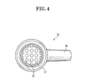
- FIGS. 2 to 4 show the auxiliary cleaning tool 21, 31 being connected to the vacuum cleaner 1. More specifically, FIG. 2 shows a tubular brush 21, with bristles 22 planted along the circumference of the end thereof. The brush 21 is connected to the end of the grip 17, after the main cleaning tool 11 is separated from the grip 17.
- FIG. 3 shows another brush 31 having a bell-shaped casing 33.
- suction ports 35 formed in the bottom side.
- bristles 37 which surround the area where the suction ports 35 are formed.
- connecting portion 39 protruding outward from the outer side of the casing 33.
- the brush 31 is also easily connected to the end of the grip 17, after the main cleaning tool 11 is separated from the grip 17.
- auxiliary cleaning tools 21, 31, which are selectively connectible to the vacuum cleaner 1 are useful in many ways as stated above, they are not suitable for cleaning dust and dirt from the hairy objects such as fur coat or carpet.
- User may press the fur coat or carpet under the brush 21, 31 and rub the bristles 22, 37 into the hairs of fur coat or carpet, and then, foreign substance or dust are exposed from within the hairs and drawn into the cleaner.
- the problem is, the fur coat or carpet, being excessively delicate, is easily damaged or worn out by the suction force of the vacuum cleaner and the friction with the bristles 22, 37, and even worse, the expensive fur coat or carpet is permanently damaged as some hairs are pulled up.
- an auxiliary cleaning tool of a vacuum cleaner capable of completely removing foreign substance or dust from the hairy object such as a fur coat or a carpet, with arranging the hairs of the object neatly and maintaining the quality of the hairs at a satisfactory extent.
- an auxiliary cleaning tool of a vacuum cleaner includes a stationary body, formed as a hollow cylinder, which is removably connected to an end of a suction hose assembly connected to a cleaner body, the stationary body having a plurality of suction holes formed therealong, a brush member having a plurality of bristles protruding outwards between the respective suction holes of the stationary body, and a means for removably connecting the brush member with respect to the stationary body.
- the stationary body is formed in a bar shape.
- the plurality of suction holes are arranged along the length of the bar type stationary body in parallel relation.
- the brush member is provided with plural bristles arranged on the outer surface of the stationary body in parallel relation with the respective suction holes formed therebetween.
- the means for connecting the brush member includes a rotary body disposed between the stationary body and the brush member to be capable of rotating with respect to the stationary body, the rotary body having a plurality of openings corresponding to the plurality of the suction holes, and a sliding groove portion provided between the plurality of openings on the outer surface of the rotary body, for a sliding-connection of the brush member.
- the means for connecting the brush member further includes a means for supporting the rotation of the rotary body with respect to the stationary body in a manner of preventing separation.
- the means for supporting the rotation includes a supporting rib protruding outwards from a connecting portion of the stationary body in a radial direction, and a supporting cap connected to an opposite end with respect to the connecting portion of the stationary body, facing the supporting rib.
- the means for connecting the brush member may be constructed in a simpler structure, by including a sliding groove portion provided in parallel relation with the plurality of suction holes on the circumference of the stationary body, for sliding-connecting the brush member from which the plurality of bristles protrude in single file.
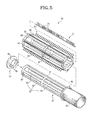
- FIG. 5 is an exploded perspective view of an auxiliary cleaning tool of a vacuum cleaner according to the present invention
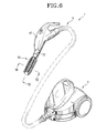
- FIG. 6 is a perspective view illustrating the auxiliary cleaning tool being assembled with the vacuum cleaner.
- the auxiliary cleaning tool 50 includes a stationary body 51 selectively connectible to a suction hose assembly 9, a rotary body 61 rotatably connected with respect to the stationary body 51, and a brush member 71 removably connected to the rotary body 61. Further provided is a supporting cap 81 for rotatably supporting the rotary body 61 with respect to the outer surface of the stationary body 51.
- the stationary body 51 may be formed as a hollow cylinder, mainly divided into a rotation supporting portion 52 that rotatably supports the rotary body 61 and a connecting portion 55 that connects to the suction hose assembly 9.
- the rotation supporting portion 52 being formed on larger area of the stationary body 51, has the smaller radius than that of the connecting portion 55.
- a supporting rib 56 protruding outward in a radial direction. The supporting rib 56 serves to support relative rotation of the rotary body 61 with respect to the stationary body 51 by the cooperation with the supporting cap 81 which will be described later.
- the rotary body 61 in cylindrical shape is connected to the external surface of the rotation supporting portion 52 to be capable of relative-rotating.
- the openings 64 permit dust and dirt from outside drawing in through the suction holes 54 of the stationary body 51 during the rotation of the rotary body 61.
- the reinforcement rib 57 at the suction holes 54 there is a driving reinforcement rib 67 provided at the middle of the openings 64 in a circumferential direction.
- FIG. 7 is a sectional view taken on line VII-VII of the auxiliary cleaning tool of FIG. 6, and FIG. 8 is a sectional view taken on line VIII-VIII of the auxiliary cleaning tool of FIG. 6.
- FIG. 8 somewhat exaggerates the section of the auxiliary cleaning tool of FIG. 6.
- FIGS. 7 and 8 show the sliding groove portions in greater detail. Referring to FIGS. 7 and 8, each sliding groove portion 65 is open at one end toward the connecting portion 55 of the stationary body 51, while it 65 is closed at the other end. On the outer surface of the sliding groove portion 65 is a slit 66 cut along the length between the open end and the closed other end.
- the brush member 71 enters through the open end of the sliding groove portion 65 and then slides along the slit 66 so as to be mounted on the outer surface 63 of the rotary body 61.
- the bristles 73 are arranged at predetermined intervals, and can be fabricated integrally with the brush member 71 by injection molding.
- the bristles 73 may be, preferably but not limitedly, elastic material that is flexible enough not to damage soft and weak hairs of the object being cleaned.
- the supporting cap 81 is connected to the outer side of the rotary body 61 which is connected with the rotation supporting portion 52 of the stationary body 51 to be capable of relative-rotating.
- the supporting cap 81 may be formed in a disc shape, and provided with a connection flange 83 protruding towards the rotation supporting portion 52 to an annular shape.
- the connection flange 83 is housed in the rotation supporting portion 52, and is provided with a pair of hooks 85 facing each other at the end of the connecting flange 83.
- the pair of hooks 85 are connected with the corresponding hook holes 87 formed in the rotation supporting portion 82, and by the hooking of the hooks 85 and the hook holes 87 is the supporting cap 81 is securely connected to the stationary body 51.
- the supporting cap 81 whose circumference is extended outwards in a radial direction, corresponds to the supporting rib 56 formed on the connecting portion 55 of the stationary body 51.
- the rotary body 61 is rotatably supported on the outer surface of the rotation supporting portion 52 of the stationary body 51 between the supporting cap 81 and the supporting rib 56.
- the brush member 71 is slid-fit in the sliding groove portions 65 of the rotary body 61.
- the rotation supporting portion 52 of the stationary body 51 is housed in the rotary body 61 slid-fitted with the brush member 71.
- the brush member 71 becomes integrally rotatable with the rotary body 61 on the outer surface of the rotation supporting portion 52 of the stationary body 51.
- the supporting cap 81 is connected to the outer side of the stationary body 51, the assembling of the auxiliary cleaning tool 50 is finished.
- Such assembled auxiliary cleaning tool 50 can connect at its connecting portion 55 with the end of the suction hose assembly 9, i.e., the operating handle 17. Then by operating the vacuum generating device of the cleaner body 3, external air is drawn in through the suction holes 54 of the auxiliary cleaning tool 50. At this time, the user grabs the operating handle 17 and gets the auxiliary cleaning tool 50 to the object to be cleaned, for example, to the fur coat or carpet. As the user brushes the fur coat or carpet clean with the auxiliary cleaning tool 50, the bristles 73 of the brush member 71 get into hairs and accordingly, foreign substance or dust is let out.
- the rotary body 61 rotates on the stationary body 51, the user can brush the objects easily with the auxiliary cleaning tool 50. And foreign substance or dust jumps out of hairs, and is drawn in through the suction holes 54 of the auxiliary cleaning tool 50. As a result, the fur coat or carpet can be cleaned effectively, while it is also tidied orderly.
- the auxiliary cleaning tool 50 may be disassembled in reverse order to the assembling order. Then hairs in the bristles 73 are manually taken, or washed off. Washing is preferable, because it will remove the dirt together with hairs.
- the brush member 71 and particularly, the bristles 73 may be worn out or deformed as time lapses, or due to external impact.
- the present invention can be efficient in this respect, because according to the present invention, the brush member 71 in question can be taken out and replaced with a new one.
- the above-described preferred embodiment has depicted the auxiliary cleaning tool 50 having the brush member 71 being connected to the rotary body 61 in a manner of being integrally rotatable with respect to the outer surface of the stationary body 51.
- the brush member 71 may be removably attached to the outer surface of the stationary body 51 in the absence of the rotary body 61
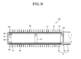
- FIG. 9 illustrates the auxiliary cleaning tool adopting such construction as another preferred embodiment.
- the auxiliary cleaning tool 100 includes sliding groove portions 105 formed between the respective suction holes 54 along the length of the outer surface of the stationary body 51.
- Each sliding groove portion 105 is open at an opposite end with respect to the connecting portion 55, and is provided with a slit 106 cut in the outer surface along the lengthwise direction thereof.
- the brush member 70 can be removably connected on the outer surface of the stationary body 51, i.e., through the opening of the sliding groove portions 105.
- Comparing the second embodiment with the first embodiment will give only one difference that the brush member 70 is not rotatable with respect to the surface to be cleaned in the second embodiment.
- the second embodiment also achieves the same aspect and effect as that of the first embodiment.
- the second embodiment requiring simpler construction may be more preferable at least in terms of cost-effectiveness.
- the user of the cleaner can clean hairy objects with tying the same because the foreign substance or dust can be completely removed. Furthermore, hairs of usually expensive objects such as fur coat or carpet remain intact during the cleaning process.
Landscapes
- Engineering & Computer Science (AREA)
- Mechanical Engineering (AREA)
- Manufacturing & Machinery (AREA)
- Nozzles For Electric Vacuum Cleaners (AREA)
Abstract
Description
Claims (5)
- An auxiliary cleaning tool of a vacuum cleaner, comprising:a stationary body, formed as a hollow cylinder, which is removably connected to an end of a suction hose assembly connected to a cleaner body, the stationary body having a plurality of suction holes formed therealong;a brush member having a plurality of bristles protruding outwards between the respective suction holes of the stationary body; anda means for removably connecting the brush member with respect to the stationary body.
- The auxiliary cleaning tool of claim 1, wherein
the stationary body is formed in a bar shape;
the plurality of suction holes are arranged along the length of the bar type stationary body in parallel relation; and
the brush member is provided with plural bristles arranged on the outer surface of the stationary body in parallel relation with the respective suction holes formed therebetween. - The auxiliary cleaning tool of claim 1 or 2, wherein the means for connecting the brush member comprises:a rotary body disposed between the stationary body and the brush member to be capable of rotating with respect to the stationary body, the rotary body having a plurality of openings corresponding to the plurality of the suction holes; anda sliding groove portion provided between the plurality of openings on the outer surface of the rotary body, for a sliding-connection of the brush member.
- The auxiliary cleaning tool of claim 3, further comprising a means for supporting the rotation of the rotary body with respect to the stationary body in a manner of preventing separation, wherein
the means for supporting the rotation comprises,
a supporting rib protruding outwards from a connecting portion of the stationary body in a radial direction, and
a supporting cap connected to an opposite end with respect to the connecting portion of the stationary body, facing the supporting rib. - The auxiliary cleaning tool of claim 1 or claim 2, wherein the means for connecting the brush member comprises a sliding groove portion provided in parallel relation with the plurality of suction holes on the circumference of the stationary body, for sliding-connecting the brush member from which the plurality of bristles protrude in single file.
Applications Claiming Priority (2)
| Application Number | Priority Date | Filing Date | Title |
|---|---|---|---|
| KR10-2003-0011115A KR100507924B1 (en) | 2003-02-21 | 2003-02-21 | Auxiliary cleaning tool of vacuum cleaner |
| KR2003011115 | 2003-02-21 |
Publications (2)
| Publication Number | Publication Date |
|---|---|
| EP1449473A2 true EP1449473A2 (en) | 2004-08-25 |
| EP1449473A3 EP1449473A3 (en) | 2005-11-09 |
Family
ID=27656474
Family Applications (1)
| Application Number | Title | Priority Date | Filing Date |
|---|---|---|---|
| EP03009199A Withdrawn EP1449473A3 (en) | 2003-02-21 | 2003-04-22 | Auxiliary cleaning tool of vacuum cleaner |
Country Status (3)
| Country | Link |
|---|---|
| EP (1) | EP1449473A3 (en) |
| KR (1) | KR100507924B1 (en) |
| RU (1) | RU2263458C2 (en) |
Cited By (6)
| Publication number | Priority date | Publication date | Assignee | Title |
|---|---|---|---|---|
| CN102370442A (en) * | 2010-08-17 | 2012-03-14 | 珍巴多工业股份有限公司 | Suction Nozzle Used For Electric Cleaner |
| CN102475522A (en) * | 2010-11-29 | 2012-05-30 | 大连洪信国际贸易有限公司 | Vacuum cleaner with a vacuum cleaner head |
| CN102599856A (en) * | 2011-01-24 | 2012-07-25 | 珍巴多工业股份有限公司 | Suction nozzle for electric vacuum cleaner |
| EP2813168A1 (en) * | 2013-06-12 | 2014-12-17 | Samsung Electronics Co., Ltd | Vacuum cleaner |
| CN112315371A (en) * | 2019-08-05 | 2021-02-05 | 必胜公司 | Vacuum cleaner auxiliary tool |
| US11064854B2 (en) | 2016-05-31 | 2021-07-20 | Darius Development Limited | Cleaner attachment device |
Families Citing this family (2)
| Publication number | Priority date | Publication date | Assignee | Title |
|---|---|---|---|---|
| RU2573287C1 (en) * | 2015-02-06 | 2016-01-20 | Марат Мунирович Шакиров | Suction nozzle of vacuum cleaner |
| RU2607430C1 (en) * | 2015-12-25 | 2017-01-10 | Марат Мунирович Шакиров | Vacuum cleaner suction fitting |
Family Cites Families (12)
| Publication number | Priority date | Publication date | Assignee | Title |
|---|---|---|---|---|
| US2243120A (en) * | 1938-11-14 | 1941-05-27 | Chester R Pollitt | Attachment for vacuum cleaners |
| US2277444A (en) * | 1940-05-20 | 1942-03-24 | Mcphee Margaret Elizabeth | Cleaning implement for venetian blinds and the like |
| US2606338A (en) * | 1949-01-13 | 1952-08-12 | Ellen Friscoe | Vacuum cleaning brush, including removable bristle holding cores |
| US2811738A (en) * | 1953-12-16 | 1957-11-05 | Singer Mfg Co | Radiator tool and brush combinations for vacuum cleaners |
| US2821736A (en) * | 1954-04-13 | 1958-02-04 | Royal Appliance Mfg | Suction brush for venetian blinds |
| GB2076640A (en) * | 1980-05-09 | 1981-12-09 | Wessel Hans | Vacuum cleaner nozzles |
| US4688295A (en) * | 1985-04-05 | 1987-08-25 | Starnes Doris H | Vacuum cleaner attachment |
| DE3831953A1 (en) * | 1988-09-21 | 1990-03-29 | Juergen Kupke | Vacuum cleaner attachment |
| AU692175B2 (en) * | 1993-10-28 | 1998-06-04 | Sanyo Electric Co., Ltd. | Suction member for use with vacuum cleaner |
| DE9407163U1 (en) * | 1994-04-29 | 1994-09-22 | Schlüter, Ferdinand, 86857 Hurlach | Cleaning brush, especially for boilers, oil stoves and pipes |
| JPH10276835A (en) * | 1997-04-09 | 1998-10-20 | Kazuyo Kato | Suction brushing device |
| AU2002211207A1 (en) * | 2000-10-06 | 2002-04-15 | Arcelik, A.S. | Vacuum cleaner |
-
2003
- 2003-02-21 KR KR10-2003-0011115A patent/KR100507924B1/en not_active Expired - Fee Related
- 2003-04-22 EP EP03009199A patent/EP1449473A3/en not_active Withdrawn
- 2003-04-25 RU RU2003112284/12A patent/RU2263458C2/en not_active IP Right Cessation
Cited By (13)
| Publication number | Priority date | Publication date | Assignee | Title |
|---|---|---|---|---|
| CN102370442A (en) * | 2010-08-17 | 2012-03-14 | 珍巴多工业股份有限公司 | Suction Nozzle Used For Electric Cleaner |
| CN102370442B (en) * | 2010-08-17 | 2016-08-10 | 珍巴多工业股份有限公司 | Suction Nozzle Used For Electric Cleaner |
| CN102475522A (en) * | 2010-11-29 | 2012-05-30 | 大连洪信国际贸易有限公司 | Vacuum cleaner with a vacuum cleaner head |
| CN102599856A (en) * | 2011-01-24 | 2012-07-25 | 珍巴多工业股份有限公司 | Suction nozzle for electric vacuum cleaner |
| EP2813168A1 (en) * | 2013-06-12 | 2014-12-17 | Samsung Electronics Co., Ltd | Vacuum cleaner |
| US11064854B2 (en) | 2016-05-31 | 2021-07-20 | Darius Development Limited | Cleaner attachment device |
| EP3772311A1 (en) * | 2019-08-05 | 2021-02-10 | Bissell Inc. | Vacuum cleaner accessory tool |
| CN112315371A (en) * | 2019-08-05 | 2021-02-05 | 必胜公司 | Vacuum cleaner auxiliary tool |
| US11607101B2 (en) | 2019-08-05 | 2023-03-21 | Bissell Inc. | Vacuum cleaner accessory tool |
| CN112315371B (en) * | 2019-08-05 | 2024-11-26 | 必胜公司 | Vacuum cleaner accessories |
| CN119318448A (en) * | 2019-08-05 | 2025-01-17 | 必胜公司 | Auxiliary tool for vacuum cleaner |
| US12201252B2 (en) | 2019-08-05 | 2025-01-21 | Bissell Inc. | Vacuum cleaner accessory tool |
| CN119318448B (en) * | 2019-08-05 | 2026-04-14 | 必胜公司 | Auxiliary tool for vacuum cleaner |
Also Published As
| Publication number | Publication date |
|---|---|
| KR20040075570A (en) | 2004-08-30 |
| RU2263458C2 (en) | 2005-11-10 |
| EP1449473A3 (en) | 2005-11-09 |
| KR100507924B1 (en) | 2005-08-19 |
Similar Documents
| Publication | Publication Date | Title |
|---|---|---|
| US12453451B2 (en) | Agitator with hair removal | |
| US12207783B2 (en) | Cleaner | |
| EP1582131B1 (en) | Rotary cleaning-body, suction port body of vacuum cleaner, and production method of rotary cleaning body | |
| CA1165063A (en) | Wide-sweep carpet cleaner bristle strip and brush roll | |
| US5970577A (en) | Brush head assembly for a vacuum cleaner | |
| US5537710A (en) | Cleaning tool having split manifold | |
| JP4975981B2 (en) | Rotating rotor of floor nozzle for vacuum cleaner and electric vacuum cleaner | |
| KR100507924B1 (en) | Auxiliary cleaning tool of vacuum cleaner | |
| EP4531643B1 (en) | Agitator element for a vacuum cleaner | |
| CN111839347B (en) | High-efficiency rolling brush for dust collector and dust collector comprising same | |
| JP4176601B2 (en) | Suction port and vacuum cleaner | |
| JP4504163B2 (en) | Suction port and vacuum cleaner | |
| JPH1133510A (en) | Upright type cleaner | |
| CN216907783U (en) | Surface cleaning head for a vacuum cleaner | |
| KR20250011156A (en) | Vacuum cleaner head for vacuum cleaner | |
| JP4630148B2 (en) | Floor nozzle for vacuum cleaner and electric vacuum cleaner | |
| CN218943206U (en) | Surface cleaning device with mop assembly | |
| JP2004351147A (en) | Rotary cleaning body, suction port of vacuum cleaner, and method of manufacturing rotary cleaning body | |
| JP2001204656A (en) | Floor nozzle | |
| JP2004344345A (en) | Rotary cleaning body and suction port of vacuum cleaner | |
| JP2007268123A (en) | Rotating cleaning body and electric vacuum cleaner provided with the same | |
| KR19980045294U (en) | Auxiliary Brush for Vacuum Cleaner | |
| JPH07116089A (en) | Nozzle unit for vacuum cleaner | |
| JPH11206636A (en) | Vacuum cleaner and its suction body |
Legal Events
| Date | Code | Title | Description |
|---|---|---|---|
| PUAI | Public reference made under article 153(3) epc to a published international application that has entered the european phase |
Free format text: ORIGINAL CODE: 0009012 |
|
| 17P | Request for examination filed |
Effective date: 20030422 |
|
| AK | Designated contracting states |
Kind code of ref document: A2 Designated state(s): AT BE BG CH CY CZ DE DK EE ES FI FR GB GR HU IE IT LI LU MC NL PT RO SE SI SK TR |
|
| AX | Request for extension of the european patent |
Extension state: AL LT LV MK |
|
| PUAL | Search report despatched |
Free format text: ORIGINAL CODE: 0009013 |
|
| AK | Designated contracting states |
Kind code of ref document: A3 Designated state(s): AT BE BG CH CY CZ DE DK EE ES FI FR GB GR HU IE IT LI LU MC NL PT RO SE SI SK TR |
|
| AX | Request for extension of the european patent |
Extension state: AL LT LV MK |
|
| STAA | Information on the status of an ep patent application or granted ep patent |
Free format text: STATUS: THE APPLICATION HAS BEEN WITHDRAWN |
|
| 18W | Application withdrawn |
Effective date: 20060411 |