EP1448977B1 - Method and system for characterising spray plumes - Google Patents
Method and system for characterising spray plumes Download PDFInfo
- Publication number
- EP1448977B1 EP1448977B1 EP02779072A EP02779072A EP1448977B1 EP 1448977 B1 EP1448977 B1 EP 1448977B1 EP 02779072 A EP02779072 A EP 02779072A EP 02779072 A EP02779072 A EP 02779072A EP 1448977 B1 EP1448977 B1 EP 1448977B1
- Authority
- EP
- European Patent Office
- Prior art keywords
- plume
- spray
- spray plume
- imaging
- light
- Prior art date
- Legal status (The legal status is an assumption and is not a legal conclusion. Google has not performed a legal analysis and makes no representation as to the accuracy of the status listed.)
- Expired - Lifetime
Links
- 239000007921 spray Substances 0.000 title claims abstract description 127
- 238000000034 method Methods 0.000 title claims description 16
- 238000003384 imaging method Methods 0.000 claims abstract description 34
- 239000000443 aerosol Substances 0.000 claims abstract description 27
- 238000005286 illumination Methods 0.000 claims description 12
- 230000001427 coherent effect Effects 0.000 claims description 2
- 239000003814 drug Substances 0.000 description 9
- 229940079593 drug Drugs 0.000 description 7
- 238000012512 characterization method Methods 0.000 description 6
- 240000007320 Pinus strobus Species 0.000 description 5
- 238000009472 formulation Methods 0.000 description 5
- 239000000203 mixture Substances 0.000 description 5
- 230000004913 activation Effects 0.000 description 4
- 238000012360 testing method Methods 0.000 description 3
- 238000009432 framing Methods 0.000 description 2
- 238000002347 injection Methods 0.000 description 2
- 239000007924 injection Substances 0.000 description 2
- NOESYZHRGYRDHS-UHFFFAOYSA-N insulin Chemical compound N1C(=O)C(NC(=O)C(CCC(N)=O)NC(=O)C(CCC(O)=O)NC(=O)C(C(C)C)NC(=O)C(NC(=O)CN)C(C)CC)CSSCC(C(NC(CO)C(=O)NC(CC(C)C)C(=O)NC(CC=2C=CC(O)=CC=2)C(=O)NC(CCC(N)=O)C(=O)NC(CC(C)C)C(=O)NC(CCC(O)=O)C(=O)NC(CC(N)=O)C(=O)NC(CC=2C=CC(O)=CC=2)C(=O)NC(CSSCC(NC(=O)C(C(C)C)NC(=O)C(CC(C)C)NC(=O)C(CC=2C=CC(O)=CC=2)NC(=O)C(CC(C)C)NC(=O)C(C)NC(=O)C(CCC(O)=O)NC(=O)C(C(C)C)NC(=O)C(CC(C)C)NC(=O)C(CC=2NC=NC=2)NC(=O)C(CO)NC(=O)CNC2=O)C(=O)NCC(=O)NC(CCC(O)=O)C(=O)NC(CCCNC(N)=N)C(=O)NCC(=O)NC(CC=3C=CC=CC=3)C(=O)NC(CC=3C=CC=CC=3)C(=O)NC(CC=3C=CC(O)=CC=3)C(=O)NC(C(C)O)C(=O)N3C(CCC3)C(=O)NC(CCCCN)C(=O)NC(C)C(O)=O)C(=O)NC(CC(N)=O)C(O)=O)=O)NC(=O)C(C(C)CC)NC(=O)C(CO)NC(=O)C(C(C)O)NC(=O)C1CSSCC2NC(=O)C(CC(C)C)NC(=O)C(NC(=O)C(CCC(N)=O)NC(=O)C(CC(N)=O)NC(=O)C(NC(=O)C(N)CC=1C=CC=CC=1)C(C)C)CC1=CN=CN1 NOESYZHRGYRDHS-UHFFFAOYSA-N 0.000 description 2
- 238000002483 medication Methods 0.000 description 2
- 239000007922 nasal spray Substances 0.000 description 2
- 229940097496 nasal spray Drugs 0.000 description 2
- 239000002245 particle Substances 0.000 description 2
- 238000005086 pumping Methods 0.000 description 2
- 241000371980 Influenza B virus (B/Shanghai/361/2002) Species 0.000 description 1
- 102000004877 Insulin Human genes 0.000 description 1
- 108090001061 Insulin Proteins 0.000 description 1
- 208000019693 Lung disease Diseases 0.000 description 1
- 208000019695 Migraine disease Diseases 0.000 description 1
- 239000012190 activator Substances 0.000 description 1
- 238000004458 analytical method Methods 0.000 description 1
- 238000013459 approach Methods 0.000 description 1
- 230000015572 biosynthetic process Effects 0.000 description 1
- 238000013461 design Methods 0.000 description 1
- 238000011161 development Methods 0.000 description 1
- 238000012377 drug delivery Methods 0.000 description 1
- 239000012530 fluid Substances 0.000 description 1
- 230000005484 gravity Effects 0.000 description 1
- 229910052736 halogen Inorganic materials 0.000 description 1
- 150000002367 halogens Chemical class 0.000 description 1
- 229940125396 insulin Drugs 0.000 description 1
- 238000005259 measurement Methods 0.000 description 1
- 206010027599 migraine Diseases 0.000 description 1
- 230000008518 non respiratory effect Effects 0.000 description 1
- 230000003287 optical effect Effects 0.000 description 1
- 230000000704 physical effect Effects 0.000 description 1
- 230000002685 pulmonary effect Effects 0.000 description 1
- 230000001105 regulatory effect Effects 0.000 description 1
- 230000000241 respiratory effect Effects 0.000 description 1
- 239000000523 sample Substances 0.000 description 1
- 230000001360 synchronised effect Effects 0.000 description 1
- 230000008685 targeting Effects 0.000 description 1
Images

Classifications
-
- G—PHYSICS
- G01—MEASURING; TESTING
- G01N—INVESTIGATING OR ANALYSING MATERIALS BY DETERMINING THEIR CHEMICAL OR PHYSICAL PROPERTIES
- G01N21/00—Investigating or analysing materials by the use of optical means, i.e. using sub-millimetre waves, infrared, visible or ultraviolet light
- G01N21/17—Systems in which incident light is modified in accordance with the properties of the material investigated
- G01N21/47—Scattering, i.e. diffuse reflection
- G01N21/49—Scattering, i.e. diffuse reflection within a body or fluid
- G01N21/53—Scattering, i.e. diffuse reflection within a body or fluid within a flowing fluid, e.g. smoke
- G01N21/538—Scattering, i.e. diffuse reflection within a body or fluid within a flowing fluid, e.g. smoke for determining atmospheric attenuation and visibility
Definitions
- the present invention relates to systems for and methods of characterizing aerosol spray plumes, more particularly, to systems and methods that illuminate an aerosol spray plume and utilize optical techniques to characterize the plume.
- a pulmonary delivery route is preferred for medicines used in the treatment of many pulmonary diseases and respiratory ailments because the dose of medication can be delivered to tissues that can more efficiently absorb the medication, thereby more readily bringing relief to patients.
- medications for non-respiratory problems such as flu vaccines, insulin and migraine relievers can also be delivered with an aerosol delivery system (ADS).
- ADS aerosol delivery system
- patients with different medical conditions present challenges respecting the safety and efficacy of the aerosol delivery system, in part due to the different physical properties of the different formulations for different medications.
- the fluid dynamic characterization of the aerosol spray of a particular medicine emitted by a metered nasal spray device is therefore crucial in determining the overall performance of the inhaler as a drug delivery device.
- Spray plume characterization is an integral part of the regulatory submissions necessary for Food and Drug Administration approval.
- the plume acts as a quick and precise indication of the overall performance of most ADS.
- drug targeting can be optimized by the appropriate choice of aerosol delivery system and formulation. Further, studies of characteristics of spray plumes from different ADSs can be used to guide product design.
- a laser generates a fan-shaped sheet of light which is aligned with, and passes through, the spray axis of a spray plume in order to illuminate a slice of the plume along the spray axis.
- a digital camera positioned to a side of the plume captures consecutive images of the slice.
- the laser is then adjusted to generate a fan-shaped sheet of light which is transverse to the spray axis in order to illuminate a transverse cross-sectional slice of a spray plume.
- the digital camera is re-positioned to a position above the plume to capture consecutive images of the transverse plume slice.
- an injection chamber into which an injection nozzle projects has four transparent side walls.
- a video camera is pointed toward one of the side walls and a screen is positioned behind the opposite side wall.
- a strobe is positioned outside one or both of the two remaining sides.
- a jet of gas is injected into the chamber and the strobe (or both strobes if there are two) is flashed synchronously with the camera and the resultant image captured. This may be repeated after a time delay.
- US4,628,465 to Ito discloses a strobe and camera on the same side of a plume.
- the plume is illuminated with the strobe as an image is taken with the camera.
- the synchronous flashing and imaging may be repeated after a time delay.
- US5,701,156 to Pierce discloses a light pipe to direct a beam of collimated light through a spray plume to a screen at one wall of an enclosure.
- a camera at an opposite wall of the enclosure views the screen.
- a similar arrangement is provided with a second camera perpendicular to the first camera in order to view the plume from a different angle.
- the density of a spray plume generated by an aerosol delivery system may be characterised by illuminating a face of the plume with light and then imaging the plume.
- the shape of the plume may be characterised by operating the ADS in a controlled manner to form a first spray plume.
- a face of the plume is illuminated and the plume imaged from a first side parallel to the spray axis of the plume.
- the ADS is then again operated in the controlled manner to form a second spray plume.
- a face of the second plume is illuminated and the second plume imaged from a second side which is parallel to the spray axis of the plume and perpendicular to the first side.
- a method of characterising a spray plume comprising: operating an aerosol delivery system to form a first spray plume; illuminating said first spray plume with light such that said light impinges upon the entirety of a face of said first spray plume; imaging said first spray plume with a camera from a first side parallel to a spray axis of said spray plume; characterised by: said operating said aerosol delivery system to form said first spray plume comprising operating said aerosol delivery system in accordance with a set of parameters; operating said aerosol delivery system in accordance with said set of parameters to form a second spray plume; illuminating said second spray plume with light such that said light impinges upon the entirety of a face of said second spray plume; imaging said second spray plume with said camera from a second side parallel to a spray axis of said spray plume, said second side being perpendicular to said first side.
- a system of characterising a spray plume comprising: an actuator for operating an aerosol delivery system to form a spray plume; a source of illumination for illuminating said spray plume with light such that said light impinges upon the entirety of a face of said spray plume; an imaging device positioned for imaging said spray plume from a side parallel to a spray axis of said aerosol delivery device; characterised by an actuator control unit programmed to operate said actuator in accordance with a set of parameters; and a turntable having a rotational axis parallel to said spray axis for rotating said aerosol delivery system.
- the spray characterization system of the present invention is capable of providing images of the time-evolution, particle distribution, divergence angle, and intrinsic plume pattern of aerosol sprays.
- the spray data characterization system is a non-intrusive system that may be adjustable and is capable of capturing and displaying information representative of the time evolution of an aerosol spray for substantially complete geometrical imaging analysis.
- the modular hardware of the system allows easy customization to meet needs of a variety of spray testing applications.
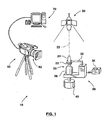
- Figure 1 show a spray data characterization system 10 that generates data representative of the characteristics of a spray plume as emitted from a spray pump 20.
- the system 10 includes a spray pump actuator 30, turntable 40, illumination device 50 and imaging device 60 connected to a processor 70.
- the spray pump 20 is designed to dispense a metered amount of medicament when a collar 23 on its nozzle 24 is compressed toward reservoir 26.
- the actuator 30 of system 10 has a reciprocating actuator arm 32 with an end overlying collar 23 .
- the actuator is designed to position the spray pump 20 so as to direct an aerosol spray dispensed from pump 20 along a spray axis 22.
- the arm 32 reciprocates in a controlled fashion, with a selectable force and stroke, when suitably prompted by actuator control unit 34.
- Actuator 30 may be an electro-mechanical transducer that converts electrical control signals from control unit 34.
- a suitable actuator is the Nasal Spray Pump Actuator sold by InnovaSystems of Pennsauken, NJ.
- the InnovaSystems actuator includes built-in programmability to control key parameters involved with aerosol spray pumping, such as pumping force and duration.
- hydraulic, pneumatic, or mechanical linkage actuators may be substituted.
- the illumination device 50 is arranged to continuously illuminate any spray plume generated by spray pump 20.
- Device 50 may emit a continuous strong conical beam of non-coherent light that is directed so as to illuminate the entire plume.
- the beam of the illumination device 50 may be centred with respect to the spray axis 22 so that the plume is more evenly illuminated. It has been found to be suitable to illuminate the plume to a brightness of 300 Watts.
- the illumination device may employ a halogen light bulb as the light source, such as Kaiser 300W probe light.
- the imaging device 60 has an imaging lens system 62 which may provide zoom (magnification) capabilities.
- Device 60 outputs images to computer 70.
- the imaging device 60 is capable of an imaging acquisition speed (i.e., framing rate) and spatial resolution sufficient to accurately capture the time evolution of a spray plume.
- the imaging device 60 may provide a framing rate in the neighbourhood of sixty frames per second (fps) at a resolution of 720X480 pixels and thirty-two bit intensity.
- Device 60 may comprise three charge coupled devices ("CCD"s) to provide colour images.
- the imaging device may be a digital camcorder such as a Canon GL1 digital camcorder.
- the processor 70 may be a general-purpose computer, such as a PC-type computer or a work station, operating under software control.
- the computer may be an Intel Pentium-based computer system running a Windows ME operating system.
- the computer has suitable I/O devices such as a keyboard, mouse, and display.
- the illumination device 50, imaging device 60 and turntable 40 may be mounted to a common platform at fixed relative positions to each other. This fixed positioning is such that, as seen in figure 2, light from the illumination device 50 impinges at a first side S1 of spray pump 20 and imaging device 60 takes images from a second side S2 of the spray pump, with side S2 being perpendicular to side S1 .
- a calibration operation is performed once, where the components are mounted to a common platform, or before each operation where the components are not in fixed relative positions.
- the calibration operation involves placing a target of known dimensions at the spray axis and then imaging this with the imaging device 60 in order to provide scale information to processor 70.
- activator control unit 34 may be programmed for a stipulated activation force and duration which is considered appropriate for the particular spray pump 20 and formulation under test. This force and duration information is passed to processor 70 (either electronically or manually) for recordal.
- the pump 20, filled with the formulation under test, is loaded into the actuator 30.
- the illumination device 50 is turned on.
- the imaging device 60 is activated, set to capture images at a suitable frame rate, and focussed on a field of view including the tip of the nozzle 24. These sequential images are passed to processor 70 for recordal.
- An activation signal is then given to the actuator via the actuator controller 34 such that arm 32 reciprocates to actuate pump 20 to spray formulation.
- the resulting time-evolving spray plume is captured by the imaging device 60 and recorded by processor 70.
- the image of the plume imaged by imaging device 60 is an image of the complete plume, collapsed into two-dimensions.
- the image will indicate the density of the plume. Recording of the spray plume may continue as long as desired in order to fully characterise the time-evolution of the plume.
- turntable 40 is used to rotate actuator 30, and hence spray pump 20, through ninety degrees. This re-orients the spray pump from its position shown in figure 2 whereat side S2 of the pump faces imaging device 60 to its position shown in figure 3 whereat side S3 of the pump faces the imaging device 60. (As will be apparent, side S3 of the pump is perpendicular to side S2 of the pump.)
- Another activation signal is then given to the actuator 30 via the actuator controller 34. This results in a second time-evolving spray plume which is generated with the same force and duration parameters as was the first spray plume.
- the second plume is captured by the imaging device 60 and recorded by the processor 70. Again, recording may continue as long as desired.
- the first and second plumes may be assumed to be identical in view of the fact that they are generated with the same parameters. Consequently, a given image of the first plume may be paired with a time-equivalent image of the second plume to provide two images of, effectively, the same plume from different angles. Since these two two-dimensional images are taken from two different sides, which sides are at ninety degrees to one another, these two-images completely characterise the three-dimensional shape of these identical plumes.
- Processor 70 may be used to provide time-equivalent image pairings for this purpose.
- any zoom feature of the lens system 62 of the imaging device 60 may be used to quantify partial characteristics of spray plumes emitted from spray pump 20. For example, precise plume angles, defined within the boundaries of travelling spray particles, can be analysed along with associated characteristics such as plume intensity and plume orientation.
- the beam of the illumination device may be adjustable in its extent. By cutting off a portion of the beam, only a portion of the spray plume may be illuminated as an alternative technique for use in quantifying partial characteristics of spray plumes emitted from the spray pump.
- the system 10 may also be used to quantify plume characteristics from full spray plume images. From inception to dissipation, full spray plume images manifest details of time evolving spray plume formation that can be sequentially visualized. Each image is representative of a characteristic pattern of the full spray plume in development at a specific time frame. Each image discloses intrinsic plume characteristics on plume intensity, two dimensional plume profile, shape of the aerosol front and plume dissipation.
- System 10 may also be used to quantify spray speed.
- the position of the travelling plume front moving along the spray axis 22 may be noted from images taken at two different times. The difference in the position of the front along the spray axis divided by the time difference yields an indication of spray speed.
- a vertically projected spray slows with time due to gravity, thus, the images chosen for measurement of spray speed are best chosen near the time of inception of the plume.
- Turntable 40 may be rotated manually or by a suitable activation signal, optionally from processor 70.
- system 10 has been described in conjunction with a spray pump as the ADS, obviously system 10 may be modified for use with any ADS.
Landscapes
- Physics & Mathematics (AREA)
- Health & Medical Sciences (AREA)
- Life Sciences & Earth Sciences (AREA)
- Chemical & Material Sciences (AREA)
- Analytical Chemistry (AREA)
- Biochemistry (AREA)
- General Health & Medical Sciences (AREA)
- General Physics & Mathematics (AREA)
- Immunology (AREA)
- Pathology (AREA)
- Containers And Packaging Bodies Having A Special Means To Remove Contents (AREA)
- Application Of Or Painting With Fluid Materials (AREA)
- Spray Control Apparatus (AREA)
- Nozzles (AREA)
Abstract
Description
- The present invention relates to systems for and methods of characterizing aerosol spray plumes, more particularly, to systems and methods that illuminate an aerosol spray plume and utilize optical techniques to characterize the plume.
- A pulmonary delivery route is preferred for medicines used in the treatment of many pulmonary diseases and respiratory ailments because the dose of medication can be delivered to tissues that can more efficiently absorb the medication, thereby more readily bringing relief to patients. In addition, medications for non-respiratory problems such as flu vaccines, insulin and migraine relievers can also be delivered with an aerosol delivery system (ADS). However, patients with different medical conditions present challenges respecting the safety and efficacy of the aerosol delivery system, in part due to the different physical properties of the different formulations for different medications. The fluid dynamic characterization of the aerosol spray of a particular medicine emitted by a metered nasal spray device is therefore crucial in determining the overall performance of the inhaler as a drug delivery device.
- Spray plume characterization is an integral part of the regulatory submissions necessary for Food and Drug Administration approval. The plume acts as a quick and precise indication of the overall performance of most ADS. Most importantly, drug targeting can be optimized by the appropriate choice of aerosol delivery system and formulation. Further, studies of characteristics of spray plumes from different ADSs can be used to guide product design.
- One approach to spray plume characterisation is described in
WO 01/13092 - While this system provides characteristics of the plume, the plume is not fully characterised and it would be advantageous to have a system which provided fuller information on the characteristics of the plume.
- In
DE199 04 319 to Homburg , an injection chamber into which an injection nozzle projects has four transparent side walls. A video camera is pointed toward one of the side walls and a screen is positioned behind the opposite side wall. A strobe is positioned outside one or both of the two remaining sides. A jet of gas is injected into the chamber and the strobe (or both strobes if there are two) is flashed synchronously with the camera and the resultant image captured. This may be repeated after a time delay. -
US4,628,465 to Ito discloses a strobe and camera on the same side of a plume. The plume is illuminated with the strobe as an image is taken with the camera. The synchronous flashing and imaging may be repeated after a time delay. -
US5,701,156 to Pierce discloses a light pipe to direct a beam of collimated light through a spray plume to a screen at one wall of an enclosure. A camera at an opposite wall of the enclosure views the screen. A similar arrangement is provided with a second camera perpendicular to the first camera in order to view the plume from a different angle. - The density of a spray plume generated by an aerosol delivery system ("ADS") may be characterised by illuminating a face of the plume with light and then imaging the plume. The shape of the plume may be characterised by operating the ADS in a controlled manner to form a first spray plume. A face of the plume is illuminated and the plume imaged from a first side parallel to the spray axis of the plume. The ADS is then again operated in the controlled manner to form a second spray plume. A face of the second plume is illuminated and the second plume imaged from a second side which is parallel to the spray axis of the plume and perpendicular to the first side.
- According to the present invention, there is provided a method of characterising a spray plume, comprising: operating an aerosol delivery system to form a first spray plume; illuminating said first spray plume with light such that said light impinges upon the entirety of a face of said first spray plume; imaging said first spray plume with a camera from a first side parallel to a spray axis of said spray plume; characterised by: said operating said aerosol delivery system to form said first spray plume comprising operating said aerosol delivery system in accordance with a set of parameters; operating said aerosol delivery system in accordance with said set of parameters to form a second spray plume; illuminating said second spray plume with light such that said light impinges upon the entirety of a face of said second spray plume; imaging said second spray plume with said camera from a second side parallel to a spray axis of said spray plume, said second side being perpendicular to said first side.
- According another aspect of the present invention, there is provided a system of characterising a spray plume, comprising: an actuator for operating an aerosol delivery system to form a spray plume; a source of illumination for illuminating said spray plume with light such that said light impinges upon the entirety of a face of said spray plume; an imaging device positioned for imaging said spray plume from a side parallel to a spray axis of said aerosol delivery device; characterised by an actuator control unit programmed to operate said actuator in accordance with a set of parameters; and a turntable having a rotational axis parallel to said spray axis for rotating said aerosol delivery system.
- In the figures which illustrate example embodiments,
- figure 1 is a perspective view of a system made in accordance with this invention,
- figures 2 and 3 are schematic plan views of the system of figure 1 which illustrate an aspect of the operation of the system.
- The spray characterization system of the present invention is capable of providing images of the time-evolution, particle distribution, divergence angle, and intrinsic plume pattern of aerosol sprays. The spray data characterization system is a non-intrusive system that may be adjustable and is capable of capturing and displaying information representative of the time evolution of an aerosol spray for substantially complete geometrical imaging analysis. The modular hardware of the system allows easy customization to meet needs of a variety of spray testing applications.
- Figure 1 show a spray
data characterization system 10 that generates data representative of the characteristics of a spray plume as emitted from aspray pump 20. Thesystem 10 includes aspray pump actuator 30,turntable 40,illumination device 50 andimaging device 60 connected to aprocessor 70. As is typical, thespray pump 20 is designed to dispense a metered amount of medicament when acollar 23 on itsnozzle 24 is compressed towardreservoir 26. - The
actuator 30 ofsystem 10 has a reciprocatingactuator arm 32 with anend overlying collar 23. The actuator is designed to position thespray pump 20 so as to direct an aerosol spray dispensed frompump 20 along aspray axis 22. Thearm 32 reciprocates in a controlled fashion, with a selectable force and stroke, when suitably prompted byactuator control unit 34.Actuator 30 may be an electro-mechanical transducer that converts electrical control signals fromcontrol unit 34. In this regard, a suitable actuator is the Nasal Spray Pump Actuator sold by InnovaSystems of Pennsauken, NJ. The InnovaSystems actuator includes built-in programmability to control key parameters involved with aerosol spray pumping, such as pumping force and duration. In alternative embodiments, hydraulic, pneumatic, or mechanical linkage actuators may be substituted. - The
illumination device 50 is arranged to continuously illuminate any spray plume generated byspray pump 20.Device 50 may emit a continuous strong conical beam of non-coherent light that is directed so as to illuminate the entire plume. The beam of theillumination device 50 may be centred with respect to thespray axis 22 so that the plume is more evenly illuminated. It has been found to be suitable to illuminate the plume to a brightness of 300 Watts. The illumination device may employ a halogen light bulb as the light source, such as Kaiser 300W probe light. - The
imaging device 60 has animaging lens system 62 which may provide zoom (magnification) capabilities.Device 60 outputs images tocomputer 70. Ideally, theimaging device 60 is capable of an imaging acquisition speed (i.e., framing rate) and spatial resolution sufficient to accurately capture the time evolution of a spray plume. For example, theimaging device 60 may provide a framing rate in the neighbourhood of sixty frames per second (fps) at a resolution of 720X480 pixels and thirty-two bit intensity.Device 60 may comprise three charge coupled devices ("CCD"s) to provide colour images. Suitably, the imaging device may be a digital camcorder such as a Canon GL1 digital camcorder. - The
processor 70 may be a general-purpose computer, such as a PC-type computer or a work station, operating under software control. For example, the computer may be an Intel Pentium-based computer system running a Windows ME operating system. The computer has suitable I/O devices such as a keyboard, mouse, and display. - Optionally, the
illumination device 50,imaging device 60 andturntable 40 may be mounted to a common platform at fixed relative positions to each other. This fixed positioning is such that, as seen in figure 2, light from theillumination device 50 impinges at a first side S1 ofspray pump 20 andimaging device 60 takes images from a second side S2 of the spray pump, with side S2 being perpendicular to side S1. - A calibration operation is performed once, where the components are mounted to a common platform, or before each operation where the components are not in fixed relative positions. The calibration operation involves placing a target of known dimensions at the spray axis and then imaging this with the
imaging device 60 in order to provide scale information toprocessor 70. - In operation,
activator control unit 34 may be programmed for a stipulated activation force and duration which is considered appropriate for theparticular spray pump 20 and formulation under test. This force and duration information is passed to processor 70 (either electronically or manually) for recordal. Thepump 20, filled with the formulation under test, is loaded into theactuator 30. Theillumination device 50 is turned on. Theimaging device 60 is activated, set to capture images at a suitable frame rate, and focussed on a field of view including the tip of thenozzle 24. These sequential images are passed toprocessor 70 for recordal. - An activation signal is then given to the actuator via the
actuator controller 34 such thatarm 32 reciprocates to actuatepump 20 to spray formulation. The resulting time-evolving spray plume is captured by theimaging device 60 and recorded byprocessor 70. In this regard, it will be noted that because light from the illumination device impinges upon the entirety of side S1 of the spray plume, the entire plume is illuminated. In consequence, the image of the plume imaged by imagingdevice 60 is an image of the complete plume, collapsed into two-dimensions. Thus, the image will indicate the density of the plume. Recording of the spray plume may continue as long as desired in order to fully characterise the time-evolution of the plume. Once this recording is complete,turntable 40 is used to rotateactuator 30, and hence spraypump 20, through ninety degrees. This re-orients the spray pump from its position shown in figure 2 whereat side S2 of the pump facesimaging device 60 to its position shown in figure 3 whereat side S3 of the pump faces theimaging device 60. (As will be apparent, side S3 of the pump is perpendicular to side S2 of the pump.) Another activation signal is then given to theactuator 30 via theactuator controller 34. This results in a second time-evolving spray plume which is generated with the same force and duration parameters as was the first spray plume. The second plume is captured by theimaging device 60 and recorded by theprocessor 70. Again, recording may continue as long as desired. - The first and second plumes may be assumed to be identical in view of the fact that they are generated with the same parameters. Consequently, a given image of the first plume may be paired with a time-equivalent image of the second plume to provide two images of, effectively, the same plume from different angles. Since these two two-dimensional images are taken from two different sides, which sides are at ninety degrees to one another, these two-images completely characterise the three-dimensional shape of these identical plumes.
Processor 70 may be used to provide time-equivalent image pairings for this purpose. - Any zoom feature of the
lens system 62 of theimaging device 60 may be used to quantify partial characteristics of spray plumes emitted fromspray pump 20. For example, precise plume angles, defined within the boundaries of travelling spray particles, can be analysed along with associated characteristics such as plume intensity and plume orientation. Optionally, and as illustrated for theillumination device 50 of figure 1, the beam of the illumination device may be adjustable in its extent. By cutting off a portion of the beam, only a portion of the spray plume may be illuminated as an alternative technique for use in quantifying partial characteristics of spray plumes emitted from the spray pump. - The
system 10 may also be used to quantify plume characteristics from full spray plume images. From inception to dissipation, full spray plume images manifest details of time evolving spray plume formation that can be sequentially visualized. Each image is representative of a characteristic pattern of the full spray plume in development at a specific time frame. Each image discloses intrinsic plume characteristics on plume intensity, two dimensional plume profile, shape of the aerosol front and plume dissipation. -
System 10 may also be used to quantify spray speed. For example, the position of the travelling plume front moving along thespray axis 22 may be noted from images taken at two different times. The difference in the position of the front along the spray axis divided by the time difference yields an indication of spray speed. Obviously, a vertically projected spray slows with time due to gravity, thus, the images chosen for measurement of spray speed are best chosen near the time of inception of the plume. -
Turntable 40 may be rotated manually or by a suitable activation signal, optionally fromprocessor 70. - While the
system 10 has been described in conjunction with a spray pump as the ADS, obviouslysystem 10 may be modified for use with any ADS. - The present embodiments are to be considered as illustrative and not restrictive, the scope of the invention being indicated by the appended claims.
Claims (11)
- A method of characterising a spray plume, comprising:operating an aerosol delivery system (20) to form a first spray plume;illuminating said first spray plume with light such that said light impinges upon the entirety of a face of said first spray plume;imaging said first spray plume with a camera (60) from a first side parallel to a spray -axis of said first spray plume;characterised by:said operating said aerosol delivery system (20) to form said first spray plume comprising operating said aerosol delivery system in accordance with a set of parameters;operating said aerosol delivery system in accordance with said set of parameters to form a second spray plume;illuminating said second spray plume with light such that said light impinges upon the entirety of a face of said second spray plume;imaging said second spray plume with said camera (60) from a second side parallel to a spray axis of said second spray plume, said second side being perpendicular to said first side.
- The method of claim 1 wherein said light is non-coherent.
- The method of claim 1 wherein said imaging said first spray plume captures at least two images of said first spray plume.
- The method of claim 3 wherein said at least two images are separated in time by a known interval and further comprising determining a speed of said spray plume from said at least two images and said known interval.
- The method of claim 3 wherein one of said images is a magnified image of a portion of said first spray plume at an outer boundary of said first spray plume.
- The method of claim 3 wherein said imaging said second spray plume captures at least two images of said second spray plume and further comprising matching an image of said first spray plume with a time-equivalent image of said second spray plume.
- The method of claim 1 wherein each said imaging is colour imaging.
- The method of claim 1 wherein said illuminating a first spray plume illuminates a side of said spray plume.
- The method of claim 1 wherein said illuminating a first spray plume illuminates a side of said first spray plume perpendicular to said first side.
- The method of claim 9 wherein said illuminating a second spray plume illuminates a side of said second spray plume perpendicular to said second side.
- A system for characterising a spray plume, comprising:an actuator (30) for operating an aerosol delivery system (20) to form a spray plume;a source of illumination (50) for illuminating said spray plume with light such that said light impinges upon the entirety of a face of said spray plume;an imaging device (60) positioned for imaging said spray plume from a side parallel to a spray axis of said aerosol delivery device;characterised byan actuator control unit (34) programmed to operate said actuator in accordance with a set of parameters; anda turntable (40) having a rotational axis parallel to said spray axis for rotating said aerosol delivery system.
Applications Claiming Priority (3)
| Application Number | Priority Date | Filing Date | Title |
|---|---|---|---|
| US991684 | 2001-11-26 | ||
| US09/991,684 US6618127B2 (en) | 2001-11-26 | 2001-11-26 | Spray plume characterization system |
| PCT/CA2002/001766 WO2003046525A1 (en) | 2001-11-26 | 2002-11-19 | Method and system for characterizing spray plume |
Publications (2)
| Publication Number | Publication Date |
|---|---|
| EP1448977A1 EP1448977A1 (en) | 2004-08-25 |
| EP1448977B1 true EP1448977B1 (en) | 2008-01-23 |
Family
ID=25537456
Family Applications (1)
| Application Number | Title | Priority Date | Filing Date |
|---|---|---|---|
| EP02779072A Expired - Lifetime EP1448977B1 (en) | 2001-11-26 | 2002-11-19 | Method and system for characterising spray plumes |
Country Status (6)
| Country | Link |
|---|---|
| US (1) | US6618127B2 (en) |
| EP (1) | EP1448977B1 (en) |
| AT (1) | ATE384943T1 (en) |
| AU (1) | AU2002342472A1 (en) |
| DE (1) | DE60224825T2 (en) |
| WO (1) | WO2003046525A1 (en) |
Families Citing this family (12)
| Publication number | Priority date | Publication date | Assignee | Title |
|---|---|---|---|---|
| US6785400B1 (en) * | 1999-08-17 | 2004-08-31 | Image Therm Engineering, Inc. | Spray data acquisition system |
| WO2003000429A2 (en) * | 2001-06-21 | 2003-01-03 | Image Therm Engineering, Inc. | Precise position controlled actuating method and system |
| US20050023368A1 (en) * | 2003-01-24 | 2005-02-03 | S.C. Johnson & Son, Inc. | Method of designing improved spray dispenser assemblies |
| US7100839B2 (en) * | 2003-04-14 | 2006-09-05 | Image Therm Engineering, Inc. | Method of servicing companies associated with a spray device operating under guidelines of a regulatory body |
| JP2010509591A (en) * | 2006-11-10 | 2010-03-25 | プロヴェリス・サイエンティフィック・コーポレーション | Automatic nasal spray pump test |
| FR2956210B1 (en) * | 2010-02-10 | 2012-06-15 | Valois Sas | MACHINE AND METHOD FOR CONTROLLING SPRAY FOR MOUNTING CHAIN OF FLUID SPRAY DEVICES. |
| US8351780B2 (en) * | 2011-02-01 | 2013-01-08 | Hamilton Sundstrand Corporation | Imaging system for hollow cone spray |
| WO2016004103A1 (en) | 2014-06-30 | 2016-01-07 | Proveris Scientific Company | Sampling apparatus for determining the amount and uniformity of a delivered dose of drug related methods |
| EP3426329A4 (en) | 2016-03-09 | 2019-11-13 | Proveris Scientific Corporation | METHODS FOR MEASURING INITIAL DOSE CONTENT UNIFORMITY YIELD RATE AND NASAL DEVICES |
| GB201700727D0 (en) * | 2017-01-16 | 2017-03-01 | Teva Pharma | Inhalers and airflow adaptors therefor |
| CN116583316A (en) | 2020-10-15 | 2023-08-11 | 普罗沃锐斯科学有限公司 | Systems and methods for inhaler testing |
| CN117664792B (en) * | 2024-01-31 | 2024-04-30 | 哈尔滨工业大学 | Device and method for tomographic reconstruction of three-dimensional density distribution |
Family Cites Families (7)
| Publication number | Priority date | Publication date | Assignee | Title |
|---|---|---|---|---|
| US4136950A (en) * | 1976-11-08 | 1979-01-30 | Labrum Engineering, Inc. | Microscope system for observing moving particles |
| JPS60104205A (en) | 1983-11-10 | 1985-06-08 | Nippon Denso Co Ltd | Method and device for measuring shape of jet body |
| US5396333A (en) * | 1992-05-21 | 1995-03-07 | General Electric Company | Device and method for observing and analyzing a stream of material |
| US5701156A (en) * | 1995-05-24 | 1997-12-23 | Pierce; James A. | Apparatus for observing the dispersion pattern of the spray plume of a spray nozzle |
| US6404494B1 (en) * | 1998-12-22 | 2002-06-11 | University Of Washington | Measurement of the lidar ratio for atmospheric aerosols using a 180 degree-backscatter nephelometer |
| DE19904319A1 (en) | 1999-01-28 | 2000-08-03 | Volkswagen Ag | Pressure chamber test system for investigating combustion engine injection processes has high-resolution camera coupled to signal control unit and whose images are digitised, recorded |
| ATE438844T1 (en) | 1999-08-17 | 2009-08-15 | Proveris Scient Corp | METHOD FOR COLLECTING DATA FROM A SPRAY |
-
2001
- 2001-11-26 US US09/991,684 patent/US6618127B2/en not_active Expired - Fee Related
-
2002
- 2002-11-19 EP EP02779072A patent/EP1448977B1/en not_active Expired - Lifetime
- 2002-11-19 AU AU2002342472A patent/AU2002342472A1/en not_active Abandoned
- 2002-11-19 AT AT02779072T patent/ATE384943T1/en not_active IP Right Cessation
- 2002-11-19 WO PCT/CA2002/001766 patent/WO2003046525A1/en not_active Ceased
- 2002-11-19 DE DE60224825T patent/DE60224825T2/en not_active Expired - Lifetime
Also Published As
| Publication number | Publication date |
|---|---|
| US6618127B2 (en) | 2003-09-09 |
| WO2003046525A1 (en) | 2003-06-05 |
| ATE384943T1 (en) | 2008-02-15 |
| HK1067899A1 (en) | 2005-04-22 |
| AU2002342472A1 (en) | 2003-06-10 |
| EP1448977A1 (en) | 2004-08-25 |
| US20030098968A1 (en) | 2003-05-29 |
| DE60224825D1 (en) | 2008-03-13 |
| DE60224825T2 (en) | 2009-01-22 |
Similar Documents
| Publication | Publication Date | Title |
|---|---|---|
| US7672478B2 (en) | Spray data acquisition system | |
| US6618127B2 (en) | Spray plume characterization system | |
| US20240102795A1 (en) | Generation of one or more edges of luminosity to form three-dimensional models of scenes | |
| US10948415B2 (en) | Method of determining surgical margins using fluorescence biopsy specimen imager | |
| US6763259B1 (en) | Surgical system supported by optical coherence tomography | |
| EP2509685B1 (en) | Object positioning with visual feedback | |
| KR101758412B1 (en) | Dental computed tomography apparatus | |
| JP5054266B2 (en) | Spray data acquisition system | |
| CN104707260A (en) | System and method for determining position of objects in radiation room for radiation therapy | |
| KR20040054791A (en) | 3d reconstruction system and method utilizing a variable x-ray source to image distance | |
| CN104684483B (en) | Fast Frame Rate Wireless Imaging | |
| JP2000513967A (en) | Distributing apparatus and operating method thereof | |
| CN107072622A (en) | X-ray imaging device and control method thereof | |
| CN106469253A (en) | Apparatus and method for display location information | |
| EP2775923A1 (en) | Systems and methods for simultaneous multi-directional imaging for capturing tomographic data | |
| CN108992796A (en) | Patient monitoring system | |
| HK1067899B (en) | Method and system for characterising spray plumes | |
| CN100382754C (en) | Digital method and apparatus for detecting bone age | |
| JPH09318523A (en) | Parameter analysis method and apparatus using the same | |
| CN223711050U (en) | A nozzle atomization testing device | |
| CN208610985U (en) | Operation navigation device | |
| CN100534388C (en) | Mammography device having a height-adjustable object platform | |
| RU167176U1 (en) | DEVICE FOR NON-INVASIVE RESEARCH OF CHARACTERISTICS OF CAPILLARIES AND CAPILLARY BLOOD | |
| JPS62274204A (en) | Microscope system for obtaining three-dimensional data | |
| JPH09166418A (en) | Position measuring device and light emitting device for position measuring |
Legal Events
| Date | Code | Title | Description |
|---|---|---|---|
| PUAI | Public reference made under article 153(3) epc to a published international application that has entered the european phase |
Free format text: ORIGINAL CODE: 0009012 |
|
| 17P | Request for examination filed |
Effective date: 20040521 |
|
| AK | Designated contracting states |
Kind code of ref document: A1 Designated state(s): AT BE BG CH CY CZ DE DK EE ES FI FR GB GR IE IT LI LU MC NL PT SE SK TR |
|
| AX | Request for extension of the european patent |
Extension state: AL LT LV MK RO SI |
|
| 17Q | First examination report despatched |
Effective date: 20050124 |
|
| REG | Reference to a national code |
Ref country code: HK Ref legal event code: DE Ref document number: 1067899 Country of ref document: HK |
|
| GRAP | Despatch of communication of intention to grant a patent |
Free format text: ORIGINAL CODE: EPIDOSNIGR1 |
|
| RTI1 | Title (correction) |
Free format text: METHOD AND SYSTEM FOR CHARACTERISING SPRAY PLUMES |
|
| GRAS | Grant fee paid |
Free format text: ORIGINAL CODE: EPIDOSNIGR3 |
|
| GRAA | (expected) grant |
Free format text: ORIGINAL CODE: 0009210 |
|
| AK | Designated contracting states |
Kind code of ref document: B1 Designated state(s): AT BE BG CH CY CZ DE DK EE ES FI FR GB GR IE IT LI LU MC NL PT SE SK TR |
|
| REG | Reference to a national code |
Ref country code: GB Ref legal event code: FG4D |
|
| REG | Reference to a national code |
Ref country code: CH Ref legal event code: EP |
|
| REG | Reference to a national code |
Ref country code: IE Ref legal event code: FG4D |
|
| REF | Corresponds to: |
Ref document number: 60224825 Country of ref document: DE Date of ref document: 20080313 Kind code of ref document: P |
|
| REG | Reference to a national code |
Ref country code: HK Ref legal event code: GR Ref document number: 1067899 Country of ref document: HK |
|
| NLV1 | Nl: lapsed or annulled due to failure to fulfill the requirements of art. 29p and 29m of the patents act | ||
| PG25 | Lapsed in a contracting state [announced via postgrant information from national office to epo] |
Ref country code: FI Free format text: LAPSE BECAUSE OF FAILURE TO SUBMIT A TRANSLATION OF THE DESCRIPTION OR TO PAY THE FEE WITHIN THE PRESCRIBED TIME-LIMIT Effective date: 20080123 Ref country code: LI Free format text: LAPSE BECAUSE OF FAILURE TO SUBMIT A TRANSLATION OF THE DESCRIPTION OR TO PAY THE FEE WITHIN THE PRESCRIBED TIME-LIMIT Effective date: 20080123 Ref country code: ES Free format text: LAPSE BECAUSE OF FAILURE TO SUBMIT A TRANSLATION OF THE DESCRIPTION OR TO PAY THE FEE WITHIN THE PRESCRIBED TIME-LIMIT Effective date: 20080504 Ref country code: CH Free format text: LAPSE BECAUSE OF FAILURE TO SUBMIT A TRANSLATION OF THE DESCRIPTION OR TO PAY THE FEE WITHIN THE PRESCRIBED TIME-LIMIT Effective date: 20080123 |
|
| REG | Reference to a national code |
Ref country code: CH Ref legal event code: PL |
|
| PG25 | Lapsed in a contracting state [announced via postgrant information from national office to epo] |
Ref country code: BG Free format text: LAPSE BECAUSE OF FAILURE TO SUBMIT A TRANSLATION OF THE DESCRIPTION OR TO PAY THE FEE WITHIN THE PRESCRIBED TIME-LIMIT Effective date: 20080423 Ref country code: AT Free format text: LAPSE BECAUSE OF FAILURE TO SUBMIT A TRANSLATION OF THE DESCRIPTION OR TO PAY THE FEE WITHIN THE PRESCRIBED TIME-LIMIT Effective date: 20080123 |
|
| ET | Fr: translation filed | ||
| PG25 | Lapsed in a contracting state [announced via postgrant information from national office to epo] |
Ref country code: BE Free format text: LAPSE BECAUSE OF FAILURE TO SUBMIT A TRANSLATION OF THE DESCRIPTION OR TO PAY THE FEE WITHIN THE PRESCRIBED TIME-LIMIT Effective date: 20080123 Ref country code: PT Free format text: LAPSE BECAUSE OF FAILURE TO SUBMIT A TRANSLATION OF THE DESCRIPTION OR TO PAY THE FEE WITHIN THE PRESCRIBED TIME-LIMIT Effective date: 20080623 |
|
| PG25 | Lapsed in a contracting state [announced via postgrant information from national office to epo] |
Ref country code: SK Free format text: LAPSE BECAUSE OF FAILURE TO SUBMIT A TRANSLATION OF THE DESCRIPTION OR TO PAY THE FEE WITHIN THE PRESCRIBED TIME-LIMIT Effective date: 20080123 Ref country code: NL Free format text: LAPSE BECAUSE OF FAILURE TO SUBMIT A TRANSLATION OF THE DESCRIPTION OR TO PAY THE FEE WITHIN THE PRESCRIBED TIME-LIMIT Effective date: 20080123 Ref country code: CZ Free format text: LAPSE BECAUSE OF FAILURE TO SUBMIT A TRANSLATION OF THE DESCRIPTION OR TO PAY THE FEE WITHIN THE PRESCRIBED TIME-LIMIT Effective date: 20080123 Ref country code: DK Free format text: LAPSE BECAUSE OF FAILURE TO SUBMIT A TRANSLATION OF THE DESCRIPTION OR TO PAY THE FEE WITHIN THE PRESCRIBED TIME-LIMIT Effective date: 20080123 Ref country code: SE Free format text: LAPSE BECAUSE OF FAILURE TO SUBMIT A TRANSLATION OF THE DESCRIPTION OR TO PAY THE FEE WITHIN THE PRESCRIBED TIME-LIMIT Effective date: 20080423 |
|
| PLBE | No opposition filed within time limit |
Free format text: ORIGINAL CODE: 0009261 |
|
| STAA | Information on the status of an ep patent application or granted ep patent |
Free format text: STATUS: NO OPPOSITION FILED WITHIN TIME LIMIT |
|
| 26N | No opposition filed |
Effective date: 20081024 |
|
| PG25 | Lapsed in a contracting state [announced via postgrant information from national office to epo] |
Ref country code: EE Free format text: LAPSE BECAUSE OF FAILURE TO SUBMIT A TRANSLATION OF THE DESCRIPTION OR TO PAY THE FEE WITHIN THE PRESCRIBED TIME-LIMIT Effective date: 20080123 |
|
| PG25 | Lapsed in a contracting state [announced via postgrant information from national office to epo] |
Ref country code: MC Free format text: LAPSE BECAUSE OF NON-PAYMENT OF DUE FEES Effective date: 20081130 |
|
| PG25 | Lapsed in a contracting state [announced via postgrant information from national office to epo] |
Ref country code: CY Free format text: LAPSE BECAUSE OF FAILURE TO SUBMIT A TRANSLATION OF THE DESCRIPTION OR TO PAY THE FEE WITHIN THE PRESCRIBED TIME-LIMIT Effective date: 20080123 |
|
| PG25 | Lapsed in a contracting state [announced via postgrant information from national office to epo] |
Ref country code: IE Free format text: LAPSE BECAUSE OF NON-PAYMENT OF DUE FEES Effective date: 20081119 |
|
| PGFP | Annual fee paid to national office [announced via postgrant information from national office to epo] |
Ref country code: FR Payment date: 20091202 Year of fee payment: 8 Ref country code: GB Payment date: 20091109 Year of fee payment: 8 Ref country code: IT Payment date: 20091123 Year of fee payment: 8 |
|
| PGFP | Annual fee paid to national office [announced via postgrant information from national office to epo] |
Ref country code: DE Payment date: 20091229 Year of fee payment: 8 |
|
| PG25 | Lapsed in a contracting state [announced via postgrant information from national office to epo] |
Ref country code: LU Free format text: LAPSE BECAUSE OF NON-PAYMENT OF DUE FEES Effective date: 20081119 |
|
| PG25 | Lapsed in a contracting state [announced via postgrant information from national office to epo] |
Ref country code: TR Free format text: LAPSE BECAUSE OF FAILURE TO SUBMIT A TRANSLATION OF THE DESCRIPTION OR TO PAY THE FEE WITHIN THE PRESCRIBED TIME-LIMIT Effective date: 20080123 |
|
| PG25 | Lapsed in a contracting state [announced via postgrant information from national office to epo] |
Ref country code: GR Free format text: LAPSE BECAUSE OF FAILURE TO SUBMIT A TRANSLATION OF THE DESCRIPTION OR TO PAY THE FEE WITHIN THE PRESCRIBED TIME-LIMIT Effective date: 20080424 |
|
| GBPC | Gb: european patent ceased through non-payment of renewal fee |
Effective date: 20101119 |
|
| REG | Reference to a national code |
Ref country code: FR Ref legal event code: ST Effective date: 20110801 |
|
| REG | Reference to a national code |
Ref country code: DE Ref legal event code: R119 Ref document number: 60224825 Country of ref document: DE Effective date: 20110601 Ref country code: DE Ref legal event code: R119 Ref document number: 60224825 Country of ref document: DE Effective date: 20110531 |
|
| PG25 | Lapsed in a contracting state [announced via postgrant information from national office to epo] |
Ref country code: FR Free format text: LAPSE BECAUSE OF NON-PAYMENT OF DUE FEES Effective date: 20101130 |
|
| PG25 | Lapsed in a contracting state [announced via postgrant information from national office to epo] |
Ref country code: GB Free format text: LAPSE BECAUSE OF NON-PAYMENT OF DUE FEES Effective date: 20101119 |
|
| PG25 | Lapsed in a contracting state [announced via postgrant information from national office to epo] |
Ref country code: IT Free format text: LAPSE BECAUSE OF NON-PAYMENT OF DUE FEES Effective date: 20101119 |
|
| PG25 | Lapsed in a contracting state [announced via postgrant information from national office to epo] |
Ref country code: DE Free format text: LAPSE BECAUSE OF NON-PAYMENT OF DUE FEES Effective date: 20110531 |