EP1448379B1 - Fibre-reinforced microactuator - Google Patents
Fibre-reinforced microactuator Download PDFInfo
- Publication number
- EP1448379B1 EP1448379B1 EP02792746A EP02792746A EP1448379B1 EP 1448379 B1 EP1448379 B1 EP 1448379B1 EP 02792746 A EP02792746 A EP 02792746A EP 02792746 A EP02792746 A EP 02792746A EP 1448379 B1 EP1448379 B1 EP 1448379B1
- Authority
- EP
- European Patent Office
- Prior art keywords
- microactuator
- reinforcing structure
- layer
- carrier substrate
- microactuator according
- Prior art date
- Legal status (The legal status is an assumption and is not a legal conclusion. Google has not performed a legal analysis and makes no representation as to the accuracy of the status listed.)
- Expired - Lifetime
Links
- 230000003014 reinforcing effect Effects 0.000 claims abstract description 75
- 239000000758 substrate Substances 0.000 claims abstract description 37
- 238000005452 bending Methods 0.000 claims abstract description 13
- 239000000463 material Substances 0.000 claims description 23
- 229920000642 polymer Polymers 0.000 claims description 14
- 229910052751 metal Inorganic materials 0.000 claims description 8
- 239000002184 metal Substances 0.000 claims description 8
- BASFCYQUMIYNBI-UHFFFAOYSA-N platinum Chemical compound [Pt] BASFCYQUMIYNBI-UHFFFAOYSA-N 0.000 claims description 6
- 239000002322 conducting polymer Substances 0.000 claims description 5
- 229920001940 conductive polymer Polymers 0.000 claims description 5
- 229920001577 copolymer Polymers 0.000 claims description 5
- 229910001000 nickel titanium Inorganic materials 0.000 claims description 5
- PAYRUJLWNCNPSJ-UHFFFAOYSA-N Aniline Chemical compound NC1=CC=CC=C1 PAYRUJLWNCNPSJ-UHFFFAOYSA-N 0.000 claims description 4
- 239000004593 Epoxy Substances 0.000 claims description 4
- KAESVJOAVNADME-UHFFFAOYSA-N Pyrrole Chemical compound C=1C=CNC=1 KAESVJOAVNADME-UHFFFAOYSA-N 0.000 claims description 4
- YTPLMLYBLZKORZ-UHFFFAOYSA-N Thiophene Chemical compound C=1C=CSC=1 YTPLMLYBLZKORZ-UHFFFAOYSA-N 0.000 claims description 4
- RTAQQCXQSZGOHL-UHFFFAOYSA-N Titanium Chemical compound [Ti] RTAQQCXQSZGOHL-UHFFFAOYSA-N 0.000 claims description 4
- PCHJSUWPFVWCPO-UHFFFAOYSA-N gold Chemical compound [Au] PCHJSUWPFVWCPO-UHFFFAOYSA-N 0.000 claims description 4
- 239000010931 gold Substances 0.000 claims description 4
- 229910052737 gold Inorganic materials 0.000 claims description 4
- 239000010936 titanium Substances 0.000 claims description 4
- 229910052697 platinum Inorganic materials 0.000 claims description 3
- 239000010935 stainless steel Substances 0.000 claims description 3
- 229910001220 stainless steel Inorganic materials 0.000 claims description 3
- 229910052719 titanium Inorganic materials 0.000 claims description 3
- 125000005678 ethenylene group Chemical group [H]C([*:1])=C([H])[*:2] 0.000 claims description 2
- 239000000178 monomer Substances 0.000 claims description 2
- 125000000843 phenylene group Chemical group C1(=C(C=CC=C1)*)* 0.000 claims description 2
- 229930192474 thiophene Natural products 0.000 claims description 2
- 238000010276 construction Methods 0.000 description 5
- HLXZNVUGXRDIFK-UHFFFAOYSA-N nickel titanium Chemical compound [Ti].[Ti].[Ti].[Ti].[Ti].[Ti].[Ti].[Ti].[Ti].[Ti].[Ti].[Ni].[Ni].[Ni].[Ni].[Ni].[Ni].[Ni].[Ni].[Ni].[Ni].[Ni].[Ni].[Ni].[Ni] HLXZNVUGXRDIFK-UHFFFAOYSA-N 0.000 description 3
- 229920000128 polypyrrole Polymers 0.000 description 3
- 229920000123 polythiophene Polymers 0.000 description 2
- 239000004814 polyurethane Substances 0.000 description 2
- 229920002635 polyurethane Polymers 0.000 description 2
- 229910000990 Ni alloy Inorganic materials 0.000 description 1
- 229910001069 Ti alloy Inorganic materials 0.000 description 1
- 229910045601 alloy Inorganic materials 0.000 description 1
- 239000000956 alloy Substances 0.000 description 1
- 229920006037 cross link polymer Polymers 0.000 description 1
- 230000003247 decreasing effect Effects 0.000 description 1
- 229920000767 polyaniline Polymers 0.000 description 1
- 239000002861 polymer material Substances 0.000 description 1
- 230000002787 reinforcement Effects 0.000 description 1
- 239000002904 solvent Substances 0.000 description 1
- 230000000638 stimulation Effects 0.000 description 1
- 239000000126 substance Substances 0.000 description 1
- 238000001356 surgical procedure Methods 0.000 description 1
- 230000008961 swelling Effects 0.000 description 1
Images
Classifications
-
- B—PERFORMING OPERATIONS; TRANSPORTING
- B81—MICROSTRUCTURAL TECHNOLOGY
- B81B—MICROSTRUCTURAL DEVICES OR SYSTEMS, e.g. MICROMECHANICAL DEVICES
- B81B3/00—Devices comprising flexible or deformable elements, e.g. comprising elastic tongues or membranes
- B81B3/0018—Structures acting upon the moving or flexible element for transforming energy into mechanical movement or vice versa, i.e. actuators, sensors, generators
-
- Y—GENERAL TAGGING OF NEW TECHNOLOGICAL DEVELOPMENTS; GENERAL TAGGING OF CROSS-SECTIONAL TECHNOLOGIES SPANNING OVER SEVERAL SECTIONS OF THE IPC; TECHNICAL SUBJECTS COVERED BY FORMER USPC CROSS-REFERENCE ART COLLECTIONS [XRACs] AND DIGESTS
- Y10—TECHNICAL SUBJECTS COVERED BY FORMER USPC
- Y10S—TECHNICAL SUBJECTS COVERED BY FORMER USPC CROSS-REFERENCE ART COLLECTIONS [XRACs] AND DIGESTS
- Y10S310/00—Electrical generator or motor structure
- Y10S310/80—Piezoelectric polymers, e.g. PVDF
Definitions
- the invention relates to a microactuator comprising a volume changing layer and a carrier substrate layer.
- Microactuators are devices that can exert a force or execute a movement upon external stimulation. Some are made of a bi-layer of a conducting polymer and a carrier substrate of e.g. metal or a polymer. These devices can have lateral dimensions ranging from micrometres to centimetres and layer thickness in the range of nanometres to millimetres.
- microactuators The function of such microactuators is disclosed for instance in E. Smela, O. Inganäs, I. Lundström "Controlled Folding of Micrometer-Size Structures", Science, Vol. 268, p. 1735-1738.
- microactuators has opened up a wide variety of possible new applications, e.g. in electronics and in minimal invasive surgery.
- the microactuator so that it comprises a reinforcing structure having an unevenly distributed bending stiffness and so that the reinforcing structure is spread over any of the layers.
- the spreading of the reinforcing structure over any of the layers includes placing the structure inside any of the layers as well as arranging it on top of any of the layers.
- Microactuators in the sense of the invention are laminated constructions with two significantly larger dimensions, X and Y where the X-dimension is the width and the Y-dimension is the length of the microactuator, and a significantly smaller dimension Z, the thickness of the microactuator.
- the reinforcing structure is spread in the X-Y-dimensions.
- microactuator includes constructions having dimensions in the centimetre scale and downwards.
- a microactuator according to the invention may have X- and/or Y-dimensions in the centimetre to micrometre scale and a Z-dimension or thickness in the millimetre to nanometre scale.
- a layer with smaller relative volume change will hereinafter be referred to as a carrier substrate layer, and material with a larger relative volume change will be referred to as a volume changing layer.
- a volume changing layer in accordance with the invention refers to a material, which produces a relative difference in volume change compared to the carrier substrate material. Without the relative volume change, the microactuator would not work in the desired manner. Examples of materials that can act as a carrier substrate layer and as volume changing layer will be described.
- the volume change is electrochemically driven; the stimulus is an applied potential.
- the volume change can also be caused by other chemical or physical principles than electrochemical, such as thermal expansion or solvent induced swelling, using other stimuli than potential.
- the volume changing layer may comprise a conducting polymer, e. g. including pyrrole, aniline, thiophene, para-phenylene, vinylene, and phenylene polymers and copolymers, including substituted forms of the different monomers.
- a conducting polymer e. g. including pyrrole, aniline, thiophene, para-phenylene, vinylene, and phenylene polymers and copolymers, including substituted forms of the different monomers.
- the reinforcing structure can be arranged in different ways in the microactuator.
- the reinforcing structure is arranged as elongated elements that have their longest dimension arranged in the crosswise, or transverse, direction of movement of the microactuator.
- the elongated elements can be beam-shaped or rod shaped. That is, the cross-section of the elongated element is square or circular.
- the reinforcing structure can also be in the form of an oriented film.
- An oriented film has a bending stiffness that is different in different lateral directions of the film. It is thus the orientated nature of the film that constitutes the reinforcing structures.
- the reinforcing structure can be arranged partly or completely within any of the mentioned layers or outside these layers.
- the reinforcing structure can also be completely enclosed by, or confined within, any of the mentioned layers. That is, so that the reinforcing structure is only in contact with the layer that it is arranged within.
- the reinforcing structure can also be arranged between two of the layers that are laminated together, thus enclosing the reinforcing layer.
- the reinforcing structure may comprise a cross-linked polymer material, e.g.
- the reinforcing structure may also comprise a metal, such as gold, platinum, titanium, stainless steel or an alloy such as a alloy of nickel and titanium: nitinol.
- a metal such as gold, platinum, titanium, stainless steel or an alloy such as a alloy of nickel and titanium: nitinol.
- the reinforcing structure can be made from the same material as the carrier substrate layer.
- the reinforcing effect can in this embodiment of the invention be achieved by having different thickness of the material in different parts of the substrate.
- Another way of achieving the object according to the invention is to corrugate the carrier substrate layer differently in different parts or in other ways change the bending stiffness properties so that it varies over that layer.
- the reinforcing structure is made from a separate material, it is made from a piece of material separate from both the volume changing layer and the carrier substrate layer.
- the varied bending stiffness can be achieved in the same manner as described above relating to the carrier substrate, i.e. the reinforcing structure is created by supplying a layer with varying thickness or in other ways arranging the layer so that the bending stiffness differs over the layer.
- the microactuator can also comprise several reinforcing structures.
- an electrically stimulated microactuator is described.
- the invention is however not limited to electrically stimulated microactuators.
- microactuator could be made of more than two layers.
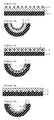
- Figure 1 discloses one embodiment of the invention.
- Figure 1a-b shows a cross-section of the microactuator.
- the microactuator comprises a volume changing material arranged in layer 1.
- This volume changing material could be a conducting polymer, e. g. polypyrrole, polyaniline, or polythiophene.
- the volume changing layer 1 is laminated to a carrier substrate layer 2.
- the carrier substrate layer 2 can be made of a metal or a polymer.
- Arranged on one side of the volume changing layer 1 is a reinforcing structure 3.
- the reinforcing structure can be made of for instance a polymer such as epoxy or polyurethane, or a metal such as gold.
- the examples of materials given for the different components of the microactuator apply to all embodiments.
- the reinforcing structure according to this embodiment is in the form of beam shaped elements arranged transversally in relation to the direction of movement of the microactuator.
- Figure 1a shows the microactuator in a condition when a voltage is applied.
- a normal voltage applied is usually around -1 V for polypyrrole.
- the volume changing layer 1 contracts and the microactuator bends. Due to the reinforcing structure 3 the bending will be controlled and in a predetermined direction.
- FIGS 2-6 also show the microactuator in a condition when the voltage is applied (in Figures a) and when the voltage is not applied (in Figures b) as described above for figure 1 for electrically activated materials.
- the further figures will therefore only be described regarding their construction.
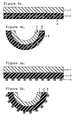
- FIGS 2a-b show a microactuator according to a second embodiment of the invention.
- the microactuator comprises a volume changing layer 1, a carrier substrate layer 2 and a reinforcing structure 3.
- the reinforcing structure 3 is confined within the volume changing layer 1 and not in contact with the carrier substrate 2.
- the reinforcing structure 3 here is in the form of beam shaped elements.
- FIGS 3a-b show a third embodiment of the invention.
- the microactuator according to this embodiment comprises a volume changing layer 1, a carrier substrate layer 2 and a reinforcing structure 3.
- the reinforcing structure 3 is arranged between the volume changing layer 1 and the carrier substrate layer 2.
- the reinforcing structure 3 here is in the form of beam shaped elements.
- FIGS 4a-b show a fourth embodiment of the invention.
- the microactuator according to this embodiment comprises a volume changing layer 1, a carrier substrate layer 2 and a reinforcing structure 3.
- the reinforcing structure' 3 is confined within the carrier substrate layer 2 and not in contact with the volume changing layer 1.
- the reinforcing structure 3 is in the form of beam shaped elements.
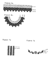
- FIGS 5a-b show a fifth embodiment of the invention.
- the microactuator according to this embodiment comprises a volume changing layer 1, a carrier substrate 2 and a reinforcing structure 3.
- the reinforcing structure 3 arranged outside the carrier substrate layer 2 and not in contact with the volume changing layer 1.
- the reinforcing structure 3 is in the form of beam shaped elements.
- FIGS 6a-b show a microactuator according to a sixth embodiment of the invention.
- the microactuator comprises a volume changing layer 1 and a carrier substrate layer 2.
- a reinforcing structure 3 is arranged by constructing the carrier substrate 2 so that it has varying thickness in different parts of the substrate. The reinforcing structure 3 is thus not made of a separate piece of material in this embodiment.
- Figures 7-9 schematically show groups of microactuators from a top view.
- the microactuators are shown from the top side in an expanded state when a voltage is applied.
- the black areas mark the volume changing layer 1, the top side of the bending areas, that is the areas over which the microactuators will bend.
- the white areas show the arrangement of the reinforcing structure 3.
- the microactuators are formed as elongated rectangles, with a volume changing material 1 and reinforcement structure 3 on top of the carrier substrate 2 (not shown in figures a), constructed as shown in figure 1a-b.
- Figures b show the microactuators when the voltage is removed and the microactuators are in a contracted state.
- the grey areas show the bottom side of the carrier substrate layer 2, that is the side of the microactuator where it bends away from.
- the arrangement of the reinforcing structure determines the movement.
- the volume changing material 1 will bend around the longitudinal axis of the respective elements making up the reinforcing structure 3.
- Figure 7a-b shows three microactuators arranged in parallel according to an embodiment of the invention.
- the configuration of the reinforcing structure 3 shown in figure 7a will lead to the bending pattern in figure 7b.
- the longitudinal axis of reinforcing elements have been arranged perpendicular in relation to the longitudinal axis of the microactuator.
- the resulting structure of the microactuator in the contracted state, as shown in figure 7b will be a roll.
- the reinforcing structure on the outer microactuators are arranged with the longitudinal axis of the reinforcing elements in an angle of about 45 degrees in relation to the longitudinal axis of the microactuators. This results in the spiral configurations shown in figure 7b.
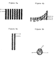
- the group of microactuators consists of eight microactuators arranged in parallel.
- the reinforcing structure 3 is distributed so that the angle between the longitudinal axis of the reinforcing elements and the longitudinal axis of the microactuators changes from one actuator to the next.
- the angle is decreasing from left to right in figure 8a. In the left figure the angle is 90 degrees (perpendicular) and in the far right it is about 20 degrees in relation to the longitudinal axis of the microactuator. This results in a configuration in the contracted state as shown in figure 8b.
- Figure 9a-b illustrates that by combining elements with different arrangements of the reinforcing structure 3 on the microactuator, complex movements can be made.
- Figure 9a-b shows a group of microctuators consisting of two microactuators arranged in parallel.
- the reinforcing elements are arranged in different angles in relation to the longitudinal axis of the microactuator.
- the resulting contracted configuration is shown.
- the microactuators in figure 9b exhibit in their contracted state a knot shape.
- figure 1 and figure 2 be combined with each other, creating an embodiment with a reinforcing structure arranged on the outside of the volume changing layer and a reinforcing structure arranged inside the volume changing layer.
- all the other embodiments shown can be combined with each other to create a stronger reinforcing structure if so needed.
- Any of the embodiments shown in the figures can also be combined with a reinforcing structure arranged in the form of an oriented film. In accordance with the invention more than two ways of constructing the reinforcing structure as described above can be combined together.
- the volume changing layer be of polypyrrole, while the carrier substrate layer is of metal and the reinforcing structure is of polyurethane.
- the volume changing layer may be of polythiophene while the carrier substrate layer is of a polymer and the reinforcing structure is of a metal.
- the reinforcing structure may also be included in the carrier substrate layer and not made up of a separate material.
Landscapes
- Chemical & Material Sciences (AREA)
- Analytical Chemistry (AREA)
- Engineering & Computer Science (AREA)
- Computer Hardware Design (AREA)
- Microelectronics & Electronic Packaging (AREA)
- Micromachines (AREA)
- Laminated Bodies (AREA)
Abstract
Description
- The invention relates to a microactuator comprising a volume changing layer and a carrier substrate layer.
- Microactuators are devices that can exert a force or execute a movement upon external stimulation. Some are made of a bi-layer of a conducting polymer and a carrier substrate of e.g. metal or a polymer. These devices can have lateral dimensions ranging from micrometres to centimetres and layer thickness in the range of nanometres to millimetres.
- When such a microactuator is subjected to an electrical current this causes a relative volume change between the layers. This relative volume change between the layers will lead to a bending movement of the microactuator. Forces stemming from the material with the largest volume change being connected to a material with a smaller volume change cause the bending movement.
- The function of such microactuators is disclosed for instance in E. Smela, O. Inganäs, I. Lundström "Controlled Folding of Micrometer-Size Structures", Science, Vol. 268, p. 1735-1738.
- The development of microactuators has opened up a wide variety of possible new applications, e.g. in electronics and in minimal invasive surgery.
- The bending movement achieved with the above-described construction has been shown to be difficult to control. Therefore, there is a need for a construction, which gives better control of movement.
- It is therefore an object of the invention to solve the above-described problem with control of movement.
- This problem is solved in accordance with the invention by constructing the microactuator so that it comprises a reinforcing structure having an unevenly distributed bending stiffness and so that the reinforcing structure is spread over any of the layers. The spreading of the reinforcing structure over any of the layers includes placing the structure inside any of the layers as well as arranging it on top of any of the layers.
- Microactuators in the sense of the invention are laminated constructions with two significantly larger dimensions, X and Y where the X-dimension is the width and the Y-dimension is the length of the microactuator, and a significantly smaller dimension Z, the thickness of the microactuator. The reinforcing structure is spread in the X-Y-dimensions.
- The term microactuator includes constructions having dimensions in the centimetre scale and downwards. For instance may a microactuator according to the invention have X- and/or Y-dimensions in the centimetre to micrometre scale and a Z-dimension or thickness in the millimetre to nanometre scale.
- A layer with smaller relative volume change will hereinafter be referred to as a carrier substrate layer, and material with a larger relative volume change will be referred to as a volume changing layer.
- A volume changing layer in accordance with the invention refers to a material, which produces a relative difference in volume change compared to the carrier substrate material. Without the relative volume change, the microactuator would not work in the desired manner. Examples of materials that can act as a carrier substrate layer and as volume changing layer will be described.
- In the examples given below, the volume change is electrochemically driven; the stimulus is an applied potential. However, in accordance with the invention, the volume change can also be caused by other chemical or physical principles than electrochemical, such as thermal expansion or solvent induced swelling, using other stimuli than potential.
- The volume changing layer may comprise a conducting polymer, e. g. including pyrrole, aniline, thiophene, para-phenylene, vinylene, and phenylene polymers and copolymers, including substituted forms of the different monomers.
- According to the invention, the reinforcing structure can be arranged in different ways in the microactuator. Preferably the reinforcing structure is arranged as elongated elements that have their longest dimension arranged in the crosswise, or transverse, direction of movement of the microactuator. For instance, the elongated elements can be beam-shaped or rod shaped. That is, the cross-section of the elongated element is square or circular. The reinforcing structure can also be in the form of an oriented film. An oriented film has a bending stiffness that is different in different lateral directions of the film. It is thus the orientated nature of the film that constitutes the reinforcing structures.
- According to some embodiments of the invention, the reinforcing structure can be arranged partly or completely within any of the mentioned layers or outside these layers. The reinforcing structure can also be completely enclosed by, or confined within, any of the mentioned layers. That is, so that the reinforcing structure is only in contact with the layer that it is arranged within. The reinforcing structure can also be arranged between two of the layers that are laminated together, thus enclosing the reinforcing layer. In the case that the reinforcing structure is made of a separate material from that of the volume changing layer and the carrier substrate layer, the reinforcing structure may comprise a cross-linked polymer material, e.g. an epoxy or a polurethane polymer or a copolymer or a substituted polymer thereof. The reinforcing structure may also comprise a metal, such as gold, platinum, titanium, stainless steel or an alloy such as a alloy of nickel and titanium: nitinol. (In T. Duerig, A. Pelton, D. Stöckel, "An overview of nitinol medical applications",Materials Science and Engineering A 273-275 (1999) 149-160, the mechanical properties of nitinol is described).
- According to further embodiments of the invention, the reinforcing structure can be made from the same material as the carrier substrate layer. The reinforcing effect can in this embodiment of the invention be achieved by having different thickness of the material in different parts of the substrate. Another way of achieving the object according to the invention is to corrugate the carrier substrate layer differently in different parts or in other ways change the bending stiffness properties so that it varies over that layer.
- In the embodiment where the reinforcing structure is made from a separate material, it is made from a piece of material separate from both the volume changing layer and the carrier substrate layer.
- In the embodiment where the reinforcing structure is made from a separate material and arranged as a layer, the varied bending stiffness can be achieved in the same manner as described above relating to the carrier substrate, i.e. the reinforcing structure is created by supplying a layer with varying thickness or in other ways arranging the layer so that the bending stiffness differs over the layer.
- It is also possible within the realm of the invention to combine the different embodiments so that it comprises a second reinforcing structure. For instance, a first reinforcing structure arranged as a separate layer and a second reinforcing structure that is arranged in the volume changing layer or the carrier substrate layer. According to the invention the microactuator can also comprise several reinforcing structures.
-
- Figure 1a-b schematically shows the cross-section of a microactuator according to one embodiment of the invention.
- Figure 2a-b schematically shows the cross-section of a microactuator according to a second embodiment of the invention.
- Figure 3a-b schematically shows the cross-section of a microactuator according to a third embodiment of the invention.
- Figure 4a-b schematically shows the cross-section of a microactuator according to a fourth embodiment of the invention.
- Figure 5a-b schematically shows the cross-section of a microactuator according to a fifth embodiment of the invention.
- Figure 6a-b schematically shows the cross-section of a microactuator according to a sixth embodiment of the invention.
- Figure 7a-b shows a microactuator according to an embodiment of the invention seen from the top in an expanded state and in a contracted state.
- Figure 8a-b shows a microactuator according to an embodiment of the invention seen from the top in an expanded state and in a contracted state.
- Figure 9a-b shows a microactuator according to an embodiment of the invention seen from the top in an expanded state and in a contracted state.
- In the following description, an electrically stimulated microactuator is described. The invention is however not limited to electrically stimulated microactuators.
- Although not mentioned in these examples, the microactuator could be made of more than two layers.
- Figure 1 discloses one embodiment of the invention. Figure 1a-b shows a cross-section of the microactuator. The microactuator comprises a volume changing material arranged in
layer 1. This volume changing material could be a conducting polymer, e. g. polypyrrole, polyaniline, or polythiophene. Thevolume changing layer 1 is laminated to acarrier substrate layer 2. Thecarrier substrate layer 2 can be made of a metal or a polymer. Arranged on one side of thevolume changing layer 1 is a reinforcingstructure 3. The reinforcing structure can be made of for instance a polymer such as epoxy or polyurethane, or a metal such as gold. The examples of materials given for the different components of the microactuator apply to all embodiments. The reinforcing structure according to this embodiment is in the form of beam shaped elements arranged transversally in relation to the direction of movement of the microactuator. - Figure 1a shows the microactuator in a condition when a voltage is applied. A normal voltage applied is usually around -1 V for polypyrrole.
When the voltage is removed, thevolume changing layer 1 contracts and the microactuator bends. Due to the reinforcingstructure 3 the bending will be controlled and in a predetermined direction. - Further embodiments shown in Figures 2-6 also show the microactuator in a condition when the voltage is applied (in Figures a) and when the voltage is not applied (in Figures b) as described above for figure 1 for electrically activated materials. The further figures will therefore only be described regarding their construction.
- Figures 2a-b show a microactuator according to a second embodiment of the invention. The microactuator comprises a
volume changing layer 1, acarrier substrate layer 2 and a reinforcingstructure 3. The reinforcingstructure 3 is confined within thevolume changing layer 1 and not in contact with thecarrier substrate 2. The reinforcingstructure 3 here is in the form of beam shaped elements. - Figures 3a-b show a third embodiment of the invention. The microactuator according to this embodiment comprises a
volume changing layer 1, acarrier substrate layer 2 and a reinforcingstructure 3. The reinforcingstructure 3 is arranged between thevolume changing layer 1 and thecarrier substrate layer 2. The reinforcingstructure 3 here is in the form of beam shaped elements. - Figures 4a-b show a fourth embodiment of the invention. The microactuator according to this embodiment comprises a
volume changing layer 1, acarrier substrate layer 2 and a reinforcingstructure 3. The reinforcing structure' 3 is confined within thecarrier substrate layer 2 and not in contact with thevolume changing layer 1. The reinforcingstructure 3 is in the form of beam shaped elements. - Figures 5a-b show a fifth embodiment of the invention. The microactuator according to this embodiment comprises a
volume changing layer 1, acarrier substrate 2 and a reinforcingstructure 3. The reinforcingstructure 3 arranged outside thecarrier substrate layer 2 and not in contact with thevolume changing layer 1. The reinforcingstructure 3 is in the form of beam shaped elements. - Figures 6a-b show a microactuator according to a sixth embodiment of the invention. The microactuator comprises a
volume changing layer 1 and acarrier substrate layer 2. A reinforcingstructure 3 is arranged by constructing thecarrier substrate 2 so that it has varying thickness in different parts of the substrate. The reinforcingstructure 3 is thus not made of a separate piece of material in this embodiment. - Figures 7-9 schematically show groups of microactuators from a top view. In figures a, the microactuators are shown from the top side in an expanded state when a voltage is applied. The black areas mark the
volume changing layer 1, the top side of the bending areas, that is the areas over which the microactuators will bend. The white areas show the arrangement of the reinforcingstructure 3. As an example the microactuators are formed as elongated rectangles, with avolume changing material 1 andreinforcement structure 3 on top of the carrier substrate 2 (not shown in figures a), constructed as shown in figure 1a-b. Figures b show the microactuators when the voltage is removed and the microactuators are in a contracted state. The grey areas show the bottom side of thecarrier substrate layer 2, that is the side of the microactuator where it bends away from. The arrangement of the reinforcing structure determines the movement. Thevolume changing material 1 will bend around the longitudinal axis of the respective elements making up the reinforcingstructure 3. - Figure 7a-b shows three microactuators arranged in parallel according to an embodiment of the invention. The configuration of the reinforcing
structure 3 shown in figure 7a will lead to the bending pattern in figure 7b. In figure 7a can be seen that, in the centre microactuator, the longitudinal axis of reinforcing elements have been arranged perpendicular in relation to the longitudinal axis of the microactuator. With such an arrangement, the resulting structure of the microactuator in the contracted state, as shown in figure 7b, will be a roll. In figure 7a the reinforcing structure on the outer microactuators are arranged with the longitudinal axis of the reinforcing elements in an angle of about 45 degrees in relation to the longitudinal axis of the microactuators. This results in the spiral configurations shown in figure 7b. - In figure 8a-b the group of microactuators consists of eight microactuators arranged in parallel. The reinforcing
structure 3 is distributed so that the angle between the longitudinal axis of the reinforcing elements and the longitudinal axis of the microactuators changes from one actuator to the next. The angle is decreasing from left to right in figure 8a. In the left figure the angle is 90 degrees (perpendicular) and in the far right it is about 20 degrees in relation to the longitudinal axis of the microactuator. This results in a configuration in the contracted state as shown in figure 8b. - Figure 9a-b illustrates that by combining elements with different arrangements of the reinforcing
structure 3 on the microactuator, complex movements can be made. Figure 9a-b shows a group of microctuators consisting of two microactuators arranged in parallel. Here, the reinforcing elements are arranged in different angles in relation to the longitudinal axis of the microactuator. In figure 9b the resulting contracted configuration is shown. The microactuators in figure 9b exhibit in their contracted state a knot shape. - The examples given above are merely given to indicate ways of carrying out the invention and they do not limit the invention. The shown embodiments can be combined in different ways according to the invention.
- For instance can the embodiments of figure 1 and figure 2 be combined with each other, creating an embodiment with a reinforcing structure arranged on the outside of the volume changing layer and a reinforcing structure arranged inside the volume changing layer. In the same manner all the other embodiments shown can be combined with each other to create a stronger reinforcing structure if so needed. Any of the embodiments shown in the figures can also be combined with a reinforcing structure arranged in the form of an oriented film. In accordance with the invention more than two ways of constructing the reinforcing structure as described above can be combined together.
- All the examples given of materials suitable for the respective layers and structures are possible to combine with each other. For instance can the volume changing layer be of polypyrrole, while the carrier substrate layer is of metal and the reinforcing structure is of polyurethane. Or the volume changing layer may be of polythiophene while the carrier substrate layer is of a polymer and the reinforcing structure is of a metal. And so on. The reinforcing structure may also be included in the carrier substrate layer and not made up of a separate material.
Claims (15)
- Microactuator comprising a volume changing layer (1) and a carrier substrate layer (2) carrying the volume changing layer (1),
characterised in that
the microactuator comprises a reinforcing structure (3) having an unevenly distributed bending stiffness, that the reinforcing structure (3) is spread over any of the layers (1), (2) to control a direction of movement of the microactuator. - Microactuator according to claim 1,
characterised in that
the reinforcing structure (3) is made of a separate material. - Microactuator according to claim 2,
characterised in that
the reinforcing structure (3) arranged on either side of the volume changing layer (1), or the carrier substrate layer (2). - Microactuator according to claim 2,
characterised in that
the reinforcing structure (3) is arranged in the volume changing layer (1) or in the carrier substrate layer (2). - Microactuator according to claim 1,
characterised in that
the reinforcing structure (3) is a part of the carrier substrate layer(2). - Microactuator according to any of the preceding claims,
characterised in that
the reinforcing structure (3) is arranged in the form of elongated elements. - Microactuator according to claim 6 having a direction of movement,
characterised in that
the elongated elements (3) are arranged transversely in relation to the direction of movement of the microactuator. - Microactuator according to claim 5,
characterised in that
the reinforcing structure (3) is arranged in the form of added thickness to parts of the carrier substrate layer(2) on either or both sides of said layer. - Microactuator according to claim 2,
characterised in that
the reinforcing structure (3) is arranged as a layer with varying thickness. - Microactuator according to claim 1,
characterised in that
the reinforcing structure (3) comprises an oriented film. - Microactuator according to any one of the preceding claims, characterised in that the reinforcing structure comprises a polymer, including an epoxy or a polurethane polymer, or a copolymer or a substituted polymer thereof, or a metal, including gold, platinum, titanium, stainless steel,- and a nickel-titanium alloy.
- Microactuator according to any one of the preceding claims, characterised in that the volume changing layer (1) comprises a conducting polymer.
- Microactuator according to claim 12, characterised in that the volume changing layer (1) comprises any of the conducting polymers: pyrrole, aniline, thiophene, para-phenylene, vinylene, and phenylene polymers and copolymers thereof, including substituted forms of the different monomers.
- Microactuator according to any one of the preceding claims, characterised in that the carrier substrate layer (2) comprises of a polymer, including an epoxy or a polurethane polymer, or a copolymer or substituted polymer thereof, or a metal, including gold, platinum, titanium, stainless steel, and a nickel-titanium alloy.
- Microactuator according to any one of the preceding claims characterised in that the microactuator has a lateral dimension in the centimetre to micrometre scale and a thickness in the millimetre to nanometre scale.
Applications Claiming Priority (3)
| Application Number | Priority Date | Filing Date | Title |
|---|---|---|---|
| SE0103654 | 2001-11-07 | ||
| SE0103654A SE525649C2 (en) | 2001-11-07 | 2001-11-07 | Microactuator comprising a carrier substrate, a volume-changing layer and a reinforcing structure |
| PCT/EP2002/012481 WO2003039859A1 (en) | 2001-11-07 | 2002-11-06 | Fibre-reinforced microactuator |
Publications (2)
| Publication Number | Publication Date |
|---|---|
| EP1448379A1 EP1448379A1 (en) | 2004-08-25 |
| EP1448379B1 true EP1448379B1 (en) | 2006-01-25 |
Family
ID=20285856
Family Applications (1)
| Application Number | Title | Priority Date | Filing Date |
|---|---|---|---|
| EP02792746A Expired - Lifetime EP1448379B1 (en) | 2001-11-07 | 2002-11-06 | Fibre-reinforced microactuator |
Country Status (7)
| Country | Link |
|---|---|
| US (1) | US6933659B2 (en) |
| EP (1) | EP1448379B1 (en) |
| JP (1) | JP2005517536A (en) |
| AT (1) | ATE316465T1 (en) |
| DE (1) | DE60208930T2 (en) |
| SE (1) | SE525649C2 (en) |
| WO (1) | WO2003039859A1 (en) |
Families Citing this family (12)
| Publication number | Priority date | Publication date | Assignee | Title |
|---|---|---|---|---|
| CA2630215A1 (en) * | 2005-11-17 | 2007-05-24 | Micromuscle Ab | Medical devices and methods for their fabrication and use |
| US7352111B2 (en) * | 2005-12-01 | 2008-04-01 | Schlumberger Technology Corporation | Electroactive polymer pumping system |
| WO2007124128A2 (en) * | 2006-04-20 | 2007-11-01 | Liquidia Technologies, Inc. | Biological vessel flow control devices and methods |
| US8431080B2 (en) * | 2006-06-02 | 2013-04-30 | The Board Of Trustees Of The University Of Illinois | Soft MEMS |
| US9242073B2 (en) * | 2006-08-18 | 2016-01-26 | Boston Scientific Scimed, Inc. | Electrically actuated annelid |
| JP4353975B2 (en) * | 2006-11-29 | 2009-10-28 | 日東電工株式会社 | Adhesive sheet sticking / peeling method, adhesive sheet sticking device, and adhesive sheet peeling device |
| WO2008121033A1 (en) * | 2007-04-03 | 2008-10-09 | Micromuscle Ab | Use of a material in a device, a device, and applications and a method for fabrication thereof |
| DE102007059858A1 (en) * | 2007-12-12 | 2009-06-18 | Bayer Materialscience Ag | Energy converters produced from film-forming aqueous polymer dispersions, in particular polyurethane dispersions |
| US20090177261A1 (en) * | 2008-01-04 | 2009-07-09 | Boston Scientific Scimed, Inc. | Detachment mechanisms for implantable devices |
| JP2012005340A (en) * | 2010-05-18 | 2012-01-05 | Canon Inc | Ion migration-type actuator |
| CN106887517A (en) * | 2017-03-24 | 2017-06-23 | 海鹰企业集团有限责任公司 | A kind of preparation method of curved surface piezoelectric composite |
| DE102022204443B4 (en) | 2022-05-05 | 2026-03-26 | Fraunhofer-Gesellschaft zur Förderung der angewandten Forschung eingetragener Verein | Mechanical systems with adapted linearity |
Family Cites Families (8)
| Publication number | Priority date | Publication date | Assignee | Title |
|---|---|---|---|---|
| DE3429884C2 (en) * | 1983-08-16 | 1987-04-16 | Kureha Kagaku Kogyo K.K., Tokio/Tokyo | A piezoelectric polymer film made of a vinylidene fluoride copolymer in the polarized state and use thereof as an electro-mechanical coupling element for ultrasonic measuring transducers |
| DE4025435C2 (en) * | 1990-08-10 | 2003-07-03 | Siemens Ag | Piezoelectric bending transducer and method for its production |
| DE19620826C2 (en) * | 1996-05-23 | 1998-07-09 | Siemens Ag | Piezoelectric bending transducer and method for its production |
| US6622367B1 (en) * | 1998-02-03 | 2003-09-23 | Salient Interventional Systems, Inc. | Intravascular device and method of manufacture and use |
| DE19920576C1 (en) * | 1999-05-04 | 2000-06-21 | Siemens Ag | Piezoelectric transducer used e.g. as printing head of ink jet printers has a carrier made of a duroplast reinforced with fibers having a specified heat expansion coefficient |
| SE519023C2 (en) * | 1999-06-21 | 2002-12-23 | Micromuscle Ab | Catheter-borne microsurgical tool kit |
| DE10013821B4 (en) * | 2000-03-17 | 2004-01-29 | Technische Universität Dresden | Multi-functional Hybrid Hybrid (FMH) as a force and path translator |
| US6803700B2 (en) * | 2002-06-06 | 2004-10-12 | Caterpillar Inc. | Piezoelectric device |
-
2001
- 2001-11-07 SE SE0103654A patent/SE525649C2/en not_active IP Right Cessation
-
2002
- 2002-11-06 DE DE60208930T patent/DE60208930T2/en not_active Expired - Lifetime
- 2002-11-06 AT AT02792746T patent/ATE316465T1/en not_active IP Right Cessation
- 2002-11-06 EP EP02792746A patent/EP1448379B1/en not_active Expired - Lifetime
- 2002-11-06 WO PCT/EP2002/012481 patent/WO2003039859A1/en not_active Ceased
- 2002-11-06 US US10/494,587 patent/US6933659B2/en not_active Expired - Fee Related
- 2002-11-06 JP JP2003541728A patent/JP2005517536A/en active Pending
Also Published As
| Publication number | Publication date |
|---|---|
| DE60208930T2 (en) | 2006-10-26 |
| SE0103654L (en) | 2003-05-08 |
| DE60208930D1 (en) | 2006-04-13 |
| JP2005517536A (en) | 2005-06-16 |
| WO2003039859A1 (en) | 2003-05-15 |
| US6933659B2 (en) | 2005-08-23 |
| SE0103654D0 (en) | 2001-11-07 |
| EP1448379A1 (en) | 2004-08-25 |
| US20040251794A1 (en) | 2004-12-16 |
| SE525649C2 (en) | 2005-03-29 |
| ATE316465T1 (en) | 2006-02-15 |
Similar Documents
| Publication | Publication Date | Title |
|---|---|---|
| US6933659B2 (en) | Fiber-reinforced microactuator | |
| Kim et al. | Low-voltage-driven soft actuators | |
| Bar-Cohen | Electroactive polymers as artificial muscles-reality and challenges | |
| Baughman | Conducting polymer artificial muscles | |
| Shahinpoor et al. | Ionic polymer-metal composites (IPMCs) as biomimetic sensors, actuators and artificial muscles-a review | |
| JP3811495B2 (en) | Actuator and method of manufacturing flat electrode support for actuator | |
| EP1737564B1 (en) | Mechanical meta-materials | |
| Meng et al. | A brief review of stimulus-active polymers responsive to thermal, light, magnetic, electric, and water/solvent stimuli | |
| Smela | Conjugated polymer actuators | |
| US20070257582A1 (en) | Polymer actuator | |
| JP2012523809A (en) | Electrically switchable polymer membrane assembly and use thereof | |
| EP4337443B1 (en) | Auxetic web structure or field structure, and use | |
| Liu et al. | Electrochemical actuator based on polypyrrole/sulfonated graphene/graphene tri-layer film | |
| US20070138341A1 (en) | Transformable skin | |
| Samatham et al. | Active polymers: an overview | |
| Fu et al. | Recent progress of morphable 3D mesostructures in advanced materials | |
| Shahinpoor | Artificial muscles | |
| EP2002535B1 (en) | Electromechanical transducer | |
| JP2009189220A (en) | Actuator and actuator structure using the same | |
| CN116104891A (en) | A metal rubber-based negative Poisson's ratio metamaterial structure and working method | |
| US20260132773A1 (en) | Film actuator and method for manufacturing the same | |
| Luo et al. | Mechanics‐Guided 3 D Assembly of Flexible Electronics | |
| Ward et al. | Polypyrrole derivatives in the design of electrochemically driven actuators | |
| Otero et al. | Attempting a classification for electrical polymeric actuators | |
| Bar-Cohen | NDEAA Technologies, JPL/Caltech, Pasadena, CA yosi@ jpl. nasa. gov, http://ndeaa. jpl. nasa. gov |
Legal Events
| Date | Code | Title | Description |
|---|---|---|---|
| PUAI | Public reference made under article 153(3) epc to a published international application that has entered the european phase |
Free format text: ORIGINAL CODE: 0009012 |
|
| 17P | Request for examination filed |
Effective date: 20040518 |
|
| AK | Designated contracting states |
Kind code of ref document: A1 Designated state(s): AT BE BG CH CY CZ DE DK EE ES FI FR GB GR IE IT LI LU MC NL PT SE SK TR |
|
| AX | Request for extension of the european patent |
Extension state: AL LT LV MK RO SI |
|
| GRAP | Despatch of communication of intention to grant a patent |
Free format text: ORIGINAL CODE: EPIDOSNIGR1 |
|
| GRAS | Grant fee paid |
Free format text: ORIGINAL CODE: EPIDOSNIGR3 |
|
| GRAA | (expected) grant |
Free format text: ORIGINAL CODE: 0009210 |
|
| AK | Designated contracting states |
Kind code of ref document: B1 Designated state(s): AT BE BG CH CY CZ DE DK EE ES FI FR GB GR IE IT LI LU MC NL PT SE SK TR |
|
| PG25 | Lapsed in a contracting state [announced via postgrant information from national office to epo] |
Ref country code: IT Free format text: LAPSE BECAUSE OF FAILURE TO SUBMIT A TRANSLATION OF THE DESCRIPTION OR TO PAY THE FEE WITHIN THE PRESCRIBED TIME-LIMIT;WARNING: LAPSES OF ITALIAN PATENTS WITH EFFECTIVE DATE BEFORE 2007 MAY HAVE OCCURRED AT ANY TIME BEFORE 2007. THE CORRECT EFFECTIVE DATE MAY BE DIFFERENT FROM THE ONE RECORDED. Effective date: 20060125 Ref country code: NL Free format text: LAPSE BECAUSE OF FAILURE TO SUBMIT A TRANSLATION OF THE DESCRIPTION OR TO PAY THE FEE WITHIN THE PRESCRIBED TIME-LIMIT Effective date: 20060125 Ref country code: BE Free format text: LAPSE BECAUSE OF FAILURE TO SUBMIT A TRANSLATION OF THE DESCRIPTION OR TO PAY THE FEE WITHIN THE PRESCRIBED TIME-LIMIT Effective date: 20060125 Ref country code: AT Free format text: LAPSE BECAUSE OF FAILURE TO SUBMIT A TRANSLATION OF THE DESCRIPTION OR TO PAY THE FEE WITHIN THE PRESCRIBED TIME-LIMIT Effective date: 20060125 Ref country code: SK Free format text: LAPSE BECAUSE OF FAILURE TO SUBMIT A TRANSLATION OF THE DESCRIPTION OR TO PAY THE FEE WITHIN THE PRESCRIBED TIME-LIMIT Effective date: 20060125 Ref country code: CH Free format text: LAPSE BECAUSE OF FAILURE TO SUBMIT A TRANSLATION OF THE DESCRIPTION OR TO PAY THE FEE WITHIN THE PRESCRIBED TIME-LIMIT Effective date: 20060125 Ref country code: LI Free format text: LAPSE BECAUSE OF FAILURE TO SUBMIT A TRANSLATION OF THE DESCRIPTION OR TO PAY THE FEE WITHIN THE PRESCRIBED TIME-LIMIT Effective date: 20060125 Ref country code: FI Free format text: LAPSE BECAUSE OF FAILURE TO SUBMIT A TRANSLATION OF THE DESCRIPTION OR TO PAY THE FEE WITHIN THE PRESCRIBED TIME-LIMIT Effective date: 20060125 |
|
| REG | Reference to a national code |
Ref country code: GB Ref legal event code: FG4D |
|
| REG | Reference to a national code |
Ref country code: CH Ref legal event code: EP |
|
| REG | Reference to a national code |
Ref country code: IE Ref legal event code: FG4D |
|
| REF | Corresponds to: |
Ref document number: 60208930 Country of ref document: DE Date of ref document: 20060413 Kind code of ref document: P |
|
| PG25 | Lapsed in a contracting state [announced via postgrant information from national office to epo] |
Ref country code: BG Free format text: LAPSE BECAUSE OF FAILURE TO SUBMIT A TRANSLATION OF THE DESCRIPTION OR TO PAY THE FEE WITHIN THE PRESCRIBED TIME-LIMIT Effective date: 20060425 Ref country code: SE Free format text: LAPSE BECAUSE OF FAILURE TO SUBMIT A TRANSLATION OF THE DESCRIPTION OR TO PAY THE FEE WITHIN THE PRESCRIBED TIME-LIMIT Effective date: 20060425 Ref country code: DK Free format text: LAPSE BECAUSE OF FAILURE TO SUBMIT A TRANSLATION OF THE DESCRIPTION OR TO PAY THE FEE WITHIN THE PRESCRIBED TIME-LIMIT Effective date: 20060425 |
|
| PG25 | Lapsed in a contracting state [announced via postgrant information from national office to epo] |
Ref country code: ES Free format text: LAPSE BECAUSE OF FAILURE TO SUBMIT A TRANSLATION OF THE DESCRIPTION OR TO PAY THE FEE WITHIN THE PRESCRIBED TIME-LIMIT Effective date: 20060506 |
|
| PG25 | Lapsed in a contracting state [announced via postgrant information from national office to epo] |
Ref country code: PT Free format text: LAPSE BECAUSE OF FAILURE TO SUBMIT A TRANSLATION OF THE DESCRIPTION OR TO PAY THE FEE WITHIN THE PRESCRIBED TIME-LIMIT Effective date: 20060626 |
|
| NLV1 | Nl: lapsed or annulled due to failure to fulfill the requirements of art. 29p and 29m of the patents act | ||
| REG | Reference to a national code |
Ref country code: CH Ref legal event code: PL |
|
| ET | Fr: translation filed | ||
| PG25 | Lapsed in a contracting state [announced via postgrant information from national office to epo] |
Ref country code: MC Free format text: LAPSE BECAUSE OF NON-PAYMENT OF DUE FEES Effective date: 20061130 |
|
| PLBE | No opposition filed within time limit |
Free format text: ORIGINAL CODE: 0009261 |
|
| STAA | Information on the status of an ep patent application or granted ep patent |
Free format text: STATUS: NO OPPOSITION FILED WITHIN TIME LIMIT |
|
| 26N | No opposition filed |
Effective date: 20061026 |
|
| PG25 | Lapsed in a contracting state [announced via postgrant information from national office to epo] |
Ref country code: GR Free format text: LAPSE BECAUSE OF FAILURE TO SUBMIT A TRANSLATION OF THE DESCRIPTION OR TO PAY THE FEE WITHIN THE PRESCRIBED TIME-LIMIT Effective date: 20060426 Ref country code: CZ Free format text: LAPSE BECAUSE OF FAILURE TO SUBMIT A TRANSLATION OF THE DESCRIPTION OR TO PAY THE FEE WITHIN THE PRESCRIBED TIME-LIMIT Effective date: 20060125 |
|
| PG25 | Lapsed in a contracting state [announced via postgrant information from national office to epo] |
Ref country code: EE Free format text: LAPSE BECAUSE OF FAILURE TO SUBMIT A TRANSLATION OF THE DESCRIPTION OR TO PAY THE FEE WITHIN THE PRESCRIBED TIME-LIMIT Effective date: 20060125 |
|
| PG25 | Lapsed in a contracting state [announced via postgrant information from national office to epo] |
Ref country code: LU Free format text: LAPSE BECAUSE OF NON-PAYMENT OF DUE FEES Effective date: 20061106 Ref country code: TR Free format text: LAPSE BECAUSE OF FAILURE TO SUBMIT A TRANSLATION OF THE DESCRIPTION OR TO PAY THE FEE WITHIN THE PRESCRIBED TIME-LIMIT Effective date: 20060125 |
|
| PG25 | Lapsed in a contracting state [announced via postgrant information from national office to epo] |
Ref country code: CY Free format text: LAPSE BECAUSE OF FAILURE TO SUBMIT A TRANSLATION OF THE DESCRIPTION OR TO PAY THE FEE WITHIN THE PRESCRIBED TIME-LIMIT Effective date: 20060125 |
|
| REG | Reference to a national code |
Ref country code: GB Ref legal event code: 732E Free format text: REGISTERED BETWEEN 20091001 AND 20091007 |
|
| PGFP | Annual fee paid to national office [announced via postgrant information from national office to epo] |
Ref country code: FR Payment date: 20101117 Year of fee payment: 9 Ref country code: IE Payment date: 20101123 Year of fee payment: 9 |
|
| PGFP | Annual fee paid to national office [announced via postgrant information from national office to epo] |
Ref country code: DE Payment date: 20101103 Year of fee payment: 9 |
|
| PGFP | Annual fee paid to national office [announced via postgrant information from national office to epo] |
Ref country code: GB Payment date: 20101103 Year of fee payment: 9 |
|
| GBPC | Gb: european patent ceased through non-payment of renewal fee |
Effective date: 20111106 |
|
| REG | Reference to a national code |
Ref country code: FR Ref legal event code: ST Effective date: 20120731 |
|
| REG | Reference to a national code |
Ref country code: IE Ref legal event code: MM4A |
|
| REG | Reference to a national code |
Ref country code: DE Ref legal event code: R119 Ref document number: 60208930 Country of ref document: DE Effective date: 20120601 |
|
| PG25 | Lapsed in a contracting state [announced via postgrant information from national office to epo] |
Ref country code: GB Free format text: LAPSE BECAUSE OF NON-PAYMENT OF DUE FEES Effective date: 20111106 Ref country code: IE Free format text: LAPSE BECAUSE OF NON-PAYMENT OF DUE FEES Effective date: 20111106 |
|
| PG25 | Lapsed in a contracting state [announced via postgrant information from national office to epo] |
Ref country code: FR Free format text: LAPSE BECAUSE OF NON-PAYMENT OF DUE FEES Effective date: 20111130 |
|
| PG25 | Lapsed in a contracting state [announced via postgrant information from national office to epo] |
Ref country code: DE Free format text: LAPSE BECAUSE OF NON-PAYMENT OF DUE FEES Effective date: 20120601 |