EP1447979A1 - Liquid crystal projector with plural light sources and circuit for correcting the video signal in dependance thereof - Google Patents
Liquid crystal projector with plural light sources and circuit for correcting the video signal in dependance thereof Download PDFInfo
- Publication number
- EP1447979A1 EP1447979A1 EP04002447A EP04002447A EP1447979A1 EP 1447979 A1 EP1447979 A1 EP 1447979A1 EP 04002447 A EP04002447 A EP 04002447A EP 04002447 A EP04002447 A EP 04002447A EP 1447979 A1 EP1447979 A1 EP 1447979A1
- Authority
- EP
- European Patent Office
- Prior art keywords
- lamps
- data
- liquid crystal
- circuit
- energized
- Prior art date
- Legal status (The legal status is an assumption and is not a legal conclusion. Google has not performed a legal analysis and makes no representation as to the accuracy of the status listed.)
- Granted
Links
- 239000004973 liquid crystal related substance Substances 0.000 title claims abstract description 120
- 238000000034 method Methods 0.000 claims abstract description 19
- 238000002834 transmittance Methods 0.000 claims description 8
- 238000004519 manufacturing process Methods 0.000 abstract description 4
- 230000003287 optical effect Effects 0.000 description 13
- 238000004364 calculation method Methods 0.000 description 8
- 238000012937 correction Methods 0.000 description 5
- 238000010586 diagram Methods 0.000 description 5
- 239000003086 colorant Substances 0.000 description 2
- 238000005516 engineering process Methods 0.000 description 2
- 238000006243 chemical reaction Methods 0.000 description 1
- 230000001788 irregular Effects 0.000 description 1
Images


Classifications
-
- H—ELECTRICITY
- H04—ELECTRIC COMMUNICATION TECHNIQUE
- H04N—PICTORIAL COMMUNICATION, e.g. TELEVISION
- H04N9/00—Details of colour television systems
- H04N9/12—Picture reproducers
- H04N9/31—Projection devices for colour picture display, e.g. using electronic spatial light modulators [ESLM]
- H04N9/3179—Video signal processing therefor
- H04N9/3182—Colour adjustment, e.g. white balance, shading or gamut
-
- H—ELECTRICITY
- H04—ELECTRIC COMMUNICATION TECHNIQUE
- H04N—PICTORIAL COMMUNICATION, e.g. TELEVISION
- H04N5/00—Details of television systems
- H04N5/74—Projection arrangements for image reproduction, e.g. using eidophor
- H04N5/7416—Projection arrangements for image reproduction, e.g. using eidophor involving the use of a spatial light modulator, e.g. a light valve, controlled by a video signal
- H04N5/7441—Projection arrangements for image reproduction, e.g. using eidophor involving the use of a spatial light modulator, e.g. a light valve, controlled by a video signal the modulator being an array of liquid crystal cells
Definitions
- the present invention is concerned with an LCD panel driver circuit for use in a transmissive liquid crystal projector having a plurality of lamps as light sources (hereinafter also referred to as "multi-lamp liquid crystal projector").
- the LCD panel driver circuit has characteristic data and corrective data for the respective lamps for correcting different voltage vs. transmittance characteristics produced when the lamps are independently energized, due to different angles at which the optical axes of the lamps extend with respect to the liquid crystal panel, or correcting color irregularities produced when three colors, R, G, B, are combined, due to irregular amounts of light emitted from three liquid crystal panels, e.g., light in three colors, R, G, B.
- a liquid crystal projector having two lamps as light sources has been described.
- the number of lamps that can be used is not limited to two, and data for correcting the VT characteristics of lamps may be prepared depending on the number of the lamps.
Landscapes
- Engineering & Computer Science (AREA)
- Multimedia (AREA)
- Signal Processing (AREA)
- Chemical & Material Sciences (AREA)
- Crystallography & Structural Chemistry (AREA)
- Liquid Crystal (AREA)
- Liquid Crystal Display Device Control (AREA)
- Control Of Indicators Other Than Cathode Ray Tubes (AREA)
- Projection Apparatus (AREA)
Abstract
Description
- The present invention relates to a circuit for driving the liquid crystal panel of a liquid crystal projector, and more particularly to a circuit for and a method of driving the liquid crystal panel of a liquid crystal projector which has a plurality of lamps as light sources.
- Fig. 1 of the accompanying drawings is a block diagram showing an arrangement of an LCD driver circuit of a conventional liquid crystal projector.
- As shown in Fig. 1, the LCD driver circuit of the conventional liquid crystal projector comprises
CPU circuit 404 for managing the overall system and data of the liquid crystal projector, videosignal processing circuit 405 for converting a video signal input from an external source into a digital signal with an A/D converter,panel correcting circuit 406 for correcting the digital video signal generated by videosignal processing circuit 405 depending on the voltage vs. transmittance characteristics of a liquid crystal panel of the liquid crystal projector so as to match the liquid crystal panel, and liquid crystalpanel timing circuit 407 for generating timing pulses for driving the liquid crystal panel. - If the video signal processed by video
signal processing circuit 405 is directly applied to the liquid crystal panel, then, as shown in Fig. 2(a) of the accompanying drawings, a video image displayed on the liquid crystal panel will have poor gradations with uniform black and white levels due to the VT characteristics of the liquid crystal panel. When the video signal is corrected depending on the VT characteristics of the liquid crystal panel by liquid crystalpanel timing circuit 407, a video image with good gradations is displayed on the liquid crystal panel, as shown in Fig. 2(b) of the accompanying drawings. - Heretofore, a lookup table (hereinafter referred to as "LUT") process has been used as a means for performing the VT characteristics correction on video signals. According to the LUT process, an input video signal is corrected to produce an output video signal based on data conversion using an LUT.
- Single-lamp liquid crystal projectors having a single lamp as a light source may have only one pattern of VT characteristic correction data as data inherent in the single-lamp liquid crystal projectors.
- Proposals for using a plurality of lamps as light sources in addition to increasing the light output of a single light source, as a means for providing a higher-luminance liquid crystal projector, are disclosed in Japanese laid-open patent publication No. 2001-166378 (patent document 1) and Japanese laid-open patent publication No. 6-265887 (patent document 2), for example.
- One of the basic conditions for obtaining good video images on the final focusing screen of a liquid crystal projector is to apply light perpendicular and uniformly to the liquid crystal panel. Liquid crystal projectors having a plurality of light sources for achieving higher luminance have some peculiar problems in employing the plural light sources.
- The invention disclosed in Japanese laid-open patent publication No. 6-265887 is addressed to the problem that a single-lamp liquid crystal projector will fail to display any images if the single light source is de-energized for some reasons. This publication reveals an illuminating device comprising a plurality of light sources, a light valve for modulating output light from the illuminating device with image information to produce a light image depending on the image information, and a uniform illuminating optical element disposed between the illuminating device and the light valve.
- The invention disclosed in Japanese laid-open patent publication No. 2001-166378 is addressed to the problem that according to the arrangement disclosed in Japanese laid-open patent publication No. 6-265887, images from the respective light sources are separated into left and right images, and optical path differences are developed between R, G, B light beams, resulting in color irregularities. This publication shows two light sources and an optical system for combining light beams emitted from the respective light sources using a reflecting prism.
- The technologies disclosed in Japanese laid-open patent publication No. 2001-166378 (patent document 1) and Japanese laid-open patent publication No. 6-265887 (patent document 2) serve to produce images of good quality with a projector having two lamps as light sources. Each of these technologies is based on optical system improvements for applying more uniform light to a liquid crystal panel. In a liquid crystal projector having a plurality of lamps, attempts to align the optical axes of the lamps would require complex arrangements and would be tedious and time-consuming, resulting in an increase in the manufacturing cost. These problems aggravate themselves if the number of lamps used as lamps increase.
- The present invention has been made in view of the above problems of the conventional liquid crystal projectors. It is an object of the present invention to provide a circuit for and a method of driving the liquid crystal panel of a liquid crystal projector, which circuit and method make it possible to manufacture a projector having a plurality of light sources inexpensively.
- According to the present invention, there is provided a circuit for driving the liquid crystal panel of a liquid crystal projector having a plurality of lamps as light sources, comprising a CPU circuit for managing overall system and data of the liquid crystal projector, a video signal processing circuit for converting a video signal input from an external source into a digital signal, and a panel correcting circuit for correcting the digital video signal generated by the video signal processing circuit depending on characteristics of a liquid crystal panel of the liquid crystal projector so as to match the liquid crystal panel, wherein the CPU circuit outputs corrective data depending on how the lamps are energized to the panel correcting circuit, and the panel correcting circuit corrects the video signal using the corrective data.
- The liquid crystal panel may be of the transmissive type, and the CPU circuit may output corrective data to the panel correcting circuit depending on the voltage vs. transmittance characteristics, which vary depending on how the lamps are energized, of the liquid crystal panel.
- The liquid crystal panel may be of the reflective type, and the CPU circuit may output corrective data to the panel correcting circuit depending on the voltage vs. reflectance characteristics, which vary depending on how the lamps are energized, of the liquid crystal panel.
- The CPU circuit may have data which are different from each other depending on how the lamps are energized, for correcting the video signal depending on the characteristics of the liquid crystal panel in the panel correcting circuit, and output corresponding data depending on how the lamps are energized as corrective data to the panel correcting circuit.
- The lamps may include two lamps, and the CPU circuit may have two data available when the two respective lamps are independently energized, calculates data corresponding to a state in which the two lamps are simultaneously energized, from the two data, and output corresponding data depending on how the lamps are energized as corrective data to the panel correcting circuit.
- The lamps may include two lamps, and the CPU circuit may have data available when the two lamps are simultaneously energized, calculate data corresponding to a state in which the two lamps are independently energized, from the data available when two lamps are simultaneously energized, and output corresponding data depending on how the lamps are energized as corrective data to the panel correcting circuit.
- The CPU circuit may store equations for obtaining the same results as data which are different from each other depending on how the lamps are energized, for correcting the video signal depending on the characteristics of the liquid crystal panel in the panel correcting circuit, calculate data which are different from each other depending on how the lamps are energized according to the stored equations, and output the calculated data as corrective data to the panel correcting circuit.
- According to the present invention, there is also provided a method of driving the liquid crystal panel of a liquid crystal projector having a plurality of lamps as light sources, with a liquid crystal panel driver circuit comprising control means for managing the overall system and data of the liquid crystal projector, video signal processing means for converting a video signal input from an external source into a digital signal, and panel correcting means for correcting the digital video signal generated by the video signal processing circuit depending on characteristics of a liquid crystal panel of the liquid crystal projector so as to match the liquid crystal panel, the method comprising the steps of outputting corrective data depending on how the lamps are energized from the control means to the panel correcting means, and correcting the video signal with the panel correcting means using the corrective data.
- The liquid crystal panel may be of the transmissive type, and the control means may output corrective data to the panel correcting means depending on the voltage vs. transmittance characteristics, which vary depending on how the lamps are energized, of the liquid crystal panel.
- The liquid crystal panel may be of the reflective type, and the control means may output corrective data to the panel correcting means depending on the voltage vs. reflectance characteristics, which vary depending on how the lamps are energized, of the liquid crystal panel.
- The control means may have data which are different from each other depending on how the lamps are energized, for correcting the video signal depending on the characteristics of the liquid crystal panel in the panel correcting means, and output corresponding data depending on how the lamps are energized as corrective data to the panel correcting means.
- The lamps may include two lamps, and the control means may have two data available when two respective lamps are independently energized, calculate data corresponding to a state in which the two lamps are simultaneously energized, from the two data, and output corresponding data depending on how the lamps are energized as corrective data to the panel correcting means.
- The lamps may include two lamps, and the control means may have data available when two lamps are simultaneously energized, calculate data corresponding to a state in which the two lamps are independently energized, from the data available when two lamps are simultaneously energized, and output corresponding data depending on how the lamps are energized as corrective data to the panel correcting means.
- The control means may store equations for obtaining the same results as data which are different from each other depending on how the lamps are energized, for correcting the video signal depending on the characteristics of the liquid crystal panel in the panel correcting circuit, calculate data which are different from each other depending on how the lamps are energized according to the stored equations, and output the calculated data as corrective data to the panel correcting means.
- The present invention is concerned with an LCD panel driver circuit for use in a transmissive liquid crystal projector having a plurality of lamps as light sources (hereinafter also referred to as "multi-lamp liquid crystal projector"). The LCD panel driver circuit has characteristic data and corrective data for the respective lamps for correcting different voltage vs. transmittance characteristics produced when the lamps are independently energized, due to different angles at which the optical axes of the lamps extend with respect to the liquid crystal panel, or correcting color irregularities produced when three colors, R, G, B, are combined, due to irregular amounts of light emitted from three liquid crystal panels, e.g., light in three colors, R, G, B.
- The LCD panel driver circuit also generates characteristic data and corrective data at the time the lamps are simultaneously generated, from a plurality of corrective data, for optimizing VT characteristics correcting data or color irregularity correcting data at the time the lamps are simultaneously generated.
- According to the present invention, even if light beams emitted from the lamps of the multi-lamp liquid crystal projector are applied at respective different angles to the liquid crystal panel, corrections inherent in the liquid crystal projector, typically optimum VT characteristics corrections and color irregularity corrections, can be made for producing optimum video images.
- The above and other objects, features, and advantages of the present invention will become apparent from the following description with reference to the accompanying drawings which illustrate an example of the present invention.
-
- Fig. 1 is a block diagram of an arrangement of an LCD driver circuit of a conventional liquid crystal projector;
- Figs. 2(a) and 2(b) are diagrams showing gradations of images displayed by a liquid crystal projector;
- Fig. 3 is a view showing an optical system of a liquid crystal projector according to the present invention;
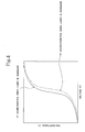
- Fig. 4 is a diagram showing the voltage vs. transmittance characteristics of lamps of the liquid crystal projector based on different angles at which the optical axes of the lamps extend at different angles with respect to a liquid crystal panel; and
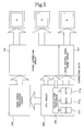
- Fig. 5 is a block diagram of an arrangement of an LCD driver circuit according to an embodiment of the present invention.
-
- Fig. 3 shows an optical system of a liquid crystal projector according to the present invention.
- As shown in Fig. 3, the optical system has two
lamps 1, 2. Illuminating light emitted from each oflamps 1, 2 is applied to transmissiveliquid crystal panel 3.Lamps 1, 2 have respective optical axes different from each other which extend at different angles with respect toliquid crystal panel 3. - Fig. 4 shows the voltage vs. transmittance characteristics (hereinafter referred to as "VT characteristics") of
lamps 1, 2 based on the different angles at which the respective optical axes oflamps 1, 2 extend with respect toliquid crystal panel 3. As shown in Fig. 4, the optical axes ofrespective lamps 1, 2 extend at different angles with respect toliquid crystal panel 3. Because of the angle of field ofliquid crystal panel 3, the VT characteristics which are produced when only lamp 1 is energized are different from the VT characteristics which are produced when onlylamp 2 is energized. Although not shown the VT characteristics which are produced when bothlamps 1, 2 are simultaneously energized are different from the VT characteristics illustrated in Fig. 4. - Fig. 5 shows in block form an arrangement of an LCD driver circuit according to an embodiment of the present invention.
- As shown in Fig. 5, the LCD driver circuit has
CPU circuit 308 as a control means according to the embodiment, videosignal processing circuit 305,panel correcting circuit 306, and liquid crystalpanel timing circuit 307.CPU circuit 308, videosignal processing circuit 305,panel correcting circuit 306, and liquid crystalpanel timing circuit 307 operate in the manner as withCPU circuit 404, videosignal processing circuit 405,panel correcting circuit 406, and liquid crystalpanel timing circuit 407 shown in Fig. 1. However,CPU circuit 308 according to the present embodiment includes data 3101 through 3103 for correcting the VT characteristics, andcalculation processor 309 for generating data for correcting the VT characteristics into optimum VT characteristics based on data 3101 through 3103. - Of data 3101 through 3103, data 3101 are data for correcting the VT characteristics produced when only lamp 1 is energized, data 3102 are data for correcting the VT characteristics produced when only
lamp 2 is energized, and data 3103 are data for correcting the VT characteristics produced when bothlamps 1, 2 are energized. -
CPU circuit 308 reads either one of data 3101 through 3103 depending on howlamps 1, 2 are energized, and transfers the read data tocalculation processor 309. Whencalculation processor 309 receives either one of data 3101 through 3103, if no instruction is given together with the data, thencalculation processor 309 outputs the received data directly as corrective data topanel correcting circuit 306. - If lamps having different luminance levels due to their used times are employed as
lamps 1, 2, then even when the VT characteristics are corrected with data 3101 through 3103, displayed images that are finally synthesized by the liquid crystal projector may not be sufficiently high in quality.Calculation processor 309 is provided to avoid the above drawback. Whencalculation processor 309 receives either one of data 3101 through 3103 together with an input representing the used times oflamps 1, 2 and an instruction for making adjustments depending on the used times oflamps 1, 2,calculation processor 309 corrects the received data depending on one or both of the used times, and outputs the corrected data topanel correcting circuit 306. - There are available various processes of correcting the received data with
calculation processor 309. For example, if lamp 1 andlamp 2 are of the same type, then since the luminance difference therebetween can be estimated from the used times thereof, it is possible to correct the data depending on the used times oflamps 1, 2. - Alternatively, the user who will observe displayed images that are finally synthesized may manually enter an instruction for making adjustments, and it is possible to correct the data depending on the entered instruction.
- Further alternatively, a detector for observing displayed images that are finally synthesized may be provided, and it is possible to correct the data depending on the output of the detector.
- Data 3101 through 3103 are stored as LUT data. Alternatively, equations capable of producing the same results as data 3101 through 3103 may be stored, and a signal processor may be used to output corrective data according to the stored equations. Use of the equations offers the same advantages as with data 3101 through 3103, and in addition can reduce the amount of stored data.
- If the VT characteristics have certain regularity, e.g., if data for correcting the VT characteristics of the lamps can be estimated from data for correcting the VT characteristics at the time the lamps are energized, or conversely if data for correcting the VT characteristics at the time the lamps are energized can be estimated from data for correcting the VT characteristics of the lamps, then one or two sets of data may be stored, and data in other modes may be calculated, thereby reducing the amount of stored data. The stored data may be stored as LUT data or equations capable of producing the same results as those data may be stored.
- In the above embodiment, a liquid crystal projector having two lamps as light sources has been described. The number of lamps that can be used is not limited to two, and data for correcting the VT characteristics of lamps may be prepared depending on the number of the lamps.
- The liquid crystal panel has been described as of the transmissive type. However, the liquid crystal panel may be of the reflective type. The transmissive liquid crystal panel tends to cause color irregularities due to different VT characteristics. Similarly, the reflective liquid crystal panel is liable to cause the same problem because of different voltage vs. reflectance characteristics. Therefore, a liquid crystal projector having a reflective liquid crystal panel may have data for correcting the voltage vs. reflectance characteristics rather than data for correcting the VT characteristics, thus offering the same advantages as those described above in the illustrated embodiment.
- The present invention thus arranged offers the following advantages.
- Since the characteristics are appropriately corrected depending on how the lamps are energized, it is possible to provide a circuit for and a method of driving the liquid crystal panel of a liquid crystal projector, which circuit and method make it possible to manufacture a projector having a plurality of light sources inexpensively.
- While a preferred embodiment of the present invention has been described using specific terms, such description is for illustrative purposes only, and it is to be understood that changes and variations may be made without departing from the spirit or scope of the following claims.
Claims (14)
- A circuit for driving the liquid crystal panel of a liquid crystal projector having a plurality of lamps as light sources, comprising:wherein said CPU circuit outputs corrective data depending on how the lamps are energized to said panel correcting circuit, and said panel correcting circuit corrects the video signal using said corrective data.a CPU circuit for managing the overall system and data of the liquid crystal projector;a video signal processing circuit for converting a video signal input from an external source into a digital signal; anda panel correcting circuit for correcting the digital video signal generated by said video signal processing circuit depending on characteristics of a liquid crystal panel of the liquid crystal projector so as to match the liquid crystal panel;
- A circuit according to claim 1, wherein said liquid crystal panel is of the transmissive type, and said CPU circuit outputs corrective data depending on the voltage vs. transmittance characteristics, which vary depending on how the lamps are energized, of the liquid crystal panel to said panel correcting circuit.
- A circuit according to claim 1, wherein said liquid crystal panel is of the reflective type, and said CPU circuit outputs corrective data depending on the voltage vs. reflectance characteristics, which vary depending on how the lamps are energized, of the liquid crystal panel to said panel correcting circuit.
- A circuit according to any one of claims 1 through 3, wherein said CPU circuit has data which are different from each other depending on how the lamps are energized, for correcting the video signal depending on the characteristics of the liquid crystal panel in the panel correcting circuit, and outputs corresponding data depending on how the lamps are energized as corrective data to said panel correcting circuit.
- A circuit according to any one of claims 1 through 3, wherein said lamps include two lamps, and said CPU circuit has two data available when the two respective lamps are independently energized, calculates data corresponding to a state in which the two lamps are simultaneously energized, from said two data, and outputs corresponding data depending on how the lamps are energized as corrective data to said panel correcting circuit.
- A circuit according to any one of claims 1 through 3, wherein said lamps include two lamps, and said CPU circuit has data available when the two lamps are simultaneously energized, calculates data corresponding to a state in which the two lamps are independently energized, from said data available when two lamps are simultaneously energized, and outputs corresponding data depending on how the lamps are energized as corrective data to said panel correcting circuit.
- A circuit according to any one of claims 1 through 6, wherein said CPU circuit stores equations for obtaining the same results as data which are different from each other depending on how the lamps are energized, for correcting the video signal depending on the characteristics of the liquid crystal panel in the panel correcting circuit, calculates data which are different from each other depending on how the lamps are energized according to the stored equations, and outputs the calculated data as corrective data to said panel correcting circuit.
- A method of driving the liquid crystal panel of a liquid crystal projector having a plurality of lamps as light sources, with a liquid crystal panel driver circuit comprising control means for managing overall system and data of the liquid crystal projector, video signal processing means for converting a video signal input from an external source into a digital signal, and panel correcting means for correcting the digital video signal generated by said video signal processing circuit depending on characteristics of a liquid crystal panel of the liquid crystal projector so as to match the liquid crystal panel, said method comprising the steps of:outputting corrective data depending on how the lamps are energized from said control means to said panel correcting means; andcorrecting the video signal with said panel correcting means using said corrective data.
- A method according to claim 8, wherein said liquid crystal panel is of the transmissive type, and said control means outputs corrective data to said panel correcting means depending on the voltage vs. transmittance characteristics, which vary depending on how the lamps are energized, of the liquid crystal panel.
- A method according to claim 8, wherein said liquid crystal panel is of the reflective type, and said control means outputs corrective data to said panel correcting means depending on the voltage vs. reflectance characteristics, which vary depending on how the lamps are energized, of the liquid crystal panel.
- A method according to any one of claims 8 through 10, wherein said control means has data which are different from each other depending on how the lamps are energized, for correcting the video signal depending on the characteristics of the liquid crystal panel in the panel correcting means, and outputs corresponding data to said panel correcting means depending on how the lamps are energized as corrective data.
- A method according to any one of claims 8 through 10, wherein said lamps include two lamps, and said control means has two data available when two respective lamps are independently energized, calculates data corresponding to a state in which the two lamps are simultaneously energized, from said two data, and outputs corresponding data depending on how the lamps are energized as corrective data to said panel correcting means.
- A method according to any one of claims 8 through 10, wherein said lamps include two lamps, and said control means has data available when two lamps are simultaneously energized, calculates data corresponding to a state in which the two lamps are independently energized, from said data available when two lamps are simultaneously energized, and outputs corresponding data depending on how the lamps are energized as corrective data to said panel correcting means.
- A method according to any one of claims 8 through 13, wherein said control means stores equations for obtaining the same results as data which are different from each other depending on how the lamps are energized, for correcting the video signal depending on the characteristics of the liquid crystal panel in the panel correcting circuit, calculates data which are different from each other depending on how the lamps are energized according to the stored equations, and outputs the calculated data as corrective data to said panel correcting means.
Applications Claiming Priority (2)
| Application Number | Priority Date | Filing Date | Title |
|---|---|---|---|
| JP2003036655 | 2003-02-14 | ||
| JP2003036655A JP3693999B2 (en) | 2003-02-14 | 2003-02-14 | Liquid crystal panel driving circuit and driving method for liquid crystal projector |
Publications (2)
| Publication Number | Publication Date |
|---|---|
| EP1447979A1 true EP1447979A1 (en) | 2004-08-18 |
| EP1447979B1 EP1447979B1 (en) | 2007-08-22 |
Family
ID=32677633
Family Applications (1)
| Application Number | Title | Priority Date | Filing Date |
|---|---|---|---|
| EP04002447A Expired - Lifetime EP1447979B1 (en) | 2003-02-14 | 2004-02-04 | Liquid crystal projector with plural light sources and circuit for correcting the video signal in dependance thereof |
Country Status (5)
| Country | Link |
|---|---|
| US (1) | US7253796B2 (en) |
| EP (1) | EP1447979B1 (en) |
| JP (1) | JP3693999B2 (en) |
| CN (1) | CN100435023C (en) |
| DE (1) | DE602004008358T2 (en) |
Families Citing this family (2)
| Publication number | Priority date | Publication date | Assignee | Title |
|---|---|---|---|---|
| KR101119180B1 (en) * | 2006-01-23 | 2012-03-20 | 삼성전자주식회사 | Apparatus of emitting light and liquid crystal display device having the same |
| CA3095046A1 (en) | 2018-03-29 | 2019-10-03 | Oerlikon Metco (Us) Inc. | Reduced carbides ferrous alloys |
Citations (2)
| Publication number | Priority date | Publication date | Assignee | Title |
|---|---|---|---|---|
| JPH08137008A (en) * | 1994-11-04 | 1996-05-31 | Asahi Optical Co Ltd | Light source switching device |
| JP2002223454A (en) * | 2001-01-26 | 2002-08-09 | Canon Inc | Projection type image display device |
Family Cites Families (28)
| Publication number | Priority date | Publication date | Assignee | Title |
|---|---|---|---|---|
| JPH05341260A (en) | 1992-06-08 | 1993-12-24 | Toshiba Corp | Liquid crystal display |
| JP3336664B2 (en) | 1993-03-10 | 2002-10-21 | セイコーエプソン株式会社 | Projection display device |
| KR970010480B1 (en) * | 1994-06-10 | 1997-06-26 | 엘지전자 주식회사 | Image Projection Device |
| JPH08320671A (en) | 1995-05-25 | 1996-12-03 | Sanyo Electric Co Ltd | Liquid crystal display device |
| US5703671A (en) * | 1995-08-28 | 1997-12-30 | Fuji Photo Film Co., Ltd. | Shading correction method, photographic printer and index print production apparatus |
| JPH09159985A (en) | 1995-12-08 | 1997-06-20 | Mitsubishi Electric Corp | Image display system |
| GB2312121A (en) | 1996-04-13 | 1997-10-15 | Thomson Multimedia Sa | LCD television projector with lamp aging compensation |
| JPH11149061A (en) * | 1997-09-12 | 1999-06-02 | Minolta Co Ltd | Light source device and illumination device |
| WO1999045714A1 (en) | 1998-03-06 | 1999-09-10 | Matsushita Electric Industrial Co., Ltd. | Lcd projector |
| JPH11296127A (en) | 1998-04-07 | 1999-10-29 | Hitachi Ltd | Liquid crystal display |
| JPH11338430A (en) | 1998-05-25 | 1999-12-10 | Mitsubishi Electric Corp | LCD drive circuit |
| JP4189062B2 (en) | 1998-07-06 | 2008-12-03 | セイコーエプソン株式会社 | Electronics |
| JP2000347292A (en) | 1999-03-30 | 2000-12-15 | Canon Inc | Display device |
| JP2000330205A (en) | 1999-05-21 | 2000-11-30 | Matsushita Electric Ind Co Ltd | LCD projector |
| JP2001016602A (en) | 1999-06-28 | 2001-01-19 | Mitsubishi Electric Corp | Projection type liquid crystal display and automatic hue adjustment system |
| JP2001028697A (en) | 1999-07-13 | 2001-01-30 | Canon Inc | Video signal processing circuit and video signal correction processing method for liquid crystal display device |
| JP2001056517A (en) | 1999-08-19 | 2001-02-27 | Sony Corp | Projection display device |
| JP2001134252A (en) | 1999-11-02 | 2001-05-18 | Nikon Corp | Data processing device, image display device, and imaging device |
| JP3821622B2 (en) | 1999-12-08 | 2006-09-13 | シャープ株式会社 | Projection display |
| JP2001169143A (en) | 1999-12-10 | 2001-06-22 | Nec Viewtechnology Ltd | Method and device for automatic gamma correction by telecine detection |
| JP2001166378A (en) | 1999-12-10 | 2001-06-22 | Sharp Corp | LCD projector |
| JP2001343955A (en) | 2000-01-28 | 2001-12-14 | Seiko Epson Corp | Electro-optical device, image processing circuit, image data correction method, and electronic apparatus |
| JP2001231053A (en) | 2000-02-15 | 2001-08-24 | Sony Corp | Method of creating correction data for image display device |
| JP2001343949A (en) | 2000-06-01 | 2001-12-14 | Fujitsu General Ltd | Video display device by projector |
| JP3760117B2 (en) | 2000-07-17 | 2006-03-29 | 松下電器産業株式会社 | Image signal processing apparatus, image display apparatus, multi-display apparatus, and chromaticity adjustment method in multi-display apparatus |
| JP3650013B2 (en) | 2000-09-25 | 2005-05-18 | 三洋電機株式会社 | Projection display device |
| JP2002108298A (en) | 2000-09-29 | 2002-04-10 | Sony Corp | Digital signal processing circuit and processing method thereof, display device, liquid crystal display device, and liquid crystal projector |
| JP2002122940A (en) | 2000-10-12 | 2002-04-26 | Nikon Corp | Projection display device |
-
2003
- 2003-02-14 JP JP2003036655A patent/JP3693999B2/en not_active Expired - Fee Related
- 2003-12-30 US US10/747,289 patent/US7253796B2/en not_active Expired - Fee Related
-
2004
- 2004-02-04 EP EP04002447A patent/EP1447979B1/en not_active Expired - Lifetime
- 2004-02-04 DE DE602004008358T patent/DE602004008358T2/en not_active Expired - Lifetime
- 2004-02-13 CN CNB2004100041737A patent/CN100435023C/en not_active Expired - Fee Related
Patent Citations (3)
| Publication number | Priority date | Publication date | Assignee | Title |
|---|---|---|---|---|
| JPH08137008A (en) * | 1994-11-04 | 1996-05-31 | Asahi Optical Co Ltd | Light source switching device |
| JP2002223454A (en) * | 2001-01-26 | 2002-08-09 | Canon Inc | Projection type image display device |
| US20040012616A1 (en) * | 2001-01-26 | 2004-01-22 | Canon Kabushiki Kaisha | Projection type image display device |
Non-Patent Citations (2)
| Title |
|---|
| PATENT ABSTRACTS OF JAPAN vol. 1996, no. 09 30 September 1996 (1996-09-30) * |
| PATENT ABSTRACTS OF JAPAN vol. 2002, no. 12 12 December 2002 (2002-12-12) * |
Also Published As
| Publication number | Publication date |
|---|---|
| DE602004008358D1 (en) | 2007-10-04 |
| US20040160397A1 (en) | 2004-08-19 |
| EP1447979B1 (en) | 2007-08-22 |
| US7253796B2 (en) | 2007-08-07 |
| CN100435023C (en) | 2008-11-19 |
| JP3693999B2 (en) | 2005-09-14 |
| CN1521555A (en) | 2004-08-18 |
| JP2004246142A (en) | 2004-09-02 |
| DE602004008358T2 (en) | 2008-05-15 |
Similar Documents
| Publication | Publication Date | Title |
|---|---|---|
| US7746530B2 (en) | Image display device, image display method, and image display program | |
| US7453475B2 (en) | Optical display device, program for controlling the optical display device, and method of controlling the optical display device | |
| US7742028B2 (en) | Display control apparatus and method | |
| CN101354874B (en) | Display apparatus | |
| JP2001209358A (en) | Unevenness correction of display image | |
| JP2002281517A (en) | Field sequential color display device | |
| US6975337B2 (en) | Projection type image display device | |
| US7156524B2 (en) | Projection type video display and method of adjusting the same at factory shipping | |
| US6837582B2 (en) | Image adjuster of projector and image adjusting method of image display | |
| CN100523922C (en) | Image display apparatus, image signal converting device, method and program, program storage mdium | |
| US8106928B2 (en) | Method of displaying image in image display device using sequential driving method | |
| US7253796B2 (en) | Circuit for and method of driving liquid crystal panel of liquid crystal projector | |
| US8514156B2 (en) | Dynamic adjustment of counter electrode voltage of liquid crystal panel according to illumination light control | |
| JP2002016934A (en) | Projector | |
| JP2004233813A (en) | Color shading correction image processing apparatus, method and program, and projection type image display apparatus | |
| JP2019101333A (en) | Liquid crystal drive device and liquid crystal display device | |
| US8077188B2 (en) | Gamma correction device and gamma correction method for liquid crystal display device | |
| JP2005099478A (en) | Projector with spectrum analysis function | |
| JP2005167680A (en) | Projector system | |
| JP2849137B2 (en) | Projection display device | |
| JPH0618841A (en) | Liquid crystal projector | |
| KR0150544B1 (en) | Fine pixel compensating apparatus for three panel lcd | |
| JP2004007430A (en) | Image adjustment device for projector and image adjustment method for image display device |
Legal Events
| Date | Code | Title | Description |
|---|---|---|---|
| PUAI | Public reference made under article 153(3) epc to a published international application that has entered the european phase |
Free format text: ORIGINAL CODE: 0009012 |
|
| 17P | Request for examination filed |
Effective date: 20040609 |
|
| AK | Designated contracting states |
Kind code of ref document: A1 Designated state(s): AT BE BG CH CY CZ DE DK EE ES FI FR GB GR HU IE IT LI LU MC NL PT RO SE SI SK TR |
|
| AX | Request for extension of the european patent |
Extension state: AL LT LV MK |
|
| 17Q | First examination report despatched |
Effective date: 20050309 |
|
| AKX | Designation fees paid |
Designated state(s): DE FR GB |
|
| GRAP | Despatch of communication of intention to grant a patent |
Free format text: ORIGINAL CODE: EPIDOSNIGR1 |
|
| RAP1 | Party data changed (applicant data changed or rights of an application transferred) |
Owner name: NEC DISPLAY SOLUTIONS, LTD. |
|
| GRAS | Grant fee paid |
Free format text: ORIGINAL CODE: EPIDOSNIGR3 |
|
| GRAA | (expected) grant |
Free format text: ORIGINAL CODE: 0009210 |
|
| AK | Designated contracting states |
Kind code of ref document: B1 Designated state(s): DE FR GB |
|
| REG | Reference to a national code |
Ref country code: GB Ref legal event code: FG4D |
|
| REF | Corresponds to: |
Ref document number: 602004008358 Country of ref document: DE Date of ref document: 20071004 Kind code of ref document: P |
|
| ET | Fr: translation filed | ||
| PLBE | No opposition filed within time limit |
Free format text: ORIGINAL CODE: 0009261 |
|
| STAA | Information on the status of an ep patent application or granted ep patent |
Free format text: STATUS: NO OPPOSITION FILED WITHIN TIME LIMIT |
|
| 26N | No opposition filed |
Effective date: 20080526 |
|
| PGFP | Annual fee paid to national office [announced via postgrant information from national office to epo] |
Ref country code: FR Payment date: 20130301 Year of fee payment: 10 Ref country code: DE Payment date: 20130131 Year of fee payment: 10 Ref country code: GB Payment date: 20130130 Year of fee payment: 10 |
|
| REG | Reference to a national code |
Ref country code: DE Ref legal event code: R119 Ref document number: 602004008358 Country of ref document: DE |
|
| GBPC | Gb: european patent ceased through non-payment of renewal fee |
Effective date: 20140204 |
|
| REG | Reference to a national code |
Ref country code: FR Ref legal event code: ST Effective date: 20141031 |
|
| REG | Reference to a national code |
Ref country code: DE Ref legal event code: R119 Ref document number: 602004008358 Country of ref document: DE Effective date: 20140902 |
|
| PG25 | Lapsed in a contracting state [announced via postgrant information from national office to epo] |
Ref country code: GB Free format text: LAPSE BECAUSE OF NON-PAYMENT OF DUE FEES Effective date: 20140204 Ref country code: DE Free format text: LAPSE BECAUSE OF NON-PAYMENT OF DUE FEES Effective date: 20140902 Ref country code: FR Free format text: LAPSE BECAUSE OF NON-PAYMENT OF DUE FEES Effective date: 20140228 |