EP1447952A1 - Method and device for analysing an OFDM signal - Google Patents
Method and device for analysing an OFDM signal Download PDFInfo
- Publication number
- EP1447952A1 EP1447952A1 EP04000541A EP04000541A EP1447952A1 EP 1447952 A1 EP1447952 A1 EP 1447952A1 EP 04000541 A EP04000541 A EP 04000541A EP 04000541 A EP04000541 A EP 04000541A EP 1447952 A1 EP1447952 A1 EP 1447952A1
- Authority
- EP
- European Patent Office
- Prior art keywords
- signal
- ofdm signal
- ofdm
- bandwidth
- low pass
- Prior art date
- Legal status (The legal status is an assumption and is not a legal conclusion. Google has not performed a legal analysis and makes no representation as to the accuracy of the status listed.)
- Granted
Links
- 238000000034 method Methods 0.000 title claims abstract description 19
- 238000001228 spectrum Methods 0.000 claims abstract description 11
- 238000001914 filtration Methods 0.000 claims abstract description 7
- 238000012935 Averaging Methods 0.000 claims description 5
- 238000004590 computer program Methods 0.000 claims description 4
- 239000000969 carrier Substances 0.000 description 23
- 238000012546 transfer Methods 0.000 description 10
- 238000005259 measurement Methods 0.000 description 9
- 238000010586 diagram Methods 0.000 description 8
- 238000005070 sampling Methods 0.000 description 8
- 238000012545 processing Methods 0.000 description 5
- 238000004458 analytical method Methods 0.000 description 4
- 230000003595 spectral effect Effects 0.000 description 4
- 238000012952 Resampling Methods 0.000 description 3
- 230000005540 biological transmission Effects 0.000 description 3
- 238000004422 calculation algorithm Methods 0.000 description 3
- 238000004364 calculation method Methods 0.000 description 3
- 238000013461 design Methods 0.000 description 3
- 230000000694 effects Effects 0.000 description 3
- 238000004088 simulation Methods 0.000 description 3
- 238000012360 testing method Methods 0.000 description 3
- 238000010606 normalization Methods 0.000 description 2
- 230000007704 transition Effects 0.000 description 2
- 108010074864 Factor XI Proteins 0.000 description 1
- 238000007476 Maximum Likelihood Methods 0.000 description 1
- 239000000654 additive Substances 0.000 description 1
- 230000000996 additive effect Effects 0.000 description 1
- 125000004122 cyclic group Chemical group 0.000 description 1
- 230000007423 decrease Effects 0.000 description 1
- 230000001419 dependent effect Effects 0.000 description 1
- 238000011161 development Methods 0.000 description 1
- 230000018109 developmental process Effects 0.000 description 1
- 230000001629 suppression Effects 0.000 description 1
Images
Classifications
-
- H—ELECTRICITY
- H04—ELECTRIC COMMUNICATION TECHNIQUE
- H04L—TRANSMISSION OF DIGITAL INFORMATION, e.g. TELEGRAPHIC COMMUNICATION
- H04L27/00—Modulated-carrier systems
- H04L27/26—Systems using multi-frequency codes
- H04L27/2601—Multicarrier modulation systems
- H04L27/2647—Arrangements specific to the receiver only
- H04L27/2655—Synchronisation arrangements
-
- H—ELECTRICITY
- H04—ELECTRIC COMMUNICATION TECHNIQUE
- H04L—TRANSMISSION OF DIGITAL INFORMATION, e.g. TELEGRAPHIC COMMUNICATION
- H04L27/00—Modulated-carrier systems
- H04L27/26—Systems using multi-frequency codes
- H04L27/2601—Multicarrier modulation systems
- H04L27/2647—Arrangements specific to the receiver only
-
- H—ELECTRICITY
- H04—ELECTRIC COMMUNICATION TECHNIQUE
- H04L—TRANSMISSION OF DIGITAL INFORMATION, e.g. TELEGRAPHIC COMMUNICATION
- H04L27/00—Modulated-carrier systems
- H04L27/0014—Carrier regulation
- H04L2027/0083—Signalling arrangements
- H04L2027/0087—Out-of-band signals, (e.g. pilots)
-
- H—ELECTRICITY
- H04—ELECTRIC COMMUNICATION TECHNIQUE
- H04L—TRANSMISSION OF DIGITAL INFORMATION, e.g. TELEGRAPHIC COMMUNICATION
- H04L27/00—Modulated-carrier systems
- H04L27/26—Systems using multi-frequency codes
- H04L27/2601—Multicarrier modulation systems
- H04L27/2647—Arrangements specific to the receiver only
- H04L27/2655—Synchronisation arrangements
- H04L27/2668—Details of algorithms
- H04L27/2673—Details of algorithms characterised by synchronisation parameters
- H04L27/2675—Pilot or known symbols
-
- H—ELECTRICITY
- H04—ELECTRIC COMMUNICATION TECHNIQUE
- H04W—WIRELESS COMMUNICATION NETWORKS
- H04W28/00—Network traffic management; Network resource management
- H04W28/16—Central resource management; Negotiation of resources or communication parameters, e.g. negotiating bandwidth or QoS [Quality of Service]
- H04W28/18—Negotiating wireless communication parameters
-
- H—ELECTRICITY
- H04—ELECTRIC COMMUNICATION TECHNIQUE
- H04W—WIRELESS COMMUNICATION NETWORKS
- H04W48/00—Access restriction; Network selection; Access point selection
- H04W48/08—Access restriction or access information delivery, e.g. discovery data delivery
-
- H—ELECTRICITY
- H04—ELECTRIC COMMUNICATION TECHNIQUE
- H04W—WIRELESS COMMUNICATION NETWORKS
- H04W84/00—Network topologies
- H04W84/02—Hierarchically pre-organised networks, e.g. paging networks, cellular networks, WLAN [Wireless Local Area Network] or WLL [Wireless Local Loop]
- H04W84/10—Small scale networks; Flat hierarchical networks
- H04W84/12—WLAN [Wireless Local Area Networks]
Definitions
- This application concerns a simplified analysis of an OFDM ( O rthogonal F requency D ivision M ultiplex)-signal, especially an OFDM signal for Wireless LAN as defined in IEEE802.11a, Part 11: "Wireless LAN Medium Access Control (MAC) and Physical Layer (PHY) specifications” referred herein as IEEE W-LAN Standard.
- OFDM Orthogonal F requency D ivision M ultiplex
- a receiver design for wireless broad-band systems is known from Speth, Fechtel, Fock, Meyr: “Optimum Receiver Design for Wireless Broad-Band Systems Using OFDM - Part I", IEEE Trans. On Comm. Vol. 47, No. 11, Nov. 1999, pages 1668 - 1677 and Speth, Fmül, Fock, Meyr: “Optimum Receiver Design for Wireless Broad-Band Systems Using OFDM - Part II", IEEE Trans. On Comm. Vol. 49, No. 4, April 2001, pages 571 - 578.
- the signal of wireless LAN systems is analysed in order to monitor the signal quality.
- the error vector magnitude EVM of the whole signal or of specific sub-carriers is a typical parameter to describe the signal quality.
- Claim 10 concerns a storage medium storing a respective computer program and claims 11, 12 and 13 concern a respective computer-program-product and computer program.
- the spectrum of the OFDM signal can be shifted so that different parts of the OFDM spectrum can lie within the reduced bandwidth of the analysing device.
- Low pass filtering is necessary to suppress the mirror frequency and to limit the input bandwidth for a resampler following in the signal path.
- the length of the impulse response of the low pass filter is shorter than the length of the guard periods of the data symbols.
- the OFDM signal especially the OFDM signal for wireless LAN application, generally has several pilot channels at specific carrier frequencies. According to IEEE W-LAN standard there are four carrier frequencies transporting a pilot signal.
- the analysing device has a reduced bandwidth, not all pilot channels lie within the reduced bandwidth of the analysing device. For example, the number of useable pilot channels can be reduced from four to two.
- the analysing device has to estimate several synchronisation parameters of the OFDM signal, e.g. frequency offset, time or clock offset, phase offset resulting from the frequency offset and the clock offset and the gain. The accuracy of the estimation of these parameters is reduced due to the fact that only a reduced number of pilot channels can be used for the estimation. According to another aspect of the present invention this is compensated by averaging the estimated synchronisation parameters in OFDM-symbol direction in order to achieve the same accuracy which would apply to the use of the original number of pilot channels.
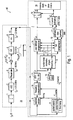
- the diagram of the interesting blocks of analysing device 40 is shown in fig. 1.
- First the RF signal is downconverted to the intermediate IF frequency, e.g. f IF 20.4 MHz.
- the resulting IF signal r IF ( t ) is shown on the left-hand side of fig. 1.
- ADC analog to digital converter
- the subsequent digital down converter 4 shifts the IF signal to the complex base band.
- the base band signal is filtered by a FIR filter 5.
- the subsequent digital signal processing is shown and designated as W-LAN application block 7.
- the packet search is performed.
- This block 8 detects the long symbol LS and recovers the timing.
- the coarse timing is detected first.
- This search is preferably implemented in the time domain.
- a coarse estimate ⁇ f and coarse of the receiver-transmitter Rx-Tx frequency offset ⁇ f is derived from the metric. This can easily be understood because the phase of r ( i ) ⁇ r* ( i+N ) is determined by the frequency offset. As the frequency deviation ⁇ f can exceed half a bin (distance between neighbour sub-carriers) the preceding short symbol SS is also analysed in order to detect the ambiguity.
- the position of the long symbol LS is known and the starting point of the useful part of the first payload symbol can be derived.
- this calculated time instant is used to position the payload window. Only the payload part is windowed. This is sufficient because the payload is the only subject of the subsequent measurements.
- the windowed sequence is compensated by the coarse frequency estimate ⁇ f and coarse . This is necessary because otherwise inter channel interference (ICI) would occur in the frequency domain.
- ICI inter channel interference
- the transition to the frequency domain is achieved by an fast fourier transform FFT of e.g. length 64 in block 11.
- FFT is performed symbolwise for everyone of the nof_symbols symbols of the payload.
- AWGN additive white Gaussian noise
- N s 80 of the symbol period
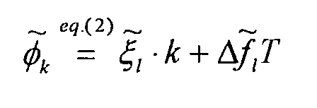
- phase drift ⁇ k phase drift within one useful part of the symbol
- ⁇ k the relative clock deviation of the reference oscillator
- ⁇ f the (not yet compensated) frequency deviation
- both the phase drift ⁇ k caused by the not yet compensated frequency deviation ⁇ f and the clock deviation ⁇ may not be neglected.
- ⁇ max 20 ppm.
- nof _ symbols 400 symbols is assumed.
- the example shows that it is also necessary to estimate and compensate the clock deviation, which is accomplished in the estimation block 12 using pilot table 13 and in the compensation blocks 14 and 15.
- the FFT must be followed by the joint estimation of the gain g , the fine frequency deviation ⁇ f and the clock deviation ⁇ .
- the tracking of the gain g is supported symbol for symbol.
- the coarse channel transfer function H and ( coarse ) / k is calculated. This is useful because before symbol estimation the sequence r' l,k is compensated by the coarse channel transfer function H and ( coarse ) / k . Consequently a potential change of the gain at the symbol l (caused, for example, by the increase of DUT amplifier temperature) would increase the symbol error rate especially at large symbol alphabet M of the MQAM transmission. In this case the estimation and the subsequent compensation of the gain is useful. In the subsequent formulas the gain at the symbol l will be described by the parameter g l .
- the optimum maximum likelihood algorithm is used. Consequently, the log likelihood function with is calculated as a function of the trial parameters , and . Finally, the trial parameters leading to the minimum of the log likelihood function are used as estimates , ⁇ f and l and ⁇ and l .
- the known pilot symbols a l,k are read from table 13. It can be shown that the search procedure is independent of the frequency response H k (see eq. (3)). Therefore, only the current r l,k and a l,k are required. This robust algorithm even works well at low signal to noise ratios of about 5 dB with the Cramer Rao Bound being reached.
- the sequence r l , k is compensated in the compensation blocks 14 and 15.
- the compensation is user-defined i.e. the user determines which of the three parameters are compensated in compensation block 14. This is useful in order to extract the influence of these parameters.
- the resulting output sequence is described by r' l,k .
- the full compensation is always performed in compensation block 15. This separate compensation is necessary in order to avoid symbol errors.
- the secure estimation of the data symbols â l , k is performed. From equation (1) it is clear that first the channel transfer function H k must be removed. This is achieved by dividing the known coarse channel estimate H and ( coarse ) / k calculated from the LS. Usually an error free estimation of the data symbols can be assumed.
- r' l,k is divided by the improved estimates H and k .
- the resulting channel compensated sequence is described by r'' l,k .
- the measurement variables are calculated.
- the most important variable is the error vector magnitude of the sub-carrier k of the current packet.
- the packet error vector magnitude is derived by averaging the squared EVM k versus k .
- the average error vector magnitude is calculated by averaging the packet EVM of all nof_packets detected packets. This parameter is equivalent to the so-called "RMS average of all errors Error RMS " of the IEEE802.11a measurement commandment, see IEEE W-LAN Standard, Chapter 17.3.9.7.
- Fig. 1 describes the W-LAN signal processing using a wideband signal section 20, such as Rohde & Schwarz device FSQ.
- the available bandwidth of the FSQ is 27 MHz and therefore sufficient to measure the IEEE802.11a signal with a bandwidth of 16.4 MHz.
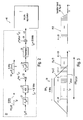
- fig. 2 the diagram of the interesting blocks of signal section 20 is shown.
- the IF signal is not yet bandlimited.
- the bandwidth 8 W A of signal section 20 of 8 MHz is modelled by the subsequent IF filter 21 with the frequency transfer function H IF ( f ).
- the schematic spectrum R IF ( f ) of the input signal is shown in fig. 3.
- the bandwidth BW OFDM of the spectrum of the OFDM signal and the reduced bandwidth BW A of the analysing device 40 are indicated in fig. 3.
- the schematic transfer function H IF ( f ) is shown in fig. 3.
- the passband bandwidth BW A of the example is 8 MHz and symmetric to the IF frequency.
- the sub-carriers in the undistorted passband will be analysed.
- the main task of the IF filter 21 is to avoid aliasing effects in the 8 MHz analysing window by the subsequent sampling process of the Analog to Digital Converter (ADC) 22.
- This complex multiplication effects a spectral shift from the IF frequency f IF to base band.
- the following low pass filter 24 with the transfer function H LP ( f ) also possesses the passband bandwidth of 8 MHz, see schematic plot in fig. 3, and fulfils two tasks:
- sampling must be changed to the Nyquist rate.
- This is performed by a digital resampler 25.
- the resampled sequence is multiplied with the sequence e - j ⁇ offset ⁇ iT s 2 in multiplier 26.
- This operation generates a further spectral shift by the frequency f offset .
- This spectral shift can be integrated in the first downconversion, if the resampling process does not require a low pass input sequence.
- the resulting output sequence is r ( i ).
- the sequence r ( i ) enters into the W-LAN application 7 which is identical to the wideband FSQ implementation shown in fig. 1. Thus reference is made to the lower part of fig. 1.
- the length ⁇ of the impulse response h ( t ) the low pass filter 24 is shorter than the length T GA of the guard periods of the data symbols.
- T GA the length of the guard periods of the data symbols.
- the impulse response h ( t ) of low pass filter 24 has a specific length ⁇ .
- ⁇ There are several possibilities to define the length ⁇ of the impulse response h ( t ).
- One possibility is illustrated in fig. 5.
- the impulse response h ( t ) decreases from starting value A to value 1/e ⁇ A within the time period ⁇ which can be used as a definition of the length ⁇ of the impulse response h(t).
- the length ⁇ of the impulse response of low pass filter 24 is defined as the inverse 1/ BW A of the bandwidth BW A of the low pass filter 24.
- ISI inter symbol interference
- this bandlimited measurement supports symbolwise tracking. This is possible because there are according to the invention always 2 pilot sub-carriers of the total 4 pilot sub-cariers within the 8 MHz analysing window.
- the pilots are used for symbolwise tracking, i.e. optional phase and/or timing and/or gain.
- the smaller number of used pilot carriers (2 instead of usually 4) leads to a higher estimation error of the synchronisation parameters ⁇ f and l , ⁇ and l and consequently to an increase of the EVM compared to a measurement with no limitation of the bandwidth.
- the statistical increase can be calculated however and can be compensated by averaging the synchronisation parameters ⁇ f and l , ⁇ and l over several data symbols.
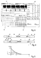
- Fig. 6 shows a typical screen plot of an analysing device 40.
- Section 41 shows the bursts of a specific sub-carrier of the OFDM signal.
- Section 42 shows the constellation diagram on a specific sub-carrier.
- Section 43 indicates EVM of all carriers, of the data carriers, the pilot carriers and the free carriers. Further, the IQ-Offset, IQ-Imbalance and quadrature mismatch are shown.
- Section 44 shows a diagram with EVM as a function of the sub-carrier number.
Landscapes
- Engineering & Computer Science (AREA)
- Computer Networks & Wireless Communication (AREA)
- Signal Processing (AREA)
- Digital Transmission Methods That Use Modulated Carrier Waves (AREA)
- Mobile Radio Communication Systems (AREA)
Abstract
Description
- Fig. 1
- shows the block diagram of a conventional analysing device;
- Fig. 2
- shows the block diagram of an inventive analysing device;
- Fig. 3
- shows the spectrum of the OFDM signal and the
reduced bandwidth of
signal section 20 of the inventive analysing device; - Fig. 4
- shows a symbol sequence of one channel of the OFDM signal with the useful part and the guard period;
- Fig. 5
- shows a schematic diagram of impulse response of
low pass filter 24 and - Fig. 6
- shows an example of the screen of the analysing device with specific diagrams.
- al,k
- symbol l of sub-carrier k
- EVMk
- error vector magnitude of sub-carrier k
- EVM
- error vector magnitude of current packet
- Δf
- frequency deviation between transmitter Tx and receiver Rx
- l
- symbol index l = [l, nof_Symbols]
- nof _symbols
- number of symbols of payload
- Hk
- channel transfer function of sub-carrier k
- k
- channel index k = [-31,32]
- Kmod
- modulation dependant normalisation factor
- ξ
- relative clock error of reference oscillator
- rl,k
- sub-carrier k of symbol l

the modulation-dependant normalisation factor K mod,
the symbol al , k of sub-carrier k at symbol l,
the channel frequency response Hk ,
the phase drift k of sub-carrier k within one useful part of the symbol T (see below),
the number of Nyquist samples, e.g. Ns = 80 of the symbol period,
the number of Nyquist samples, e.g. N = 64 of the useful part of the symbol and
the independent Gaussian distributed noise samples nl,k .
ξ = the relative clock deviation of the reference oscillator and
Δf = the (not yet compensated) frequency deviation.



- fIF
- IF frequency
- fbin
- frequency distance between neighbour sub-carriers
- H...(f)
- filter transfer function
- i
- time index of the sampled sequence
- k
- channel index of occupied sub-carriers k = [-26,26]
- Ts=1/fs
- sample period and frequency respectively
- About 20 of the 52 sub-carriers can be analysed within a measurement.
- The position of the analysing window can be selected by the operator, e.g. to analyse the left, the middle or the right sub-carriers.
- Also symbolwise tracking of timing, phase and gain is supported.
- Suppression of the mirror at f = -2fIF caused by the spectral shift.
- The
low pass filter 24 must avoid aliasing effects in the e.g. 8MHz analysing window 39 caused by the subsequent resampling process. As the resampling process reduces the sample rate, the transition band atlow pass filter 24 must be steeper compared to theIF filter 21.
Claims (13)
- Method for analysing an OFDM signal (rIF (t)) transporting a series of data symbols (S1, S2, ...) on several orthogonal carrier frequencies with an analysing device (40) having a signal section (20) with a bandwidth (BWA ) smaller than the bandwidth (BWOFDM ) of the OFDM signal, whereby a first specific number of carrier frequencies transport a pilot signal within the OFDM signal,
comprising the steps of low pass filtering of the OFDM signal with a low pass filter (24) and shifting (26) the spectrum of the OFDM signal in order to obtain a frequency shifted filtered OFDM signal (r(i)), and estimating (12) several synchronisation parameters (Δf andl ,ξ and l ) of the OFDM signal by use of the pilot signal,
whereby the number of useful carrier frequencies transporting the pilot signal is reduced to a second specific number by the signal section (20) with its bandwidth (BWA ) smaller than the bandwidth (BWOFDM ) of the OFDM signal and
averaging (12) the estimated synchronisation parameters (Δf andl ,ξ and l ) of the OFDM signal over several data symbols in order to compensate the reduced number of useful carrier frequencies transporting the pilot signal. - Method according to claim 1,
characterised in that
the first specific number is 4 and the second specific number is 2. - Method according to claim 1 or 2,
characterised in that
the estimated characteristic values of the OFDM signal are symbolwise frequency offset (Δf andl ) and/or clock offset (ξ and l ) and/or phase offset resulting therefrom and/or gain (g andl ). - Method according to any of claims 1 to 3,
characterised in that
each data symbol (S1) has a useful part (30) separated by a guard period (31) from neighbouring data symbols (S2), whereby the length (τ) of the impulse response (h(t)) of the low pass filter (24) is shorter than the length (TGP ) of the guard periods (31) of the data symbols (S1, S2, ...) . - Method according to claim 4,
characterised in that
the length (τ) of the impulse response (h(t)) of the low pass filter (24) is shorter than ¼ of the length of the guard periods (31) of the data symbols (S1, S2, ...). - Method according to any of claims 1 to 5,
characterised in that
the estimation of the synchronisation parameters is done for each symbol of the pilot signal and is averaged over several symbols. - Method according to claim 6,
characterised in that
the length (τ) of the impulse response (h(t)) of the low pass filter (24) is about 2.5/16 of the length of the guard periods (31) of the data symbols (S1, S2, ...). - Method according to any of claims 1 to 7,
characterised in that
the OFDM signal is resampled (25) after low pass filtering (24). - Analysing device (40) for analysing an OFDM signal (rIF (t)) transporting a series of data symbols (S1, S2, ...) on several orthogonal carrier frequencies,
whereby the analysing device (40) has a signal section (20) with a bandwidth (BWA ) smaller than the bandwidth (BWOFDM ) of the OFDM signal within the OFDM signal,
whereby a first specific number of carrier frequencies transport a pilot signal,
whereby the analysing device (40) has a low pass filter (24) for low pass filtering of the OFDM signal and a frequency shifter (26) for shifting the spectrum of the OFDM signal in order to obtain a frequency shifted filtered OFDM signal (r(i)), and estimating means (12) for estimating several synchronisation parameters (Δf andl ,ξ and l ) of the OFDM signal by use of the pilot signal,
whereby the number of carrier frequencies transporting the pilot signal is reduced to a second specific number by the signal section (20) with its bandwidth (BWA ) smaller than the bandwidth (BWOFDM ) of the OFDM signal and
whereby the estimating means (12) averages the estimated synchronisation parameters (Δf andl,ξ and l ) of the OFDM signal over several data symbols l in order to compensate the reduced number of carrier frequencies transporting the pilot signal. - Digital storage medium with control signals electronically readable from the digital storage medium, which interact with a programmable computer or digital signal processor in a manner that all steps of the method according to any of claims 1 to 8 can be performed.
- Computer-program-product with program-code-means stored on a machinereadable data carrier to perform all steps of any of claims 1 to 8, when the program is performed on a programmable computer or a digital signal processor.
- Computer program with programm-code-means to perform all steps of any of claims 1 to 8, when the program is performed on a programmable computer or a digital signal processor.
- Computer program with program-code-means to perform all steps of any of claims 1 to 8, when the program is stored on a machinereadable data carrier.
Priority Applications (1)
| Application Number | Priority Date | Filing Date | Title |
|---|---|---|---|
| EP04000541A EP1447952B1 (en) | 2002-12-09 | 2003-03-03 | Method and device for analysing an OFDM signal |
Applications Claiming Priority (4)
| Application Number | Priority Date | Filing Date | Title |
|---|---|---|---|
| EP02027409 | 2002-12-09 | ||
| EP02027409 | 2002-12-09 | ||
| EP03004669A EP1445906B1 (en) | 2002-12-09 | 2003-03-03 | Method and device for analysing an OFDM signal |
| EP04000541A EP1447952B1 (en) | 2002-12-09 | 2003-03-03 | Method and device for analysing an OFDM signal |
Related Parent Applications (2)
| Application Number | Title | Priority Date | Filing Date |
|---|---|---|---|
| EP03004669.2 Division | 2003-03-03 | ||
| EP03004669A Division EP1445906B1 (en) | 2002-12-09 | 2003-03-03 | Method and device for analysing an OFDM signal |
Publications (2)
| Publication Number | Publication Date |
|---|---|
| EP1447952A1 true EP1447952A1 (en) | 2004-08-18 |
| EP1447952B1 EP1447952B1 (en) | 2011-06-22 |
Family
ID=32658180
Family Applications (2)
| Application Number | Title | Priority Date | Filing Date |
|---|---|---|---|
| EP04000541A Expired - Lifetime EP1447952B1 (en) | 2002-12-09 | 2003-03-03 | Method and device for analysing an OFDM signal |
| EP03004669A Expired - Lifetime EP1445906B1 (en) | 2002-12-09 | 2003-03-03 | Method and device for analysing an OFDM signal |
Family Applications After (1)
| Application Number | Title | Priority Date | Filing Date |
|---|---|---|---|
| EP03004669A Expired - Lifetime EP1445906B1 (en) | 2002-12-09 | 2003-03-03 | Method and device for analysing an OFDM signal |
Country Status (3)
| Country | Link |
|---|---|
| US (1) | US7492700B2 (en) |
| EP (2) | EP1447952B1 (en) |
| JP (1) | JP4359492B2 (en) |
Families Citing this family (20)
| Publication number | Priority date | Publication date | Assignee | Title |
|---|---|---|---|---|
| IL159173A0 (en) * | 2003-12-03 | 2004-06-01 | Zion Hadad | Ofdm communication channel |
| DE602004016295D1 (en) * | 2004-05-27 | 2008-10-16 | Synad Technologies Ltd | A method for determining true error vector size in a wireless local area network |
| US7769372B1 (en) * | 2004-07-08 | 2010-08-03 | National Semiconductor Corporation | Selectively activated multi-subcarrier (SAMS) radio transceiver measuring techniques |
| US8325863B2 (en) * | 2004-10-12 | 2012-12-04 | Qualcomm Incorporated | Data detection and decoding with considerations for channel estimation errors due to guard subbands |
| US7751470B2 (en) * | 2005-02-07 | 2010-07-06 | Tektronix, Inc. | Time correlation of signal power to distortion characteristics |
| US8675631B2 (en) * | 2005-03-10 | 2014-03-18 | Qualcomm Incorporated | Method and system for achieving faster device operation by logical separation of control information |
| US20100157833A1 (en) * | 2005-03-10 | 2010-06-24 | Qualcomm Incorporated | Methods and systems for improved timing acquisition for varying channel conditions |
| US20060221810A1 (en) * | 2005-03-10 | 2006-10-05 | Bojan Vrcelj | Fine timing acquisition |
| US8175123B2 (en) * | 2005-03-10 | 2012-05-08 | Qualcomm Incorporated | Collection window positioning using time tracking information |
| EP1727324A1 (en) * | 2005-05-25 | 2006-11-29 | Siemens Aktiengesellschaft | Radio transmission with guard interval of variable length |
| KR100699490B1 (en) * | 2005-08-22 | 2007-03-26 | 삼성전자주식회사 | Sampling Frequency Offset Estimation Method and OPM System to which the Method is Applied |
| US7706250B2 (en) | 2005-09-23 | 2010-04-27 | Litepoint Corp. | Apparatus and method for simultaneous testing of multiple orthogonal frequency division multiplexed transmitters with single vector signal analyzer |
| US7822130B2 (en) * | 2005-09-23 | 2010-10-26 | Litepoint Corporation | Apparatus and method for simultaneous testing of multiple orthogonal frequency division multiplexed transmitters with single vector signal analyzer |
| US7623607B2 (en) * | 2005-10-31 | 2009-11-24 | Qualcomm Incorporated | Methods and apparatus for determining timing in a wireless communication system |
| US8948329B2 (en) * | 2005-12-15 | 2015-02-03 | Qualcomm Incorporated | Apparatus and methods for timing recovery in a wireless transceiver |
| US8345804B2 (en) * | 2007-06-14 | 2013-01-01 | Alcatel Lucent | Simplified RACH preamble detection receiver |
| US8139527B2 (en) | 2007-12-19 | 2012-03-20 | Wi-Lan, Inc. | Wireless system with reduced effect of IQ imbalance |
| JP2011525758A (en) * | 2008-07-07 | 2011-09-22 | 聯發科技股▲ふん▼有限公司 | Data transmission / reception method and communication apparatus using the same in multiband orthogonal frequency division multiple access (OFDMA) communication system |
| CN102946253B (en) * | 2012-10-23 | 2016-06-08 | 保定市三川电气有限责任公司 | Data sampling method and system and the application process in parameter identification thereof and system |
| CN106383512B (en) * | 2016-10-10 | 2019-02-01 | 中国科学技术大学 | A kind of electromagnetic protection reinforcement method of DSP control system |
Citations (4)
| Publication number | Priority date | Publication date | Assignee | Title |
|---|---|---|---|---|
| US4896102A (en) | 1988-06-13 | 1990-01-23 | Scientific-Atlanta, Inc. | Spectrum analyzer |
| US5475707A (en) * | 1994-02-28 | 1995-12-12 | Westinghouse Norden Systems | Broadband communications system |
| EP1193934A2 (en) * | 2000-09-29 | 2002-04-03 | Samsung Electronics Co., Ltd. | Frequency offset correction in multicarrier receivers |
| EP1206096A2 (en) * | 2000-11-09 | 2002-05-15 | Sony United Kingdom Limited | Symbol synchronisation in a multicarrier receiver |
Family Cites Families (5)
| Publication number | Priority date | Publication date | Assignee | Title |
|---|---|---|---|---|
| US6359938B1 (en) * | 1996-10-31 | 2002-03-19 | Discovision Associates | Single chip VLSI implementation of a digital receiver employing orthogonal frequency division multiplexing |
| JP3535344B2 (en) * | 1997-05-30 | 2004-06-07 | 松下電器産業株式会社 | Multicarrier transmission method, data transmission device, mobile station device, and base station device |
| US6772181B1 (en) * | 1999-10-29 | 2004-08-03 | Pentomics, Inc. | Apparatus and method for trigonometric interpolation |
| US6747946B1 (en) * | 1999-12-27 | 2004-06-08 | Victor Company Of Japan, Ltd. | Method and apparatus for transmitting orthogonal-multi-carrier signal |
| CA2390253A1 (en) * | 2001-06-11 | 2002-12-11 | Unique Broadband Systems, Inc. | Ofdm multiple sub-channel communication system |
-
2003
- 2003-03-03 EP EP04000541A patent/EP1447952B1/en not_active Expired - Lifetime
- 2003-03-03 EP EP03004669A patent/EP1445906B1/en not_active Expired - Lifetime
- 2003-11-12 US US10/712,766 patent/US7492700B2/en active Active
- 2003-12-09 JP JP2003410974A patent/JP4359492B2/en not_active Expired - Fee Related
Patent Citations (4)
| Publication number | Priority date | Publication date | Assignee | Title |
|---|---|---|---|---|
| US4896102A (en) | 1988-06-13 | 1990-01-23 | Scientific-Atlanta, Inc. | Spectrum analyzer |
| US5475707A (en) * | 1994-02-28 | 1995-12-12 | Westinghouse Norden Systems | Broadband communications system |
| EP1193934A2 (en) * | 2000-09-29 | 2002-04-03 | Samsung Electronics Co., Ltd. | Frequency offset correction in multicarrier receivers |
| EP1206096A2 (en) * | 2000-11-09 | 2002-05-15 | Sony United Kingdom Limited | Symbol synchronisation in a multicarrier receiver |
Non-Patent Citations (3)
| Title |
|---|
| "Medium class aspiring to high end", NEWS FROM ROHDE&SCHWARZ, no. 166, 19 November 2001 (2001-11-19), pages 4 - 7, XP002284149, Retrieved from the Internet <URL:http://www.rohde-schwarz.com/test_and_measurement/spectrum_analysis/fsp/> [retrieved on 20040610] * |
| "Signal Analyzer R&S FSQ", ROHDE&SCHWARZ, 15 July 2002 (2002-07-15), pages 1 - 17, XP002284148, Retrieved from the Internet <URL:http://www.rohde-schwarz.com/test_and_measurement/spectrum_analysis/fsq/> [retrieved on 20040610] * |
| CLASSEN F ET AL: "SYNCHRONIZATION ALGORITHMS FOR AN OFDM SYSTEM FOR MOBILE COMMUNICATION", CODIERUNG FUR QUELLE, KANAL UND UBERTRAGUNG. VORTRAGE DER ITG-FACHTAGUNG, no. 130, 26 October 1994 (1994-10-26) - 28 October 1994 (1994-10-28), ITG FACHBERICHTE, BERLIN, VDE VERLAG, DE, pages 105 - 113, XP000503783, ISBN: 3-8007-2036-1 * |
Also Published As
| Publication number | Publication date |
|---|---|
| EP1447952B1 (en) | 2011-06-22 |
| US20040125742A1 (en) | 2004-07-01 |
| JP2004194327A (en) | 2004-07-08 |
| EP1445906A1 (en) | 2004-08-11 |
| JP4359492B2 (en) | 2009-11-04 |
| US7492700B2 (en) | 2009-02-17 |
| EP1445906B1 (en) | 2006-05-31 |
Similar Documents
| Publication | Publication Date | Title |
|---|---|---|
| EP1445906A1 (en) | Method and device for analysing an OFDM signal | |
| US6757344B2 (en) | Apparatus and method for measuring sub-carrier frequencies and sub-carrier frequency offsets | |
| US7453792B2 (en) | Receiver architecture for pilot based OFDM systems | |
| US8526518B2 (en) | Imbalance compensation for direct conversion communication systems | |
| Stantchev et al. | Time-variant distortions in OFDM | |
| KR100770924B1 (en) | Frequency Error Compensation Device and Method in Wireless Communication System | |
| CA2672460C (en) | Location of wideband ofdm transmitters with limited receiver bandwidth | |
| EP2545691B1 (en) | Frequency-dependent IQ imbalance estimation | |
| KR101468514B1 (en) | Methods and an apparatus for estimating a residual frequency error in a communications system | |
| EP1313283A2 (en) | Timing synchronization for OFDM-based wireless networks | |
| EP2290893A1 (en) | Frequency Synchronization in OFDM Receiver using sliding Fourier Transform | |
| Petrovic et al. | Common phase error due to phase noise in OFDM-estimation and suppression | |
| US7724804B2 (en) | Receiving apparatus and channel estimating apparatus | |
| Yan et al. | Carrier frequency offset estimation and I/Q imbalance compensation for OFDM systems | |
| Yan et al. | Carrier frequency offset estimation for OFDM systems with I/Q imbalance | |
| Piemontese et al. | Phase noise in communication systems: from measures to models | |
| Son et al. | Tackling the Coupled Frequency Offset Impairments for IEEE 802.11 be Wideband WLANs | |
| WO2009053150A2 (en) | Method and apparatus for reducing phase noise in orthogonal frequency division multiplexing systems | |
| JP2002232389A (en) | OFDM receiver | |
| US20080298489A1 (en) | Method for estimating the characteristcs of ofdm signals | |
| Miaoudakis et al. | Carrier frequency offset estimation and correction for Hiperlan/2 WLANs | |
| DE60305632T2 (en) | Method and apparatus for analyzing an OFDM signal | |
| Hwang et al. | A highly re-configurable Instruments-in-Matlab Software-Defined Radio platform for 4G SC-FDMA signal measurements and analysis | |
| JP2004088662A (en) | Method and apparatus for detecting symbol synchronization timing in orthogonal multicarrier signal transmission system | |
| Granado et al. | A new method for simultaneous fine time synchronization and frequency offset estimation in OFDM with simple hardware |
Legal Events
| Date | Code | Title | Description |
|---|---|---|---|
| PUAI | Public reference made under article 153(3) epc to a published international application that has entered the european phase |
Free format text: ORIGINAL CODE: 0009012 |
|
| 17P | Request for examination filed |
Effective date: 20040113 |
|
| AC | Divisional application: reference to earlier application |
Ref document number: 1445906 Country of ref document: EP Kind code of ref document: P |
|
| AK | Designated contracting states |
Kind code of ref document: A1 Designated state(s): AT BE BG CH CY CZ DE DK EE ES FI FR GB GR HU IE IT LI LU MC NL PT RO SE SI SK TR |
|
| AX | Request for extension of the european patent |
Extension state: AL LT LV MK |
|
| AKX | Designation fees paid |
Designated state(s): DE GB |
|
| RBV | Designated contracting states (corrected) |
Designated state(s): DE GB |
|
| 17Q | First examination report despatched |
Effective date: 20050801 |
|
| GRAP | Despatch of communication of intention to grant a patent |
Free format text: ORIGINAL CODE: EPIDOSNIGR1 |
|
| GRAS | Grant fee paid |
Free format text: ORIGINAL CODE: EPIDOSNIGR3 |
|
| GRAA | (expected) grant |
Free format text: ORIGINAL CODE: 0009210 |
|
| AC | Divisional application: reference to earlier application |
Ref document number: 1445906 Country of ref document: EP Kind code of ref document: P |
|
| AK | Designated contracting states |
Kind code of ref document: B1 Designated state(s): DE GB |
|
| REG | Reference to a national code |
Ref country code: GB Ref legal event code: FG4D |
|
| REG | Reference to a national code |
Ref country code: DE Ref legal event code: R096 Ref document number: 60337521 Country of ref document: DE Effective date: 20110811 |
|
| PLBE | No opposition filed within time limit |
Free format text: ORIGINAL CODE: 0009261 |
|
| STAA | Information on the status of an ep patent application or granted ep patent |
Free format text: STATUS: NO OPPOSITION FILED WITHIN TIME LIMIT |
|
| 26N | No opposition filed |
Effective date: 20120323 |
|
| REG | Reference to a national code |
Ref country code: DE Ref legal event code: R097 Ref document number: 60337521 Country of ref document: DE Effective date: 20120323 |
|
| PGFP | Annual fee paid to national office [announced via postgrant information from national office to epo] |
Ref country code: DE Payment date: 20180316 Year of fee payment: 16 Ref country code: GB Payment date: 20180326 Year of fee payment: 16 |
|
| REG | Reference to a national code |
Ref country code: DE Ref legal event code: R119 Ref document number: 60337521 Country of ref document: DE |
|
| GBPC | Gb: european patent ceased through non-payment of renewal fee |
Effective date: 20190303 |
|
| PG25 | Lapsed in a contracting state [announced via postgrant information from national office to epo] |
Ref country code: GB Free format text: LAPSE BECAUSE OF NON-PAYMENT OF DUE FEES Effective date: 20190303 Ref country code: DE Free format text: LAPSE BECAUSE OF NON-PAYMENT OF DUE FEES Effective date: 20191001 |