EP1447927A1 - Signal processing apparatus and method - Google Patents
Signal processing apparatus and method Download PDFInfo
- Publication number
- EP1447927A1 EP1447927A1 EP03290388A EP03290388A EP1447927A1 EP 1447927 A1 EP1447927 A1 EP 1447927A1 EP 03290388 A EP03290388 A EP 03290388A EP 03290388 A EP03290388 A EP 03290388A EP 1447927 A1 EP1447927 A1 EP 1447927A1
- Authority
- EP
- European Patent Office
- Prior art keywords
- signal
- channel
- paths
- determined
- radio communications
- Prior art date
- Legal status (The legal status is an assumption and is not a legal conclusion. Google has not performed a legal analysis and makes no representation as to the accuracy of the status listed.)
- Withdrawn
Links
- 238000000034 method Methods 0.000 title claims abstract description 42
- 238000012545 processing Methods 0.000 title claims description 19
- 238000004891 communication Methods 0.000 claims abstract description 67
- 230000000694 effects Effects 0.000 claims abstract description 32
- 239000011159 matrix material Substances 0.000 claims abstract description 24
- 230000002596 correlated effect Effects 0.000 claims abstract description 16
- 238000007493 shaping process Methods 0.000 claims abstract description 10
- 238000001228 spectrum Methods 0.000 claims description 20
- 230000008569 process Effects 0.000 claims description 15
- 230000000875 corresponding effect Effects 0.000 claims description 9
- 230000007704 transition Effects 0.000 claims description 7
- 238000004590 computer program Methods 0.000 claims description 4
- 230000009466 transformation Effects 0.000 abstract description 18
- 230000001131 transforming effect Effects 0.000 abstract 1
- 230000007480 spreading Effects 0.000 description 17
- 238000005562 fading Methods 0.000 description 13
- 238000004088 simulation Methods 0.000 description 13
- 238000010586 diagram Methods 0.000 description 10
- 230000001934 delay Effects 0.000 description 7
- 230000005540 biological transmission Effects 0.000 description 4
- 238000012937 correction Methods 0.000 description 3
- 238000004364 calculation method Methods 0.000 description 2
- 230000000670 limiting effect Effects 0.000 description 2
- 230000009467 reduction Effects 0.000 description 2
- 230000004044 response Effects 0.000 description 2
- 230000002441 reversible effect Effects 0.000 description 2
- 238000005070 sampling Methods 0.000 description 2
- 239000000654 additive Substances 0.000 description 1
- 230000000996 additive effect Effects 0.000 description 1
- 238000013459 approach Methods 0.000 description 1
- 238000005311 autocorrelation function Methods 0.000 description 1
- 230000008901 benefit Effects 0.000 description 1
- 239000002131 composite material Substances 0.000 description 1
- 230000003111 delayed effect Effects 0.000 description 1
- 238000001914 filtration Methods 0.000 description 1
- 238000013507 mapping Methods 0.000 description 1
- 238000005259 measurement Methods 0.000 description 1
- 238000012986 modification Methods 0.000 description 1
- 230000004048 modification Effects 0.000 description 1
- 230000000135 prohibitive effect Effects 0.000 description 1
- 230000003252 repetitive effect Effects 0.000 description 1
- 230000002123 temporal effect Effects 0.000 description 1
Images





Classifications
-
- H—ELECTRICITY
- H04—ELECTRIC COMMUNICATION TECHNIQUE
- H04B—TRANSMISSION
- H04B17/00—Monitoring; Testing
- H04B17/30—Monitoring; Testing of propagation channels
- H04B17/391—Modelling the propagation channel
- H04B17/3912—Simulation models, e.g. distribution of spectral power density or received signal strength indicator [RSSI] for a given geographic region
-
- H—ELECTRICITY
- H04—ELECTRIC COMMUNICATION TECHNIQUE
- H04B—TRANSMISSION
- H04B1/00—Details of transmission systems, not covered by a single one of groups H04B3/00 - H04B13/00; Details of transmission systems not characterised by the medium used for transmission
- H04B1/69—Spread spectrum techniques
- H04B1/707—Spread spectrum techniques using direct sequence modulation
- H04B1/7097—Interference-related aspects
- H04B1/711—Interference-related aspects the interference being multi-path interference
- H04B1/7115—Constructive combining of multi-path signals, i.e. RAKE receivers
Definitions
- the present invention relates to signal processing apparatus and methods for representing the effects of radio communications channels.
- Data is communicated using radio signals by modulating a radio frequency signal with the data in some way.
- the radio frequency signal propagates from a transmitting antenna and is detected by a receiving antenna.
- An estimation of the communicated data is then recovered by de-modulating the received radio signal.
- Radio communications channels associated with mobile radio systems are characterised by including a number of multi-path rays with distinct propagation delays.
- Each path represents the propagation of a version of a radio signal from a transmitter to a receiver. It is known that the amplitude of each version of the radio signal received via each of the paths can be represented as zero mean complex gaussian random variable.
- the multi-path versions combine to form a composite signal. If the difference between the respective delays for each path exceeds a symbol period of the communicated data, then inter-symbol interference occurs, which must be corrected in order for data to be communicated.
- receiver techniques are arranged to recover data in the presence of multi-path propagation.
- a complex gaussian random variable is generated for each path and for each sample of the simulated radio signal. Therefore, the simulation of such multi-path channels can represent a substantial computational task, requiring a relatively long time to generate simulation results representing the performance of a radio communications receiver. In particular, but not exclusively, a time taken to simulate spread spectrum communications can be prohibitively long. This is because a spread spectrum signal is formed by arranging for the data to be communicated to modulate a spreading code.
- the spreading code includes a much greater number of bits, referred to as chips, than the data being communicated.
- Examples of communications techniques which might be simulated, include channel coding techniques such as forward error correction encoding and decoding.
- channel coding techniques such as forward error correction encoding and decoding.
- the orthogonalisation technique only provides a facility for obtaining a bounded performance for channel coding techniques, whereas a more exact performance representing the time correlation effects of the radio channel is preferable.
- a signal processing apparatus operable to represent the effects on a received signal of a radio communications channel having L paths. Each path has an average attenuation and a pre-determined respective delay.
- the received signal includes a combination of correlated components determined from an effect of pulse shaping filters on the received signal, each correlated component having a correlation coefficient representing a correlation of the received signal component with respect to each of the other components.
- the signal processing apparatus comprises a plurality of signal simulators, each simulator generating a signal component value proportional to a complex zero mean gaussian random variable having a pre-determined variance.
- the signal processing apparatus includes a summer operable to sum the signal component values produced from each signal simulator, to form a representation of the signal received via the radio communications channel.
- the variance of each of the signal simulators is pre-determined by calculating the eigen values of a matrix formed from the correlation coefficients and from a channel correlation matrix which includes the average attenuation of each of the L paths.
- Embodiments of the present invention can provide simulators for radio communications channels, which can represent the radio communications channel with a substantially reduced complexity with respect to known simulators.
- the reduction in complexity is achieved by performing a transformation of a conventional representation of a radio communications channel having L paths and L correlation coefficients.
- the radio communications channel may not only be simulated with substantially reduced complexity but also removes a requirement for representing the correlation between correlated components from which the received signal is formed.
- the number of signal simulators may be less than the number of paths L of the radio communications channel being simulated.
- the number of signal simulators is determined from the number of eigen values above a pre-determined threshold, each eigen value above the threshold forming the pre-determined variance for a corresponding signal simulator.
- the correlation coefficients representing a correlation between each correlated component with respect to each of the other components, may represent a correlation between the output of each correlator of a rake receiver.
- CDMA Code Division Muliple Access
- a rake receiver is often used to recover data from a spread spectrum signal.
- Each correlator of the rake receiver correlates the received signal with respect to a spreading code at a pre-determined delay.
- the output of each rake correlator may be correlated with respect to the outputs of the other correlators, the correlation being represented by the correlation coefficients.
- embodiments of the present invention are not limited to simulating CDMA communications.
- the separate components of the communicated signal may be formed Multiple Inputs Multiple Outputs (MIMO) communications or Time Division Multiple Access (TDMA).
- MIMO Multiple Inputs Multiple Outputs
- TDMA Time Division Multiple Access
- FIG. 1 Schematic block diagrams in Figures 1, 2 and 3 provide an illustration of a transformation providing a simplification of a simulated radio communications channel according to an embodiment of the present invention.
- a data source 1 generates data in digital form, which is fed to an encoder 2.
- the encoder 2 could apply any form of coding to the data generated from the source 1, such as error correction encoding.
- a spread spectrum encoder 3 then receives the encoded data, and generates a spread spectrum signal by modulating a spreading code with the encoded data.
- the spreading code is formed from a pseudo-random bit sequence having a non-repetitive period of one thousand or more bits, each bit of the modulated spreading code being known as a chip.
- the spread spectrum signal is then received by a modulator 4.
- the modulator modulates a base band carrier signal with the chips of the spread spectrum signal.
- this might include some form of phase or amplitude modulation such a QPSK or QAM in which the phase and/or amplitude of the base band carrier signal is modulated with the encoded data.
- the signal from the modulator 4 is fed to a pulse shaping filter 6 which provides a bandwidth limiting effect which would be applied to the radio signal to be communicated before transmission.
- the pulse-shaping filter is typically in the form of a root raised cosine response so that by employing a corresponding root raised cosine filter at the receiver, an overall raised cosine response is produced. Accordingly by sampling the received data at the symbol time (which for a spread spectrum signal is the chip period), the effects of adjacent chips will be substantially zero at the sampling instant, thereby minimising inter-symbol interference which otherwise might be introduced by the band limiting filters.
- the base band modulated signal would be up converted to a radio frequency signal, amplified and transmitted from an appropriate antenna.
- the effects of the radio communications channel can be modelled by applying equivalent effects to the base band signal produced by the modulator 4.
- radio communications channels can be represented as a plurality of L discrete paths, each path providing an independently fading version of the radio signal being represented by a zero mean complex gaussian process also known as a Rayleigh fading process.
- the simulated transmitted signal passes from the pulse-shaping transmitter filter 6 to an anti-aliasing receiver filter 8, via an L-path Rayleigh fading channel 10 and a noise generator 12.
- the L-path Rayleigh fading channel 10 models the effects of a multi-path radio channel, the effects of noise which is introduced during transmission and is present at the receiver antenna (due to thermal noise) is provided by the noise generator 12.
- u is the signal before channel 10
- the signal after the noise generator 12 is with h i the complex channel coefficient and ⁇ i the delay for path i.
- AWGN stands for Additive White Gausssian Noise.
- the received signal is fed to a de-modulator 14, which produces an estimate of the spread spectrum encoded data produced by the spread spectrum encoder 3, by performing a reverse mapping of the data from the complex base band signal as was applied to the modulator 4.
- the received spread spectrum encoded data is then fed to a multi-path correlation receiver 16.
- the multi-path correlation receiver 16 recovers an estimate of the base band encoded data, by correlating the received demodulated data with a reproduced version of the spreading code which was used to form the transmitted signal by the spread spectrum encoder.
- the de-spread base band encoded data is then fed to a decoder 18, which forms a reverse of the encoding process to estimate the base band data.
- the estimation of the base band data may include correcting errors in the estimation of the received data, if the data has been encoded using an error correction code.
- the estimated base band data is then fed to a sink 20.
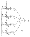
- FIG. 2 provides a more detailed representation of the multi-path correlation receiver, otherwise known as a rake receiver.
- the rake receiver 16 includes a plurality of L correlators 30, each of the correlators 30 receives on a first input 32 a version of the spreading code C n ( t ) which was used to spread the received data bearing spread spectrum signal in the spread spectrum encoder 3.
- C n t
- the received sampled signal is fed from the de-modulator.
- the samples of the received signal are multiplied by the corresponding samples of the spreading code at the chip rate.
- the result of being multiplied by the spreading code is summed by summers 36 to form, for each spread spectrum symbol, a de-spread sample, which is summed by a further summer 38.
- the further summer 38 forms a sample of the base band encoded data which is de-spread and has the effect of substantially reducing the inter symbol interference introduced by the multi-path fading channel.
- the spreading code is reproduced within the rake receiver 16.
- Each version of the spreading code fed on the respective inputs 32 for each correlator 30 is delayed with respect to the first correlator, by an amount which represents a likely temporal position of one of the paths of the L path channel. Accordingly, the delays of each of the spreading codes which are represented as corresponding shifts of the spreading code sequence, aim to reflect the distribution of energy introduced by the multi-path channel.
- a base band data symbols communicated from the output of the encoder 2, to the output r of the multi-path correlation receiver 18, may be represented by the following equation:
- Each of the L paths of the simulated multi-path channel have parameters ( ⁇ i , ⁇ i ) 0 ⁇ i ⁇ L , where ⁇ i is the average attenuation of path i with a delay ⁇ i .
- the received symbol r is determined for a transmitted symbol s from equation (1) in which X i is a complex zero-mean gaussian random variable of variance ⁇ i and ⁇ ij is the correlation between the correlators i and j of the rake receiver, the number of correlators in the rake receiver being L .
- the L -path multi-path fading channel 10 requires the generation of a complex gaussian sample per chip of the spread spectrum signal. As will be appreciated, this represents a substantial computational load, in terms of the number of computations per second. Accordingly, a time taken to simulate the communication of a base band symbol including spreading and de-spreading, with multi-path fading channel at the chip rate may be large and for some simulations prohibitive.
- Embodiments of the present invention provide a facility for reducing the number of computations required per second required to simulate a multi-path fading channel.
- the reduction in complexity according to an embodiment of the invention comprises introducing a transformation of a matrix of values representing the double summation expressed as equation (1) above. The transformation thereby provides a simplification of the channel model.
- the transformation comprises computing the eigen values ( ⁇ i ) 0 ⁇ i ⁇ L of a matrix formed according to the double summation of equation (1), which is ⁇ ( ⁇ ij ) 0 ⁇ i , j ⁇ L ⁇ K where K is the correlation matrix of the channel (channel correlation matrix). In the usual case of independent paths, it becomes ⁇ ( ⁇ ij ) 0 ⁇ i,j ⁇ L ⁇ Diag ⁇ ( ⁇ i ) 0 ⁇ i,j ⁇ L ⁇ .
- the schematic block diagram of Figure 1 becomes that shown in Figure 3, where the output of the rake receiver 16' according to the simplified parts shown within a box 50, becomes that expressed by the equation below:
- Y i is a complex zero-mean gaussian random variable of variance ⁇ i and there is no correlation component.
- the main embodiment of the present invention is therefore to replace the channel definition set ( ⁇ i , ⁇ i ) by ( ⁇ i , iT c ).
- a equivalent one which is adapted to the rate of the transmission we consider. It can be CDMA, TDMA (replacing the chips by symbols) or MIMO.
- the number of signal simulators N may be less than or equal to the number of paths L .
- the radio communications channel represented by the schematic block diagram shown in Figure 3 corresponds to that shown in Figure 1 and so only the differences between Figures 1 and 3 will be explained.
- equation (3) the multi-path Rayleigh fading channel is transformed, to form an equaivalent channel 10'.
- equation (3) A diagram providing an implementation of a signal processing apparatus for representing the parts in box 50 is shown in Figure 4.
- a plurality of N signal simulators 60 generate signal component values Y i in accordance with zero mean complex random gaussian processes having a variance ⁇ i .
- the component values are fed to data processors 62 which form the squared magnitude
- 2 the input data signal s is fed.
- the data signal is scaled by each of the signal component values by the multipliers 66 and fed to a summer 70, which forms the representation of the received signal r .
- the signal component values generated from each of the complex gaussian process form weighting factors for weighting the input data signal.
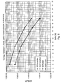
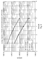
- Figure 5 and 6 provide a comparison of results produced by a conventional full simulation of the multi-path fading channel with respect to results produced using the simplified equivalent channel.
- the results are for a "Pedestrian A" channel simulated with a data rate of 12.2 kbps and a motion speed of 3 km/h for Figure 5 and a motion speed of 120 km/h for Figure 6.
- Bit Error Rate (BER usual) and Block Error Rate (BLER usual) results for the usual simulation channel are illustrated with respect to Bit Error Rate (BER simplified) and Block Error Rate results (BER simplified) for the simplified equivalent channel. As can be observed there is a close correspondence between the results.
- Equation (3) formed using the transformation according to an embodiment of the invention is less complex to compute than equation (1), amongst other reasons because there is no double summation. Furthermore, typically as a result of the transformation, a further simplification can be introduced. This is because the later values for ⁇ i (those closer to L ) are typically low and have a small influence on the resulting calculation of the effects of the channel on the received symbol r , than the earlier components closer to zero delay. Therefore, even if it is not an exact result, a good approximation results when considering only the ⁇ i values over a certain pre-determined threshold.
- a further simplification of the simulation of the multi-path channel may be produced, by not including signal simulators generating complex zero mean gaussian having eigen values which are below a pre-determined threshold. Therefore in such embodiments, the number of signal simulators N is determined from the number of eigen values above the pre-determined threshold, each eigen value above the threshold forming the pre-determined variance for a corresponding signal simulator.
- FIG. 7 An example of this further simplification is provided in table 1 shown in Figure 7.
- the first column labelled "before” the average attenuation with respect to delay for a "Typical Urban” channel adopted by the 3GPP is shown.
- the variance of the signal simulators used in the simplified equivalent channel is shown after transformation at the corresponding delays.
- Figure 8 provides a graphical representation of the values shown in the table of Figure 7. As can be seen from Figures 7 and 8, the number of signal components simulated can be halved using the simplified equivalent channel model, by ignoring the signal components which have a variance ⁇ i which is less than 20dB and therefore do not contribute significantly to the simulation results.
- X represents the first path and Y the second one instead of X 0 and X 1 in the rest of the document.
- the subscripts are used for the time scale (symbol k is written s k ).
- X' and Y' are used instead of Y 0 and Y 1 in the rest of the document.
- the usual channel definition gives ( ⁇ 1 , 0) for the first path and ( ⁇ 2 , ⁇ ) for the second one.
- the correlation coefficient ⁇ 12 between the two paths is derived from ⁇ and the characteristics of the pulse shaping filter.
- ⁇ ' k
- 2 where X' k and Y' k are two independent zero-mean Gaussian processes with variance ⁇ 1 and ⁇ 2 .
- a Markov channel model can represent a radio communications channel using a plurality of channel states representing the states of the radio communications channel.
- a transition between states is determined according to transition probabilities. It is the transition probabilities, which are determined from the effects of the radio communications channel represented, for example, by the signal processing apparatus illustrated in Figure 4.
- An explanation of a process for generating the transition probabilities from the results of a simulated channel is provided in more detail in a technical article by A. Saadani, and P. Tortelier, entitled “A First Order Markov Chain Based Model for Flat Fading Channel,” published at the International Symposium on Personal, Indoor and Mobile Radio Communications, PIMRC'2002.
- a flow diagram presenting in Figure 9 summarises a process of modelling the effects of a radio communications channel.
- channel sounding is performed to identify a number of paths L via which a signal may be received from the radio communications channel.
- the channel sounding process also determines at step S2 an average attenuation and a pre-determined delay with respect to a first of the paths of a communicated radio signal for each of the paths.
- the steps S1 and S2 which characterise the radio communications channel, are performed separately to the channel modelling and simplification of the channel model according to embodiments of the present invention.
- these steps are omitted or have already been performed for channels for which the characterising parameters of the number of paths L , the delay and the average attenuation have already been established, and so may be omitted.
- This is represented in Figure 9 by a dashed line between steps S2 and S4.
- steps S8 and S10 are connected by a dashed line. Accordingly, in some embodiments only steps S10, S12 and S14 are performed in order to represent the effects of the radio communications channel being modelled.
Landscapes
- Physics & Mathematics (AREA)
- Spectroscopy & Molecular Physics (AREA)
- Electromagnetism (AREA)
- Engineering & Computer Science (AREA)
- Computer Networks & Wireless Communication (AREA)
- Signal Processing (AREA)
- Mobile Radio Communication Systems (AREA)
Abstract
Description
- The present invention relates to signal processing apparatus and methods for representing the effects of radio communications channels.
- Data is communicated using radio signals by modulating a radio frequency signal with the data in some way. The radio frequency signal propagates from a transmitting antenna and is detected by a receiving antenna. An estimation of the communicated data is then recovered by de-modulating the received radio signal.
- In order to develop techniques for communicating data using radio frequency signals, models which represent the effects on the data during communication from the transmitter to the receiver antenna have been developed. For example, for mobile radio telephone systems, propagation and channel modelling studies have been performed for radio frequency bands utilised by the Global System for Mobiles (GSM) and the Universal Mobile Telecommunications System (UMTS) for 3rd Generation mobile (3G). To develop such models channel sounding measurements were made and in combination with theoretical considerations, statistical channel models were developed.
- Radio communications channels associated with mobile radio systems such as GSM and UMTS are characterised by including a number of multi-path rays with distinct propagation delays. Each path represents the propagation of a version of a radio signal from a transmitter to a receiver. It is known that the amplitude of each version of the radio signal received via each of the paths can be represented as zero mean complex gaussian random variable. At the receiver the multi-path versions combine to form a composite signal. If the difference between the respective delays for each path exceeds a symbol period of the communicated data, then inter-symbol interference occurs, which must be corrected in order for data to be communicated. Hence, receiver techniques are arranged to recover data in the presence of multi-path propagation. In order to simulate a multi-path radio communications channel, a complex gaussian random variable is generated for each path and for each sample of the simulated radio signal. Therefore, the simulation of such multi-path channels can represent a substantial computational task, requiring a relatively long time to generate simulation results representing the performance of a radio communications receiver. In particular, but not exclusively, a time taken to simulate spread spectrum communications can be prohibitively long. This is because a spread spectrum signal is formed by arranging for the data to be communicated to modulate a spreading code. The spreading code includes a much greater number of bits, referred to as chips, than the data being communicated. Thus for each chip a multi-path fading channel must be simulated, representing a greater computational task than that for simulating a base band data symbol, where no spreading is modelled. For this reason it is desirable to reduce the number of computations by simplifying the simulation of a radio communications channel.
- Examples of communications techniques, which might be simulated, include channel coding techniques such as forward error correction encoding and decoding. In order to evaluate such techniques for a radio communications channel it is desirable to represent the time correlation effects of the radio communications channels. This is because radio communications channels are characterised by fading effects, where multiple rays of the radio signal combine destructively during some instances and constructively at other instants, which can have an effect of introducing bursts of errors of the communicated data. Therefore the performance of the radio channel is time correlated.
- A technical article by Stefan A. Fechtel entitled "A Novel Approach to Modeling and Efficient Simulation of Frequency-Selective Fading Radio Channels," published in the IEEE Journal on Selected Areas in Communications, Vol. 11, No. 3, April 1993, discloses a two step channel orthogonalisation technique. The orthogonalisation technique only provides a facility for obtaining a bounded performance for channel coding techniques, whereas a more exact performance representing the time correlation effects of the radio channel is preferable.
- According to the present invention there is provided a signal processing apparatus operable to represent the effects on a received signal of a radio communications channel having L paths. Each path has an average attenuation and a pre-determined respective delay. The received signal includes a combination of correlated components determined from an effect of pulse shaping filters on the received signal, each correlated component having a correlation coefficient representing a correlation of the received signal component with respect to each of the other components. The signal processing apparatus comprises a plurality of signal simulators, each simulator generating a signal component value proportional to a complex zero mean gaussian random variable having a pre-determined variance. The signal processing apparatus includes a summer operable to sum the signal component values produced from each signal simulator, to form a representation of the signal received via the radio communications channel. The variance of each of the signal simulators is pre-determined by calculating the eigen values of a matrix formed from the correlation coefficients and from a channel correlation matrix which includes the average attenuation of each of the L paths.
- Embodiments of the present invention can provide simulators for radio communications channels, which can represent the radio communications channel with a substantially reduced complexity with respect to known simulators. The reduction in complexity is achieved by performing a transformation of a conventional representation of a radio communications channel having L paths and L correlation coefficients. As a result of the transformation the radio communications channel may not only be simulated with substantially reduced complexity but also removes a requirement for representing the correlation between correlated components from which the received signal is formed. Furthermore in some embodiments, the number of signal simulators may be less than the number of paths L of the radio communications channel being simulated. This is because after the transformation has been performed, the effect of the signal simulators with longer delays is relatively small compared with signal simulators with shorter delays and so ignoring these terms can provide a good approximation to the simulated channel. Therefore in such embodiments, the number of signal simulators is determined from the number of eigen values above a pre-determined threshold, each eigen value above the threshold forming the pre-determined variance for a corresponding signal simulator.
- In some embodiments, the correlation coefficients, representing a correlation between each correlated component with respect to each of the other components, may represent a correlation between the output of each correlator of a rake receiver. For Code Division Muliple Access (CDMA) communications a rake receiver is often used to recover data from a spread spectrum signal. Each correlator of the rake receiver correlates the received signal with respect to a spreading code at a pre-determined delay. The output of each rake correlator may be correlated with respect to the outputs of the other correlators, the correlation being represented by the correlation coefficients. However, embodiments of the present invention are not limited to simulating CDMA communications. In other embodiments the separate components of the communicated signal may be formed Multiple Inputs Multiple Outputs (MIMO) communications or Time Division Multiple Access (TDMA).
- Various further aspects and features of the present invention are defined in the appended claims and include a method of representing the effects of a radio communications channel, a method of simulating a radio communications channel and a computer program.
- Embodiments of the present invention will now be described by way of example only with reference to the accompanying drawings, where like parts are provided with corresponding reference numerals, and in which:
- Figure 1 is a schematic block diagram of a transmitter and receiver chain of parts which are typically involved in simulating data communications via a radio communications channel;
- Figure 2 is a schematic block diagram of a multi-path correlation receiver otherwise known as a rake receiver;
- Figure 3 is a schematic block diagram of the transmitter and receiver chain of Figure 1 adapted to include a simplification of parts representing the radio communications channel;
- Figure 4 is a schematic block diagram of a signal processing apparatus which simulates the parts of the communications channel illustrated in Figure 3;
- Figure 5 provides a graphical representation of simulation results for a "Pedestrian A" radio communications channel with a mobile motion speed of 3km/h, for the simplified equivalent channel and the conventional fully simulated channel;
- Figure 6 provides a graphical representation of simulation results for a "Pedestrian A" radio communications channel with a mobile motion speed of 120km/h, for the simplified equivalent channel and the conventional fully simulated channel;
- Figure 7 is a tabular representation of the components making up a 3GPP "Typical Urban" channel, before and after transformation; and
- Figure 8 provides a graphical representation of multi-path channel components before and after transformation according to the simplification;
- Figure 9 is a flow diagram illustrating the operations involved in simulating the communications channel illustrated in Figures 3 and 4.
-
- Schematic block diagrams in Figures 1, 2 and 3 provide an illustration of a transformation providing a simplification of a simulated radio communications channel according to an embodiment of the present invention. In Figure 1 a data source 1 generates data in digital form, which is fed to an encoder 2. The encoder 2 could apply any form of coding to the data generated from the source 1, such as error correction encoding. A spread spectrum encoder 3 then receives the encoded data, and generates a spread spectrum signal by modulating a spreading code with the encoded data. Typically, the spreading code is formed from a pseudo-random bit sequence having a non-repetitive period of one thousand or more bits, each bit of the modulated spreading code being known as a chip. The spread spectrum signal is then received by a modulator 4. The modulator modulates a base band carrier signal with the chips of the spread spectrum signal. Typically this might include some form of phase or amplitude modulation such a QPSK or QAM in which the phase and/or amplitude of the base band carrier signal is modulated with the encoded data.
- The signal from the modulator 4 is fed to a pulse shaping filter 6 which provides a bandwidth limiting effect which would be applied to the radio signal to be communicated before transmission. As those acquainted with Nyquist bandwidth filtering will appreciate, the pulse-shaping filter is typically in the form of a root raised cosine response so that by employing a corresponding root raised cosine filter at the receiver, an overall raised cosine response is produced. Accordingly by sampling the received data at the symbol time (which for a spread spectrum signal is the chip period), the effects of adjacent chips will be substantially zero at the sampling instant, thereby minimising inter-symbol interference which otherwise might be introduced by the band limiting filters.
- For an equivalent transmitter to that represented in Figure 1, the base band modulated signal would be up converted to a radio frequency signal, amplified and transmitted from an appropriate antenna. However, as those acquainted with the simulation of digital communications systems will appreciate, the effects of the radio communications channel can be modelled by applying equivalent effects to the base band signal produced by the modulator 4.
- Many radio communications channels can be represented as a plurality of L discrete paths, each path providing an independently fading version of the radio signal being represented by a zero mean complex gaussian process also known as a Rayleigh fading process.. Therefore as shown in Figure 1, the simulated transmitted signal passes from the pulse-shaping transmitter filter 6 to an anti-aliasing receiver filter 8, via an L-path Rayleigh fading channel 10 and a noise generator 12. Whilst the L-path Rayleigh fading channel 10 models the effects of a multi-path radio channel, the effects of noise which is introduced during transmission and is present at the receiver antenna (due to thermal noise) is provided by the noise generator 12. If u is the signal before channel 10, then the signal after the noise generator 12 iswith hi the complex channel coefficient and τi the delay for path i. AWGN stands for Additive White Gausssian Noise.

- After passing through the receiver filter 8, the received signal is fed to a de-modulator 14, which produces an estimate of the spread spectrum encoded data produced by the spread spectrum encoder 3, by performing a reverse mapping of the data from the complex base band signal as was applied to the modulator 4. The received spread spectrum encoded data is then fed to a multi-path correlation receiver 16. As will be explained shortly with reference to Figure 2, the multi-path correlation receiver 16, recovers an estimate of the base band encoded data, by correlating the received demodulated data with a reproduced version of the spreading code which was used to form the transmitted signal by the spread spectrum encoder. The de-spread base band encoded data is then fed to a decoder 18, which forms a reverse of the encoding process to estimate the base band data. The estimation of the base band data may include correcting errors in the estimation of the received data, if the data has been encoded using an error correction code. The estimated base band data is then fed to a sink 20.
- Figure 2 provides a more detailed representation of the multi-path correlation receiver, otherwise known as a rake receiver. The rake receiver 16 includes a plurality of L correlators 30, each of the correlators 30 receives on a first input 32 a version of the spreading code Cn (t) which was used to spread the received data bearing spread spectrum signal in the spread spectrum encoder 3. To a second input 34 of the correlators 30, the received sampled signal is fed from the de-modulator. The samples of the received signal are multiplied by the corresponding samples of the spreading code at the chip rate. The result of being multiplied by the spreading code is summed by summers 36 to form, for each spread spectrum symbol, a de-spread sample, which is summed by a further summer 38. The further summer 38 forms a sample of the base band encoded data which is de-spread and has the effect of substantially reducing the inter symbol interference introduced by the multi-path fading channel.
- The spreading code is reproduced within the rake receiver 16. Each version of the spreading code fed on the respective inputs 32 for each correlator 30 is delayed with respect to the first correlator, by an amount which represents a likely temporal position of one of the paths of the L path channel. Accordingly, the delays of each of the spreading codes which are represented as corresponding shifts of the spreading code sequence, aim to reflect the distribution of energy introduced by the multi-path channel.
- From the representation of the spread spectrum communications channel according to the example of Figure 1, a base band data symbols communicated from the output of the encoder 2, to the output r of the multi-path correlation receiver 18, may be represented by the following equation:

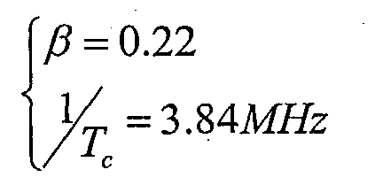
- Each of the L paths of the simulated multi-path channel have parameters (λi,τi ) 0 ≤ i <L, where λ i is the average attenuation of path i with a delay τi. The received symbol r is determined for a transmitted symbol s from equation (1) in which Xi is a complex zero-mean gaussian random variable of variance λ i and ρij is the correlation between the correlators i and j of the rake receiver, the number of correlators in the rake receiver being L. For the example of root raised cosine filters, the correlation coefficients can be derived from the delays through the auto-correlation function of the raised cosine filter, as expressed below:
- As mentioned above, in order to simulate the effects of the multi-path fading channel, the L-path multi-path fading channel 10, requires the generation of a complex gaussian sample per chip of the spread spectrum signal. As will be appreciated, this represents a substantial computational load, in terms of the number of computations per second. Accordingly, a time taken to simulate the communication of a base band symbol including spreading and de-spreading, with multi-path fading channel at the chip rate may be large and for some simulations prohibitive.
- Embodiments of the present invention provide a facility for reducing the number of computations required per second required to simulate a multi-path fading channel. The reduction in complexity according to an embodiment of the invention comprises introducing a transformation of a matrix of values representing the double summation expressed as equation (1) above. The transformation thereby provides a simplification of the channel model.
- The transformation comprises computing the eigen values (µ i ) 0≤i<L of a matrix formed according to the double summation of equation (1), which is └(ρ ij )0≤i, j<L┘K where K is the correlation matrix of the channel (channel correlation matrix). In the usual case of independent paths, it becomes └(ρij )0 ≤i,j<L┘·Diag└(λ i )0 ≤i,j<L┘. According to the simplification provided by the transformation, the schematic block diagram of Figure 1, becomes that shown in Figure 3, where the output of the rake receiver 16' according to the simplified parts shown within a box 50, becomes that expressed by the equation below:

- Where in equation (3), Yi is a complex zero-mean gaussian random variable of variance µ i and there is no correlation component. The main embodiment of the present invention is therefore to replace the channel definition set (λi, τi) by (µi, iTc). For any initial channel model, we find a equivalent one which is adapted to the rate of the transmission we consider. It can be CDMA, TDMA (replacing the chips by symbols) or MIMO. Furthermore, according to equation (3), and as explained below, the number of signal simulators N may be less than or equal to the number of paths L.
- The radio communications channel represented by the schematic block diagram shown in Figure 3, corresponds to that shown in Figure 1 and so only the differences between Figures 1 and 3 will be explained. According to the transformation expressed by equation (3), the multi-path Rayleigh fading channel is transformed, to form an equaivalent channel 10'. As a result of the transformation all parts within the box 50 may be represented by equation (3). A diagram providing an implementation of a signal processing apparatus for representing the parts in box 50 is shown in Figure 4.
- In Figure 4, a plurality of N signal simulators 60 generate signal component values Yi in accordance with zero mean complex random gaussian processes having a variance µ i . The component values are fed to data processors 62 which form the squared magnitude |Y|2 of the signal component values which are fed to a first input 64 of multipliers 66. To a second input 68 the input data signal s is fed. The data signal is scaled by each of the signal component values by the multipliers 66 and fed to a summer 70, which forms the representation of the received signal r. Effectively, the signal component values generated from each of the complex gaussian process form weighting factors for weighting the input data signal.
- Figure 5 and 6 provide a comparison of results produced by a conventional full simulation of the multi-path fading channel with respect to results produced using the simplified equivalent channel. The results are for a "Pedestrian A" channel simulated with a data rate of 12.2 kbps and a motion speed of 3 km/h for Figure 5 and a motion speed of 120 km/h for Figure 6. Bit Error Rate (BER usual) and Block Error Rate (BLER usual) results for the usual simulation channel are illustrated with respect to Bit Error Rate (BER simplified) and Block Error Rate results (BER simplified) for the simplified equivalent channel. As can be observed there is a close correspondence between the results.
- Equation (3) formed using the transformation according to an embodiment of the invention is less complex to compute than equation (1), amongst other reasons because there is no double summation. Furthermore, typically as a result of the transformation, a further simplification can be introduced. This is because the later values for µ i (those closer to L) are typically low and have a small influence on the resulting calculation of the effects of the channel on the received symbol r, than the earlier components closer to zero delay. Therefore, even if it is not an exact result, a good approximation results when considering only the µ i values over a certain pre-determined threshold. As a result, a further simplification of the simulation of the multi-path channel may be produced, by not including signal simulators generating complex zero mean gaussian having eigen values which are below a pre-determined threshold. Therefore in such embodiments, the number of signal simulators N is determined from the number of eigen values above the pre-determined threshold, each eigen value above the threshold forming the pre-determined variance for a corresponding signal simulator.
- An example of this further simplification is provided in table 1 shown in Figure 7. In the first column labelled "before", the average attenuation with respect to delay for a "Typical Urban" channel adopted by the 3GPP is shown. In the second column labelled "after", the variance of the signal simulators used in the simplified equivalent channel is shown after transformation at the corresponding delays. Figure 8 provides a graphical representation of the values shown in the table of Figure 7. As can be seen from Figures 7 and 8, the number of signal components simulated can be halved using the simplified equivalent channel model, by ignoring the signal components which have a variance µi which is less than 20dB and therefore do not contribute significantly to the simulation results.
- For a multi-path channel characterised by three paths, with the following parameters:
- For correlation coefficients describing the reception of a radio signal via the multi-path channel, as follows:Then
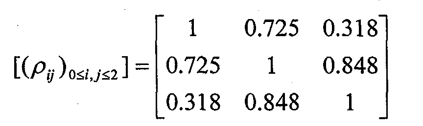

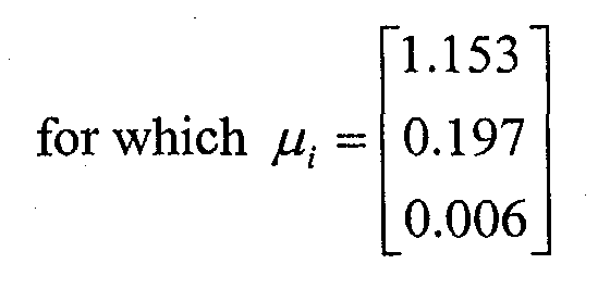
- Perfect channel estimation is assumed and inter-symbol interference is neglected. Some notations are specific to this proof. X represents the first path and Y the second one instead of X0 and X1 in the rest of the document. The subscripts are used for the time scale (symbol k is written sk ). After the transformation, X' and Y' are used instead of Y0 and Y1 in the rest of the document. In the case of two paths, the usual channel definition gives (λ1, 0) for the first path and (λ2, τ) for the second one. The correlation coefficient ρ12 between the two paths is derived from τ and the characteristics of the pulse shaping filter.
- The symbol k at the output of the Rake receiver can be written
- The energy of this symbol is
- We want to prove that the two processes ε and ε' are identical which implies in particular rk = r'k and the equality of the error probabilities after decoding. In order to achieve this, it is enough to prove that the joint densities p(ε) and p(ε') with ε = (ε1 ... εn) and ε' = (ε'1 ... s'n) are equal for all n. The following demonstration assumes n = 2 without loss of generality.
- The characteristic function of the symbol energy can be written

- The same method leads towhere D is the diagonalization of GK so that GK = P*DP.
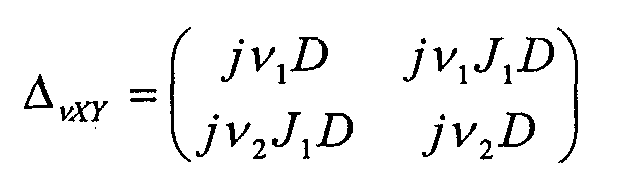
- Furthermore, a simple calculation shows thattherefore

- Finally the two processes are the same. The simplified one obtained with the invention is equivalent to the usual one. So the error probabilities after decoding are the same. It is easy to generalize this proof to the case of more paths. In the case of imperfect channel estimation, a variant of this proof leads to the same result.
- One advantage provided by embodiments of the present invention is that the simplified equivalent channel model can be used to provide a symbol level Markov chain modelling the parts within the box 50 of Figure 3, including spreading, transmission via the communications channel and de-spreading. A Markov channel model can represent a radio communications channel using a plurality of channel states representing the states of the radio communications channel. A transition between states is determined according to transition probabilities. It is the transition probabilities, which are determined from the effects of the radio communications channel represented, for example, by the signal processing apparatus illustrated in Figure 4. An explanation of a process for generating the transition probabilities from the results of a simulated channel is provided in more detail in a technical article by A. Saadani, and P. Tortelier, entitled "A First Order Markov Chain Based Model for Flat Fading Channel," published at the International Symposium on Personal, Indoor and Mobile Radio Communications, PIMRC'2002.
- In summary a flow diagram presenting in Figure 9 summarises a process of modelling the effects of a radio communications channel. Starting with step S1, channel sounding is performed to identify a number of paths L via which a signal may be received from the radio communications channel. The channel sounding process also determines at step S2 an average attenuation and a pre-determined delay with respect to a first of the paths of a communicated radio signal for each of the paths. Generally, the steps S1 and S2, which characterise the radio communications channel, are performed separately to the channel modelling and simplification of the channel model according to embodiments of the present invention. Accordingly, in some embodiments these steps are omitted or have already been performed for channels for which the characterising parameters of the number of paths L, the delay and the average attenuation have already been established, and so may be omitted. This is represented in Figure 9 by a dashed line between steps S2 and S4.
- The steps involved in representing the effects of the radio communications channel are therefore represented in Figure 8 as follows:
- S4: A plurality of correlation coefficients representing a correlation between each of a plurality of components of the received signal are determined in accordance with a communications technique which is used to communicate the received signal. For example, the communications technique may be CDMA, in which the coefficients represent the correlated output of each finger of a rake receiver.
- S6: A matrix is formed from the correlation coefficients and the average attenuation of each of the paths (└(ρ ij )0≤i,j<L ┘·Diag└(λ i )0≤i,j<L ┘).
- S8: For each of the paths of the radio channel, a variance of a complex zero mean gaussian random process is calculated from the eigen values of the formed matrix.
- S10: For each simulated signal component N (where N is less than or equal to the number of paths L), a value from a complex zero mean gaussian random variable having the variance calculated in S8.
- S12: Form the squared magnitude of each of the signal component values calculated in S10.
- S14: The signal component values are summed to produce, for each path, a representation of a signal received via the radio communications channel.
-
- As will be appreciated, once the variances of the zero mean complex gaussian random process have been determined in S8 from the eigen values of the matrix formed in S6, then these steps are no longer necessary when the channel is being simulated. Hence in Figure 9 steps S8 and S10 are connected by a dashed line. Accordingly, in some embodiments only steps S10, S12 and S14 are performed in order to represent the effects of the radio communications channel being modelled.
- Various modifications may be made to the embodiments described above without departing from the scope of the present invention. For example, the present invention finds application in the simulation of receiver diversity and equalisation techniques and can be applied to various communications techniques such as TDMA and MIMO. Various further aspects and features of the present invention are defined in the appended claims.
Claims (18)
- A signal processing apparatus operable to represent the effects on a received signal of a radio communications channel having L paths, each path having an average attenuation and a pre-determined respective delay, wherein the received signal includes a combination of correlated components determined from an effect of pulse shaping filters on the received signal, each correlated component having a correlation coefficient representing a correlation of the received signal component with respect to each of the other components, the signal processing apparatus comprising
a plurality of signal simulators, each simulator generating a signal component value proportional to a complex zero mean gaussian random variable having a pre-determined variance, and
a summer operable to sum the signal component values produced from each signal simulator, to form a representation of the signal received via the radio communications channel, wherein the variance of each of the signal simulators is pre-determined by calculating the eigen values of a matrix formed from the correlation coefficients and from a channel correlation matrix which includes the average attenuation of each of the L paths. - A signal processing apparatus as claimed in Claim 1, wherein the number of signal simulators is less than the number of paths L of the radio communications channel, the number of signal simulators being determined from the number of eigen values above a pre-determined threshold, each eigen value above the threshold forming the pre-determined variance for a corresponding signal simulator.
- A signal processing apparatus as claimed in Claim 1 or 2, wherein the correlated components from which the received signal is formed are representative of components formed from respective correlators of a rake receiver, the received signal being a spread spectrum signal, the correlation coefficients representing a correlation of the output signal of each correlator with respect to the output of the other correlators.
- A signal processing apparatus as claimed in Claim 1, 2 or 3, wherein the signal component value produced by each signal simulator is formed from a squared magnitude of the zero mean complex gaussian random variable.
- A signal processing apparatus as claimed in Claim 4, wherein each of the paths L of the multi-path channel i have parameters (λ i ,τ i )0 ≤ i <L, where λi is the average attenuation of path i having the delay τ i with respect to a first of the paths, and the summer provides a representation of the received signal r for an input signal s represented by the equation:where |Yi |2 is the squared magnitude of the complex zero mean gaussian random variable produced by the i-th signal simulator, the gaussian random variable having the pre-determined variance µ i calculated from the eigen values (µi )0≤ i<L of the matrix formed matrix └(ρij )0≤ i,j<L┘. Diag└(λi )0 ≤i,j<L┘, where ρij are the L correlation coefficients, and Diag└(λi )0 ≤i,j<L┘ is the channel correlation matrix for independent paths.

- A signal processing apparatus as claimed in Claim 5, wherein the correlation coefficients are calculated according to the equation:
- A channel simulator including a signal processing apparatus as claimed in any preceding Claim, and
a noise generator operable to simulate the effects of noise on the received signal. - A channel simulator including a signal processing apparatus as claimed in Claim 7, wherein the noise generator is operable to include the effects of inter symbol interference on the received signal.
- A channel simulator for representing a radio communications channel in accordance with a markov model, the channel simulator comprising a plurality of channel states representing the states of the radio communications channel, a transition between states being determined according to transition probabilities, wherein the transition probabilities are determined from the effects of the radio communications channel represented by the signal processing apparatus according to any of Claims 1 to 6.
- A method of representing the effects of a radio communications channel having L paths on a received signal, each path having an average attenuation and a pre-determined respective delay, wherein the received signal includes a combination of correlated components determined from an effect of pulse shaping filters on the received signal, each correlated component having a correlation coefficient representing a correlation of the received signal component with respect to each of the other components, the method comprising
generating a plurality of complex zero mean gaussian random variables each having a pre-determined variance, and
summing the variables, to form a representation of the signal received via the radio communications channel, wherein the pre-determined variance of each variable is calculated from the eigen values of a matrix formed from the correlation coefficients and from a channel correlation matrix which includes the average attenuation of each of the L paths. - A method of representing as claimed in Claim 10, wherein the number of complex zero mean gaussian random variables is less than the number of paths L of the radio communications channel, the number of variables being determined from the number of eigen values which are above a pre-determined threshold, each eigen value above the threshold forming the variance for a corresponding one of the gaussian random variables.
- A method as claimed in Claim 10 or 11, comprising
forming a squared magnitude of the zero mean complex gaussian variable, before summing to form the representation of the received signal. - A method as claimed in Claim 12, wherein each of the paths L of the multi-path channel i have parameters (λ i ,τ i ) 0 ≤ i <L, where λ i is the average attenuation of path i having a delay τ i with respect to a first of the paths, the summing producing the representation of the received signal r for an input signal s according to the equation:where |Yi|2 is the squared magnitude of the i-th complex zero mean gaussian random variable, the gaussian random variable having the pre-determined variance µi calculated from the eigen values (µ i )0 ≤i<L of the formed matrix └(ρij )0 ≤i,j<M┘·Diag└(λ i )0 ≤i,j<L┘, where ρ ij are the M correlation coefficients, and DiagL└(λ i )0 ≤i,j<L ┘ is the channel correlation matrix for independent paths.

- A method of representing as claimed in Claim 13, wherein the correlation coefficients are calculated according to the equation:
- A method of simulating a radio communications channel, comprising
identifying a number of paths L via which a signal may be received from the radio communications channel,
determining an average attenuation and a pre-determined delay with respect to a first of the paths of a communicated radio signal for each of the paths,
determining a plurality of correlation coefficients from an effect of pulse shaping filters on the received signal,
forming a matrix from the correlation coefficients introduced by the pulse shaping filters and from a channel correlation matrix which includes the average attenuation of each of the L paths,
for each of the paths of the radio channel, calculating a variance of a complex zero mean complex gaussian process from the eigen values of the formed matrix,
generating, for each path, a signal component value proportional to the complex zero mean gaussian random variable having the calculated variance, and
summing the signal component values produced for each path, to form a representation of a signal received via the radio communications channel. - A computer program providing computer executable instructions, which when loaded on to a data processor configures the data processor to operate as a signal processing apparatus as claimed in any of Claims 1 to 6 or a channel simulator as claimed in any of Claims 7 to 9.
- A computer program having computer executable instructions, which when loaded on to a data processor causes the data processor to perform the method according to any of Claims 10 to 15.
- A data carrier having a recording medium on which is recorded instructions representing the computer program claimed in Claim 16 or 17.
Priority Applications (4)
| Application Number | Priority Date | Filing Date | Title |
|---|---|---|---|
| EP03290388A EP1447927A1 (en) | 2003-02-17 | 2003-02-17 | Signal processing apparatus and method |
| US10/780,180 US20040196929A1 (en) | 2003-02-17 | 2004-02-17 | Signal processing apparatus and method |
| JP2004040301A JP2004343695A (en) | 2003-02-17 | 2004-02-17 | Signal processing apparatus, and method of representing effect on radio communication channel |
| CNA2004100052286A CN1527497A (en) | 2003-02-17 | 2004-02-17 | Signal processing apparatus and method |
Applications Claiming Priority (1)
| Application Number | Priority Date | Filing Date | Title |
|---|---|---|---|
| EP03290388A EP1447927A1 (en) | 2003-02-17 | 2003-02-17 | Signal processing apparatus and method |
Publications (1)
| Publication Number | Publication Date |
|---|---|
| EP1447927A1 true EP1447927A1 (en) | 2004-08-18 |
Family
ID=32669048
Family Applications (1)
| Application Number | Title | Priority Date | Filing Date |
|---|---|---|---|
| EP03290388A Withdrawn EP1447927A1 (en) | 2003-02-17 | 2003-02-17 | Signal processing apparatus and method |
Country Status (4)
| Country | Link |
|---|---|
| US (1) | US20040196929A1 (en) |
| EP (1) | EP1447927A1 (en) |
| JP (1) | JP2004343695A (en) |
| CN (1) | CN1527497A (en) |
Cited By (2)
| Publication number | Priority date | Publication date | Assignee | Title |
|---|---|---|---|---|
| AT501645A1 (en) * | 2004-09-06 | 2006-10-15 | Arc Seibersdorf Res Gmbh | CHANNEL SIMULATION AND DEVELOPMENT PLATFORM AND USE THEREOF |
| EP1858180A1 (en) * | 2006-05-19 | 2007-11-21 | Rohde & Schwarz GmbH & Co. KG | System and method for testing and simulating channels in a MIMO mobile radio system |
Families Citing this family (5)
| Publication number | Priority date | Publication date | Assignee | Title |
|---|---|---|---|---|
| GB2449935A (en) * | 2007-06-08 | 2008-12-10 | Fujitsu Ltd | Closed loop MIMO communication system using SISO r.m.s. delay spread to estimate eigen coherence bandwidth. |
| US8737944B2 (en) | 2010-05-21 | 2014-05-27 | Kathrein-Werke Kg | Uplink calibration system without the need for a pilot signal |
| CN102271025B (en) * | 2011-07-25 | 2014-02-26 | 上海华为技术有限公司 | A method and device for reconstructing data |
| US10459117B2 (en) * | 2013-06-03 | 2019-10-29 | Exxonmobil Upstream Research Company | Extended subspace method for cross-talk mitigation in multi-parameter inversion |
| CN109639344B (en) * | 2019-01-02 | 2021-07-06 | 兰州理工大学 | Approximation method for bit error rate of optical MIMO system with PPM modulation under joint effect |
Family Cites Families (11)
| Publication number | Priority date | Publication date | Assignee | Title |
|---|---|---|---|---|
| US5768307A (en) * | 1996-09-13 | 1998-06-16 | Telefonaktiebolaget Lm Ericsson | Coherent demodulation with decision-directed channel estimation for digital communication |
| US5852630A (en) * | 1997-07-17 | 1998-12-22 | Globespan Semiconductor, Inc. | Method and apparatus for a RADSL transceiver warm start activation procedure with precoding |
| US6686879B2 (en) * | 1998-02-12 | 2004-02-03 | Genghiscomm, Llc | Method and apparatus for transmitting and receiving signals having a carrier interferometry architecture |
| FR2782585B1 (en) * | 1998-08-20 | 2000-09-22 | France Telecom | ITERATIVE BOAT RECEIVER AND CORRESPONDING RECEPTION METHOD |
| US6563812B1 (en) * | 1999-10-12 | 2003-05-13 | Mitsubishi Electric Research Laboratories, Inc. | Method and apparatus for detecting multiple signals in a CDMA network |
| US6434366B1 (en) * | 2000-05-31 | 2002-08-13 | Motorola, Inc. | Method and system for estimating adaptive array weights used to transmit a signal to a receiver in a wireless communication system |
| US7158558B2 (en) * | 2001-04-26 | 2007-01-02 | Interuniversitair Microelektronica Centrum (Imec) | Wideband multiple access telecommunication method and apparatus |
| US7103090B2 (en) * | 2001-08-13 | 2006-09-05 | Mediatek Inc. | Timing estimation of direct sequence spread spectrum communications systems over frequency-selective, slowly fading channels |
| US20030054845A1 (en) * | 2001-08-30 | 2003-03-20 | Leonid Krasny | Enhanced time of arrival estimation using reduced complexity optimal processing |
| US6760388B2 (en) * | 2001-12-07 | 2004-07-06 | Qualcomm Incorporated | Time-domain transmit and receive processing with channel eigen-mode decomposition for MIMO systems |
| US7197084B2 (en) * | 2002-03-27 | 2007-03-27 | Qualcomm Incorporated | Precoding for a multipath channel in a MIMO system |
-
2003
- 2003-02-17 EP EP03290388A patent/EP1447927A1/en not_active Withdrawn
-
2004
- 2004-02-17 US US10/780,180 patent/US20040196929A1/en not_active Abandoned
- 2004-02-17 CN CNA2004100052286A patent/CN1527497A/en not_active Withdrawn
- 2004-02-17 JP JP2004040301A patent/JP2004343695A/en not_active Abandoned
Non-Patent Citations (3)
| Title |
|---|
| FECHTEL S A: "A NOVEL APPROACH TO MODELING AND EFFICIENT SIMULATION OF FREQUENCY-SELECTIVE FADING RADIO CHANNELS", IEEE JOURNAL ON SELECTED AREAS IN COMMUNICATIONS, IEEE INC. NEW YORK, US, vol. 11, no. 3, 1 April 1993 (1993-04-01), pages 422 - 431, XP000377964, ISSN: 0733-8716 * |
| KIM H ET AL: "ENHANCED CORRELATED SHADOWING GENERATION IN CHANNEL SIMULATION", IEEE COMMUNICATIONS LETTERS, IEEE SERVICE CENTER, PISCATAWAY,US, US, vol. 6, no. 7, July 2002 (2002-07-01), pages 279 - 281, XP001123680, ISSN: 1089-7798 * |
| SAADANI A ET AL: "A first order Markov chain based model for flat fading channel", FRANCE TELECOM R&D, vol. 4, 15 September 2002 (2002-09-15), pages 1636 - 1639, XP010611543 * |
Cited By (3)
| Publication number | Priority date | Publication date | Assignee | Title |
|---|---|---|---|---|
| AT501645A1 (en) * | 2004-09-06 | 2006-10-15 | Arc Seibersdorf Res Gmbh | CHANNEL SIMULATION AND DEVELOPMENT PLATFORM AND USE THEREOF |
| AT501645B1 (en) * | 2004-09-06 | 2007-11-15 | Arc Seibersdorf Res Gmbh | CHANNEL SIMULATION AND DEVELOPMENT PLATFORM AND USE THEREOF |
| EP1858180A1 (en) * | 2006-05-19 | 2007-11-21 | Rohde & Schwarz GmbH & Co. KG | System and method for testing and simulating channels in a MIMO mobile radio system |
Also Published As
| Publication number | Publication date |
|---|---|
| US20040196929A1 (en) | 2004-10-07 |
| CN1527497A (en) | 2004-09-08 |
| JP2004343695A (en) | 2004-12-02 |
Similar Documents
| Publication | Publication Date | Title |
|---|---|---|
| EP0944977B1 (en) | Method and apparatus for digital symbol detection using transmission medium response estimates | |
| EP0970569B1 (en) | Self-synchronizing equalization techniques and systems | |
| US5233628A (en) | Computer-based bit error simulation for digital wireless communications | |
| EP1792412B1 (en) | Method and apparatus for suppressing communication signal interference | |
| KR101004101B1 (en) | IEEE 802.15.4 Asynchronous Detection Apparatus and Method for LUN-JPAN GPPS Receiver | |
| US7167529B2 (en) | Method and device for radio signal reception | |
| US20040171398A1 (en) | Channel estimation method for a mobile communication system | |
| US20080130674A1 (en) | Method and System For Multi-User Channel Estimation in Ds-Cdma Systems | |
| US20090076789A1 (en) | Method for pre-verifying software/hardware design of communication system | |
| EP1447927A1 (en) | Signal processing apparatus and method | |
| CN101467380B (en) | Method and apparatus for estimating noise variation | |
| US8259854B2 (en) | Channel estimation using common and dedicated pilots | |
| CN108965179A (en) | Enhance two cadence bias estimations of the telemetering comprehensive network system under multipath channel | |
| US7577190B2 (en) | Method for prediction of a channel coefficient | |
| HK1066933A (en) | Signal processing apparatus and method | |
| CA2516946A1 (en) | Reduced complexity sliding window based equalizer | |
| CN103597752B (en) | Method and apparatus for signal equalization using compensation for scrambling code correlation | |
| CN114189414B (en) | A multi-user high-efficiency anti-jamming CDSK chaotic communication system and method | |
| CN110492956A (en) | A kind of error compensation multi-user test method and device for MUSA system | |
| US6925110B2 (en) | Signal processing method and device for a spread spectrum radio communication receiver | |
| CN113747467A (en) | Design method of synchronous and asynchronous NOMA system of nonlinear waveform | |
| CN106357383A (en) | DC-DCSK secret communication system and analysis processing method | |
| Das et al. | Hardware design issues for a mobile unit for next-generation CDMA systems | |
| Kim et al. | Performance analysis of a land mobile satellite system using importance sampling | |
| KR101074566B1 (en) | Performance Analysis Method of Chirp Spread Spectrum System in Multipath Channel Environment |
Legal Events
| Date | Code | Title | Description |
|---|---|---|---|
| PUAI | Public reference made under article 153(3) epc to a published international application that has entered the european phase |
Free format text: ORIGINAL CODE: 0009012 |
|
| AK | Designated contracting states |
Kind code of ref document: A1 Designated state(s): AT BE BG CH CY CZ DE DK EE ES FI FR GB GR HU IE IT LI LU MC NL PT SE SI SK TR |
|
| AX | Request for extension of the european patent |
Extension state: AL LT LV MK RO |
|
| RAP1 | Party data changed (applicant data changed or rights of an application transferred) |
Owner name: FRANCE TELECOM |
|
| REG | Reference to a national code |
Ref country code: HK Ref legal event code: DE Ref document number: 1066933 Country of ref document: HK |
|
| 17P | Request for examination filed |
Effective date: 20050210 |
|
| AKX | Designation fees paid |
Designated state(s): AT BE BG CH CY CZ DE DK EE ES FI FR GB GR HU IE IT LI LU MC NL PT SE SI SK TR |
|
| STAA | Information on the status of an ep patent application or granted ep patent |
Free format text: STATUS: THE APPLICATION HAS BEEN WITHDRAWN |
|
| 18W | Application withdrawn |
Effective date: 20071221 |
|
| REG | Reference to a national code |
Ref country code: HK Ref legal event code: WD Ref document number: 1066933 Country of ref document: HK |