TECHNICAL FIELD
The present invention relates to a method for
producing a permanent magnet and also relates to a press
machine. More particularly, the present invention relates
to a permanent magnet producing method and press machine
that can be used effectively to make an anisotropic bonded
magnet.
BACKGROUND ART
An R-Fe-B based rare-earth magnet (where R is one of
the rare-earth elements including Y, Fe is iron, and B is
boron) is a typical high-performance permanent magnet, has
a structure including, as a main phase, an R2Fe14B phase,
which is a tertiary tetragonal compound, and exhibits
excellent magnet performance.
Such R-Fe-B based rare-earth magnets are roughly
classifiable into sintered magnets and bonded magnets. A
sintered magnet is produced by compacting a fine powder of
an R-Fe-B based magnet alloy (with a mean particle size of
several µm) with a press machine and then sintering the
resultant compact. On the other hand, a bonded magnet is
usually produced by compacting a mixture (i.e., a compound)
of a powder of an R-Fe-B based magnet alloy (with particle
sizes of about 100 µm) and a binder resin within a press
machine.
The sintered magnet is made of a powder with
relatively small particle sizes, and therefore, the
respective powder particles thereof exhibit magnetic
anisotropy. For that reason, an aligning magnetic field is
applied to the powder being compacted by the press machine,
thereby obtaining a compact in which the powder particles
are aligned with the direction of the magnetic field.
In the bonded magnet on the other hand, the powder
particles used have particle sizes exceeding the single
domain critical size, and normally exhibit no magnetic
anisotropy and cannot be aligned under a magnetic field
applied. Accordingly, to produce an anisotropic bonded
magnet in which the powder particles are aligned with
particular directions, a technique of making a magnetic
powder, of which the respective powder particles exhibit
the magnetic anisotropy, needs to be established.
To make a rare-earth alloy powder for an anisotropic
bonded magnet, an HDDR (hydrogenation-disproportionation-desorption-recombination)
process is currently carried out.
The "HDDR" process means a process in which the
hydrogenation, disproportionation, desorption and
recombination are carried out in this order. In this HDDR
process, an ingot or a powder of an R-Fe-B based alloy is
maintained at a temperature of 500 °C to 1,000 °C within an
H2 gas atmosphere or a mixture of an H2 gas and an inert gas
so as to occlude hydrogen. Thereafter, the hydrogenated
ingot or powder is subjected to a desorption process at a
temperature of 500 °C to 1, 000 °C until a vacuum atmosphere
with an H2 partial pressure of 13 Pa or less or an inert
atmosphere with an H2 partial pressure of 13 Pa or less is
created. Then, the desorbed ingot or powder is cooled,
thereby obtaining an alloy magnet powder.
An R-Fe-B based alloy powder, produced by such an HDDR
process, exhibits huge coercivity and has magnetic
anisotropy. The alloy powder has such properties because
the metal structure thereof substantially becomes an
aggregation of crystals with very small sizes of 0.1 µm to
1 µm. More specifically, the high coercivity is achieved
because the grain sizes of the very small crystals,
obtained by the HDDR process, are close to the single
domain critical size of a tetragonal R2Fe14B based compound.
The aggregation of those very small crystals of the
tetragonal R2Fe14B based compound will be referred to herein
as a "recrystallized texture". Methods of making an R-Fe-B
based alloy powder having the recrystallized texture by the
HDDR process are disclosed in Japanese Patent Gazettes for
Opposition Nos. 6-82575 and 7-68561, for example.
However, if an anisotropic bonded magnet is produced
with a magnetic powder prepared by the HDDR process (which
will be referred to herein as an "HDDR powder"), then the
following problems will arise.
A compact, obtained by pressing a mixture (i.e., a
compound) of the HDDR powder and a binder resin under an
aligning magnetic field, has been strongly magnetized by
the aligning magnetic field. If the compact remains
magnetized, however, a magnet powder may be attracted
toward the surface of the compact or the compacts may
attract and contact with each other to be chipped, for
example. In that case, it will be very troublesome to
handle such compacts in subsequent manufacturing process
steps. For that reason, before unloaded from the press
machine, the compact needs to be demagnetized sufficiently.
Accordingly, before the magnetized compact is unloaded from
the press machine, a "degaussing process" of applying a
degaussing field such as a demagnetizing field, of which
the direction is opposite to that of the aligning magnetic
field, or an alternating attenuating field to the compact
needs to be carried out. However, such a degaussing
process normally takes as long a time as several tens of
seconds. Accordingly, in that case, the cycle time of the
pressing process will be twice or more as long as a
situation where no degaussing process is carried out (i.e.,
the cycle time of an isotropic bonded magnet). When the
cycle time becomes that long, the mass productivity will
decrease and the manufacturing cost of the magnet will
increase unintentionally.
As for a sintered magnet on the other hand, even if
the compact thereof is not degaussed sufficiently, the
compact is magnetized just slightly if ever. Also, in the
sintering process step, the magnet powder is exposed to an
elevated temperature that is higher than the Curie
temperature thereof. Thus, the magnet powder will be
completely degaussed before subjected to a magnetizing
process step. In contrast, as for an anisotropic bonded
magnet, if the compact thereof remains magnetized when
unloaded from the press machine, then the magnetization
will remain there until the magnetizing process step. And
if the bonded magnet remains magnetized in the magnetizing
process step, the magnet is very hard to magnetize due to
the hysteresis characteristic of the magnet.
In order to overcome the problems described above, a
main object of the present invention is to provide a
method and a press machine for producing an easily
magnetizable permanent magnet (e.g., an anisotropic bonded
magnet among other things) at a reduced cost by avoiding
various problems caused by the remanence.
Another object of the present invention is to provide
a method for producing an anisotropic bonded magnet and a
press machine, which can fill even a cavity having no
easily feedable shape with a magnet powder just as intended
and thereby can increase the unit weight density of the
compact.
DISCLOSURE OF INVENTION
In order to overcome the problems described above,
preferred embodiments of the present invention provide
An anisotropic bonded magnet producing method
according to the present invention is a method for
producing an anisotropic bonded magnet by feeding a
magnetic powder into a cavity of a press machine and
compacting the magnetic powder. The method includes the
steps of: applying an oscillating magnetic field to a
space including the cavity; moving the magnetic powder
toward the inside of the cavity while aligning the magnetic
powder parallel to the direction of the oscillating
magnetic field; and compacting the magnetic powder inside
of the cavity, thereby obtaining a compact.
In one preferred embodiment, the oscillating magnetic
field is also applied in the step of compacting the
magnetic powder inside of the cavity.
In another preferred embodiment, the oscillating
magnetic field within the cavity has its maximum value
adjusted such that the compact, which has just been
pressed by the press machine, has a surface flux density
of 0.005 tesla or less.
In another preferred embodiment, the maximum value of
the oscillating magnetic field within the cavity is
adjusted to 120 kA/m or less.
In a more preferable embodiment, the maximum value of
the oscillating magnetic field is adjusted to 100 kA/m or
less. In a most preferable embodiment, the maximum value
of the oscillating magnetic field is adjusted to 80 kA/m or
less.
In another preferred embodiment, after the magnetic
powder has been compacted inside of the cavity, the
compact is unloaded from the cavity without being
subjected to any degaussing process.
The oscillating magnetic field may either be an
alternating magnetic field or include a plurality of pulse
magnetic fields.
In another preferred embodiment, the direction of the
oscillating magnetic field within the cavity is
perpendicular to the press direction.
In another preferred embodiment, the direction of the
oscillating magnetic field within the cavity is
substantially horizontal.
In another preferred embodiment, the cavity has an
opening of which the smallest portion has a horizontal
size of 5 mm or less, and the biggest portion of the
cavity has a depth of 10 mm or more.
In another preferred embodiment, at least a portion of
the magnetic powder is an HDDR powder.
In another preferred embodiment, the press machine
includes: a die having a through hole; and a lower punch,
which reciprocates inside of the through hole and with
respect to the die. The step of moving the magnetic powder
toward the inside of the cavity includes the steps of:
positioning a feeder box, including the magnetic powder,
over the through hole of the die after the through hole has
been closed up with the lower punch; and moving the lower
punch downward with respect to the die, thereby defining
the cavity under the feeder box.
A press machine according to the present invention
includes: a die having a through hole; an upper punch and
a lower punch, which are able to reciprocate inside of the
through hole and with respect to the die; and a powder
feeder for feeding a magnetic powder into a cavity that is
defined inside of the through hole of the die. The press
machine further includes an apparatus for applying an
oscillating magnetic field to the magnetic powder being
transported into the cavity.
In one preferred embodiment, the oscillating magnetic
field applying apparatus is able to apply the oscillating
magnetic field to the magnetic powder that has been fed
into the cavity and is being compacted by the upper and
lower punches.
A permanent magnet according to the present invention
is produced by a compaction process. The magnet is
obtained by aligning and compacting a magnetic powder
inside of a press machine under an oscillating magnetic
field. The magnet has a remanence represented by a surface
flux density of 0.005 tesla or less when unloaded from the
press machine without being subjected to any degaussing
process.
An anisotropic bonded magnet according to the present
invention is obtained by binding a magnet powder with a
resin. When a magnetic field of 0 kA/m to 800 kA/m is
applied to the magnet for magnetization purposes, the
ratio ΔB/ΔH of an increase ΔB in magnetic flux to an
increase A H in the strength of the magnetic field is
0.025%/(kA/m) or more.
BRIEF DESCRIPTION OF DRAWINGS
FIGS. 1(a) through 1(f) are cross-sectional views
showing how the main members of a press machine according
to a preferred embodiment of the present invention operate
in respective manufacturing process steps.
FIGS. 2(a) through 2(c) are cross-sectional views
showing how the main members of a press machine according
to another preferred embodiment of the present invention
operate in respective manufacturing process steps.
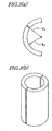
FIG. 3(a) illustrates the shape of a cavity opening,
and FIG. 3(b) illustrates a thin ringlike anisotropic
bonded magnet consisting of a pair of compacts.
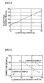
FIG. 4 is a graph showing a relationship between the
current that was supplied to a magnetic field generating
coil to create an alternating magnetic field (i.e.,
alternating current) and the peak magnetic field within the
cavity.
FIG. 5 is a graph showing relationships between the
alternating peak magnetic field and the weight (i.e., unit
weight) of the resultant compact.
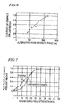
FIG. 6 is a graph showing a relationship between the
magnetic property of a compact per unit weight and the
alternating peak magnetic field.
FIG. 7 is a graph showing relationships between the
flux ratio of a compact per unit weight and the strength of
the magnetizing field.
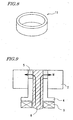
FIG. 8 is a perspective view illustrating a radially
aligned ringlike anisotropic bonded magnet.
FIG. 9 illustrates an exemplary configuration for a
press machine for producing the radially aligned ringlike
anisotropic bonded magnet.
BEST MODE FOR CARRYING OUT THE INVENTION
The present inventors discovered that if an
oscillating magnetic field such as an alternating magnetic
field is applied to a magnetic powder being fed into the
cavity of a press machine, an anisotropic bonded magnet
having a sufficiently high degree of alignment can be
obtained even when its magnetic field strength is smaller
than that of the conventional aligning static magnetic
field by one or more orders of magnitude. The present
inventors obtained the basic idea of the present invention
in this manner.
According to the present invention, the strength of
the magnetic field (i.e., peak magnetic field) to be
applied for alignment purposes can be low enough to reduce
the remanence of the as-pressed compact sufficiently.
Thus, there is no need to perform any additional degaussing
process thereon.
It should be noted that a technique of aligning a
magnetic powder effectively by applying an aligning
magnetic field to the magnetic powder being transported
(i.e., dropped) into a cavity is already described in
Japanese Laid-Open Publications Nos. 2001-93712 and 2001-226701.
In the present invention, however, an anisotropic
bonded magnet compaction process is carried out with a
significantly smaller oscillating magnetic field than that
disclosed in any of these publications, thereby reducing
the surface flux density, resulting from the remanence of
the compact, to 0.005 tesla or less without performing any
degaussing process step. According to the present
invention, no aligning magnetic field generator of a big
size is needed anymore unlike the conventional process and
the cycle time of the pressing process can be shortened
significantly.
Hereinafter, a method for producing an anisotropic
bonded magnet according to a preferred embodiment of the
present invention will be described with reference to the
accompanying drawings.
FIGS. 1(a) through 1(f) show main process steps (i.e.,
from the process step of feeding a powder under an aligning
magnetic field to the process step of compacting the
powder) of a magnet producing method according to the
present invention. The press machine 10 shown in FIG. 1
includes a die 2 having a through hole 1, an upper punch 3
and a lower punch 4, which are able to reciprocate inside
of the through hole 1 and with respect to the die 2, and a
powder feeder (e.g., feeder box) 6 for feeding a magnetic
powder (i.e., a compound) 5 into a cavity that is defined
inside of the through hole 1 of the die 2. The press
machine 10 further includes an oscillating magnetic field
applying apparatus (not shown) for applying a weak
oscillating magnetic field H (i.e., an alternating magnetic
field of which the peak magnetic field is preferably 120
kA/m or less, more preferably 100 kA/m or less and most
preferably 80 kA/m or less) to the magnetic powder 5 being
transported into the cavity.
Hereinafter, a method for producing an anisotropic
bonded magnet with the machine shown in FIG. 1 will be
described.
First, a mixture (i.e., a compound) 5 of the HDDR
powder described above and a binder (i.e., a binder resin)
is prepared and then loaded into a feeder box 6 as shown in
FIG. 1(a). Thereafter, as shown in FIG. 1(b), the feeder
box 6 is transported to over the die 2 of the press machine
10. More specifically, the feeder box 6 is positioned just
over a portion of the die 2 where a cavity will be defined.
In this preferred embodiment, the upper surface of the die
2 is leveled with that of a lower punch 4 and no cavity
space has been created yet at this time.
Next, as shown in FIGS. 1(c) and 1(d), the lower punch
4 is lowered with respect to the die 2 with an oscillating
magnetic field H having alternating magnetic field
directions (i.e., an alternating magnetic field) applied
thereto. As the lower punch 4 falls, a cavity is created
and grows under the feeder box 6. The compound 5 in the
feeder box 6 is absorbed and loaded into the cavity that
increases its size as the lower punch 4 falls.
While the cavity is being filled with the powder in
this manner, the powder particles, included in the compound
5, are effectively aligned under the alternating magnetic
field. This is believed to be because the respective
powder particles being transported into the cavity can
rotate relatively easily due to their decreased fill
density.
The application of an alternating magnetic field as
adopted in the present invention can contribute even more
effectively to the alignment of the powder particles being
loaded than the application of a static magnetic field.
That is to say, if the static magnetic field is applied,
the powder particles will be cross-linked together between
the inner wall surfaces of the cavity to block the cavity
partially. As a result, the powder cannot be loaded
uniformly. On the other hand, if the alternating magnetic
field is applied, then the magnetic field strength will
become zero when the magnetic field direction changes.
Accordingly, the magnetic cross-linking state of the powder
particles collapses and the powder can be loaded uniformly
and rapidly.
The alternating magnetic field for use in this
preferred embodiment preferably has a frequency of at least
10 Hz, more preferably 30 Hz or more. The higher the
frequency of the alternating magnetic field to be applied,
the better the magnetic properties tend to be. However, if
the frequency of the alternating magnetic field becomes too
high, then the die of the press machine will generate some
heat due to eddy current and the magnetic properties will
be saturated, too. For that reason, the alternating
magnetic field preferably has a frequency of 60 Hz to 120
Hz.
It should be noted that the cross-linking of the
powder that blocks the cavity can also be broken off by
creating a magnetic field having a certain direction and by
changing the magnetic field strength in pulses instead of
applying the alternating magnetic field. The key to the
present invention is that the strength of the aligning
magnetic field should be intermittently decreased to either
zero or a sufficiently low level so as to break off the
cross-linking of the powder in the cavity by applying the
aligning magnetic field. Accordingly, it is not always
necessary to invert the direction of the magnetic field
alternately.
In applying such an aligning magnetic field that
oscillates in pulses (i.e., a pulse magnetic field), the
lowest level of the magnetic field applied does not have to
be equal to zero but may be low enough to break off the
magnetic cross-linking of the powder particles (e.g., to 8
kA/m or less).
In this manner, according to the present invention, a
compound including the HDDR powder is fed into the cavity
with a magnetic field, which oscillates between a magnetic
field strength exceeding a predetermined level (i.e., the
"ON" level of the aligning magnetic field) and a magnetic
field strength that is lower than the predetermined level
and is low enough to break off the magnetic cross-linking
(i.e., the "OFF" level of the aligning magnetic field),
applied thereto. Thus, even a cavity having such a shape
as not to be feedable easily by a conventional method can
also be filled with the compound smoothly and uniformly.
As a result, the unit weight of the compact can be
increased.
Next, after the feeder box 6 has been brought back
from over the cavity to a retreated position as shown in
FIG. 1(e), the upper punch 3 is lowered as shown in FIG.
1(f), thereby compressing the compound 5 in the cavity and
obtaining a compact 7.
According to the present invention, a sufficiently
high degree of alignment is achieved even with a weak
magnetic field. Thus, the magnitude (i.e., the maximum
value) of the aligning magnetic field can be reduced
significantly compared with a conventional one.
Accordingly, the magnetization of the compact that has just
been compressed under the aligning magnetic field (i.e.,
the remanence) can be reduced by at least one order of
magnitude as compared with the conventional one. Thus,
various operations that have been required in the
conventional process step of aligning the loaded powder
under a strong magnetic field (e.g., once creating a very
small space over the powder in the cavity to get the powder
aligned more easily, aligning the powder in such a state,
and immediately pressing and compressing the powder to
obtain a compact) are not needed anymore. In addition, the
compact 7 does not have to be subjected to any degaussing
process, either. As a result, according to the present
invention, the cycle time of the pressing process can be
shortened to approximately equal to that of an isotropic
magnet (i.e., half or less of that of the conventional
anisotropic bonded magnet).
It should be noted that while the compound 5 is being
compressed by the upper and lower punches 3 and 4, the
aligning magnetic field may also be applied thereto. The
aligning magnetic field may be applied even during the
compressing process step to maintain appropriate alignment
because the alignment might be disturbed in the compressing
process step. The magnetic field to be applied in the
compressing process step may have a strength that is equal
to or lower than the magnetic field strength in the feeding
process step. This is because this magnetic field is
applied just to eliminate the disturbance of the alignment.
For that reason, the aligning magnetic field to be applied
in the compressing process step does not have to be the
oscillating magnetic field, either. Thus, the oscillating
magnetic field may be applied in the feeding process step
and a static magnetic field may be applied in the
compressing process step. However, to simplify the process,
the oscillating magnetic field that has been applied for
the feeding process step is preferably continuously applied
in the compressing process step, too. This is because if
the oscillating magnetic field is applied continuously,
there is no need to finely synchronize the operation
timings of respective portions of the press machine with
the application timings of the magnetic fields.
In the preferred embodiment described above, the
feeder box 6 is transported to over a region where the
cavity will be defined, and then the cavity space is
created. However, the present invention is in no way
limited to such a feeding method. Alternatively, as shown
in FIGS. 2(a) through 2(c), the feeder box 6 may be
transported to over the cavity that has already been
created such that the compound 5 may be dropped from the
feeder box 6 into the cavity. In that case, before the
feeder box 6 is positioned over the cavity, the aligning
magnetic field (i.e., oscillating magnetic field) starts
being applied to the space including the cavity. Then, the
compound 5 dropping down from the feeder box 6 into the
cavity can be aligned appropriately with the small
oscillating magnetic field.
In the preferred embodiments of the present invention
described above, the oscillating magnetic field is applied
horizontally, i.e., perpendicularly to the pressing
direction (i.e., uniaxial compressing direction). Thus,
the powder particles, filling the cavity, are aligned
horizontally and laterally. Due to magnetic interactions,
the powder particles are chained together horizontally and
laterally. Powder particles, which are located on the upper
surface of the loaded powder, are also chained together
horizontally. As a result, the powder can be easily stored
in the cavity completely without overflowing from the
cavity.
It should be noted that the center axis of the cavity
of the press machine may define a tilt angle with respect
to the perpendicular direction. Also, the direction of the
aligning magnetic field may also define some tilt angle
with respect to the horizontal direction. These
arrangements are appropriately determined depending on
exactly in what shape the bonded magnet should be formed.
Also, according to the present invention, a radially
aligned ringlike anisotropic bonded magnet 11 such as that
shown in FIG. 8 can be obtained. Such a radially aligned
ringlike anisotropic bonded magnet 11 may be made with a
press machine having the configuration shown in FIG. 9, for
example.
In the press machine shown in FIG. 9, a through hole
is provided at the center of a die 2 made of a
ferromagnetic material. A cylindrical core 8, which is
also made of a ferromagnetic material, is inserted into the
center of the through hole. The cavity is defined between
the inner wall of the die through hole and the outer
surface of the core 8. The bottom of the cavity is defined
by the upper surface of a lower punch 4 made of a nonmagnetic
material.
In the press machine shown in FIG. 9, an exciting coil
9 is provided around the lower portion of the core 8 so as
to apply an oscillating magnetic field. By supplying an
alternating current to the exciting coil 9, for example, a
radially aligning magnetic field may be generated within
the cavity as an oscillating magnetic field with a
predetermined strength. If the cavity is loaded with the
compound in such a state, the desired alignment can be
achieved.
In the example illustrated in FIG. 9, the exciting
coil 9 is provided around the core 8. However, the present
invention is in no way limited to this specific preferred
embodiment. Alternatively, an upper core (not shown) may
be provided over the core 8 and another exciting coil may
be provided around the upper core.
The present inventors discovered and confirmed via
experiments that the arrangement including the upper and
lower cores and upper and lower exciting coils could
slightly improve the magnetic properties of the compact as
compared with the arrangement including just one pair of
core and exciting coil. However, when such a press machine
including the exciting coil around the upper core is used,
the work efficiency decreases due to the attraction of the
powder particles to the upper core and the construction of
the press machine gets complicated, too. For that reason,
the arrangement shown in FIG. 9, in which the exciting coil
is provided only around the lower core, is preferred.
Examples
Hereinafter, specific examples of the present
invention will be described.
First, in this specific example, an HDDR powder of an
Nd-Fe-B based rare-earth alloy, including 27.5 wt% of Nd,
1.07 wt% of B, 14.7 wt% of Co, 0.2 wt% of Cu, 0.3 wt% of
Ga, 0.15 wt% of Zr and Fe as the balance, was prepared.
Specifically, first, a rare-earth alloy material having
such a composition was thermally treated at 1,130 °C for 15
hours within an Ar atmosphere and then collapsed and sieved
by a hydrogen occlusion process. Thereafter, the resultant
powder was subjected to an HDDR process, thereby obtaining
an HDDR powder having magnetic anisotropy. The mean
particle size of the powder (as measured by laser
diffraction analysis) was about 120 µm.
The HDDR powder was mixed with a binder (binder resin)
of bisphenol A epoxy resin, which was heated to 60 degrees,
using a biaxial kneader, thereby making an HDDR compound.
The binder was about 2.5 wt% of the overall mixture.
This HDDR compound was compressed and compacted by
using a press machine such as that shown in FIG. 1 under an
alternating magnetic field at 60 Hz. The opening of the
die cavity of the press machine (i.e., on the upper surface
of the die) had an arched shape (i.e., a cross-sectional
shape of the cavity as taken perpendicularly to the
pressing direction) as shown in FIG. 3(a). The dimensions
of the cavity included an outside radius R1 of 19.7 mm, an
inside radius R2 of 16 mm and a depth of 30.65 mm. The
compound was loaded into the cavity so as to have a powder
height (i.e., a fill depth) of 30.65 mm. The dimensions of
a compact resulting from such a cavity included an outside
radius of 19.7 mm, an inside radius of 16 mm and a height
of 19 mm. By combining resultant two compacts together as
shown in FIG. 3(b), an almost radially aligned thin
ringlike anisotropic bonded magnet can be obtained.
FIG. 4 shows a relationship between the current that
was supplied to the magnetic field generating coil of the
press machine to create the alternating magnetic field
(i.e., alternating current) and the peak magnetic field at
the center of the cavity. As can be seen from FIG. 4, the
peak value of the alternating magnetic field, created
within the cavity, increases linearly as the amount of
alternating current to be supplied to the magnetic field
generating coil increases. Accordingly, by adjusting the
amount of the alternating current to be supplied to the
coil, the peak value of the alternating magnetic field
applied to the powder can be controlled. It should be
noted that the magnetic field strength as the ordinate of
the graph is represented in Oe (oersted). A magnetic field
strength according to the SI system of units is obtained by
multiplying this value by 103/(4π). Since 103/(4π) is
approximately equal to 80, 200 Oe is about 16 kA/m
according to the SI system of units.
The direction of the alternating magnetic field,
created within the cavity, was perpendicular to the
pressing direction (i.e., the direction in which the upper
and lower punches went up and down). According to the
graph shown in FIG. 4, even when the alternating current
supplied was 0 A (amperes), a magnetic field was still
generated within the cavity. This is because the
ferromagnetic members, making up the die that was used in
the experiments, were weakly magnetized. If such remanence
is present in the die members in this manner, then the
center of the amplitude of the alternating magnetic field
generated by the coil shifts from the zero level. Even so,
no serious problems will arise. Rather, such remanence is
preferably present because an alternating peak magnetic
field required for alignment purposes can also be obtained
even if a small amount of power is supplied to the magnetic
field generating coil.
FIG. 5 shows relationships between the alternating
peak magnetic field and the weight (i.e., unit weight) of
the resultant compact. As can be seen from FIG. 5, the
higher the alternating peak magnetic field, the lower the
unit weight of the compact. As the powder can be loaded
more smoothly, the unit weight increases. For that reason,
it is believed that if the alternating peak magnetic field
is increased excessively, then it becomes difficult to load
the powder as intended. Also, when the alternating
magnetic field is applied, the die and other members of the
press machine will generate heat. Accordingly, if the
alternating peak magnetic field is intensified
unnecessarily, then the die needs to be cooled in view of
productivity and quality of the magnet. The magnitude of
the alternating peak magnetic field is preferably
determined according to the desired shape and dimensions of
the compact to be obtained, the magnetic properties and
alignment direction (e.g., radial alignment or
perpendicular alignment) of the magnetic powder, and so on.
If the alternating peak magnetic field is intensified
excessively, then the compact that has been just pressed by
the press machine will also have an increased surface flux
density (remanence). As a result, the original objects of
the present invention cannot be achieved anymore. In
addition, the powder cannot be loaded smoothly and the die
will generate heat as described above. In view of these
considerations, the alternating peak magnetic field
preferably has a strength of at most 120 kA/m
(approximately 1,500 Oe), more preferably 100 kA/m
(approximately 1,260 Oe) or less, and even more preferably
80 kA/m (approximately 1,000 Oe) or less. Or the magnetic
field strength may also be 50 kA/m (approximately 630 Oe)
or less.
As is clear from FIG. 6 (to be described later), the
bonded magnet to be obtained in this specific example can
achieve desired magnetic properties in the vicinity of 300
Oe (approximately 24 kA/m). Accordingly, a magnet having a
predetermined unit weight can be obtained at such a
magnetic field strength as not to interfere with powder
loading. More specifically, if the alternating peak
magnetic field is 450 Oe (approximately 36 kA/m) or less, a
sufficient compact unit weight is achievable. The
alternating peak magnetic field preferably falls within the
range of 24 kA/m to 36 kA/m, more preferably within the
range of 24 kA/m to 32 kA/m.
For reference purposes, the graph of FIG. 5 also shows
how compact unit weights changed in comparative examples
Nos. 1 and 2 in which the powder was aligned with a
relatively weak "static magnetic field" applied thereto.
In comparative example No. 1, the static magnetic field had
a strength of 60 Oe during the feeding and compacting,
process steps. In comparative example No. 2 on the other
hand, the static magnetic field had a strength of 150 Oe.
Comparing these comparative examples Nos. 1 and 2 with the
specific example of the present invention, it can be seen
that at the same magnetic field strength, the greater
compact unit weight is achieved by applying the alternating
magnetic field rather than by applying the static magnetic
field. Furthermore, the specific example of the present
invention resulted in a smaller unit weight variation from
one pressing process to another than the comparative
examples. These results show that the powder can be fed
more smoothly by applying the alternating magnetic field
rather than by applying the static magnetic field.
Consequently, the present invention can be used
particularly effectively in a situation where an
anisotropic bonded magnet needs to be obtained using a
cavity that is not easy to feed with the powder (e.g., a
cavity having an aspect ratio (the ratio of the depth to
the smallest size of the opening) of 1 or more).
FIG. 6 shows a relationship between the magnetic
property of the compact per unit weight and the alternating
peak magnetic field. In FIG. 6, the ordinate represents
the ratio of the flux (density) of the specific example of
the present invention to that of comparative example No. 3
(i.e., a compact that was aligned by applying a strong
static magnetic field of 10 kOe thereto). As can be seen
from FIG. 6, when the alternating peak magnetic field
exceeded 300 Oe, the flux of the specific example reached a
level almost equal to that of comparative example No. 3 and
was substantially saturated.
Next, as for a specific example that was obtained at
an alternating peak magnetic field of 420 Oe (approximately
33.6 kA/m), the surface flux density (i.e., remanence) of
the as-press compact (that had not been subjected to any
degaussing process yet) measured 10 gauss (=0.001 tesla) or
less. To omit the degaussing process on a compact, the
remanence of the as-pressed compact is preferably reduced
to 50 gauss (=0.005 tesla) or less. In this specific
example, the strength of the aligning magnetic field is
sufficiently lower than the conventional one. Accordingly,
just a magnetization of less than 50 gauss remains in the
compact that has been aligned under the magnetic field and
no degaussing process is needed anymore. It should be
noted that the anisotropic bonded magnet obtained in this
manner was magnetizable very well.
In contrast, in the prior art in which the powder that
had been fed was compressed and compacted with a strong
static magnetic field (of about 10 kOe, for example)
applied thereto (i.e., in comparative example No. 3), the
remanence of the compact reached as much as 2,000 gauss
(0.2 tesla) and the degaussing process was indispensable.
FIG. 7 is a graph showing relationships between the
flux ratio of a compact per unit weight and the strength of
the magnetizing field (i.e., magnetizing characteristic
curves) for a specific example of the present invention and
a comparative example. In this graph, the solid circles
represent the data points of the specific example of the
present invention while the crosses × represent the data
points of the comparative example. The specific example of
the present invention was a sample that was subjected to
powder feeding and compacting process steps with an
alternating magnetic field having a peak of 400 Oe applied
thereto but that was not subjected to any degaussing
process. On the other hand, the comparative example was a
sample that was compacted with a static magnetic field of
12 kOe applied thereto as an aligning magnetic field and
then subjected to a degaussing process with an alternating
magnetic field applied thereto.
As can be seen from the magnetizing characteristic
curves shown in FIG. 7, in the range where the magnetizing
field strength is 0 kOe to 10 kOe, the ratio (ΔB/ΔH) of
the increase in flux density (ΔB) to the increase in
magnetizing field strength (ΔH) was greater in the specific
example of the present invention than in the comparative
example. More specifically, supposing the flux density at
a magnetizing field strength of 40 Oe is 100%, the ΔB/ΔH
ratio of the specific example in the field strength range
of 0 kOe to 10 kOe was 2%/kOe, which shows that the
specific example was magnetizable much more easily than the
comparative example. It should be noted that 10 kOe is
equivalent to approximately 800 kA/m and 2%/kOe is
equivalent to approximately 0.025%/(kA/m). Thus, according
to the present invention, a ΔB/ΔH ratio of at least
0.025%/(kA/m) is achieved with a magnetic field of 0 kA/m
to 800 kA/m.
In the specific example described above, an
anisotropic bonded magnet is produced with an HDDR powder.
However, the present invention is in no way limited to such
a specific example. Rather, any other type of powder may
also be used as long as the powder exhibits magnetic
anisotropy. Alternatively, a bonded magnet may also be
made of a mixture of the HDDR powder and another
anisotropic powder.
Furthermore, the die cavity of the press machine does
not have to have the shape adopted in the specific example
described above, either, but may have any other arbitrary
shape. It should be noted, however, that the present
invention achieves particularly significant effects on a
cavity, which is normally hard to feed with the powder
(e.g., a shape having an opening with the smallest
horizontal size of 5 mm or less and the greatest depth of
10 mm or more).
Next, a radially aligned ringlike anisotropic magnet
such as that shown in FIG. 8 was produced with a press
machine having the configuration shown in FIG. 9. The
resultant magnet had an outside diameter of 25 mm, an
inside diameter of 23 mm, and a height of 4.8 mm. An HDDR
compound that had the same composition and prepared by the
same method as that described above was used as the
magnetic powder.
The magnetic properties (i.e., flux densities per unit
weight) of the compact and the surface flux densities
(i.e., remanences) of the as-press compact (that was
subjected to no degaussing process) were measured with the
alternating peak magnetic fields of 80 kA/m (approximately
1,000 Oe), 40 kA/m (approximately 500 Oe) and 24 kA/m
(approximately 300 Oe) applied thereto.
As a result, the difference in magnetic property
according to the magnitude of the alternating peak magnetic
field was as small as about 0.5%. Each compact had a
remanence of 0.0007 tesla (7 gauss) or less. Particularly
at an alternating peak magnetic field of 24 kA/m, the
present inventors confirmed that the remanence was 0.0005
tesla (5 gauss) or less, no degaussing process was needed
and the compact was magnetizable very well.
INDUSTRIAL APPLICABILITY
According to the present invention, an oscillating
magnetic field is applied to the powder being fed. Thus,
the magnetic powder can be aligned with the direction of
the aligning magnetic field while being loaded into the
cavity smoothly. For that reason, even though the magnetic
field being applied has a low strength, a sufficient degree
of magnetic field alignment is achieved when the powder has
been loaded. As a result, according to the present
invention, the magnetization, remaining in the as-pressed
compact, can be reduced significantly, and therefore, no
degaussing process is required anymore. Consequently,
according to the present invention, while various problems
resulting from the remanence are avoided, the cycle time of
the pressing process can be shortened and an anisotropic
bonded magnet with excellent properties can be produced at
a low cost.
In addition, according to the present invention, an
oscillating magnetic field is applied as an aligning
magnetic field to the powder being fed. Accordingly, even
a cavity having no easily feedable shape can also be filled
with the magnetic powder just as intended, and the
variation in the unit weight of the compact can be reduced.
Consequently, even a small anisotropic bonded magnet of a
complex shape can be produced with a good yield.