EP1447730A2 - Logical flicker suppression for a temperature controlled heater load - Google Patents
Logical flicker suppression for a temperature controlled heater load Download PDFInfo
- Publication number
- EP1447730A2 EP1447730A2 EP04075311A EP04075311A EP1447730A2 EP 1447730 A2 EP1447730 A2 EP 1447730A2 EP 04075311 A EP04075311 A EP 04075311A EP 04075311 A EP04075311 A EP 04075311A EP 1447730 A2 EP1447730 A2 EP 1447730A2
- Authority
- EP
- European Patent Office
- Prior art keywords
- power
- electrical
- electrical resistance
- drum
- supplied
- Prior art date
- Legal status (The legal status is an assumption and is not a legal conclusion. Google has not performed a legal analysis and makes no representation as to the accuracy of the status listed.)
- Withdrawn
Links
Images



Classifications
-
- H—ELECTRICITY
- H05—ELECTRIC TECHNIQUES NOT OTHERWISE PROVIDED FOR
- H05B—ELECTRIC HEATING; ELECTRIC LIGHT SOURCES NOT OTHERWISE PROVIDED FOR; CIRCUIT ARRANGEMENTS FOR ELECTRIC LIGHT SOURCES, IN GENERAL
- H05B1/00—Details of electric heating devices
- H05B1/02—Automatic switching arrangements specially adapted to apparatus ; Control of heating devices
- H05B1/0227—Applications
- H05B1/023—Industrial applications
- H05B1/0241—For photocopiers
-
- G—PHYSICS
- G05—CONTROLLING; REGULATING
- G05D—SYSTEMS FOR CONTROLLING OR REGULATING NON-ELECTRIC VARIABLES
- G05D23/00—Control of temperature
- G05D23/19—Control of temperature characterised by the use of electric means
- G05D23/1951—Control of temperature characterised by the use of electric means with control of the working time of a temperature controlling device
Definitions
- This invention relates in general to apparatus for controlling temperature and, more particularly, to apparatus for controlling the temperature of a temperature controlled heater to reduce flicker.
- Photothermography is an established imaging technology.
- a photosensitive media is exposed to radiation to create a latent image which can be thermally processed to develop the latent image.
- Devices and methods for implementing this thermal development process are generally known and include contacting the imaged photosensitive media with a heated platen, drum or belt, blowing heated air onto the media, immersing the media in a heated inert liquid and exposing the media to radiant energy of a wavelength to which the media is not photosensitive, e.g., infrared.
- the use of heated drums is particularly common.
- a common photosensitive media usable in these imaging processes is known as a photothermographic media, such as film and paper.
- a photothermographic media such as film and paper.
- One photothermographic media has a binder, silver halide, organic salt of silver (or other reducible, light-insensitive silver source), and a reducing agent for the silver ion.
- these photothermographic media are known as dry silver media, including dry silver film.
- the closeness of the proximity which the photothermographic media is held to the drum partially determines the temperature at which the emulsion in the photothermographic media is heated. Further, the presence of foreign particles between the drum and the photothermographic media can interrupt the flow of heat from the drum to the photothermographic media which can affect image quality.
- the temperature of the drum depends upon many factors. These include the rate at which heat is delivered to the drum, the thermal conductivity and the thermal mass of the drum, the thermal mass of the photothermographic media, the rate, i.e., the number of sheets (if sheet photothermographic media is used) of photothermographic media being processed, the ambient temperature, whether thermal processing is just beginning or whether the thermal processing is in the middle of a long run.
- heated drums are used extensively in various other material processing applications. Examples include calendaring, laminating, coating and drying.
- heat is delivered to such drums through the use of electrical resistance heating elements. Since the heated drum is rotating during thermal processing and since it is a desirable to deliver electrical power to the electrical resistance heating elements during rotation of the drum, is desirable to be able to deliver electrical power from a stationary power source, e.g., the standard AC line, to the moving, rotating drum. Electrical power may be delivered to the drum through the use of slip rings coupled to the drum.
- a stationary power source e.g., the standard AC line
- U.S. Patent No. 6,420,685B1 issued July 16, 2002, inventor Tanamachi discloses a control system for reducing flicker in an electrical resistance heater, a bidirectional solid state switching device connected between the source and the electrical resistance heater; and a control circuit for controlling the bidirectional solid state switching device to supply a varying, phase controlled duty cycle of current to the heater which effectively ramps heater power up and down in response to a binary control signal which randomly turns on the switching device.
- a temperature control system for reducing flicker in an electrical resistance heater comprising:
- the invention has the following advantages.
- FIGs. 1 and 2 A portion of a thermal processor utilizing a rotatable electrically heated drum 10 is illustrated in Figs. 1 and 2.
- a thermal processor may be used to process medical diagnostic quality dry silver film.
- Cylindrical drum 10, mounted on frame 11, is rotatable around axis 12.
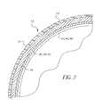
- exterior surface 14 of drum 10 may be coated with silicone layer 15.
- exterior surface 14 of drum 10 is divided into separately controlled heating zones 16, 18, 20. Since the edges of surface 14 of drum 10 may cool more than the central portion of surface 14, a central zone 16 is controlled independently of edge zones 18 and 20.
- Photothermographic media (not shown) is held in close proximity of exterior surface 14 and drum 10 over a portion of the circumference of drum 10 by means of holding down rollers (not shown).
- a known development temperature and dwell time can be achieved.
- a cooling system 22 cools the photothermographic media to a temperature below development temperature. The cooled media is then transported to an output tray.
- cylindrical drum 10 is constructed from aluminum having a diameter, for example, of 8 inches (20.32 centimeters) and with a hollow interior and shell thickness for example, of 0.25 inches (0.635 centimeters).
- electrical resistance heaters 36, 38 and 40 adapted to heat zones 16, 18, 20, respectively.
- Exterior surface 14 of drum 10 may have a very delicate silicone coating 15, so temperature measurement of the drum is done internally in order not to damage the surface coatings.
- temperature sensors (RTDs)42, 44 and 46 adapted to sense the temperature of zones 16, 18 and 20, respectively.
- the temperature of exterior surface 14 is maintained across drum 10 and from sheet to sheet of photothermographic media to within .+ - .0.5 degrees Fahrenheit in order to produce diagnostic quality images.
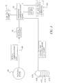
- FIG. 3 A high level block diagram of the major components of the temperature control circuitry is illustrated in Fig. 3. Since drum 10 is rotating, communication to electrical resistance heaters 36, 38 and 40 is done by way of slip ring assembly 67 which is mounted on one end of cylindrical drum 10 and which rotates at the same rate as drum 10. As shown in Fig. 3, circuit board 48 is optically coupled by stationary mounted optical receiver 50 positioned to optically cooperate with rotating circuit board 48. One way communication occurs over optical communications link 66 from the rotating board to the non-rotating processor communication board 52 through optical receiver 50. Rotating circuit board 48 rotates with drum 10 to communicate temperature information from the three drum heated zones 16, 18, 20 to software located on processor communications board 52 via link 66 to optical receiver 50.
- Processor communications board 52 contains a microprocessor whose software interprets the coded temperature information from the three heater zones 16, 18, 20 and converts it to actual zone temperatures. The software then closes the control loop by calculating via a heater control algorithm whether the heater corresponding to the sensed temperature in a particular zone should be turned on or off. The microprocessor then turns on a solid state relay to apply power to the appropriate heater through slip ring assembly 67 A-E.
- FIG. 4 More detail of the function of the processor communication board 52 is shown in Fig. 4.
- 120Vac from source 70 of the imager in which drum 14 is mounted is brought in to the board 52 to power the processor heaters and supply 12Vac to power the rotating board.
- the 12Vac is supplied via step down transformer 100.
- There are three solid state relays 101, 102 and 103 which control power to each of the three drum heaters 36, 38 and 40 under control of microprocessor 104.
- Coded 12 bit digital temperature data is supplied to the microprocessor 104 from each of the three temperature sensors 42, 44, 46 via optical link 66 and optical receiver 50.
- Communication to the rest of the imager is through the 12C interface 105.
- New software can also be downloaded via the communications system.
- Interface 105 also includes an RS232 communications port for service of the processor control system.
- Fig. 5 there is shown in greater detail the electrical components disposed on the rotating drum 10.
- Slip rings 67 A-D supply controlled 120Vac power to resistance heaters 36, 38 and 40. 12Vac power is also supplied via slip ring 67E to bridge rectifier and filter 200 to produce a dc voltage supplied to +5V regulator 202.
- +2.5V precision voltage reference 204 and precision voltage divider chain 206 provide d. c. voltages to Analog to Digital Converter 208 and current sources 210-216.
- Current sources 210, 212 and 214 are respectively coupled to temperature sensors 46, 44, 42.
- the temperature signals from sensors 42, 44, 46 are applied to analog mux 218 which is controlled by rotating microprocessor 220.
- Mux 218 supplies the temperature signals serially to A to D converter 208 which converts them to digital signals which are read and processed by microprocessor 220 and then communicated over optical communications link 66 by microprocessor 220 and infrared LED 222.
- flicker is suppressed by distributing an approximately constant level of power to multiple loads over time.
- flicker suppression solution There are several components to this flicker suppression solution:
- the invention to suppress flicker can be carried out in an exemplary way as follows.
- AC power from source 70 is supplied to electrical resistance heaters 36, 38, 40 to heat zones 16, 18 and 20, respectively by way of solid state relays 101, 102, 103 and slip rings 67A, 67B, 67C.
- Relays 101, 102, 103 are controlled by microprocessor 104 to feed power to electrical resistance heaters 36, 38, 40 at different times within a set period of time.
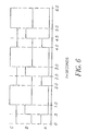
- power supplied to the middle zone 16 heated by heater 38 is twice the power supplied to end zones 18, 20 heated by heaters 36 and 40 respectively, at time 0 seconds.
- X watts of power would be supplied to heater 36 by switching on relay 103.
- relay 103 At time .5 seconds, relay 103 would be switched off, ending power supply to heater 36 and relay 101 would be switched on to supply X watts of power to heater 40. At time 1.0 seconds, relay 101 is switched off and relay 102 switched on to 2 x watts to heater 38. At 2 seconds, power to heater 38 is stopped by switching relay 102 off. The, the process is repeated again during successive 2 second periods. This power cycle is illustrated in Fig. 6 illustrates these signals. Signal A represents the power supplied to heater 36, signal B represents the power supplied to heater 40, and signal C represents the power supplied to heater 38.
- a time period of 2 seconds was used for this example to allow some thermal migration of the applied power to reach the temperature sensing RTDs. This period is dependent on the thermal design of the application, but in practice can vary from 1 to 2 seconds.
- the temperature of a zone is measured at the end of the period, and used to calculate the duty cycle for that zone's next period.
- the duty cycle calculation is that of a Proportional-Integral-Difference (PID) temperature control algorithm.
- PID Proportional-Integral-Difference
- the flicker control discussed reduces the magnitude of this application's peak current load by a factor of 3. In practice, the duty cycles were less then that shown in Fig. 6 which show maximum load conditions. Shorter duty cycles still fall within the flicker control's reduction of the peak load draw of current.
Landscapes
- Physics & Mathematics (AREA)
- General Physics & Mathematics (AREA)
- Engineering & Computer Science (AREA)
- Automation & Control Theory (AREA)
- Control Of Resistance Heating (AREA)
- Photographic Developing Apparatuses (AREA)
- Control Of Temperature (AREA)
Abstract
Description
- Fig. 1 is an isometric view of a portion of a thermal processor utilizing a rotatable, electrically heated drum.
- Fig. 2 is a cross-sectional view of the drum shown in Fig. 1.
- Fig. 3 is a high level block diagram of an electronic temperature control apparatus incorporating the present invention.
- Fig. 4 is a block diagram of a processor communication board utilized in the temperature control apparatus of Fig. 3.
- Fig. 5 is a block diagram of a rotating board utilized in the temperature control apparatus of Fig. 3.
- Fig. 6 is a diagram useful in explaining the present invention. In general, the present invention provides a temperature controlled, electrically heated drum with flicker suppression. A cylindrical drum has a surface and is rotatable on an axis. An electrical heater is thermally coupled to the surface of the cylindrical drum. Solid State Relays (SSRs), non-rotatably mounted in conjunction with the cylindrical drum and electrically coupled to the electrical heaters through slip rings, controls the temperature by controlling the flow of electricity to the electrical heaters in response to control signals from the non-rotatably mounted microprocessor. A temperature sensor mechanism, rotatably mounted in conjunction with the cylindrical drum sense the temperature of the surface of the cylindrical drum and produces temperature signals indicative thereof. A microprocessor, non-rotatably mounted with respect to the cylindrical drum, controls the temperature of the electrically heated drum by generating the control signals in response to the temperature signals. An optical mechanism, coupled to the temperature control means, the temperature sensor means and rotating microprocessor means, optically couples the temperature signals from the rotating temperature sensor means to the non-rotating microprocessor means.
Claims (11)
- A temperature control system for reducing flicker in an electrical resistance heater comprising:an electrical resistance heater divided into at least two electrical loads and;a source of electrical power for repetitively supplying electrical power to each of said at least two electrical loads at successive different time sub periods within a predetermined time period, wherein the sum of the power supplied to said at least two electrical loads is equal to the total power supplied to said electrical resistance heater during said predetermined time period.
- The system of claim 1 wherein the power supplied during each time subperiod is proportional to its fraction of the total power supplied during said predetermined time period.
- The system of claim 1 wherein the power supplied to each electrical load begins at or after power is supplied to each said other electrical load.
- The system of claim 1 wherein the time subperiod during which power is supplied to each electrical load is out of phase with the time subperiod during which power is supplied to each other electrical load.
- The system of claim 1 including logical control means for controlling the supply of power from said source of electrical power to said at least two electrical loads of said electrical resistance heater.
- The system of claim 1 wherein said electrical resistance heater heats a rotating drum which contacts media for processing.
- A temperature controlled electrically heated drum assembly having reduced flicker comprising:a cylindrical drum rotatable on an axis, said drum having an outer surface divided into a plurality of zones arranged longitudinally along said axis of said drum;a plurality of electrical resistance heaters, one for each of said plurality of zones, thermally coupled to each of said plurality of zones, respectively; anda source of electrical power for repetitively supplying electrical power to each of said plurality of electrical resistance heaters at successive different time subperiods within a predetermined time period, wherein the sum of the power supplied to each said plurality of electrical resistance heaters is equal to the total power supplied during said predetermined time period.
- The drum assembly of claim 7 wherein the power supplied during each time subperiod is proportional to its fraction of the total power supplied during said predetermined time period.
- The drum assembly of claim 7 wherein the power supplied to each of said plurality of electrical resistance heaters begins at or after power is supplied to another of said plurality of electrical resistance heaters.
- The drum assembly of claim 7 wherein the time subperiod during which power is supplied to each of said plurality of electrical resistance heaters is out of phase with the time subperiod during which power is supplied to each other of said plurality of electrical resistance heaters.
- The drum assembly of claim 7 including logical control means for controlling the supply of power from said source of electrical power to said plurality of electrical resistance heaters.
Applications Claiming Priority (2)
| Application Number | Priority Date | Filing Date | Title |
|---|---|---|---|
| US365789 | 2003-02-13 | ||
| US10/365,789 US6849833B2 (en) | 2003-02-13 | 2003-02-13 | Logical flicker suppression for a temperature controlled heater load |
Publications (2)
| Publication Number | Publication Date |
|---|---|
| EP1447730A2 true EP1447730A2 (en) | 2004-08-18 |
| EP1447730A3 EP1447730A3 (en) | 2005-03-23 |
Family
ID=32681722
Family Applications (1)
| Application Number | Title | Priority Date | Filing Date |
|---|---|---|---|
| EP04075311A Withdrawn EP1447730A3 (en) | 2003-02-13 | 2004-02-02 | Logical flicker suppression for a temperature controlled heater load |
Country Status (3)
| Country | Link |
|---|---|
| US (1) | US6849833B2 (en) |
| EP (1) | EP1447730A3 (en) |
| JP (1) | JP2004247307A (en) |
Families Citing this family (7)
| Publication number | Priority date | Publication date | Assignee | Title |
|---|---|---|---|---|
| GB2449651A (en) * | 2007-05-29 | 2008-12-03 | Ultra Electronics Ltd | Power control system to reduce imbalances |
| JP5744497B2 (en) * | 2010-12-09 | 2015-07-08 | キヤノン株式会社 | Image forming apparatus |
| US10119727B2 (en) * | 2015-05-06 | 2018-11-06 | Infineon Technologies Ag | Mechanical relay and solid-state relay for controlling heating elements |
| US11454677B2 (en) | 2016-07-01 | 2022-09-27 | Weber-Stephen Products Llc | Wireless control and status monitoring for electric grill with current protection circuitry |
| US10551893B2 (en) * | 2016-07-01 | 2020-02-04 | Weber-Stephen Products Llc | Digital power supply with wireless monitoring and control |
| US10524312B2 (en) | 2016-07-01 | 2019-12-31 | Weber-Stephen Products Llc | Electric grill with current protection circuitry |
| US10537199B2 (en) | 2016-07-01 | 2020-01-21 | Weber-Stephen Products Llc | Digital power supply |
Family Cites Families (10)
| Publication number | Priority date | Publication date | Assignee | Title |
|---|---|---|---|---|
| GB8432542D0 (en) * | 1984-12-21 | 1985-02-06 | Micropore International Ltd | Power control arrangement |
| US4908956A (en) | 1989-03-28 | 1990-03-20 | Impact Systems, Inc. | Power controller for heater load |
| DE9314747U1 (en) * | 1993-09-30 | 1994-02-10 | Rowenta-Werke GmbH, 63071 Offenbach | Electrical circuit arrangement for the flicker standard-compliant and network feedback-free heating power control of heating resistors of electrical household appliances, in particular electrical bread toasters |
| US5580478A (en) | 1994-05-09 | 1996-12-03 | Minnesota Mining And Manufacturing Company | Apparatus for controlling the temperature of and a moveable, electrically heated object using two way on axis optical communication |
| DE69638285D1 (en) * | 1995-06-30 | 2010-12-16 | Canon Kk | image heating |
| JPH10115997A (en) | 1996-10-09 | 1998-05-06 | Canon Inc | Power control device |
| US5818208A (en) | 1996-12-19 | 1998-10-06 | Abb Power T&D Company Inc. | Flicker controllers using voltage source converters |
| JP3847951B2 (en) * | 1997-04-30 | 2006-11-22 | キヤノン株式会社 | Heating control device |
| US6188208B1 (en) | 1999-08-02 | 2001-02-13 | General Electric Company | Cycle-skipping power control for AC line-powered loads |
| US6420685B1 (en) * | 2000-12-20 | 2002-07-16 | Eastman Kodak Company | Control of electrical heater to reduce flicker |
-
2003
- 2003-02-13 US US10/365,789 patent/US6849833B2/en not_active Expired - Lifetime
-
2004
- 2004-02-02 EP EP04075311A patent/EP1447730A3/en not_active Withdrawn
- 2004-02-12 JP JP2004035260A patent/JP2004247307A/en active Pending
Also Published As
| Publication number | Publication date |
|---|---|
| EP1447730A3 (en) | 2005-03-23 |
| JP2004247307A (en) | 2004-09-02 |
| US20040159652A1 (en) | 2004-08-19 |
| US6849833B2 (en) | 2005-02-01 |
Similar Documents
| Publication | Publication Date | Title |
|---|---|---|
| JP2909102B2 (en) | Method and apparatus for fixing a powder image on a receiving support | |
| US9665048B2 (en) | Image forming apparatus having a temperature setting portion to control a target temperature | |
| US20050061792A1 (en) | Heating device and heating method | |
| US6849833B2 (en) | Logical flicker suppression for a temperature controlled heater load | |
| JPH1091017A (en) | Image heating device | |
| US5946526A (en) | Method and device for controlling temperature of heating source of image forming apparatus | |
| US7324771B2 (en) | Method for minimizing temperature droop in a fuser | |
| US7634209B2 (en) | Temperature control method for fixing device, and fixing device and image-forming apparatus that use the same | |
| JP2004280083A (en) | Image heating device | |
| US5666593A (en) | Resistance Temperature Detector (RTD) sensor for a heat and pressure fuser | |
| JP2001100588A (en) | Heating device and image forming device | |
| US6744014B1 (en) | Apparatus for controlling temperature of moveable electrically heated objects/drums | |
| JP2019101251A (en) | Image heating device | |
| US6442366B1 (en) | External radiant heater for fuser members and method of making same | |
| JPH10312133A (en) | Heating device and image forming device | |
| EP1223480A2 (en) | Control of electrical heater to reduce flicker | |
| JP3796350B2 (en) | Heating device and image forming apparatus provided with the heating device | |
| JPH07114294A (en) | Fixing device | |
| JP3507260B2 (en) | Heating device and heating element | |
| JP2003156828A (en) | Segmented heated drum processor | |
| JP2003215974A (en) | Fixing device and image forming apparatus including the same | |
| JPH11338298A (en) | Heating device and image forming apparatus provided with the heating device | |
| JPH05265350A (en) | Fixing device for image forming apparatus | |
| JP2002278350A (en) | Heating device and image forming device | |
| JPH09329991A (en) | Image forming device |
Legal Events
| Date | Code | Title | Description |
|---|---|---|---|
| PUAI | Public reference made under article 153(3) epc to a published international application that has entered the european phase |
Free format text: ORIGINAL CODE: 0009012 |
|
| AK | Designated contracting states |
Kind code of ref document: A2 Designated state(s): AT BE BG CH CY CZ DE DK EE ES FI FR GB GR HU IE IT LI LU MC NL PT RO SE SI SK TR |
|
| AX | Request for extension of the european patent |
Extension state: AL LT LV MK |
|
| PUAL | Search report despatched |
Free format text: ORIGINAL CODE: 0009013 |
|
| AK | Designated contracting states |
Kind code of ref document: A3 Designated state(s): AT BE BG CH CY CZ DE DK EE ES FI FR GB GR HU IE IT LI LU MC NL PT RO SE SI SK TR |
|
| AX | Request for extension of the european patent |
Extension state: AL LT LV MK |
|
| RIC1 | Information provided on ipc code assigned before grant |
Ipc: 7H 05B 1/02 B Ipc: 7G 03G 15/20 B Ipc: 7G 05D 23/20 A |
|
| 17P | Request for examination filed |
Effective date: 20050713 |
|
| AKX | Designation fees paid |
Designated state(s): DE FR GB |
|
| 17Q | First examination report despatched |
Effective date: 20070508 |
|
| RAP1 | Party data changed (applicant data changed or rights of an application transferred) |
Owner name: CARESTREAM HEALTH, INC. |
|
| STAA | Information on the status of an ep patent application or granted ep patent |
Free format text: STATUS: THE APPLICATION IS DEEMED TO BE WITHDRAWN |
|
| 18D | Application deemed to be withdrawn |
Effective date: 20080610 |