EP1447681B1 - System for determining a position of a moving transponder - Google Patents
System for determining a position of a moving transponder Download PDFInfo
- Publication number
- EP1447681B1 EP1447681B1 EP04100176.9A EP04100176A EP1447681B1 EP 1447681 B1 EP1447681 B1 EP 1447681B1 EP 04100176 A EP04100176 A EP 04100176A EP 1447681 B1 EP1447681 B1 EP 1447681B1
- Authority
- EP
- European Patent Office
- Prior art keywords
- signal
- transponder
- magnetic field
- arrangement
- strengths
- Prior art date
- Legal status (The legal status is an assumption and is not a legal conclusion. Google has not performed a legal analysis and makes no representation as to the accuracy of the status listed.)
- Expired - Lifetime
Links
- 230000001788 irregular Effects 0.000 claims description 7
- 230000004044 response Effects 0.000 claims description 2
- 230000007274 generation of a signal involved in cell-cell signaling Effects 0.000 claims 1
- 238000001514 detection method Methods 0.000 description 4
- 238000000034 method Methods 0.000 description 3
- 230000007423 decrease Effects 0.000 description 2
- 230000000694 effects Effects 0.000 description 2
- 230000004913 activation Effects 0.000 description 1
- 230000000386 athletic effect Effects 0.000 description 1
- 230000005540 biological transmission Effects 0.000 description 1
- 230000008859 change Effects 0.000 description 1
- 230000008878 coupling Effects 0.000 description 1
- 238000010168 coupling process Methods 0.000 description 1
- 238000005859 coupling reaction Methods 0.000 description 1
- 238000000605 extraction Methods 0.000 description 1
- 238000012544 monitoring process Methods 0.000 description 1
- 230000000737 periodic effect Effects 0.000 description 1
- 230000008569 process Effects 0.000 description 1
- 230000001105 regulatory effect Effects 0.000 description 1
- 238000005070 sampling Methods 0.000 description 1
- 230000008054 signal transmission Effects 0.000 description 1
- 230000007723 transport mechanism Effects 0.000 description 1
Images


Classifications
-
- G—PHYSICS
- G07—CHECKING-DEVICES
- G07C—TIME OR ATTENDANCE REGISTERS; REGISTERING OR INDICATING THE WORKING OF MACHINES; GENERATING RANDOM NUMBERS; VOTING OR LOTTERY APPARATUS; ARRANGEMENTS, SYSTEMS OR APPARATUS FOR CHECKING NOT PROVIDED FOR ELSEWHERE
- G07C1/00—Registering, indicating or recording the time of events or elapsed time, e.g. time-recorders for work people
- G07C1/22—Registering, indicating or recording the time of events or elapsed time, e.g. time-recorders for work people in connection with sports or games
Definitions
- the invention relates to a system for determining a position of a moving transponder.
- FR 2 619 644 discloses a detection system for detecting the time of cars in a car racing event.
- the cars each have a transponder emitting signals that are received by a receiving unit.
- the transponders receive magnetic field signals form an antenna loop in the track.
- the receiving unit determines the time of passing of the cars by manipulating the received signal, which has a frequency in the range of 2-3 MHz.
- the prior art system is problematic in that the transmitted magnetic signals only have a small bandwidth, since magnetic coupling requires a relatively low carrier frequency. Such a relatively small bandwidth puts restrictions on the number of transponders that can be employed in a sporting event. Moreover limitations exist as to the distance for detection of the signal of the transponder since the power of these magnetically transmitted signals decreases rapidly with the distance to the antenna.
- WO 00/19235 discloses a system having a transmitter emitting radio frequent signals towards RFID tags.
- the system has a detector incorporating circuitry for detecting changes in the range of an RFID tag from the detector and for triggering an alarm if a detected change in range of an RFDI tag exceeds a predetermined threshold or if the RFDI radio tag cannot be detected by the detector.
- the range is detected by measuring the time of a returned radio signal from a tag, by measuring the strength of a returned radio signal from a tag or by detecting changes in a periodic interval at which energy is transmitted by a tag.
- US 5,666,101 discloses an apparatus for real time measuring of parameters and operational times of vehicles running around a racetrack.
- a detecting station is arranged at a location along the racetrack and is set up to both receive and transmit radio frequency signals both from/to a transceiver unit installed on each vehicle.
- the transmission of a signal from the transceiver unit is in response to the transmitting from the detecting station, the station being provided with an electronic radio frequency-converter for transmitting and modulating the received signals over a wide band coaxial cable.
- WO 02/101408 discloses a system and method for monitoring and displaying athlete characteristics.
- the tag device of the athlete may provide information in a modulating signal representative of physiological characteristics of the athlete.
- the character of the further signal itself is no longer relevant for the position determination of the moving transponder.
- the position determination is performed on the basis of received signal strengths, incorporated in the message portion(s) of the further signal.
- the further signal can thus be optimised with respect to e.g. the bandwidth.
- This further signal can e.g. be an electromagnetic signal of.high frequency that has a high bandwidth enabling the use of a large number of transponders in a sporting event.
- the power of an electromagnetic signal decreases less rapidly with the distance travelled, such that the high frequency signal can be received at a further distance from the transponder.
- the signal generating arrangement and the signal receiving arrangement are decoupled from each other.
- a common antenna is usually employed for generation and reception of the signal.
- the distance between the transponder and the signal receiving arrangement can be made larger as explained above. Consequently the signal receiving arrangement can be decoupled from the signal generating arrangement, allowing individual optimisation of both arrangements for their specific tasks.
- a conventional antenna arrangement can e.g. be used as antenna of the signal receiving arrangement.
- the transponder is adapted to insert a further message portion in the further signal that comprises additional data.
- additional data can be accommodated in the further signal as a result of the higher available bandwidth of the further signal.
- additional data may e.g. relate to an identification code of the signal generating arrangement. This may e.g. be advantageous in the case of multiple signal generating arrangements being used along a track in order to e.g. provide information of the specific signal generating arrangement being passed by the transponder.
- the additional data may relate to a variable of and/or.concerning an object associated with the transponder. It can e.g. be envisaged that a variable relating to telemetric data, such as the heart rate of an athlete, is probed by a sensor and transmitted as additional data to the processing unit.
- the invention further relates to a transponder as defined in claim 8.
- the transponder is assigned an identification code and adapted to insert this identification code in a further message portion of the further signal.
- the transponder comprises an encryption module for encrypting the further signal.
- the encryption module may apply an encryption scheme or algorithm suitable for preventing e.g. misuse of the system whereby introducing falsified messages by a device similar to transponders of the invention can suggest a position and thus passing time of transponders in reality not in that position.
- the invention further relates to a transponder signal as defined in claim 12.
- the transponder signal may further comprise message portions relating to an identification code of the signal generating arrangement and/or an identification code of the transponder and/or a variable concerning an object associated with the transponder.
- the transponder signal may be encrypted.
- FIG. 1 With reference to Fig. 1 , there is shown a system 1 for determining a position of a moving transponder 2.
- a system 1 for determining a position of a moving transponder 2 In Fig. 1 three transponders 2 are shown moving in the direction of the arrow 3. However according to the invention a large number of transponders 2 can be employed.
- the system 1 comprises a signal generating arrangement 4 having a signal generator 5 transmitting substantially stationary magnetic field signals 6 via a loop 7.
- a loop 7 is often positioned such that participants carrying the transponders 2 in a sporting event are obliged to pass this loop 7.
- Loop 7 may e.g. be a single wire embedded in or hanging over e.g. a circuit track.
- the frequency of the magnetic field signals 6 is in the order of 100 kHz, e.g. 125 kHz.
- the power of these signals 6 is generally limited by regulatory requirements.
- the power used allows the components of the transponder 2, as shown in Fig. 2 , to be of standard quality.
- the signal generating arrangement 4 may have been assigned an identity code, schematically indicated by 8.
- the system 1 further comprises a signal receiving arrangement 9 having an antenna 10 and a processing unit 11.
- the signal receiving arrangement 9 is adapted to receive and process a further signal 12 transmitted by the transponders 2.
- the signal 6 and the further signal 12 comprise computer readable media for they embody data in a modulated data signal such as a carrier wave or other transport mechanism.
- modulated data signal means a signal that has one or more of its characteristics set or changed in such a manner as to encode information in the signal.
- this form of computer readable media includes wireless media such as acoustic, RF, infrared and other wireless media. Combinations of any of the above should also be included within the scope of computer readable media.
- the further signal 12 preferably is an electromagnetic signal.
- the frequency of the signal 12 is preferably in the range of 0.4-6 GHz, more preferably in the range of 0.4-1.0 GHz, e.g. 433, 868 or 915 MHz.
- the signal generating arrangement 4 and the signal receiving arrangement 9 are separate arrangements. As a result both arrangements 4, 9 can be optimised individually for.their specific tasks.
- the loop 7 may e.g. be of considerable dimensions, e.g. 50 meters in length. Since the loop 7 is no longer used for detection of signals but solely for generation of the magnetic field signal 6 of relatively low frequency, larger loops 7 are allowed since noise and wavelength considerations for receiving signals are no longer relevant.
- system 1 may comprise further signal generating arrangements 4 and/or signal receiving arrangements 9 in communicative connection with individual or shared signal generators 5 and processing units 11 respectively.
- FIG. 2 a more detailed view is provided of several components of the system 1 as shown in Fig. 1 .
- the signal generating arrangement 4 comprises a relatively low frequency signal generator 5 having a signal generator 13 and an amplifier 14. Further an identification code 8 is assigned to the signal generating arrangement 4, such that this identification code 8 may be inserted in the magnetic field signal 6 transmitted via the loop 7.
- the transponder 2 comprises a battery 15 for power supply of a microprocessor 16.
- the transponder 2 further comprises an arrangement 17, such as a pick-up coil, suitable for receiving the magnetic field signal 6 of relatively low frequency of the loop 7.
- the magnetic field signal 6 received by the pick-up coil 17 is fed to an A/D converter 18 to enable processing of the signal 6 by the microprocessor 16.
- the transponder 2 comprises a wake-up unit 19 for activation of the transponder 2 in the neighbourhood of the signal generating arrangement 4.
- the unit 19 may be awoken in accordance with the strength of the signal 6 induced in pick-up coil 17.
- Microprocessor 16 determines the signal strength of the signal 6 which is an indication of the power of the received signal 6 and so a measure for the distance to the loop antenna 7 in the track.
- transponder 2 may have a sensor 20 feeding additional data to the microprocessor 16. These additional data may e.g. relate to telemetric data of an athlete carrying the transponder 2. Further an identity code 21 may have been assigned to the transponder 2. Finally transponder 2 comprises a transmitter 22 and an antenna 23 for transmitting the electromagnetic signal 12 of relatively high frequency.
- the electromagnetic signal 12 comprises message portions 24, 25, 26.
- the microprocessor 16 may insert these message portions 24, 25 and 26 in the electromagnetic signal 12. In Fig. 2 , these message portions 24, 25 and 26 respectively relate to or are indicative of the determined signal strength the identity code 21 of the transponder 2, and the additional data.
- Additional data may e.g. relate to the identity code 8 of the signal generating arrangement 4 and/or the heart rate, obtained by the sensor 20, of a user carrying the transponder 2.
- the complete message or portion thereof may be encrypted by e.g. the microprocessor 16 to prevent e.g. fraudulent use by generating similar signals by a third party.
- the transponder 2 may transmit electromagnetic signals 12 with identical message portions 24 and/or 25 and/or 26 several times during passing of the loop 7.
- one electromagnetic signal 12 may comprise a message portion 24 that comprises several determined signal strengths associated with different times of passing the loop 7.
- the signal receiving arrangement 9 comprises an antenna 10 and a processing unit 11.
- Processing unit 11 comprises a receiver 27 for receiving the electromagnetic signal 12 of the transponder 2.
- the processing unit 11 comprises an optional decryption unit 28 for decrypting the encrypted electromagnetic signals 12.
- the message portions 24, 25 and 26 will be extracted by an extraction unit 29 from the electromagnetic signal 12.
- the extracted message portions 24, 25 and 26 are input to a microprocessor 30 suitable for analysing the message portions 24, 25 and 26. It is noted that the functions of the units 28 and/or 29 may be performed by the microprocessor 30 as well.
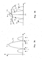
- a signal pattern 31 representing the magnetic signal 6 of relatively low frequency is displayed as generated by the signal generating arrangement 4 and received by the transponder 2 as a function of time. It is noted that time and position are comparable in passing the loop 7.
- the signal pattern 31 is a result of the loop 7. Between the wires of the loop 7, schematically illustrated on the horizontal axis in Fig. 3A , the signal is more pronounced than outside of the loop 7, as indicated by the side lobes of smaller height. Nulls of the signal pattern 31 correspond to the position directly above the wires of the loop 7.
- the transponder 2 determines the received magnetic field strength of the magnetic field signal 6 as described with regard to Fig. 2 , at irregular time intervals as indicated by the arrows on the horizontal axis.
- the amount of samples taken of the magnetic field strength is variable and depends e.g. on the speed of the moving transponder 2 and the way the microprocessor 16 is programmed. Microprocessor 16 may be programmed to sample the received magnetic field strengths at random time intervals. As an example the resulting amount of samples taken ranges typically from 20 for car racing to 200 for an athlete walking for one passing of the loop 7. For the sake of simplicity the amount of samples taken is limited to five in Fig. 3A .
- Fig. 3B two signal patterns are displayed for explanation purposes.
- the electromagnetic signal 12 of high frequency, transmitted by the transponder 2 is indicated by 32. It is clear that from this pattern 32 no time or position for passing the loop 7 can be determined.
- the irregular pattern 32 is mainly a result of multi-path effects.
- message portion 24 comprises an indication of the received signal strength of the magnetic field signal 6, a number of points 33 of the magnetic signal pattern 31 are known at the processing unit 11. From these points 33 a position determination pattern 31', corresponding to the magnetic field signal pattern 31, can be constructed or reconstructed. From this position determination pattern 31', the position on the loop and thus the moment PT of passing of the loop 7 can be analyzed by the microprocessor 29.
- the microprocessor 30 may further analyze further message portions 25, 26 incorporated in electromagnetic signal 12, such as the identity of the transponder 2 (identity code 21), the identity code of the signal generating arrangement 4 from which the magnetic field signal 6 has been received (identity code 8) and/or variables of and/or concerning the object carrying the transponder 2 (by using sensor 20).
- the invention enables e.g. a competitor in a race to wear the transponder 2 on his shirt instead of on his shoe, since the character of the further signal 12 is not essential for the position determination of the competitor.
- the further signal can thus be made suitable for detection on a larger distance, while still being able to be used for position determination by virtue of the incorporated message portion 24 with 'position information'.
- determination of time and/or position can be achieved. This behavior allows for having the loop 7 deeper in a circuit track, which is e.g. advantageous in snowy conditions.
Description
- The invention relates to a system for determining a position of a moving transponder.
- Many areas of sports require determination of position and/or time of the participants, including car racing, athletics and skating. To achieve such a determination the participants carry a transponder being in communicative connection with measuring stations.
-
FR 2 619 644 - The prior art system is problematic in that the transmitted magnetic signals only have a small bandwidth, since magnetic coupling requires a relatively low carrier frequency. Such a relatively small bandwidth puts restrictions on the number of transponders that can be employed in a sporting event. Moreover limitations exist as to the distance for detection of the signal of the transponder since the power of these magnetically transmitted signals decreases rapidly with the distance to the antenna.
- However, employing an electromagnetic transmission method is problematic as well. The unit receiving such electromagnetic signals will often not be able to determine a position of the transponder, since these electromagnetic signals show a highly irregular pattern, mainly as a result of multi-path effects associated with electromagnetic signals of relatively high frequency.
-
WO 00/19235 -
US 5,666,101 discloses an apparatus for real time measuring of parameters and operational times of vehicles running around a racetrack. A detecting station is arranged at a location along the racetrack and is set up to both receive and transmit radio frequency signals both from/to a transceiver unit installed on each vehicle. The transmission of a signal from the transceiver unit is in response to the transmitting from the detecting station, the station being provided with an electronic radio frequency-converter for transmitting and modulating the received signals over a wide band coaxial cable. -
WO 02/101408 - Cenker et al, IEEE COMP. SOC. PRESS, March 1991, page 483-489 ISBN:0-8186-2133-8 discloses iterative algorithms in irregular sampling.
- It is therefore desirable to provide a system employing a high bandwidth while still being able to determine the position and/or passing time of a transponder.
- To this end a system is provided for determining a position of a moving transponder as defined in
claim 1. - By inserting the received signal strength in a message portion of the further signal, the character of the further signal itself is no longer relevant for the position determination of the moving transponder. The position determination is performed on the basis of received signal strengths, incorporated in the message portion(s) of the further signal. As a result, the further signal can thus be optimised with respect to e.g. the bandwidth. This further signal can e.g. be an electromagnetic signal of.high frequency that has a high bandwidth enabling the use of a large number of transponders in a sporting event. Furthermore, the power of an electromagnetic signal decreases less rapidly with the distance travelled, such that the high frequency signal can be received at a further distance from the transponder.
- In a preferred embodiment of the invention, the signal generating arrangement and the signal receiving arrangement are decoupled from each other. In prior art systems a common antenna is usually employed for generation and reception of the signal. By using an electromagnetic signal the distance between the transponder and the signal receiving arrangement can be made larger as explained above. Consequently the signal receiving arrangement can be decoupled from the signal generating arrangement, allowing individual optimisation of both arrangements for their specific tasks. A conventional antenna arrangement can e.g. be used as antenna of the signal receiving arrangement.
- In a further embodiment of the invention, the transponder is adapted to insert a further message portion in the further signal that comprises additional data. Such additional data can be accommodated in the further signal as a result of the higher available bandwidth of the further signal. These additional data may e.g. relate to an identification code of the signal generating arrangement. This may e.g. be advantageous in the case of multiple signal generating arrangements being used along a track in order to e.g. provide information of the specific signal generating arrangement being passed by the transponder. Alternatively, or in addition, the additional data may relate to a variable of and/or.concerning an object associated with the transponder. It can e.g. be envisaged that a variable relating to telemetric data, such as the heart rate of an athlete, is probed by a sensor and transmitted as additional data to the processing unit.
- It is noted that the above embodiments, or aspects thereof, may be combined.
- The invention further relates to a transponder as defined in
claim 8. - In an embodiment of the invention, the transponder is assigned an identification code and adapted to insert this identification code in a further message portion of the further signal. As a result, information is available with regard to the identity of the source of the further signal.
- In an embodiment of the invention, the transponder comprises an encryption module for encrypting the further signal. The encryption module may apply an encryption scheme or algorithm suitable for preventing e.g. misuse of the system whereby introducing falsified messages by a device similar to transponders of the invention can suggest a position and thus passing time of transponders in reality not in that position.
- The invention further relates to a transponder signal as defined in
claim 12. - The transponder signal may further comprise message portions relating to an identification code of the signal generating arrangement and/or an identification code of the transponder and/or a variable concerning an object associated with the transponder. The transponder signal may be encrypted.
- The invention will be further illustrated with reference to the attached drawing, which shows a preferred embodiment according to the invention. It will be understood that the system according to the invention is not in any way restricted to this specific and preferred embodiment.
- In the drawings:
-
Fig. 1 shows a system for determining a position of a moving transponder according to an embodiment of the invention. -
Fig. 2 schematically shows several components of the system as displayed inFig. 1 . -
Figs. 3A and 3B show signal characteristics associated with the system shown inFigs. 1 and2 . - With reference to
Fig. 1 , there is shown asystem 1 for determining a position of a movingtransponder 2. InFig. 1 threetransponders 2 are shown moving in the direction of thearrow 3. However according to the invention a large number oftransponders 2 can be employed. - The
system 1 comprises asignal generating arrangement 4 having asignal generator 5 transmitting substantially stationary magnetic field signals 6 via aloop 7. Such aloop 7 is often positioned such that participants carrying thetransponders 2 in a sporting event are obliged to pass thisloop 7.Loop 7 may e.g. be a single wire embedded in or hanging over e.g. a circuit track. The frequency of the magnetic field signals 6 is in the order of 100 kHz, e.g. 125 kHz. The power of these signals 6 is generally limited by regulatory requirements. The power used allows the components of thetransponder 2, as shown inFig. 2 , to be of standard quality. Thesignal generating arrangement 4 may have been assigned an identity code, schematically indicated by 8. - The
system 1 further comprises asignal receiving arrangement 9 having anantenna 10 and aprocessing unit 11. Thesignal receiving arrangement 9 is adapted to receive and process afurther signal 12 transmitted by thetransponders 2. - As used herein, the signal 6 and the
further signal 12 comprise computer readable media for they embody data in a modulated data signal such as a carrier wave or other transport mechanism. The term "modulated data signal" means a signal that has one or more of its characteristics set or changed in such a manner as to encode information in the signal. By way of example, and not limitation, this form of computer readable media includes wireless media such as acoustic, RF, infrared and other wireless media. Combinations of any of the above should also be included within the scope of computer readable media. In one embodiment, thefurther signal 12 preferably is an electromagnetic signal. The frequency of thesignal 12 is preferably in the range of 0.4-6 GHz, more preferably in the range of 0.4-1.0 GHz, e.g. 433, 868 or 915 MHz. - The
signal generating arrangement 4 and thesignal receiving arrangement 9 are separate arrangements. As a result botharrangements signal generating arrangement 4, theloop 7 may e.g. be of considerable dimensions, e.g. 50 meters in length. Since theloop 7 is no longer used for detection of signals but solely for generation of the magnetic field signal 6 of relatively low frequency,larger loops 7 are allowed since noise and wavelength considerations for receiving signals are no longer relevant. - Note that the
system 1 may comprise furthersignal generating arrangements 4 and/orsignal receiving arrangements 9 in communicative connection with individual or sharedsignal generators 5 andprocessing units 11 respectively. - In
Fig. 2 a more detailed view is provided of several components of thesystem 1 as shown inFig. 1 . - The
signal generating arrangement 4 comprises a relatively lowfrequency signal generator 5 having asignal generator 13 and anamplifier 14. Further anidentification code 8 is assigned to thesignal generating arrangement 4, such that thisidentification code 8 may be inserted in the magnetic field signal 6 transmitted via theloop 7. - The
transponder 2 comprises abattery 15 for power supply of amicroprocessor 16. Thetransponder 2 further comprises anarrangement 17, such as a pick-up coil, suitable for receiving the magnetic field signal 6 of relatively low frequency of theloop 7. The magnetic field signal 6 received by the pick-upcoil 17 is fed to an A/D converter 18 to enable processing of the signal 6 by themicroprocessor 16. Furthermore thetransponder 2 comprises a wake-upunit 19 for activation of thetransponder 2 in the neighbourhood of thesignal generating arrangement 4. Theunit 19 may be awoken in accordance with the strength of the signal 6 induced in pick-upcoil 17.Microprocessor 16 determines the signal strength of the signal 6 which is an indication of the power of the received signal 6 and so a measure for the distance to theloop antenna 7 in the track. This determination may be performed at irregular intervals and subsequently transmitted at the same irregular intervals by thetransponder 2 to thesignal receiving arrangement 9. Moreover thetransponder 2 may have asensor 20 feeding additional data to themicroprocessor 16. These additional data may e.g. relate to telemetric data of an athlete carrying thetransponder 2. Further anidentity code 21 may have been assigned to thetransponder 2. Finallytransponder 2 comprises atransmitter 22 and anantenna 23 for transmitting theelectromagnetic signal 12 of relatively high frequency. Theelectromagnetic signal 12 comprisesmessage portions microprocessor 16 may insert thesemessage portions electromagnetic signal 12. InFig. 2 , thesemessage portions identity code 21 of thetransponder 2, and the additional data. These additional data may e.g. relate to theidentity code 8 of thesignal generating arrangement 4 and/or the heart rate, obtained by thesensor 20, of a user carrying thetransponder 2. The complete message or portion thereof may be encrypted by e.g. themicroprocessor 16 to prevent e.g. fraudulent use by generating similar signals by a third party. - It is noted that the
transponder 2 may transmitelectromagnetic signals 12 withidentical message portions 24 and/or 25 and/or 26 several times during passing of theloop 7. Moreover oneelectromagnetic signal 12 may comprise amessage portion 24 that comprises several determined signal strengths associated with different times of passing theloop 7. - The
signal receiving arrangement 9 comprises anantenna 10 and aprocessing unit 11. Processingunit 11 comprises areceiver 27 for receiving theelectromagnetic signal 12 of thetransponder 2. Moreover theprocessing unit 11 comprises anoptional decryption unit 28 for decrypting the encrypted electromagnetic signals 12. Subsequently themessage portions extraction unit 29 from theelectromagnetic signal 12. The extractedmessage portions microprocessor 30 suitable for analysing themessage portions units 28 and/or 29 may be performed by themicroprocessor 30 as well. - Next, the operation of the
system 1 as displayed inFigs. 1 and2 will be described in view ofFigs. 3A and 3B . - In
Fig. 3A asignal pattern 31 representing the magnetic signal 6 of relatively low frequency is displayed as generated by thesignal generating arrangement 4 and received by thetransponder 2 as a function of time. It is noted that time and position are comparable in passing theloop 7. Thesignal pattern 31 is a result of theloop 7. Between the wires of theloop 7, schematically illustrated on the horizontal axis inFig. 3A , the signal is more pronounced than outside of theloop 7, as indicated by the side lobes of smaller height. Nulls of thesignal pattern 31 correspond to the position directly above the wires of theloop 7. Thetransponder 2 determines the received magnetic field strength of the magnetic field signal 6 as described with regard toFig. 2 , at irregular time intervals as indicated by the arrows on the horizontal axis. The amount of samples taken of the magnetic field strength is variable and depends e.g. on the speed of the movingtransponder 2 and the way themicroprocessor 16 is programmed.Microprocessor 16 may be programmed to sample the received magnetic field strengths at random time intervals. As an example the resulting amount of samples taken ranges typically from 20 for car racing to 200 for an athlete walking for one passing of theloop 7. For the sake of simplicity the amount of samples taken is limited to five inFig. 3A . - In
Fig. 3B two signal patterns are displayed for explanation purposes. Theelectromagnetic signal 12 of high frequency, transmitted by thetransponder 2, is indicated by 32. It is clear that from thispattern 32 no time or position for passing theloop 7 can be determined. Theirregular pattern 32 is mainly a result of multi-path effects. Since in theelectromagnetic signal 12,message portion 24 comprises an indication of the received signal strength of the magnetic field signal 6, a number ofpoints 33 of themagnetic signal pattern 31 are known at theprocessing unit 11. From these points 33 a position determination pattern 31', corresponding to the magneticfield signal pattern 31, can be constructed or reconstructed. From this position determination pattern 31', the position on the loop and thus the moment PT of passing of theloop 7 can be analyzed by themicroprocessor 29. It is noted that in a practical situation the samples may be taken and/or analyzed only near the maximum M of thesignal patterns 31 and 31', since only this part of the pattern 31' is relevant for the determination of the time thetransponder 2 passes theloop 7. Themicroprocessor 30 may further analyzefurther message portions electromagnetic signal 12, such as the identity of the transponder 2 (identity code 21), the identity code of thesignal generating arrangement 4 from which the magnetic field signal 6 has been received (identity code 8) and/or variables of and/or concerning the object carrying the transponder 2 (by using sensor 20). - The invention enables e.g. a competitor in a race to wear the
transponder 2 on his shirt instead of on his shoe, since the character of thefurther signal 12 is not essential for the position determination of the competitor. The further signal can thus be made suitable for detection on a larger distance, while still being able to be used for position determination by virtue of the incorporatedmessage portion 24 with 'position information'. By inserting the received signal strength of the magnetically induced signal 6 in amessage portion 24 of theelectromagnetic signal 12, determination of time and/or position can be achieved. This behavior allows for having theloop 7 deeper in a circuit track, which is e.g. advantageous in snowy conditions.
Claims (14)
- System (1) for determining a passing time when a
moving transponder (2) passes a signal generating arrangement (4), said moving transponder (2) adapted to receive a stationary magnetic field signal (6) and to wirelessly transmit a further signal (12), said system comprising the signal generating arrangement (4), at least one signal receiving arrangement (9), and processing means (11) adapted to determine said passing time, wherein:- the signal generating arrangement (4) is adapted to generate said stationary magnetic field signal (6) for said transponder (2), said transponder being adapted to determine a plurality of signal strengths of said received magnetic field signal and said magnetic field signal having a first frequency;- the signal receiving arrangement (9) is adapted to receive said further signal (12) of said transponder (2), wherein said transponder (2) is adapted to insert the plurality of received signal strengths associated with different times in a message portion (24) of the further signal (12), wherein said further signal is transmitted to the processing means (11) and has a second frequency that is higher than the first frequency;- the processing means (11) are adapted to determine the passing time in accordance with said plurality of said received signal strengths determined by said moving transponder (2);- said signal receiving arrangement (9) is configured to receive said plurality of received signal strengths and said processing means (11) are adapted to construct or reconstruct a position determination pattern on the basis of said plurality of received signal strengths for determining the passing time;- wherein said position determination pattern corresponds to a magnetic field signal pattern representing the stationary magnetic field signal. - System (1) according to claim 1, wherein said further signal (12) is an electromagnetic signal with a carrier frequency in the range of 0.4-6 GHz.
- System (1) according to claim 1, wherein said signal generating arrangement (4) and said signal receiving arrangement (9) are decoupled from each other.
- System (1) according to claim 1, wherein said transponder (2) is adapted to insert a further message portion (25, 26) in said further signal (12) comprising additional data.
- System (1) according to claim 4, wherein said signal generating arrangement (4) is assigned an identification code (8) and adapted to insert said identification code (8) in said magnetic field signal (6), such that said transponder (2) may employ said identification code (8) as said additional data.
- System (1) according to claim 4, wherein said transponder (2) comprises at least one sensor (20) for probing at least one variable of and/or concerning an object associated with said transponder (2), such that said transponder may employ said variable as said additional data.
- System (1) according to claim 1, wherein at least three signal strengths of said plurality of signal strengths are associated with irregular time intervals.
- Transponder (2) for enabling a determination of a passing time when the transponder (2) passes a signal generating arrangement (4), said transponder being adapted for receiving a stationary magnetic field signal (6) from said signal generating arrangement (4) and for wirelessly transmitting a further signal (12), characterized in that said transponder is further adapted for determining a plurality of signal strengths of said received magnetic field signal and to insert the plurality of received signal strengths associated with different times in a message portion (24) of the further signal (12);
wherein said magnetic field signal has a first frequency, and said further signal has a second frequency that is higher than the first frequency;
wherein the further signal having the plurality of signal strengths, when transmitted to a signal receiving arrangement (9), enables a position determination pattern to be constructed or reconstructed by a processing means (11) on the basis of said plurality of received signal strengths, said position determination pattern for determining said time of passing of the signal generating arrangement and said position determination pattern corresponding to a magnetic field signal pattern representing the stationary magnetic field signal. - Transponder (2) according to claim 8, wherein said transponder (2) is assigned an identification code (21) and adapted to insert said identification code (21) in a further message portion (25) of said further signal (12).
- Transponder (2) according to claim 8, wherein said transponder (2) comprises at least one sensor (20) for probing at least one variable of and/or concerning an object associated with said transponder (2) and is adapted to insert said variable in a further message portion (26) of said further signal.
- Transponder (2) according to claim 8, wherein said transponder comprises an encryption module (16) for encrypting said further signal (12).
- Transponder signal (12) for enabling a determination of a passing time when a transponder (2) passes a signal generating arrangement (4), said transponder signal being transmitted wirelessly by the transponder (2) to a signal receiving arrangement (9) in response to reception of a stationary magnetic field signal (6) of the signal generation arrangement (4), characterized in that said transponder signal comprises a message portion (24) indicative of a plurality of signal strengths associated with different times of said received magnetic field signal (6);
wherein said magnetic field signal has a first frequency, and said transponder signal has a second frequency that is higher than the first frequency;
wherein the transponder signal having the plurality of signal strengths, when transmitted to a signal receiving arrangement (9), enables a position determination pattern to be constructed or reconstructed by a processing means (11) on the basis of said plurality of received signal strengths, said position determination pattern for determining said time of passing of the signal generating arrangement and said position determination pattern corresponding to a magnetic field signal pattern representing the stationary magnetic field signal. - Transponder signal (12) according to claim 12,
wherein said transponder signal (12) further comprises message portions (25,26) relating to an identification code (8) of said signal generating arrangement (4) and/or an identification code (21) of said transponder (2) and/or a variable concerning an object associated with said transponder (2). - Transponder signal (12) according to claim 12,
wherein said transponder signal (12) is an encrypted transponder signal.
Applications Claiming Priority (2)
| Application Number | Priority Date | Filing Date | Title |
|---|---|---|---|
| US10/367,121 US6864829B2 (en) | 2003-02-14 | 2003-02-14 | System for determining a position of a moving transponder |
| US367121 | 2003-02-14 |
Publications (4)
| Publication Number | Publication Date |
|---|---|
| EP1447681A2 EP1447681A2 (en) | 2004-08-18 |
| EP1447681A3 EP1447681A3 (en) | 2004-08-25 |
| EP1447681B1 true EP1447681B1 (en) | 2013-10-02 |
| EP1447681B2 EP1447681B2 (en) | 2018-06-06 |
Family
ID=32681748
Family Applications (1)
| Application Number | Title | Priority Date | Filing Date |
|---|---|---|---|
| EP04100176.9A Expired - Lifetime EP1447681B2 (en) | 2003-02-14 | 2004-01-21 | System for determining a position of a moving transponder |
Country Status (3)
| Country | Link |
|---|---|
| US (1) | US6864829B2 (en) |
| EP (1) | EP1447681B2 (en) |
| ES (1) | ES2440653T5 (en) |
Cited By (3)
| Publication number | Priority date | Publication date | Assignee | Title |
|---|---|---|---|---|
| EP3073447A1 (en) | 2015-03-26 | 2016-09-28 | Swiss Timing Ltd. | Method and system for measuring a transit time, and transponder module of the system |
| EP3316226A1 (en) | 2016-10-31 | 2018-05-02 | Harald Mika | Method and system for timekeeping |
| EP3316225A1 (en) | 2016-11-01 | 2018-05-02 | Swiss Timing Ltd. | Transponder module for determining a transit time in a measurement system |
Families Citing this family (14)
| Publication number | Priority date | Publication date | Assignee | Title |
|---|---|---|---|---|
| US20050203651A1 (en) * | 2001-12-03 | 2005-09-15 | Fernando Vincenzini | System and process for charting the time and position of a contestant in a race |
| US7342500B2 (en) * | 2006-03-24 | 2008-03-11 | Mark Iv Industries, Corp. | Compact microstrip transponder antenna |
| US8079925B2 (en) * | 2006-10-12 | 2011-12-20 | Cairos Technologies Ab | Concept for activating a game device |
| US7676268B2 (en) | 2006-11-30 | 2010-03-09 | Medtronic, Inc. | Medical methods and systems incorporating wireless monitoring |
| EP2267632A1 (en) * | 2009-06-12 | 2010-12-29 | Nxp B.V. | User interaction device |
| DE102010060571B3 (en) * | 2010-11-16 | 2011-11-17 | Sportident Gmbh | Method and arrangement for recording pass times at checkpoints, in particular at sports events |
| ES2952400T3 (en) * | 2014-07-28 | 2023-10-31 | Mylaps B V | Transponder module and access module to activate and configure said transponder module |
| EP2981028B1 (en) * | 2014-07-28 | 2020-05-06 | MyLaps B.V. | Transponder module and access module for activating and configuring such transponder module over a CAN bus |
| EP3035298B9 (en) * | 2014-12-19 | 2021-08-18 | MyLaps B.V. | Determining the passing time of a moving transponder |
| DE102015010398A1 (en) * | 2015-08-13 | 2017-03-02 | race result AG | Sports Timing |
| US9592795B1 (en) | 2015-11-02 | 2017-03-14 | James A. Whiteside | Theft deterrence, prevention, and recovery system and method |
| US9643638B1 (en) | 2015-12-16 | 2017-05-09 | Bosch Automotive Service Solutions Inc. | Motorized service cart |
| US10560844B2 (en) | 2017-03-15 | 2020-02-11 | International Business Machines Corporation | Authentication of users for securing remote controlled devices |
| US11594115B2 (en) * | 2020-09-17 | 2023-02-28 | Sensormatic Electronics, LLC | Methods and apparatuses for determining a position of a security tag |
Family Cites Families (13)
| Publication number | Priority date | Publication date | Assignee | Title |
|---|---|---|---|---|
| FR2619644A1 (en) | 1987-08-19 | 1989-02-24 | Braconnier Dominique | Detection device, particularly for timing vehicles in sporting competitions |
| US5666101A (en) * | 1990-12-14 | 1997-09-09 | Cazzani; Umberto | High-efficiency apparatus for measuring operational parameters and times of vehicles running around a racetrack |
| US5294931A (en) | 1992-04-29 | 1994-03-15 | Texas Instruments Deutschland Gmbh | Method of interrogating a plurality of transponders arranged in the transmission range of an interrogating device and transponders for use in the said method |
| US5311185A (en) * | 1992-08-31 | 1994-05-10 | Hochstein Peter A | Supervised personnel monitoring system |
| US5887176A (en) * | 1996-06-28 | 1999-03-23 | Randtec, Inc. | Method and system for remote monitoring and tracking of inventory |
| US5842118A (en) * | 1996-12-18 | 1998-11-24 | Micron Communications, Inc. | Communication system including diversity antenna queuing |
| GB9821046D0 (en) | 1998-09-28 | 1998-11-18 | Whitesmith Howard W | Detection system |
| US6261247B1 (en) | 1998-12-31 | 2001-07-17 | Ball Semiconductor, Inc. | Position sensing system |
| EP1065625A1 (en) | 1999-07-02 | 2001-01-03 | EM Microelectronic-Marin SA | System for detecton of persons or objects with a transponder |
| US6219613B1 (en) | 2000-04-18 | 2001-04-17 | Mark Iv Industries Limited | Vehicle position determination system and method |
| US6362731B1 (en) | 2000-12-06 | 2002-03-26 | Eaton Corporation | Tire pressure monitor and location identification system and method |
| JP2002228777A (en) † | 2001-01-31 | 2002-08-14 | Hitachi Zosen Corp | Measuring method and device for moving body |
| AUPR558501A0 (en) | 2001-06-12 | 2001-07-12 | Citech Sports Corporation Pty Ltd | System and method for monitoring and displaying athlete char acteristics |
-
2003
- 2003-02-14 US US10/367,121 patent/US6864829B2/en not_active Expired - Lifetime
-
2004
- 2004-01-21 ES ES04100176.9T patent/ES2440653T5/en not_active Expired - Lifetime
- 2004-01-21 EP EP04100176.9A patent/EP1447681B2/en not_active Expired - Lifetime
Non-Patent Citations (2)
| Title |
|---|
| MATTHEW STEPHEN REYNOLDS: "Low Frequency Indoor Radiolocation", PH. D. THESIS, 10 January 2003 (2003-01-10), pages 1 - 141, XP003028630 |
| MATTHEW STEPHEN REYNOLDS: "Low Frequency Indoor Radiolocation", THESIS SUBMITTED IN FULFILLMENT OF THE REQUIREMENTS FOR THE AWARD OF THE DEGREE MASTER OF ENGINEERING RESEARCH FROM THE UNIVERSITY OF LAUSANNE, SCHOOL OF ELECTRICAL, COMPUTER AND TELECOMMUNICATIONS ENGINEERING, CH, 10 January 2003 (2003-01-10), pages 1 - 141, XP003028630 * |
Cited By (5)
| Publication number | Priority date | Publication date | Assignee | Title |
|---|---|---|---|---|
| EP3073447A1 (en) | 2015-03-26 | 2016-09-28 | Swiss Timing Ltd. | Method and system for measuring a transit time, and transponder module of the system |
| US10537782B2 (en) | 2015-03-26 | 2020-01-21 | Swiss Timing Ltd | Method and system for measurement of a crossing time, and transponder module for the system |
| EP3316226A1 (en) | 2016-10-31 | 2018-05-02 | Harald Mika | Method and system for timekeeping |
| WO2018078040A1 (en) | 2016-10-31 | 2018-05-03 | Harald Mika | Timing method and system |
| EP3316225A1 (en) | 2016-11-01 | 2018-05-02 | Swiss Timing Ltd. | Transponder module for determining a transit time in a measurement system |
Also Published As
| Publication number | Publication date |
|---|---|
| US20040160355A1 (en) | 2004-08-19 |
| ES2440653T3 (en) | 2014-01-29 |
| ES2440653T5 (en) | 2018-11-16 |
| EP1447681A3 (en) | 2004-08-25 |
| EP1447681B2 (en) | 2018-06-06 |
| US6864829B2 (en) | 2005-03-08 |
| EP1447681A2 (en) | 2004-08-18 |
Similar Documents
| Publication | Publication Date | Title |
|---|---|---|
| EP1447681B1 (en) | System for determining a position of a moving transponder | |
| JP2008209965A (en) | Moving route detection system for mobile body and accessory | |
| CN101027700B (en) | Method and apparatus for detection and tracking of objects within a defined area | |
| US7026935B2 (en) | Method and apparatus to configure an RFID system to be adaptable to a plurality of environmental conditions | |
| CN108698561A (en) | Method at least one security function for activating Vehicle security system | |
| US20060181393A1 (en) | Method and corresponding system for hand-held rf tag locator | |
| CN106104294B (en) | Localization system | |
| US20100265801A1 (en) | Timing system and method of timing | |
| WO2005027022A3 (en) | Secure two-way rfid communications | |
| WO2010011176A1 (en) | A method and a system for determining the location of a subject, and a radio frequency identification tag assembly | |
| JP4304199B2 (en) | Timekeeping device, timekeeping system, and time measuring method | |
| JP2018510520A (en) | Determining the transit time of moving transponders | |
| US20210019433A1 (en) | Protection against a relay attack | |
| US10537782B2 (en) | Method and system for measurement of a crossing time, and transponder module for the system | |
| JP2011205579A (en) | Data collection system, and wireless tag | |
| EP3229167B1 (en) | Wireless tag communication apparatus, wireless tag communication system, and communication method | |
| MX9803671A (en) | Enhanced detection of multiple data transmissions. | |
| JP2008236071A (en) | Radio wave sensor and radio wave field intensity distribution measurement system | |
| CN105260685B (en) | Mobile tag reader website | |
| CN108540174B (en) | Wireless sensor system, interactive communication device, sensor tag and communication method | |
| JP5527335B2 (en) | Radio wave intensity distribution measuring system and radio wave intensity distribution measuring method | |
| WO2003075216A1 (en) | A communication system | |
| WO2001022118A3 (en) | System and method for locating radio frequency identification tags using three-phase antenna | |
| JP2004112415A (en) | Communication system and transponder | |
| CN101964042B (en) | Rfid reader and method for identifying rfid tag thereof and apparatus for analyzing reception power pattern |
Legal Events
| Date | Code | Title | Description |
|---|---|---|---|
| PUAI | Public reference made under article 153(3) epc to a published international application that has entered the european phase |
Free format text: ORIGINAL CODE: 0009012 |
|
| PUAL | Search report despatched |
Free format text: ORIGINAL CODE: 0009013 |
|
| AK | Designated contracting states |
Kind code of ref document: A2 Designated state(s): AT BE BG CH CY CZ DE DK EE ES FI FR GB GR HU IE IT LI LU MC NL PT RO SE SI SK TR |
|
| AX | Request for extension of the european patent |
Extension state: AL LT LV MK |
|
| AK | Designated contracting states |
Kind code of ref document: A3 Designated state(s): AT BE BG CH CY CZ DE DK EE ES FI FR GB GR HU IE IT LI LU MC NL PT RO SE SI SK TR |
|
| AX | Request for extension of the european patent |
Extension state: AL LT LV MK |
|
| 17P | Request for examination filed |
Effective date: 20050211 |
|
| AKX | Designation fees paid |
Designated state(s): AT BE BG CH CY CZ DE DK EE ES FI FR GB GR HU IE IT LI LU MC NL PT RO SE SI SK TR |
|
| TPAC | Observations filed by third parties |
Free format text: ORIGINAL CODE: EPIDOSNTIPA |
|
| TPAC | Observations filed by third parties |
Free format text: ORIGINAL CODE: EPIDOSNTIPA |
|
| REG | Reference to a national code |
Ref country code: DE Ref legal event code: R079 Ref document number: 602004043455 Country of ref document: DE Free format text: PREVIOUS MAIN CLASS: G01S0013870000 Ipc: G07C0001220000 |
|
| GRAP | Despatch of communication of intention to grant a patent |
Free format text: ORIGINAL CODE: EPIDOSNIGR1 |
|
| RIC1 | Information provided on ipc code assigned before grant |
Ipc: G07C 1/22 20060101AFI20130410BHEP |
|
| INTG | Intention to grant announced |
Effective date: 20130426 |
|
| GRAS | Grant fee paid |
Free format text: ORIGINAL CODE: EPIDOSNIGR3 |
|
| GRAA | (expected) grant |
Free format text: ORIGINAL CODE: 0009210 |
|
| AK | Designated contracting states |
Kind code of ref document: B1 Designated state(s): AT BE BG CH CY CZ DE DK EE ES FI FR GB GR HU IE IT LI LU MC NL PT RO SE SI SK TR |
|
| REG | Reference to a national code |
Ref country code: GB Ref legal event code: FG4D |
|
| REG | Reference to a national code |
Ref country code: DE Ref legal event code: R081 Ref document number: 602004043455 Country of ref document: DE Owner name: MYLAPS B.V., NL Free format text: FORMER OWNER: AMB IT HOLDING B.V., HEEMSTEDE, NL |
|
| REG | Reference to a national code |
Ref country code: CH Ref legal event code: EP Ref country code: AT Ref legal event code: REF Ref document number: 634955 Country of ref document: AT Kind code of ref document: T Effective date: 20131015 |
|
| REG | Reference to a national code |
Ref country code: IE Ref legal event code: FG4D |
|
| REG | Reference to a national code |
Ref country code: DE Ref legal event code: R096 Ref document number: 602004043455 Country of ref document: DE Effective date: 20131128 |
|
| REG | Reference to a national code |
Ref country code: NL Ref legal event code: T3 |
|
| REG | Reference to a national code |
Ref country code: ES Ref legal event code: FG2A Ref document number: 2440653 Country of ref document: ES Kind code of ref document: T3 Effective date: 20140129 |
|
| REG | Reference to a national code |
Ref country code: AT Ref legal event code: MK05 Ref document number: 634955 Country of ref document: AT Kind code of ref document: T Effective date: 20131002 |
|
| PG25 | Lapsed in a contracting state [announced via postgrant information from national office to epo] |
Ref country code: SI Free format text: LAPSE BECAUSE OF FAILURE TO SUBMIT A TRANSLATION OF THE DESCRIPTION OR TO PAY THE FEE WITHIN THE PRESCRIBED TIME-LIMIT Effective date: 20131002 |
|
| PG25 | Lapsed in a contracting state [announced via postgrant information from national office to epo] |
Ref country code: CZ Free format text: LAPSE BECAUSE OF FAILURE TO SUBMIT A TRANSLATION OF THE DESCRIPTION OR TO PAY THE FEE WITHIN THE PRESCRIBED TIME-LIMIT Effective date: 20131002 Ref country code: SE Free format text: LAPSE BECAUSE OF FAILURE TO SUBMIT A TRANSLATION OF THE DESCRIPTION OR TO PAY THE FEE WITHIN THE PRESCRIBED TIME-LIMIT Effective date: 20131002 Ref country code: FI Free format text: LAPSE BECAUSE OF FAILURE TO SUBMIT A TRANSLATION OF THE DESCRIPTION OR TO PAY THE FEE WITHIN THE PRESCRIBED TIME-LIMIT Effective date: 20131002 |
|
| PG25 | Lapsed in a contracting state [announced via postgrant information from national office to epo] |
Ref country code: AT Free format text: LAPSE BECAUSE OF FAILURE TO SUBMIT A TRANSLATION OF THE DESCRIPTION OR TO PAY THE FEE WITHIN THE PRESCRIBED TIME-LIMIT Effective date: 20131002 Ref country code: CY Free format text: LAPSE BECAUSE OF FAILURE TO SUBMIT A TRANSLATION OF THE DESCRIPTION OR TO PAY THE FEE WITHIN THE PRESCRIBED TIME-LIMIT Effective date: 20131002 |
|
| PG25 | Lapsed in a contracting state [announced via postgrant information from national office to epo] |
Ref country code: PT Free format text: LAPSE BECAUSE OF FAILURE TO SUBMIT A TRANSLATION OF THE DESCRIPTION OR TO PAY THE FEE WITHIN THE PRESCRIBED TIME-LIMIT Effective date: 20140203 |
|
| REG | Reference to a national code |
Ref country code: DE Ref legal event code: R026 Ref document number: 602004043455 Country of ref document: DE |
|
| PLBI | Opposition filed |
Free format text: ORIGINAL CODE: 0009260 |
|
| PG25 | Lapsed in a contracting state [announced via postgrant information from national office to epo] |
Ref country code: EE Free format text: LAPSE BECAUSE OF FAILURE TO SUBMIT A TRANSLATION OF THE DESCRIPTION OR TO PAY THE FEE WITHIN THE PRESCRIBED TIME-LIMIT Effective date: 20131002 |
|
| 26 | Opposition filed |
Opponent name: ICB INGENIEURS CONSEILS EN BREVETS SA Effective date: 20140701 |
|
| PLAX | Notice of opposition and request to file observation + time limit sent |
Free format text: ORIGINAL CODE: EPIDOSNOBS2 |
|
| PG25 | Lapsed in a contracting state [announced via postgrant information from national office to epo] |
Ref country code: RO Free format text: LAPSE BECAUSE OF FAILURE TO SUBMIT A TRANSLATION OF THE DESCRIPTION OR TO PAY THE FEE WITHIN THE PRESCRIBED TIME-LIMIT Effective date: 20131002 Ref country code: SK Free format text: LAPSE BECAUSE OF FAILURE TO SUBMIT A TRANSLATION OF THE DESCRIPTION OR TO PAY THE FEE WITHIN THE PRESCRIBED TIME-LIMIT Effective date: 20131002 Ref country code: LU Free format text: LAPSE BECAUSE OF FAILURE TO SUBMIT A TRANSLATION OF THE DESCRIPTION OR TO PAY THE FEE WITHIN THE PRESCRIBED TIME-LIMIT Effective date: 20140121 Ref country code: MC Free format text: LAPSE BECAUSE OF FAILURE TO SUBMIT A TRANSLATION OF THE DESCRIPTION OR TO PAY THE FEE WITHIN THE PRESCRIBED TIME-LIMIT Effective date: 20131002 |
|
| REG | Reference to a national code |
Ref country code: DE Ref legal event code: R026 Ref document number: 602004043455 Country of ref document: DE Effective date: 20140701 |
|
| PG25 | Lapsed in a contracting state [announced via postgrant information from national office to epo] |
Ref country code: DK Free format text: LAPSE BECAUSE OF FAILURE TO SUBMIT A TRANSLATION OF THE DESCRIPTION OR TO PAY THE FEE WITHIN THE PRESCRIBED TIME-LIMIT Effective date: 20131002 |
|
| REG | Reference to a national code |
Ref country code: IE Ref legal event code: MM4A |
|
| PLAF | Information modified related to communication of a notice of opposition and request to file observations + time limit |
Free format text: ORIGINAL CODE: EPIDOSCOBS2 |
|
| PG25 | Lapsed in a contracting state [announced via postgrant information from national office to epo] |
Ref country code: IE Free format text: LAPSE BECAUSE OF NON-PAYMENT OF DUE FEES Effective date: 20140121 |
|
| PLBB | Reply of patent proprietor to notice(s) of opposition received |
Free format text: ORIGINAL CODE: EPIDOSNOBS3 |
|
| REG | Reference to a national code |
Ref country code: FR Ref legal event code: PLFP Year of fee payment: 13 |
|
| PG25 | Lapsed in a contracting state [announced via postgrant information from national office to epo] |
Ref country code: BG Free format text: LAPSE BECAUSE OF FAILURE TO SUBMIT A TRANSLATION OF THE DESCRIPTION OR TO PAY THE FEE WITHIN THE PRESCRIBED TIME-LIMIT Effective date: 20131002 |
|
| PG25 | Lapsed in a contracting state [announced via postgrant information from national office to epo] |
Ref country code: GR Free format text: LAPSE BECAUSE OF FAILURE TO SUBMIT A TRANSLATION OF THE DESCRIPTION OR TO PAY THE FEE WITHIN THE PRESCRIBED TIME-LIMIT Effective date: 20140103 |
|
| PG25 | Lapsed in a contracting state [announced via postgrant information from national office to epo] |
Ref country code: HU Free format text: LAPSE BECAUSE OF FAILURE TO SUBMIT A TRANSLATION OF THE DESCRIPTION OR TO PAY THE FEE WITHIN THE PRESCRIBED TIME-LIMIT; INVALID AB INITIO Effective date: 20040121 Ref country code: TR Free format text: LAPSE BECAUSE OF FAILURE TO SUBMIT A TRANSLATION OF THE DESCRIPTION OR TO PAY THE FEE WITHIN THE PRESCRIBED TIME-LIMIT Effective date: 20131002 |
|
| APAH | Appeal reference modified |
Free format text: ORIGINAL CODE: EPIDOSCREFNO |
|
| APBM | Appeal reference recorded |
Free format text: ORIGINAL CODE: EPIDOSNREFNO |
|
| APBP | Date of receipt of notice of appeal recorded |
Free format text: ORIGINAL CODE: EPIDOSNNOA2O |
|
| APBM | Appeal reference recorded |
Free format text: ORIGINAL CODE: EPIDOSNREFNO |
|
| APBP | Date of receipt of notice of appeal recorded |
Free format text: ORIGINAL CODE: EPIDOSNNOA2O |
|
| APBQ | Date of receipt of statement of grounds of appeal recorded |
Free format text: ORIGINAL CODE: EPIDOSNNOA3O |
|
| APBQ | Date of receipt of statement of grounds of appeal recorded |
Free format text: ORIGINAL CODE: EPIDOSNNOA3O |
|
| REG | Reference to a national code |
Ref country code: FR Ref legal event code: PLFP Year of fee payment: 14 |
|
| REG | Reference to a national code |
Ref country code: DE Ref legal event code: R081 Ref document number: 602004043455 Country of ref document: DE Owner name: MYLAPS B.V., NL Free format text: FORMER OWNER: AMB -IT HOLDING B.V., HEEMSTEDE, NL |
|
| REG | Reference to a national code |
Ref country code: CH Ref legal event code: PFA Owner name: MYLAPS B.V., NL Free format text: FORMER OWNER: AMB -IT HOLDING B.V., NL |
|
| REG | Reference to a national code |
Ref country code: NL Ref legal event code: HC Owner name: MYLAPS B.V.; NL Free format text: DETAILS ASSIGNMENT: CHANGE OF OWNER(S), CHANGE OF OWNER(S) NAME; FORMER OWNER NAME: AMB -IT HOLDING B.V. Effective date: 20170914 |
|
| RAP2 | Party data changed (patent owner data changed or rights of a patent transferred) |
Owner name: MYLAPS B.V. |
|
| REG | Reference to a national code |
Ref country code: ES Ref legal event code: PC2A Owner name: MYLAPS B.V. Effective date: 20171130 |
|
| APBU | Appeal procedure closed |
Free format text: ORIGINAL CODE: EPIDOSNNOA9O |
|
| PLBP | Opposition withdrawn |
Free format text: ORIGINAL CODE: 0009264 |
|
| REG | Reference to a national code |
Ref country code: DE Ref legal event code: R082 Ref document number: 602004043455 Country of ref document: DE Representative=s name: VIERING, JENTSCHURA & PARTNER MBB PATENT- UND , DE Ref country code: DE Ref legal event code: R081 Ref document number: 602004043455 Country of ref document: DE Owner name: MYLAPS B.V., NL Free format text: FORMER OWNER: MYLAPS B.V., HEEMSTEDE, NL |
|
| REG | Reference to a national code |
Ref country code: CH Ref legal event code: PCOW Free format text: NEW ADDRESS: ZUIDERHOUTLAAN 4, 2012 PJ HAARLEM (NL) |
|
| REG | Reference to a national code |
Ref country code: FR Ref legal event code: PLFP Year of fee payment: 15 |
|
| REG | Reference to a national code |
Ref country code: BE Ref legal event code: HC Owner name: MYLAPS B.V.; NL Free format text: DETAILS ASSIGNMENT: CHANGE OF OWNER(S), CHANGEMENT NOM PROPRIETAIRE; FORMER OWNER NAME: AMB -IT HOLDING B.V. Effective date: 20171005 |
|
| REG | Reference to a national code |
Ref country code: FR Ref legal event code: CD Owner name: MYLAPS B.V., NL Effective date: 20180104 |
|
| PUAH | Patent maintained in amended form |
Free format text: ORIGINAL CODE: 0009272 |
|
| STAA | Information on the status of an ep patent application or granted ep patent |
Free format text: STATUS: PATENT MAINTAINED AS AMENDED |
|
| 27A | Patent maintained in amended form |
Effective date: 20180606 |
|
| AK | Designated contracting states |
Kind code of ref document: B2 Designated state(s): AT BE BG CH CY CZ DE DK EE ES FI FR GB GR HU IE IT LI LU MC NL PT RO SE SI SK TR |
|
| REG | Reference to a national code |
Ref country code: DE Ref legal event code: R102 Ref document number: 602004043455 Country of ref document: DE |
|
| REG | Reference to a national code |
Ref country code: CH Ref legal event code: AELC |
|
| REG | Reference to a national code |
Ref country code: NL Ref legal event code: FP |
|
| REG | Reference to a national code |
Ref country code: ES Ref legal event code: DC2A Ref document number: 2440653 Country of ref document: ES Kind code of ref document: T5 Effective date: 20181116 |
|
| PGFP | Annual fee paid to national office [announced via postgrant information from national office to epo] |
Ref country code: GB Payment date: 20220127 Year of fee payment: 19 Ref country code: DE Payment date: 20220127 Year of fee payment: 19 Ref country code: CH Payment date: 20220202 Year of fee payment: 19 |
|
| PGFP | Annual fee paid to national office [announced via postgrant information from national office to epo] |
Ref country code: NL Payment date: 20220128 Year of fee payment: 19 Ref country code: FR Payment date: 20220125 Year of fee payment: 19 Ref country code: ES Payment date: 20220201 Year of fee payment: 19 Ref country code: BE Payment date: 20220127 Year of fee payment: 19 |
|
| PGFP | Annual fee paid to national office [announced via postgrant information from national office to epo] |
Ref country code: IT Payment date: 20230120 Year of fee payment: 20 |
|
| REG | Reference to a national code |
Ref country code: DE Ref legal event code: R119 Ref document number: 602004043455 Country of ref document: DE |
|
| REG | Reference to a national code |
Ref country code: CH Ref legal event code: PL |
|
| REG | Reference to a national code |
Ref country code: NL Ref legal event code: MM Effective date: 20230201 |
|
| GBPC | Gb: european patent ceased through non-payment of renewal fee |
Effective date: 20230121 |
|
| REG | Reference to a national code |
Ref country code: BE Ref legal event code: MM Effective date: 20230131 |
|
| PG25 | Lapsed in a contracting state [announced via postgrant information from national office to epo] |
Ref country code: NL Free format text: LAPSE BECAUSE OF NON-PAYMENT OF DUE FEES Effective date: 20230201 Ref country code: LI Free format text: LAPSE BECAUSE OF NON-PAYMENT OF DUE FEES Effective date: 20230131 Ref country code: GB Free format text: LAPSE BECAUSE OF NON-PAYMENT OF DUE FEES Effective date: 20230121 Ref country code: DE Free format text: LAPSE BECAUSE OF NON-PAYMENT OF DUE FEES Effective date: 20230801 Ref country code: CH Free format text: LAPSE BECAUSE OF NON-PAYMENT OF DUE FEES Effective date: 20230131 |
|
| PG25 | Lapsed in a contracting state [announced via postgrant information from national office to epo] |
Ref country code: FR Free format text: LAPSE BECAUSE OF NON-PAYMENT OF DUE FEES Effective date: 20230131 Ref country code: BE Free format text: LAPSE BECAUSE OF NON-PAYMENT OF DUE FEES Effective date: 20230131 |
|
| REG | Reference to a national code |
Ref country code: ES Ref legal event code: FD2A Effective date: 20240327 |