EP1447655B1 - Method for detecting misfiring in an internal combustion engine by analysing the angular acceleration of the drive shaft - Google Patents
Method for detecting misfiring in an internal combustion engine by analysing the angular acceleration of the drive shaft Download PDFInfo
- Publication number
- EP1447655B1 EP1447655B1 EP04100439A EP04100439A EP1447655B1 EP 1447655 B1 EP1447655 B1 EP 1447655B1 EP 04100439 A EP04100439 A EP 04100439A EP 04100439 A EP04100439 A EP 04100439A EP 1447655 B1 EP1447655 B1 EP 1447655B1
- Authority
- EP
- European Patent Office
- Prior art keywords
- drive shaft
- angular acceleration
- acc
- angular
- engine
- Prior art date
- Legal status (The legal status is an assumption and is not a legal conclusion. Google has not performed a legal analysis and makes no representation as to the accuracy of the status listed.)
- Expired - Lifetime
Links
- 230000001133 acceleration Effects 0.000 title claims description 70
- 238000000034 method Methods 0.000 title claims description 32
- 238000002485 combustion reaction Methods 0.000 title claims description 17
- 238000012937 correction Methods 0.000 claims description 29
- 238000005259 measurement Methods 0.000 claims description 13
- 238000013461 design Methods 0.000 claims description 6
- 230000010355 oscillation Effects 0.000 claims description 6
- 238000001514 detection method Methods 0.000 claims description 4
- 238000011161 development Methods 0.000 claims description 2
- 238000010586 diagram Methods 0.000 description 10
- 230000006870 function Effects 0.000 description 9
- 238000001914 filtration Methods 0.000 description 8
- 230000003534 oscillatory effect Effects 0.000 description 4
- 239000003054 catalyst Substances 0.000 description 2
- 239000003344 environmental pollutant Substances 0.000 description 2
- 231100000719 pollutant Toxicity 0.000 description 2
- 238000004378 air conditioning Methods 0.000 description 1
- 230000008878 coupling Effects 0.000 description 1
- 238000010168 coupling process Methods 0.000 description 1
- 238000005859 coupling reaction Methods 0.000 description 1
- 230000006866 deterioration Effects 0.000 description 1
- 230000001627 detrimental effect Effects 0.000 description 1
- 230000000694 effects Effects 0.000 description 1
- 239000000446 fuel Substances 0.000 description 1
- 238000002347 injection Methods 0.000 description 1
- 239000007924 injection Substances 0.000 description 1
- 238000002955 isolation Methods 0.000 description 1
- 239000000243 solution Substances 0.000 description 1
- 238000012360 testing method Methods 0.000 description 1
- 230000001960 triggered effect Effects 0.000 description 1
Images




Classifications
-
- G—PHYSICS
- G01—MEASURING; TESTING
- G01M—TESTING STATIC OR DYNAMIC BALANCE OF MACHINES OR STRUCTURES; TESTING OF STRUCTURES OR APPARATUS, NOT OTHERWISE PROVIDED FOR
- G01M15/00—Testing of engines
- G01M15/04—Testing internal-combustion engines
- G01M15/11—Testing internal-combustion engines by detecting misfire
Definitions
- the present invention relates to a method for detecting misfiring in an internal combustion engine by analysing the angular acceleration of the drive shaft.
- misfire or misfiring indicates a phenomenon of incorrect combustion within one or more cylinders; the misfire is in particular known as an ignition misfire when it is due to the inadequate or lacking energy of the spark generated by the spark plug, and is known as an injection misfire when it is due to a fuel supply which is inadequate or lacking.
- misfiring is detected indirectly, i.e. by analysing the instantaneous value of the angular acceleration of the drive shaft or the instantaneous value of the drive torque, as a direct analysis of combustion by means of sensors disposed inside each cylinder is not practicable for reasons of cost.
- the most widespread method for detecting misfiring involves analysing the angular acceleration of the drive shaft; in particular, the signal supplied by the phonic wheel is used to calculate the value of the angular acceleration of the drive shaft at predetermined angular positions of this drive shaft, and misfiring is detected if the absolute value of the angular acceleration of the drive shaft is higher than a predetermined threshold value.
- the absolute value of the angular acceleration of the drive shaft may also exceed the threshold value as a result of causes unconnected with misfiring, such as, for instance, the coupling or uncoupling of the compressor of the air conditioning plant, the roughness of the road, or even abrupt decelerations.
- misfiring such as, for instance, the coupling or uncoupling of the compressor of the air conditioning plant, the roughness of the road, or even abrupt decelerations.
- the value of the angular acceleration of the drive shaft may be supplemented by torsional oscillations which cause the absolute value of the angular acceleration of the drive shaft to exceed the threshold value at several successive instants; in this case, a single misfire is erroneously detected as a plurality of successive misfires.
- EP-0637738-A1 discloses a method for detecting misfiring in an internal combustion engine by analysing the angular acceleration of the drive shaft; in order to try to eliminate the influence of disturbances, the value of the angular acceleration of the drive shaft is processed by creating a so-called cyclicity index which, compared with appropriate thresholds, indicates the presence of misfiring.
- the object of the present invention is to provide a method for detecting misfiring in an internal combustion engine by analysing the angular acceleration of the drive shaft, which is free from the drawbacks described above and, in particular, is simple and economic to produce and is able to reduce to a minimum the percentages of incorrect and failed detections of misfiring.
- the present invention relates to a method for detecting misfiring in an internal combustion engine by analysing the angular acceleration of the drive shaft as set out in claim 1.
- a petrol-driven internal combustion engine is shown overall by 1 and comprises four cylinders 2, each of which houses a respective piston 3 mechanically connected to a drive shaft 4 in order to transmit the force generated by the combustion of the petrol in the cylinder 2 to the drive shaft 4.
- a phonic wheel 5 provided with 60 teeth 6 and coupled to a sensor 7 adapted to detect the time interval between the passage of two consecutive teeth 6 is keyed on the drive shaft 4.
- the engine 1 further comprises a control unit 8, which is connected to the sensor 7 and is adapted to detect misfiring in the cylinders 2.
- control unit 8 The methods used by the control unit 8 to detect misfiring, using the information supplied by the sensor 7 coupled to the phonic wheel 5, are described below.
- each angular measurement section has an angular amplitude equal to a number of teeth 6 of the phonic wheel 5 of between 3 and 12.
- each angular measurement section coincides substantially with the expansion stroke of a respective piston 3 or is at least partially superimposed on the expansion stroke of a respective piston 3.
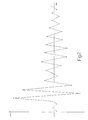
- Fig. 2 is a diagram showing the variation of the value acc of the angular acceleration of the drive shaft 4 as a function of the angular position of this drive shaft 4 in the presence of a single misfire.
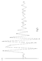
- Fig. 5 is a diagram showing the variation of the value acc of the angular acceleration of the drive shaft 4 as a function of the angular position of this drive shaft 4 in the presence of a double misfire.
- the norm (or absolute value) of each value acc of the angular acceleration of the drive shaft 4 is compared with a predetermined threshold value S which is preferably a function of the current engine point; the presence of misfiring is detected if the absolute value acc of the angular acceleration of the drive shaft 4 is greater than the predetermined threshold value S.
- a predetermined threshold value S which is preferably a function of the current engine point
- a set of eight values acc of the angular acceleration of the drive shaft 4 subsequent to the value acc of the angular acceleration of the drive shaft 4 at which misfiring has been detected are filtered in order to eliminate the oscillation component caused by the misfire with respect to the value acc of the angular acceleration of the drive shaft 4; only the eight filtered values acc of the angular acceleration of the drive shaft 4 are then compared with the threshold value S to detect the presence of any subsequent misfires following the misfire detected.
- the number of values acc of the angular acceleration of the drive shaft 4 to which filtering is applied may be other than eight and is generally between three and twelve; eight are preferably chosen bearing in mind that, in general, the oscillatory phenomenon of the value acc of the angular acceleration of the drive shaft 4 dies out within this duration.
- the eight values acc of the angular acceleration of the drive shaft 4 following the value acc of the angular acceleration of the drive shaft 4 at which the misfire has been detected are filtered by algebraically adding a corresponding set of eight correction values to these values; these correction values are obtained at the design and development stage of the engine 1 by analysing the oscillation generated by a misfire with respect to the value acc of the angular acceleration of the drive shaft 4.
- the correction values may for instance be calculated by subtracting a corresponding set of values acc of the angular acceleration of the drive shaft 4 in the presence of a misfire from a set of values acc of the angular acceleration of the drive shaft 4 in standard conditions.
- Fig. 3 is a diagram showing a set of eight correction values as a function of the angular position of the drive shaft 4.
- the method described above to improve the ability to diagnose misfiring entails the isolation of the oscillatory disturbance which takes place with respect to the value acc of the angular acceleration of the drive shaft 4 following a single misfire and the successive use of this oscillatory disturbance to filter a set of eight values acc of the angular acceleration of the drive shaft 4 following each misfire.
- Fig. 4 is a diagram showing the variation of the value acc of the angular acceleration of the drive shaft 4 of Fig. 2 after the application of the filtering process, i.e. after the eight correction values of Fig. 3 have been algebraically added to the values acc of the angular acceleration of the drive shaft 4 of Fig. 2.
- Fig. 6 is a diagram showing the variation of the value acc of the angular acceleration of the drive shaft 4 of Fig. 5 after the application of the filtering process, i.e. after the eight correction values of Fig. 3 have been algebraically added to the values acc of the angular acceleration of the drive shaft 4 of Fig. 5.
- the correction values have to be variable as a function of the engine point. For this reason, at the design stage of the engine 1, a plurality of salient engine points are identified, at each of which the corresponding sample set of correction values is calculated; during normal operation of the engine 1, the set of correction values corresponding to the current engine point is calculated by interpolating the sample sets of correction values. As an alternative, at the design stage of the engine 1, a pluralityof salient engine points are identified, at each of which the corresponding sample set of correction values is calculated, and a single standard reference set independent from the engine point is calculated from the sample sets of correction values; during normal operation of the engine 1, the set of correction values corresponding to the current engine point is calculated from the standard reference set.
- the set of values acc of the angular acceleration of the drive shaft 4 and the set of correction values are expressed as angular acceleration of the drive shaft 4 as a function of the angular position of this drive shaft 4, while the standard reference set is expressed as a ratio between angular acceleration of the drive shaft 4 and engine load 1 as a function of time.
- the engine load 1 is preferably indicated by the flow of fresh air supplied to the engine 1.
Landscapes
- Chemical & Material Sciences (AREA)
- Engineering & Computer Science (AREA)
- Combustion & Propulsion (AREA)
- Physics & Mathematics (AREA)
- General Physics & Mathematics (AREA)
- Combined Controls Of Internal Combustion Engines (AREA)
- Ignition Installations For Internal Combustion Engines (AREA)
- Testing Of Engines (AREA)
Description
- The present invention relates to a method for detecting misfiring in an internal combustion engine by analysing the angular acceleration of the drive shaft.
- In an internal combustion engine with controlled ignition, the term misfire or misfiring indicates a phenomenon of incorrect combustion within one or more cylinders; the misfire is in particular known as an ignition misfire when it is due to the inadequate or lacking energy of the spark generated by the spark plug, and is known as an injection misfire when it is due to a fuel supply which is inadequate or lacking.
- The presence of a misfire is particularly damaging since incorrect combustion is detrimental to engine performance, increases the level of pollutant emissions from the engine and may cause permanent damage to the catalyst. For this reason, European standards on automobile vehicle emission limits require misfiring to be detected efficiently and for drivers to be informed of the presence of a misfire by means of an indicator light disposed on the dashboard. In particular, it is necessary, under European regulations on automobile vehicle emission limits, to indicate an increase in pollutant emission levels when the number of misfires in a first interval (for instance 1000 TDC - top dead centres) exceeds a first threshold, and to indicate permanent deterioration of the catalyst when the number of misfires in a second interval (for instance 200 TDC - top dead centres) exceeds a second threshold.
- At present, misfiring is detected indirectly, i.e. by analysing the instantaneous value of the angular acceleration of the drive shaft or the instantaneous value of the drive torque, as a direct analysis of combustion by means of sensors disposed inside each cylinder is not practicable for reasons of cost.
- The most widespread method for detecting misfiring involves analysing the angular acceleration of the drive shaft; in particular, the signal supplied by the phonic wheel is used to calculate the value of the angular acceleration of the drive shaft at predetermined angular positions of this drive shaft, and misfiring is detected if the absolute value of the angular acceleration of the drive shaft is higher than a predetermined threshold value.
- It has been observed, however, that this method is not very reliable as the absolute value of the angular acceleration of the drive shaft may also exceed the threshold value as a result of causes unconnected with misfiring, such as, for instance, the coupling or uncoupling of the compressor of the air conditioning plant, the roughness of the road, or even abrupt decelerations. Moreover, in the case of a single misfire, the value of the angular acceleration of the drive shaft may be supplemented by torsional oscillations which cause the absolute value of the angular acceleration of the drive shaft to exceed the threshold value at several successive instants; in this case, a single misfire is erroneously detected as a plurality of successive misfires.
- A first solution to the problems discussed above is disclosed in European Patent Application EP-0637738-A1 which discloses a method for detecting misfiring in an internal combustion engine by analysing the angular acceleration of the drive shaft; in order to try to eliminate the influence of disturbances, the value of the angular acceleration of the drive shaft is processed by creating a so-called cyclicity index which, compared with appropriate thresholds, indicates the presence of misfiring.
- However, the method for detecting misfiring as disclosed in European Patent Application EP-0637738-A1 also tends erroneously to detect a plurality of successive misfires rather than a single misfire as a result of the oscillations of the value of the angular acceleration or the shaft triggered by a misfire.
- The object of the present invention is to provide a method for detecting misfiring in an internal combustion engine by analysing the angular acceleration of the drive shaft, which is free from the drawbacks described above and, in particular, is simple and economic to produce and is able to reduce to a minimum the percentages of incorrect and failed detections of misfiring.
- The present invention relates to a method for detecting misfiring in an internal combustion engine by analysing the angular acceleration of the drive shaft as set out in claim 1.
- The present invention will now be described with reference to the accompanying drawings, which show a non-limiting embodiment thereof, in which:
- Fig. 1 is a diagrammatic view, in lateral elevation and cross-section, of an internal combustion engine provided with a control unit which implements the method for detecting misfiring of the present invention;
- Fig. 2 is a diagram showing the variation of the value of the angular acceleration of the drive shaft as a function of the angular position of this drive shaft in the presence of a single misfire;
- Fig. 3 is a diagram showing a set of eight correction values used by the control unit of Fig 1;
- Fig. 4 is a diagram showing the variation of the value of the angular acceleration of the drive shaft of Fig. 2 after the application of a filtering process using the eight correction values of Fig. 3;
- Fig. 5 is a diagram showing the variation of the value of the angular acceleration of the drive shaft as a function of the angular position of this drive shaft in the presence of a double misfire;
- Fig. 6 is a diagram showing the variation of the value of the angular acceleration of the drive shaft of Fig. 5 after the application of a filtering process using the eight correction values of Fig. 3.
- In Fig. 1, a petrol-driven internal combustion engine is shown overall by 1 and comprises four cylinders 2, each of which houses a respective piston 3 mechanically connected to a drive shaft 4 in order to transmit the force generated by the combustion of the petrol in the cylinder 2 to the drive shaft 4. A phonic wheel 5 provided with 60 teeth 6 and coupled to a sensor 7 adapted to detect the time interval between the passage of two consecutive teeth 6 is keyed on the drive shaft 4. The engine 1 further comprises a control unit 8, which is connected to the sensor 7 and is adapted to detect misfiring in the cylinders 2.
- The methods used by the control unit 8 to detect misfiring, using the information supplied by the sensor 7 coupled to the phonic wheel 5, are described below.
- For each complete rotation of the drive shaft 4 (and therefore of the phonic wheel 5), as many values acc of the angular acceleration of the drive shaft 4 are estimated as there are cylinders 2 performing combustion during a complete rotation of the drive shaft 4; with reference to the engine 1 shown in Fig. 1, two values acc of the angular acceleration of the drive shaft 4 are therefore estimated for each complete rotation of the drive shaft 4.
- In each complete rotation of the drive shaft 4, two (equal to the number of cylinders 2 performing combustion during a complete rotation of the drive shaft 4) angular measurement sections having the same amplitude are identified, the time taken by the drive shaft 4 to travel each angular measurement section is measured, and the value acc of the angular acceleration of the drive shaft 4 at the ith instant is calculated by applying the following formula:

in which: - acci is the angular acceleration of the drive shaft 4 at the ith instant;
- Ti+1 is the time taken by the drive shaft 4 to travel the (i+1)th angular measurement section;
- Ti is the time taken by the drive shaft 4 to travel the ith angular measurement section.
- The time taken by the drive shaft 4 to travel each angular measurement section is measured using the signal supplied by the phonic wheel 5; by way of indication, each angular measurement section has an angular amplitude equal to a number of teeth 6 of the phonic wheel 5 of between 3 and 12. Preferably, each angular measurement section coincides substantially with the expansion stroke of a respective piston 3 or is at least partially superimposed on the expansion stroke of a respective piston 3.
- Fig. 2 is a diagram showing the variation of the value acc of the angular acceleration of the drive shaft 4 as a function of the angular position of this drive shaft 4 in the presence of a single misfire. Fig. 5 is a diagram showing the variation of the value acc of the angular acceleration of the drive shaft 4 as a function of the angular position of this drive shaft 4 in the presence of a double misfire.
- It will be appreciated from Figs. 2 and 5 that, following a misfire, the value acc of the angular acceleration of the drive shaft 4 presents a sequence of high values which tend gradually to fade, i.e. have a curve of a damped oscillatory type.
- The norm (or absolute value) of each value acc of the angular acceleration of the drive shaft 4 is compared with a predetermined threshold value S which is preferably a function of the current engine point; the presence of misfiring is detected if the absolute value acc of the angular acceleration of the drive shaft 4 is greater than the predetermined threshold value S. When misfiring is detected, i.e. when an absolute value acc of the angular acceleration of the drive shaft 4 exceeds the threshold value S, a set of eight values acc of the angular acceleration of the drive shaft 4 subsequent to the value acc of the angular acceleration of the drive shaft 4 at which misfiring has been detected are filtered in order to eliminate the oscillation component caused by the misfire with respect to the value acc of the angular acceleration of the drive shaft 4; only the eight filtered values acc of the angular acceleration of the drive shaft 4 are then compared with the threshold value S to detect the presence of any subsequent misfires following the misfire detected.
- It will be appreciated that the number of values acc of the angular acceleration of the drive shaft 4 to which filtering is applied may be other than eight and is generally between three and twelve; eight are preferably chosen bearing in mind that, in general, the oscillatory phenomenon of the value acc of the angular acceleration of the drive shaft 4 dies out within this duration.
- The eight values acc of the angular acceleration of the drive shaft 4 following the value acc of the angular acceleration of the drive shaft 4 at which the misfire has been detected are filtered by algebraically adding a corresponding set of eight correction values to these values; these correction values are obtained at the design and development stage of the engine 1 by analysing the oscillation generated by a misfire with respect to the value acc of the angular acceleration of the drive shaft 4. The correction values may for instance be calculated by subtracting a corresponding set of values acc of the angular acceleration of the drive shaft 4 in the presence of a misfire from a set of values acc of the angular acceleration of the drive shaft 4 in standard conditions.
- By way of example, Fig. 3 is a diagram showing a set of eight correction values as a function of the angular position of the drive shaft 4.
- In other words, the method described above to improve the ability to diagnose misfiring entails the isolation of the oscillatory disturbance which takes place with respect to the value acc of the angular acceleration of the drive shaft 4 following a single misfire and the successive use of this oscillatory disturbance to filter a set of eight values acc of the angular acceleration of the drive shaft 4 following each misfire.
- Fig. 4 is a diagram showing the variation of the value acc of the angular acceleration of the drive shaft 4 of Fig. 2 after the application of the filtering process, i.e. after the eight correction values of Fig. 3 have been algebraically added to the values acc of the angular acceleration of the drive shaft 4 of Fig. 2. Fig. 6 is a diagram showing the variation of the value acc of the angular acceleration of the drive shaft 4 of Fig. 5 after the application of the filtering process, i.e. after the eight correction values of Fig. 3 have been algebraically added to the values acc of the angular acceleration of the drive shaft 4 of Fig. 5.
- It will be appreciated from an examination of Figs. 4 and 6 that the filtering method described above enables error-free detection of single or multiple misfires; in practice, the above-descried filtering makes it possible to eliminate the possibility of the control unit 8 confusing a single misfire with a multiple misfire.
- In order to ensure that the detection of misfires is very reliable, the correction values have to be variable as a function of the engine point. For this reason, at the design stage of the engine 1, a plurality of salient engine points are identified, at each of which the corresponding sample set of correction values is calculated; during normal operation of the engine 1, the set of correction values corresponding to the current engine point is calculated by interpolating the sample sets of correction values. As an alternative, at the design stage of the engine 1, a pluralityof salient engine points are identified, at each of which the corresponding sample set of correction values is calculated, and a single standard reference set independent from the engine point is calculated from the sample sets of correction values; during normal operation of the engine 1, the set of correction values corresponding to the current engine point is calculated from the standard reference set. In particular, the set of values acc of the angular acceleration of the drive shaft 4 and the set of correction values are expressed as angular acceleration of the drive shaft 4 as a function of the angular position of this drive shaft 4, while the standard reference set is expressed as a ratio between angular acceleration of the drive shaft 4 and engine load 1 as a function of time. The engine load 1 is preferably indicated by the flow of fresh air supplied to the engine 1.
- Experimental tests have shown that the use of a standard reference set of correction values in place of a plurality of sample sets of correction values makes it possible considerably to reduce the memory occupation of the control unit 8 without substantial effects on the reliability and accuracy of the filtering method.
Claims (15)
- A method for detecting misfiring in an internal combustion engine (1) by analysing the angular acceleration (acc) of the drive shaft (4), in which the value (acc) of the angular acceleration of the drive shaft (4) is estimated at predetermined angular positions of this drive shaft (4), the absolute value (acc) of the angular acceleration of the drive shaft (4) is compared with a predetermined threshold value (S), and the presence of a misfire is detected if the absolute value (acc) of the angular acceleration of the drive shaft (4) is greater than the predetermined threshold value (S), characterised in that when the presence of a misfire is detected, i.e. when an absolute value (acc) of the angular acceleration of the drive shaft (4) exceeds the threshold value (S), a set of values (acc) of the angular acceleration of the drive shaft (4) subsequent to the value (acc) of the angular acceleration of the drive shaft (4) at which the misfire has been detected is filtered to eliminate the oscillation component generated by the misfire with respect to the value (acc) of the angular acceleration of the drive shaft (4), only the filtered values (acc) of the angular acceleration of the drive shaft (4) being compared with the threshold value (S) to detect the presence of any further misfires subsequent to the misfire detected.
- A method as claimed in claim 1, in which the values (acc) of the angular acceleration of the drive shaft (4) subsequent to the value (acc) of the angular acceleration of the drive shaft (4) at which the misfire has been detected are filtered by algebraically adding to these values a corresponding set of correction values obtained at the design and development stage of the engine (1) by analysing the oscillation generated by a misfire with respect to the value (acc) of the angular acceleration of the drive shaft (4).
- A method as claimed in claim 2, in which the correction values are calculated by subtracting a corresponding set of values (acc) of the angular acceleration of the drive shaft (4) in the presence of a misfire from a set of values (acc) of the angular acceleration of the drive shaft (4) in standard conditions.
- A method as claimed in claim 2 or 3, in which the correction values are variable as a function of the current engine point.
- A method as claimed in claim 4, in which, at the design stage of the engine (1), a plurality of salient engine points are identified, at each of which the corresponding sample set of correction values is calculated, and during the normal operation of the engine (1), the set of correction values for the current engine point is calculated by interpolating the sample sets of correction values.
- A method as claimed in claim 4, in which, at the design stage of the engine (1), a plurality of salient engine points are identified, at each of which the corresponding sample set of correction values is calculated, and a single standard reference set independent from the engine point is calculated from the sample sets of correction values, and during the normal operation of the engine (1), the set of correction values for the current engine point is calculated from the standard reference set.
- A method as claimed in claim 6, in which the set of values (acc) of the angular acceleration of the drive shaft (4) and the set of correction values are expressed as angular acceleration of the drive shaft (4) as a function of the angular position of the drive shaft (4), the standard reference set being expressed as a ratio between angular acceleration of the drive shaft (4) and engine load (1) as a function of time.
- A method as claimed in claim 7, in which the engine load (1) is indicated by the flow of fresh air supplied to the engine (1).
- A method as claimed in one of claims 1 to 8, in which a set of eight values (acc) of the angular acceleration of the drive shaft (4) are filtered from the value (acc) of the angular acceleration of the drive shaft (4) at which the misfire has been detected.
- A method as claimed in one of claims 1 to 9, in which the threshold value (S) for the detection of the misfire is a function of the current engine point.
- A method as claimed in one of claims 1 to 10, in which, for each complete rotation of the drive shaft (4), as many values (acc) of the angular acceleration of the drive shaft (4) are estimated as there are cylinders (2) performing combustion during a complete rotation of the drive shaft (4).
- A method as claimed in one of claims 1 to 11, in which, in each complete rotation of the drive shaft (4), as many angular measurement sections having the same amplitude are identified as there are cylinders (2) performing combustion during a complete rotation of the drive shaft (4), the time taken by the drive shaft (4) to travel each angular measurement section being measured, and the value (acc) of the angular acceleration of the drive shaft (4) at the ith instant being calculated by applying the following formula:

in which:acci is the angular acceleration of the drive shaft (4) at the ith instant;Ti+1 is the time taken by the drive shaft (4) to travel the (i+1)th angular measurement section;Ti is the time taken by the drive shaft (4) to travel the ith angular measurement section. - A method as claimed in claim 12, in which the time taken by the drive shaft (4) to travel each angular measurement section is measured using the signal supplied by the phonic wheel (5) which is provided with a disc having 60 teeth (6), each angular measurement section having an angular amplitude equal to a number of teeth (6) of the phonic wheel (12) of between 3 and 12.
- A method as claimed in claim 12 or 13, in which each angular section is at least partially superimposed with respect to the expansion stroke of a respective piston (3).
- A method as claimed in claim 12 or 13, in which each angular section substantially coincides with the expansion stroke of a respective piston (3).
Applications Claiming Priority (2)
| Application Number | Priority Date | Filing Date | Title |
|---|---|---|---|
| ITBO20030055 | 2003-02-07 | ||
| IT000055A ITBO20030055A1 (en) | 2003-02-07 | 2003-02-07 | METHOD FOR THE RECOGNITION OF THE MISFIRE IN PHENOMENON |
Publications (3)
| Publication Number | Publication Date |
|---|---|
| EP1447655A2 EP1447655A2 (en) | 2004-08-18 |
| EP1447655A3 EP1447655A3 (en) | 2005-01-19 |
| EP1447655B1 true EP1447655B1 (en) | 2006-06-07 |
Family
ID=32676826
Family Applications (1)
| Application Number | Title | Priority Date | Filing Date |
|---|---|---|---|
| EP04100439A Expired - Lifetime EP1447655B1 (en) | 2003-02-07 | 2004-02-05 | Method for detecting misfiring in an internal combustion engine by analysing the angular acceleration of the drive shaft |
Country Status (6)
| Country | Link |
|---|---|
| US (1) | US7024303B2 (en) |
| EP (1) | EP1447655B1 (en) |
| BR (1) | BRPI0400637B1 (en) |
| DE (1) | DE602004001064T2 (en) |
| ES (1) | ES2264083T3 (en) |
| IT (1) | ITBO20030055A1 (en) |
Families Citing this family (7)
| Publication number | Priority date | Publication date | Assignee | Title |
|---|---|---|---|---|
| ITBO20030055A1 (en) * | 2003-02-07 | 2004-08-08 | Magneti Marelli Powertrain Spa | METHOD FOR THE RECOGNITION OF THE MISFIRE IN PHENOMENON |
| EP1843024B1 (en) * | 2006-04-06 | 2017-07-26 | Magneti Marelli S.p.A. | Power train control method and system |
| FR2918748A1 (en) * | 2007-07-10 | 2009-01-16 | Peugeot Citroen Automobiles Sa | Heat engine cyclic irregularity measuring method for e.g. hybrid vehicle, involves comparing measured acceleration with threshold value, and triggering alarm system during exceeding of measured acceleration than threshold value |
| EP2485034B1 (en) | 2011-02-02 | 2015-08-05 | agrogen GmbH | Method for cylinder-selective recognition of misfires |
| ITTO20110770A1 (en) | 2011-08-12 | 2013-02-13 | Magneti Marelli Spa | METHOD FOR RECOGNIZING THE MISFIRE PHENOMENON IN AN INTERNAL COMBUSTION ENGINE |
| ITBO20120345A1 (en) * | 2012-06-22 | 2013-12-23 | Magneti Marelli Spa | METHOD FOR RECOGNIZING THE MISFIRE PHENOMENON IN AN INTERNAL COMBUSTION ENGINE |
| JP2025087309A (en) * | 2023-11-29 | 2025-06-10 | ヤマハ発動機株式会社 | Method and system for controlling a marine propulsion device - Patents.com |
Family Cites Families (7)
| Publication number | Priority date | Publication date | Assignee | Title |
|---|---|---|---|---|
| EP0583495B1 (en) * | 1992-08-14 | 1996-01-10 | Siemens Aktiengesellschaft | Method for the detection and correction of errors in time measurements of rotating shafts |
| DE4239055C1 (en) * | 1992-11-20 | 1994-04-07 | Audi Ag | Detecting and quantifying misfire's in I.C. engine - employing crankshaft speed sensor and paired counters for discriminating between genuine and apparent combustion irregularities. |
| IT1260957B (en) | 1993-08-04 | 1996-04-29 | Fiat Ricerche | PROCEDURE AND SYSTEM FOR DETECTION OF FAILURE IN COMBUSTION IN INTERNAL COMBUSTION ENGINES. |
| JP3381179B2 (en) * | 1993-10-05 | 2003-02-24 | 株式会社日立製作所 | Vehicle state detection device and detection method |
| US5602331A (en) * | 1995-06-06 | 1997-02-11 | Chrysler Corporation | Engine misfire detection with cascade filter configuration |
| JPH1018900A (en) * | 1996-07-03 | 1998-01-20 | Nissan Motor Co Ltd | Diagnostic device for detecting means and misfire diagnostic device for engine |
| ITBO20030055A1 (en) * | 2003-02-07 | 2004-08-08 | Magneti Marelli Powertrain Spa | METHOD FOR THE RECOGNITION OF THE MISFIRE IN PHENOMENON |
-
2003
- 2003-02-07 IT IT000055A patent/ITBO20030055A1/en unknown
-
2004
- 2004-02-05 DE DE602004001064T patent/DE602004001064T2/en not_active Expired - Lifetime
- 2004-02-05 ES ES04100439T patent/ES2264083T3/en not_active Expired - Lifetime
- 2004-02-05 EP EP04100439A patent/EP1447655B1/en not_active Expired - Lifetime
- 2004-02-06 US US10/773,858 patent/US7024303B2/en not_active Expired - Lifetime
- 2004-02-09 BR BRPI0400637-2A patent/BRPI0400637B1/en not_active IP Right Cessation
Also Published As
| Publication number | Publication date |
|---|---|
| DE602004001064T2 (en) | 2007-12-13 |
| ITBO20030055A1 (en) | 2004-08-08 |
| ES2264083T3 (en) | 2006-12-16 |
| BRPI0400637B1 (en) | 2015-03-17 |
| US7024303B2 (en) | 2006-04-04 |
| EP1447655A3 (en) | 2005-01-19 |
| EP1447655A2 (en) | 2004-08-18 |
| BRPI0400637A (en) | 2005-05-24 |
| US20040220719A1 (en) | 2004-11-04 |
| DE602004001064D1 (en) | 2006-07-20 |
Similar Documents
| Publication | Publication Date | Title |
|---|---|---|
| Klenk et al. | Misfire detection by evaluating crankshaft speed-a means to comply with OBDII | |
| EP0677165B1 (en) | System to determine engine misfire | |
| US5841025A (en) | Misfire detection method and apparatus | |
| US5515281A (en) | Process and system for detecting misfiring in internal combustion engines | |
| US5893897A (en) | Method of detecting combustion misfires by evaluating RPM fluctuations | |
| US6725709B2 (en) | Combustion state diagnosing system and combustion state diagnosing method for diagnosing engine and recording medium | |
| US6591666B1 (en) | Engine misfire detection using adjustable windowing | |
| US7024303B2 (en) | Method for detecting misfiring in an internal combustion engine by analysing the angular acceleration of the drive shaft | |
| JPH09126042A (en) | How to detect combustion misfire | |
| US5602331A (en) | Engine misfire detection with cascade filter configuration | |
| EP2557408B1 (en) | A method for detecting a misfire condition in an internal combustion engine | |
| EP0660099B1 (en) | Misfire detection in internal combustion engine | |
| DE102009049544A1 (en) | Method for detecting misfires | |
| KR20050103949A (en) | Method for detecting combustion failure by filtering | |
| US5821411A (en) | Method for detecting combustion misfires via a separate classification of individual and permanent misfires | |
| EP1515130B1 (en) | Method for finding the angular acceleration of a drive shaft of an internal combustion engine by means of a gear wheel integral with said drive shaft | |
| EP2163856B1 (en) | Method for determining the angular position of a drive shaft of an internal combustion engine | |
| US6837100B1 (en) | Detection of combustion misfiring | |
| WO2006054928A1 (en) | Method for determination of mean engine torque | |
| JP2001515994A (en) | Method for detecting abnormal disturbance of torque of internal combustion engine | |
| KR100282895B1 (en) | Engine misfire detection device and method | |
| KR102667018B1 (en) | Misfire diagnosis method and device of engine | |
| JPH05263709A (en) | Burning state detecting device for internal combustion engine | |
| Cavina et al. | A Methodology for Increasing the Signal to Noise Ratio for the Misfire Detection at High Speed in a High Performance Engine | |
| JP2001152953A (en) | Engine misfire diagnosis device |
Legal Events
| Date | Code | Title | Description |
|---|---|---|---|
| PUAI | Public reference made under article 153(3) epc to a published international application that has entered the european phase |
Free format text: ORIGINAL CODE: 0009012 |
|
| AK | Designated contracting states |
Kind code of ref document: A2 Designated state(s): AT BE BG CH CY CZ DE DK EE ES FI FR GB GR HU IE IT LI LU MC NL PT RO SE SI SK TR |
|
| AX | Request for extension of the european patent |
Extension state: AL LT LV MK |
|
| PUAL | Search report despatched |
Free format text: ORIGINAL CODE: 0009013 |
|
| AK | Designated contracting states |
Kind code of ref document: A3 Designated state(s): AT BE BG CH CY CZ DE DK EE ES FI FR GB GR HU IE IT LI LU MC NL PT RO SE SI SK TR |
|
| AX | Request for extension of the european patent |
Extension state: AL LT LV MK |
|
| 17P | Request for examination filed |
Effective date: 20050701 |
|
| AKX | Designation fees paid |
Designated state(s): DE ES FR GB SE |
|
| GRAP | Despatch of communication of intention to grant a patent |
Free format text: ORIGINAL CODE: EPIDOSNIGR1 |
|
| GRAS | Grant fee paid |
Free format text: ORIGINAL CODE: EPIDOSNIGR3 |
|
| GRAA | (expected) grant |
Free format text: ORIGINAL CODE: 0009210 |
|
| AK | Designated contracting states |
Kind code of ref document: B1 Designated state(s): DE ES FR GB SE |
|
| REG | Reference to a national code |
Ref country code: GB Ref legal event code: FG4D |
|
| REF | Corresponds to: |
Ref document number: 602004001064 Country of ref document: DE Date of ref document: 20060720 Kind code of ref document: P |
|
| REG | Reference to a national code |
Ref country code: SE Ref legal event code: TRGR |
|
| ET | Fr: translation filed | ||
| REG | Reference to a national code |
Ref country code: ES Ref legal event code: FG2A Ref document number: 2264083 Country of ref document: ES Kind code of ref document: T3 |
|
| PLBE | No opposition filed within time limit |
Free format text: ORIGINAL CODE: 0009261 |
|
| STAA | Information on the status of an ep patent application or granted ep patent |
Free format text: STATUS: NO OPPOSITION FILED WITHIN TIME LIMIT |
|
| 26N | No opposition filed |
Effective date: 20070308 |
|
| PGFP | Annual fee paid to national office [announced via postgrant information from national office to epo] |
Ref country code: SE Payment date: 20091228 Year of fee payment: 7 |
|
| PGFP | Annual fee paid to national office [announced via postgrant information from national office to epo] |
Ref country code: ES Payment date: 20100205 Year of fee payment: 7 |
|
| PGFP | Annual fee paid to national office [announced via postgrant information from national office to epo] |
Ref country code: GB Payment date: 20100128 Year of fee payment: 7 |
|
| REG | Reference to a national code |
Ref country code: SE Ref legal event code: EUG |
|
| GBPC | Gb: european patent ceased through non-payment of renewal fee |
Effective date: 20110205 |
|
| PG25 | Lapsed in a contracting state [announced via postgrant information from national office to epo] |
Ref country code: GB Free format text: LAPSE BECAUSE OF NON-PAYMENT OF DUE FEES Effective date: 20110205 |
|
| REG | Reference to a national code |
Ref country code: ES Ref legal event code: FD2A Effective date: 20120411 |
|
| PG25 | Lapsed in a contracting state [announced via postgrant information from national office to epo] |
Ref country code: ES Free format text: LAPSE BECAUSE OF NON-PAYMENT OF DUE FEES Effective date: 20110206 |
|
| PG25 | Lapsed in a contracting state [announced via postgrant information from national office to epo] |
Ref country code: SE Free format text: LAPSE BECAUSE OF NON-PAYMENT OF DUE FEES Effective date: 20110206 |
|
| REG | Reference to a national code |
Ref country code: FR Ref legal event code: PLFP Year of fee payment: 13 |
|
| REG | Reference to a national code |
Ref country code: FR Ref legal event code: PLFP Year of fee payment: 14 |
|
| REG | Reference to a national code |
Ref country code: FR Ref legal event code: PLFP Year of fee payment: 15 |
|
| PGFP | Annual fee paid to national office [announced via postgrant information from national office to epo] |
Ref country code: DE Payment date: 20220119 Year of fee payment: 19 |
|
| PGFP | Annual fee paid to national office [announced via postgrant information from national office to epo] |
Ref country code: FR Payment date: 20220119 Year of fee payment: 19 |
|
| REG | Reference to a national code |
Ref country code: DE Ref legal event code: R119 Ref document number: 602004001064 Country of ref document: DE |
|
| PG25 | Lapsed in a contracting state [announced via postgrant information from national office to epo] |
Ref country code: FR Free format text: LAPSE BECAUSE OF NON-PAYMENT OF DUE FEES Effective date: 20230228 Ref country code: DE Free format text: LAPSE BECAUSE OF NON-PAYMENT OF DUE FEES Effective date: 20230901 |