EP1447558A1 - Improvements in or relating to pressurisation pumps - Google Patents
Improvements in or relating to pressurisation pumps Download PDFInfo
- Publication number
- EP1447558A1 EP1447558A1 EP04250738A EP04250738A EP1447558A1 EP 1447558 A1 EP1447558 A1 EP 1447558A1 EP 04250738 A EP04250738 A EP 04250738A EP 04250738 A EP04250738 A EP 04250738A EP 1447558 A1 EP1447558 A1 EP 1447558A1
- Authority
- EP
- European Patent Office
- Prior art keywords
- plungers
- plunger
- pump
- fuel
- pumping
- Prior art date
- Legal status (The legal status is an assumption and is not a legal conclusion. Google has not performed a legal analysis and makes no representation as to the accuracy of the status listed.)
- Granted
Links
Images




Classifications
-
- F—MECHANICAL ENGINEERING; LIGHTING; HEATING; WEAPONS; BLASTING
- F02—COMBUSTION ENGINES; HOT-GAS OR COMBUSTION-PRODUCT ENGINE PLANTS
- F02M—SUPPLYING COMBUSTION ENGINES IN GENERAL WITH COMBUSTIBLE MIXTURES OR CONSTITUENTS THEREOF
- F02M59/00—Pumps specially adapted for fuel-injection and not provided for in groups F02M39/00 -F02M57/00, e.g. rotary cylinder-block type of pumps
- F02M59/02—Pumps specially adapted for fuel-injection and not provided for in groups F02M39/00 -F02M57/00, e.g. rotary cylinder-block type of pumps of reciprocating-piston or reciprocating-cylinder type
- F02M59/04—Pumps specially adapted for fuel-injection and not provided for in groups F02M39/00 -F02M57/00, e.g. rotary cylinder-block type of pumps of reciprocating-piston or reciprocating-cylinder type characterised by special arrangement of cylinders with respect to piston-driving shaft, e.g. arranged parallel to that shaft or swash-plate type pumps
- F02M59/06—Pumps specially adapted for fuel-injection and not provided for in groups F02M39/00 -F02M57/00, e.g. rotary cylinder-block type of pumps of reciprocating-piston or reciprocating-cylinder type characterised by special arrangement of cylinders with respect to piston-driving shaft, e.g. arranged parallel to that shaft or swash-plate type pumps with cylinders arranged radially to driving shaft, e.g. in V or star arrangement
-
- F—MECHANICAL ENGINEERING; LIGHTING; HEATING; WEAPONS; BLASTING
- F02—COMBUSTION ENGINES; HOT-GAS OR COMBUSTION-PRODUCT ENGINE PLANTS
- F02M—SUPPLYING COMBUSTION ENGINES IN GENERAL WITH COMBUSTIBLE MIXTURES OR CONSTITUENTS THEREOF
- F02M59/00—Pumps specially adapted for fuel-injection and not provided for in groups F02M39/00 -F02M57/00, e.g. rotary cylinder-block type of pumps
- F02M59/02—Pumps specially adapted for fuel-injection and not provided for in groups F02M39/00 -F02M57/00, e.g. rotary cylinder-block type of pumps of reciprocating-piston or reciprocating-cylinder type
- F02M59/022—Pumps specially adapted for fuel-injection and not provided for in groups F02M39/00 -F02M57/00, e.g. rotary cylinder-block type of pumps of reciprocating-piston or reciprocating-cylinder type having an accumulator storing pressurised fuel during pumping stroke of the piston for subsequent delivery to the injector
-
- F—MECHANICAL ENGINEERING; LIGHTING; HEATING; WEAPONS; BLASTING
- F02—COMBUSTION ENGINES; HOT-GAS OR COMBUSTION-PRODUCT ENGINE PLANTS
- F02M—SUPPLYING COMBUSTION ENGINES IN GENERAL WITH COMBUSTIBLE MIXTURES OR CONSTITUENTS THEREOF
- F02M59/00—Pumps specially adapted for fuel-injection and not provided for in groups F02M39/00 -F02M57/00, e.g. rotary cylinder-block type of pumps
- F02M59/02—Pumps specially adapted for fuel-injection and not provided for in groups F02M39/00 -F02M57/00, e.g. rotary cylinder-block type of pumps of reciprocating-piston or reciprocating-cylinder type
- F02M59/08—Pumps specially adapted for fuel-injection and not provided for in groups F02M39/00 -F02M57/00, e.g. rotary cylinder-block type of pumps of reciprocating-piston or reciprocating-cylinder type characterised by two or more pumping elements with conjoint outlet or several pumping elements feeding one engine cylinder
Definitions
- This invention relates to pressurisation pumps.
- this invention also relates to fuel pumps and especially, but not exclusively, to fuel pumps used with compression ignition internal combustion engines.
- a typical common-rail system comprises a fuel supply pump, a common rail (or accumulator) and injectors all joined by high-pressure piping, an electronic control unit, and electronic driver unit and various sensors.
- the supply pump maintains high fuel pressure inside the rail and fuel is injected by opening and closing an internal electromagnetic valve in each injector.
- the common-rail system enables fuel to be injected into the engine's combustion chambers at very high pressures, so the fuel and air mix more thoroughly and burn more efficiently than previous systems.
- the fuel pump constantly replenishes the common rail with pressurised fuel, high pressure is maintained throughout the engine's range of speeds, thus solving the problem of hesitation on acceleration and improving refinement.
- a pump for pumping fluid comprising a first plunger and a second plunger, each plunger being reciprocable within a respective plunger bore defined by a housing, wherein the first and second plungers together with the bores define, at least in part, a pumping volume.
- the pump further comprises an inlet port and an outlet port wherein an end of the first plunger is arranged to cover the inlet port during a pump delivery stage in which fluid is displaced from the pumping volume, and wherein an end of the second plunger is arranged to cover the outlet port during a pump fill stage in which fuel is drawn into the pumping volume.
- the end of the first plunger and the end of the second plunger are arranged to cover the inlet port and outlet port respectively during a pump transfer stage during which the pumping volume is maintained.
- each plunger i.e. the proximal ends
- the opposing faces of each plunger define the pumping volume together with the plunger bore. It will also be appreciated that any increase in volume due to relative movement between the first and second plungers when the inlet port is at least partially uncovered is reversed by further relative movement between the two plungers whilst the outlet port is at least partially uncovered.
- the first and second plungers are aligned along a common axis.
- first and second plungers are driven by means of a single ring cam.
- first and second plungers may reside and be reciprocable within respective plunger bores that are in a parallel-spaced relationship (side-by-side), wherein the plunger bores are in communication with one another by way of a connecting passage.
- the first and second plungers are adapted to only partially cover the inlet and outlet ports respectively.
- the pump comprises at least two pairs of plungers, each pair of plungers performing, in use, a pumping cycle, each pair of plungers having a respective inlet and outlet port.
- a common rail fuel pressurisation system comprising a pump as described previously.
- a pump comprising a first and a second plunger within a housing, the first and second plungers together comprising a first pair of plungers, communicating means connecting the first and second plungers, an inlet port and an outlet port provided in the communicating means, a proximal end of the first plunger adapted to cover the inlet port, a proximal end of the second plunger adapted to cover the outlet port such that a volume is defined by the communicating means and the proximal ends of the first and second plungers, characterised in that the maximum volume defined while the inlet port is covered is greater than the maximum volume defined when the delivery port is covered.
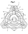
- FIG. 1 a schematic representation of a known type of pressurisation pump, which is the subject of a separate patent application, comprising a pump housing 1 and three radially mounted plunger members 2, each of which is reciprocable within a respective plunger bore 3 provided in the pump housing 1 under the influence of a respective drive arrangement 4, 6 and 7 so as to cause pressurisation of fuel within an associated pumping chamber 5.
- Each drive arrangement includes a cam 4 that is arranged to drive a reciprocable shoe 6 and a roller member 7, the cam being driven, in use, by means of an associated drive shaft 8.
- the roller member 7 is located radially inward of the shoe 6 and is cooperable with a cam surface 4a of the cam 4 so as to impart reciprocable movement to the shoe 6 upon rotation of the drive shaft 8.
- the pump also includes a tubular member 9 which is secured to the pump housing 1 and arranged such that it is substantially coaxial with the drive shaft 8, the tubular member 9 being further arranged such that it guides reciprocal movement of the shoe 6, in use.
- this type of pressurisation pump requires separate mechanical valving means of the type commonly used with internal combustion engines to effect control over inlet and outlet of fuel.
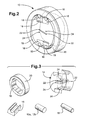
- the pressurisation pump 10 comprises two pairs of plungers, a first pair of plungers 12a and a second pair of plungers 12b.
- the plunger pairs 12a and 12b are mounted in opposed in-line formation within a pump head 14.
- Each plunger approaches its paired plunger at its proximal end and at the distal end connects or is otherwise coupled to a shoe 16.
- Each shoe 16 embraces a respective roller 18, and the head, plungers, shoes and rollers are all mounted with respect to the head as shown such that only the rollers 18 are in contact with a cam surface 19 of a driven ring cam 20.
- the cam surface 19 is also known as the cam profile of the ring cam 20.
- Each pair of plungers resides and is moveable within a respective common bore 26, 28 provided in the pump head 14.
- Biasing means may be employed to ensure that the plungers 12a, 12b are forced radially outwards so that the rollers 18 are in constant contact with the internal surface 19 of the ring cam 20 as it is driven, in use.
- Suitable biasing means may take the form of a resilient spring.
- the internal surface 19 of the ring cam 20 is eccentrically shaped so that rotation of the cam 20 about its central axis, while the pump head 14 remains stationary, imparts a reciprocating motion to the plungers 12a, 12b and the shoes 16 through contact of the cam surface 19 with the rollers 18. This reciprocating motion can be quantized into pumping cycles.
- the ring cam 20 may be shaft-driven or driven by other means commonly employed to drive ancillary equipment relating to compression ignition engines.
- the head 14 comprises four fill ports 22, two of which are located so as to communicate with one of the bores 26 and the other two of which are located so as to communicate with the other one of the bores 28.
- Fill ports 22 are also commonly referred to as inlet ports.
- the fill ports 22 are connected to the outlet of a transfer pump which supplies fuel to the inlet ports 22 at transfer pressure.
- each fill port 22 of one pair and each delivery port 24 of one pair is located diametrically opposite its paired port along the associated bore.
- the fill ports 22 allow fuel to be taken into the bore 26 and the delivery ports 24 allow fuel to be pumped out of the bore 26. It is preferred that pairs of fill and delivery ports are employed, and that each fill or delivery port is diametrically opposite the other port of the pair in its respective bore in order to balance forces generated during fill and delivery stages of the cycle, and so avoiding side-loading of the plungers.
- the delivery ports 24 are also commonly referred to as outlet ports or pumping ports.
- each of the plungers 12a, 12b is able to move within its bore 26, 28 so that all of the ports in that bore can be completely covered by a plunger, thus cutting off flow into or out of the bore 26,28 through that port.
- one plunger of each plunger pair 12a, 12b is responsible for covering the inlet ports 22 and the other plunger out of the plunger pair 12a, 12b is responsible for covering the outlet ports 24.
- Figure 3 shows separately the components referred to in relation to Figure 2 above.
- the bores 26 and 28 are seen in the head 14 in this view.
- Figures 5 to 10 show the salient positions of the plungers 12a and 12b during one pumping cycle of the pressurisation pump shown in Figures 2 and 3.
- the positions shown in Figures 5 to 10 appear in the order in which they occur in a pumping cycle.
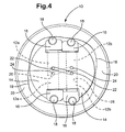
- Figure 5 is an exact reproduction of Figure 4 but shown at a smaller scale.
- motion of only one of the plunger pairs 12a in the bore 26 will be described for clarity, although the other plunger pair 12b in the bore 28 operates in exactly the same manner.
- Figure 5 shows the plunger positions when in a "start fill stage" of the pumping cycle during which the fill ports 22 becomes partially uncovered by one plunger of the pair, while the delivery ports 24 are covered by the other plunger of the pair.
- Relative movement between the two plungers 12a as the cam 20 rotates creates a volume 23 between the proximal ends of the plungers 12a - the volume 23 is not shown in Figure 5 as this is the starting position of the cycle but is shown in Figures 6 to 8 instead.
- the delivery ports 22 are covered the creation of the volume 23 results in fuel being drawn into the volume 23 through the fill ports 22.
- the volume 23 is caused by ingress into the pumping bore 26 of fuel supplied by the transfer pump (not shown) at transfer pressure which forces the two plungers 12a apart. Accordingly in this embodiment there is no need for biasing means to force the two plungers 12a apart.
- the starting position shows that there is no initial volume between the proximal faces of the two plungers 12a. It is envisaged in alternative embodiments that at the starting point of the pumping cycle there already exists a volume 23 between the plungers 12a. In this situation what is required in order to progress to the next stage is simply for an increase in volume to occur due to relative movement between the plungers 12a. Accordingly, in the situation where there is an initial volume between the plungers 12a, when the pumping cycle is complete and the plungers 12a return to the starting position the initial volume 23 between the plungers will be realised again.
- Figure 6 shows the plunger positions during the second stage of the pumping cycle, referred to as "the continue fill” stage. Fuel continues to flow into the bore 26 during the continue fill stage as the volume 23 increases to its maximum size as shown in Figure 6. As the continue fill stage is completed the fill ports 22 become covered by one of the plungers of the pair. During the continue fill stage the delivery ports 24 stay fully covered.
- Figure 7 shows the plunger positions when in the third stage of the pumping cycle referred to as the "transfer ports" stage during which the fill ports 22 and the delivery ports 24 are all fully covered. Throughout this stage the size of the volume 23 is maintained at a substantially constant value due to the essentially incompressible nature of the fuel being transferred in the bore 26. Thus, both plungers move substantially in unison along the bores 26, 28.
- the fluid to be pumped can be compressible, for example a gaseous fuel/air mixture.
- the volume 23 during the transfer ports stage can vary, perhaps providing additional compression to the delivery pressure that is achieved during the delivery phase.
- Figure 8 shows the plunger positions at the end of the transfer ports stage as the cycle moves into the "start delivery" stage.
- the delivery ports 24 start to become uncovered while the fill ports 22 remain fully covered.
- the volume 23 diminishes as the plungers 12a of the pair start to move relative to one another, with relative movement between the two plungers 12a and the accompanying reduction in size of the volume 23 causing the fuel residing in the volume 23 to be ejected out of the bore 26 via the delivery ports 24.
- Figure 9 shows the position of the plungers once all the required fuel has been delivered from the bore, and this stage of the pumping cycle is known as the "end delivery" stage. This stage is arrived at following the start delivery stage by continued relative movement between the plungers 12a. The relative movement between the plungers 12a results in a decrease in size of the volume 23 and as the fill ports 22 are fully covered this causes the fuel residing in the volume 23 to be forced out of the bore 26 via the delivery ports 24 under high pressure. In the embodiment shown in Figure 9, all the fuel transferred into the bore 26 during the transfer stage has been forced out of the bore by the time the end delivery stage is over.
- Figure 10 is the last stage in the cycle as both plungers 12a are moved in unison back to the start fill position again.
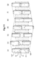
- Figures 11(a) to 11(g) show in greater detail the positions of one set of opposed in-line plungers 12a, 12b relative to their respective fill and delivery ports 22, 24 during the cycle described in Figures 5 to 10 above.
- Figure 11(a) shows the pair of opposing in-line plungers 12a, further distinguished as comprising a fill plunger 12aF and a pumping plunger 12aP.
- Figure 11(a) shows the plungers 12aF and 12aP just prior to the start fill stage. It is to be noted that in Figure 11(a) there exists an initial volume 23 at the start of the pumping cycle even though the plungers 12aF and 12aP are in contact with each other. This is due to the configuration of the plunger head chosen, wherein the heads comprise a tapered head that terminates at a shoulder.
- both plungers move in unison towards the fill ports 22 and once the fill ports are at least partially uncovered by the full plunger 12aF, relative movement between the two plungers 12aF and 12aP can occur which draws fuel into the bore 26 through the fill ports 22.
- Figure 11(f) shows the plunger 12aF returning toward the fill ports 22 in an opening direction
- Figure 11(g) shows the plungers 12aF, 12aP as they approach the edge of the fill ports 22, ready to restart the pumping cycle.
- Plunger strokes can be achieved by a single cam profile 19 formed on the inside surface of the driven ring cam 20.
- a phase difference between movement of the plungers of each pair 12a, 12b of plungers is generated.
- Figures 12 and 13 show phase differences between the two sets of opposing in-line plungers 12a and 12b corresponding to ⁇ values of 15 degrees and 10 degrees respectively.
- the direction of rotation of the driven ring cam 20 is shown by the arrow ⁇ .
- Another pair of plungers can be run on the reverse side of pump 10 driven by the same or a different cam.
- the modular nature of the invention means that further pump units can be arranged together in series, axially spaced along a cam drive shaft, to form a compact unit to provide the desired output of pressurised fuel.
- the pump therefore provides a much smaller and simpler arrangement than previously available.
- the addition of further pumping units has the further advantage of smoothing and refining the resulting operation of all the pumps so connected.
- Figure 14 shows the projected displacement and swept volume data during a pumping stroke for an idealised pressurisation pump according to Figures 2 to 13, assuming zero plunger inertia and idealised 'triangular' movement plots.
- Figure 15 highlights possible problems with plungers 12a, 12b having a nose radius of 8mm in a 120 degree off-set configuration
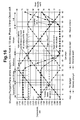
- Figure 16 shows how such problems may be solved by moving to a 130 degree off-set configuration with a reduced distance between the fill and delivery ports.
- Figure 17 shows an alternative embodiment of the present invention which differs to previous embodiment of the invention in that the first and second plungers 12aF, 12aP reside and are reciprocable within parallel-spaced first and second plunger bores 26, 28, rather than in-line.
- the plungers 12aF, 12aP are therefore side-by-side, in a parallel-spaced relationship.
- the first and second plunger bores 26, 28 are connected by way of a communicating means in the form of a connecting passage 36.
- the plungers 12aF and 12aP are biased by resilient means (not shown) towards the direction of cam lobes 30 and 32 and which are connected to a common camshaft 34. Rotation of the camshaft 34 and the cam lobes 30, 32 reciprocates the plungers 12aF and 12aP within their respective bores 26, 28 so as to cause the plungers 12aF and 12aP to cover and uncover the fill and delivery ports 22 and 24 in a phased manner as has been described with reference to Figures 14 to 16. Therefore, a net pumping of fuel is achieved with each pumping stroke.
- the stages of each pumping stroke in this embodiment are the same as those for the embodiment described in Figures 2 to 16.
- biasing means in the form of a resilient spring may be employed within the bore 26 between the facing ends of the plungers 12, 12a and 12b to enlarge the volume 23 so that fuel may be admitted into the bore 26. It is further envisaged that it may be advantageous to employ a combination of these features. Accordingly, it is to be understood that the invention is not to be limited to the specific illustrated embodiment, but only by the scope of the appended claims.
Landscapes
- Engineering & Computer Science (AREA)
- Chemical & Material Sciences (AREA)
- Combustion & Propulsion (AREA)
- Mechanical Engineering (AREA)
- General Engineering & Computer Science (AREA)
- Fuel-Injection Apparatus (AREA)
- Details Of Reciprocating Pumps (AREA)
- Polyesters Or Polycarbonates (AREA)
Abstract
Description
- This invention relates to pressurisation pumps. In particular, this invention also relates to fuel pumps and especially, but not exclusively, to fuel pumps used with compression ignition internal combustion engines.
- In all types of internal combustion engines it is important for fuel economy that as much of, if not all of, the fuel injected into a combustion chamber is consumed during each combustion cycle. As a first step towards that goal it is important that fuel injected into the combustion chamber is atomised as much as possible as this helps the combustion process by increasing the available fuel surface area for oxidation. Another important consideration is to ensure that the fuel is spread as homogeneously as possible throughout the combustion chamber as this aids flame propagation and so improves combustion efficiency. It follows then that for efficient operation the fuel needs to be injected as fast as possible to provide time to diffuse sufficiently before ignition and the fuel also needs to be injected under as high pressure as possible to ensure maximum atomisation. These factors are especially important for compression ignition engines, or diesel engines, as they rely on compressing air in the combustion chamber to high enough pressures so that the accompanying increase in temperature is hot enough to ignite diesel fuel injected into the combustion chamber, without using premixing or other techniques used in modern petrol engines to aid efficient combustion.
- It is also important that the injection phase of each combustion cycle is controlled as tightly as possible to allow accurate fuel metering and ensure that the correct amount of fuel is injected to match engine load requirements,
- In known diesel engine systems fuel travels from a fuel pump to each individual cyiinder of the engine in separate pipes. Fuel injection in the past has been handled by cam-driven injection systems, such as inline pumps, distributor pumps, unit injectors and unit pumps. These systems build up fuel injection pressure for each injection of fuel and are powered by the engine. Fuel metering and pressure build-up are therefore linked and cannot be separated. The injection pressure results from the metered fuel quantity being pushed through the injector nozzle orifice by an injection piston contained in the injector, and as the injection piston velocity is proportional to engine speed, so the resultant fuel pressure is also proportional to engine speed.
- This link between engine speed and injection pressure in previous systems meant that only limited pressure is available at low engine speeds, harming fuel economy and delivering sluggish responsiveness, slow acceleration and a perception of unrefinement to the diesel automobile operator. In addition, in engines running at high speed there is reduced time on offer, compared to engines running at low speeds, for the air and fuel to mix sufficiently to allow complete combustion. It is clear that injection pressure is key to moving the combustion process along at the fast pace demanded by high-speed engines, and decoupling pressure generation from injection is also highly desired for the reasons explained above.
- It was to address the above problems that common-rail diesel systems were developed. A typical common-rail system comprises a fuel supply pump, a common rail (or accumulator) and injectors all joined by high-pressure piping, an electronic control unit, and electronic driver unit and various sensors. The supply pump maintains high fuel pressure inside the rail and fuel is injected by opening and closing an internal electromagnetic valve in each injector. Hence, there is no relationship between engine speed and injection pressure. The common-rail system enables fuel to be injected into the engine's combustion chambers at very high pressures, so the fuel and air mix more thoroughly and burn more efficiently than previous systems. Additionally, as the fuel pump constantly replenishes the common rail with pressurised fuel, high pressure is maintained throughout the engine's range of speeds, thus solving the problem of hesitation on acceleration and improving refinement.
- More recent inventions relating to common rail systems have been those of providing additional pressurisation in the unit injectors and direct fuel injection. However, with all these systems the common goal is to improve fuel economy, reduce emissions, reduce complexity and reduce the weight of the engine and dependent ancillaries.
- Previous fuel pumps used with in line, distributor and common-rail systems used mechanically actuated valves to control input and output fuel from the fuel pump. Mechanical valving inevitably introduces losses through expenditure of energy in opening and closing inlet and outlet valves. Additionally, as these fuel pumps tend to be driven by the engine, utilising engine power to operate mechanical valving systems draws torque from the engine, resulting in less torque being available for useful work and hence, a further reduction in engine efficiency. Known fuel pumps have also tended to be complex and costly units - consequently there is a desire to reduce complexity as it brings obvious attendant advantages to both the manufacturer and consumer in terms of cost and reliability. With increasingly stringent emissions demands placed upon automobile manufacturers weight is also an important issue as weight has a direct effect on fuel consumption. All the desired improvements mentioned above are synergistic to improving efficiency. Furthermore, as the fuel pump in common-rail applications is running at high speed at all times during engine operation, even a small improvement in efficiency will produce appreciable gains over the long term.
- It is with a view to providing a solution to the above problems and to maximise the benefits achievable by common-rail systems that we provide a pump for pumping fluid comprising a first plunger and a second plunger, each plunger being reciprocable within a respective plunger bore defined by a housing, wherein the first and second plungers together with the bores define, at least in part, a pumping volume. The pump further comprises an inlet port and an outlet port wherein an end of the first plunger is arranged to cover the inlet port during a pump delivery stage in which fluid is displaced from the pumping volume, and wherein an end of the second plunger is arranged to cover the outlet port during a pump fill stage in which fuel is drawn into the pumping volume. The end of the first plunger and the end of the second plunger are arranged to cover the inlet port and outlet port respectively during a pump transfer stage during which the pumping volume is maintained.
- It will be appreciated that the opposing faces of each plunger (i.e. the proximal ends) define the pumping volume together with the plunger bore. It will also be appreciated that any increase in volume due to relative movement between the first and second plungers when the inlet port is at least partially uncovered is reversed by further relative movement between the two plungers whilst the outlet port is at least partially uncovered.
- Preferably, the first and second plungers are aligned along a common axis.
- It is also preferred that the first and second plungers are driven by means of a single ring cam.
- Alternatively, the first and second plungers may reside and be reciprocable within respective plunger bores that are in a parallel-spaced relationship (side-by-side), wherein the plunger bores are in communication with one another by way of a connecting passage.
- Advantageously, the first and second plungers are adapted to only partially cover the inlet and outlet ports respectively.
- It is a preferred feature that the pump comprises at least two pairs of plungers, each pair of plungers performing, in use, a pumping cycle, each pair of plungers having a respective inlet and outlet port.
- It is further advantageous that in the pumping cycle referred to above, a pumping cycle phase difference of between 115° to 130° exists between movement of the plungers of each plunger pair.
- In the alternative, it is preferred that in the pumping cycle above a phase difference of 120° or 130° exists between movement of the plungers of each plunger pair.
- In an alternative aspect of the invention, there is also provided a common rail fuel pressurisation system comprising a pump as described previously.
- In a second aspect of the invention, there is provided a pump comprising a first and a second plunger within a housing, the first and second plungers together comprising a first pair of plungers, communicating means connecting the first and second plungers, an inlet port and an outlet port provided in the communicating means, a proximal end of the first plunger adapted to cover the inlet port, a proximal end of the second plunger adapted to cover the outlet port such that a volume is defined by the communicating means and the proximal ends of the first and second plungers, characterised in that the maximum volume defined while the inlet port is covered is greater than the maximum volume defined when the delivery port is covered.
- The present invention is now described with reference to the accompanying figures wherein:
- Figure 1 is a schematic representation of a known compression ignition fuel pressurisation pump for delivering high pressure fuel to a plurality of injectors of a fuel system;
- Figure 2 is a representation of a pressurisation pump according to a first embodiment of the invention;
- Figure 3 shows the embodiment of Figure 2 in exploded form showing principle components including two sets of opposed in-line plungers within a common bore;
- Figure 4 shows a schematic view of the embodiment of Figures 2 and 3 taken at the start of a pumping cycle;
- Figures 5 to 10 show the salient positions during one pumping cycle of the pressurisation pump shown in Figures 2 and 3;
- Figures 11 (a) to 11 (g) show in greater detail the positions of one set of opposed in-line plungers during the cycle shown in Figures 5 to 10;
- Figures 12 and 13 show phase differences corresponding to 15° and 10° respectively between the two sets of opposed in-line plungers in Figures 2 to 10;
- Figures 14 to 16 are projected mappings of displacement and swept volume during a pumping cycle for a pump according to the first embodiment, wherein Figure 14 is for an idealised pump, Figure 15 corresponds to projections for a pump with real-life characteristics and Figure 16 corresponds to projections for a pump with optimised real-life characteristics; and
- Figure 17 shows an alternative embodiment of the present invention wherein the two plungers are in a parallel-spaced relationship.
-
- There is provided at Figure 1 a schematic representation of a known type of pressurisation pump, which is the subject of a separate patent application, comprising a
pump housing 1 and three radially mountedplunger members 2, each of which is reciprocable within arespective plunger bore 3 provided in thepump housing 1 under the influence of arespective drive arrangement pumping chamber 5. Each drive arrangement includes acam 4 that is arranged to drive areciprocable shoe 6 and a roller member 7, the cam being driven, in use, by means of an associateddrive shaft 8. The roller member 7 is located radially inward of theshoe 6 and is cooperable with acam surface 4a of thecam 4 so as to impart reciprocable movement to theshoe 6 upon rotation of thedrive shaft 8. The pump also includes atubular member 9 which is secured to thepump housing 1 and arranged such that it is substantially coaxial with thedrive shaft 8, thetubular member 9 being further arranged such that it guides reciprocal movement of theshoe 6, in use. Although not shown in Figure 1, this type of pressurisation pump requires separate mechanical valving means of the type commonly used with internal combustion engines to effect control over inlet and outlet of fuel. - Turning to Figures 2 to 4, there is shown a representation of a pressurisation pump according to a first embodiment of the invention shown generally at 10. The
pressurisation pump 10 comprises two pairs of plungers, a first pair ofplungers 12a and a second pair ofplungers 12b. Theplunger pairs pump head 14. Each plunger approaches its paired plunger at its proximal end and at the distal end connects or is otherwise coupled to ashoe 16. Eachshoe 16 embraces arespective roller 18, and the head, plungers, shoes and rollers are all mounted with respect to the head as shown such that only therollers 18 are in contact with acam surface 19 of a drivenring cam 20. Thecam surface 19 is also known as the cam profile of thering cam 20. Each pair of plungers resides and is moveable within a respective common bore 26, 28 provided in thepump head 14. - It will be appreciated that in the section shown in Figure 2, the
bores - Biasing means (not shown) may be employed to ensure that the
plungers rollers 18 are in constant contact with theinternal surface 19 of thering cam 20 as it is driven, in use. Suitable biasing means may take the form of a resilient spring. - The
internal surface 19 of thering cam 20 is eccentrically shaped so that rotation of thecam 20 about its central axis, while thepump head 14 remains stationary, imparts a reciprocating motion to theplungers shoes 16 through contact of thecam surface 19 with therollers 18. This reciprocating motion can be quantized into pumping cycles. Thering cam 20 may be shaft-driven or driven by other means commonly employed to drive ancillary equipment relating to compression ignition engines. - In this embodiment the
head 14 comprises fourfill ports 22, two of which are located so as to communicate with one of thebores 26 and the other two of which are located so as to communicate with the other one of thebores 28. Fillports 22 are also commonly referred to as inlet ports. Although not shown in Figures 2 to 4, thefill ports 22 are connected to the outlet of a transfer pump which supplies fuel to theinlet ports 22 at transfer pressure. - For each bore 26 and 28, each fill
port 22 of one pair and eachdelivery port 24 of one pair is located diametrically opposite its paired port along the associated bore. Thus, in Figure 2 only onefill port 22 and onedelivery port 24 for each of thebores fill ports 22 allow fuel to be taken into thebore 26 and thedelivery ports 24 allow fuel to be pumped out of thebore 26. It is preferred that pairs of fill and delivery ports are employed, and that each fill or delivery port is diametrically opposite the other port of the pair in its respective bore in order to balance forces generated during fill and delivery stages of the cycle, and so avoiding side-loading of the plungers. Thedelivery ports 24 are also commonly referred to as outlet ports or pumping ports. - In use, each of the
plungers bore bore plunger pair inlet ports 22 and the other plunger out of theplunger pair outlet ports 24. - Figure 3 shows separately the components referred to in relation to Figure 2 above. The
bores head 14 in this view. - Figures 5 to 10 show the salient positions of the
plungers bore 26 will be described for clarity, although theother plunger pair 12b in thebore 28 operates in exactly the same manner. - Figure 5 shows the plunger positions when in a "start fill stage" of the pumping cycle during which the
fill ports 22 becomes partially uncovered by one plunger of the pair, while thedelivery ports 24 are covered by the other plunger of the pair. Relative movement between the twoplungers 12a as thecam 20 rotates creates avolume 23 between the proximal ends of theplungers 12a - thevolume 23 is not shown in Figure 5 as this is the starting position of the cycle but is shown in Figures 6 to 8 instead. As thedelivery ports 22 are covered the creation of thevolume 23 results in fuel being drawn into thevolume 23 through thefill ports 22. - The
volume 23 is caused by ingress into the pumping bore 26 of fuel supplied by the transfer pump (not shown) at transfer pressure which forces the twoplungers 12a apart. Accordingly in this embodiment there is no need for biasing means to force the twoplungers 12a apart. - In Figure 5 the starting position shows that there is no initial volume between the proximal faces of the two
plungers 12a. It is envisaged in alternative embodiments that at the starting point of the pumping cycle there already exists avolume 23 between theplungers 12a. In this situation what is required in order to progress to the next stage is simply for an increase in volume to occur due to relative movement between theplungers 12a. Accordingly, in the situation where there is an initial volume between theplungers 12a, when the pumping cycle is complete and theplungers 12a return to the starting position theinitial volume 23 between the plungers will be realised again. - Figure 6 shows the plunger positions during the second stage of the pumping cycle, referred to as "the continue fill" stage. Fuel continues to flow into the
bore 26 during the continue fill stage as thevolume 23 increases to its maximum size as shown in Figure 6. As the continue fill stage is completed thefill ports 22 become covered by one of the plungers of the pair. During the continue fill stage thedelivery ports 24 stay fully covered. - Figure 7 shows the plunger positions when in the third stage of the pumping cycle referred to as the "transfer ports" stage during which the
fill ports 22 and thedelivery ports 24 are all fully covered. Throughout this stage the size of thevolume 23 is maintained at a substantially constant value due to the essentially incompressible nature of the fuel being transferred in thebore 26. Thus, both plungers move substantially in unison along thebores - In an alternative application, the fluid to be pumped can be compressible, for example a gaseous fuel/air mixture. In the example of pumping a compressible fluid, the
volume 23 during the transfer ports stage can vary, perhaps providing additional compression to the delivery pressure that is achieved during the delivery phase. - Figure 8 shows the plunger positions at the end of the transfer ports stage as the cycle moves into the "start delivery" stage. At the beginning of the start delivery stage the
delivery ports 24 start to become uncovered while thefill ports 22 remain fully covered. Thevolume 23 diminishes as theplungers 12a of the pair start to move relative to one another, with relative movement between the twoplungers 12a and the accompanying reduction in size of thevolume 23 causing the fuel residing in thevolume 23 to be ejected out of thebore 26 via thedelivery ports 24. - Figure 9 shows the position of the plungers once all the required fuel has been delivered from the bore, and this stage of the pumping cycle is known as the "end delivery" stage. This stage is arrived at following the start delivery stage by continued relative movement between the
plungers 12a. The relative movement between theplungers 12a results in a decrease in size of thevolume 23 and as thefill ports 22 are fully covered this causes the fuel residing in thevolume 23 to be forced out of thebore 26 via thedelivery ports 24 under high pressure. In the embodiment shown in Figure 9, all the fuel transferred into thebore 26 during the transfer stage has been forced out of the bore by the time the end delivery stage is over. - Figure 10 is the last stage in the cycle as both
plungers 12a are moved in unison back to the start fill position again. - It will be appreciated that, during all stages of the pumping cycle, whether the plungers of each pair are moving relative to one another in an approaching or departing direction, or whether they are moving together, movement of the
plungers cam 20 and the profile of thecam surface 19. - It will also be appreciated, bearing in mind the previous description of a prior art pressurisation pump, that in the embodiment described above there is an absence of separate mechanical valving means. Said valving means are not required as, in use, the motion of the
plungers delivery ports - Figures 11(a) to 11(g) show in greater detail the positions of one set of opposed in-
line plungers delivery ports - Figure 11(a) shows the pair of opposing in-
line plungers 12a, further distinguished as comprising a fill plunger 12aF and a pumping plunger 12aP. In this schematic view only one each of the pairs offill ports 22 anddelivery ports 24 is shown, but the other side of the bore 26 (not shown) has a corresponding number of ports in mirrored locations. Figure 11(a) shows the plungers 12aF and 12aP just prior to the start fill stage. It is to be noted that in Figure 11(a) there exists aninitial volume 23 at the start of the pumping cycle even though the plungers 12aF and 12aP are in contact with each other. This is due to the configuration of the plunger head chosen, wherein the heads comprise a tapered head that terminates at a shoulder. - As shown in Figure 11(b), both plungers move in unison towards the
fill ports 22 and once the fill ports are at least partially uncovered by the full plunger 12aF, relative movement between the two plungers 12aF and 12aP can occur which draws fuel into thebore 26 through thefill ports 22. - In Figure 11(c), once the
maximum volume 23 has been achieved thefill ports 22 are closed by further movement of the fill plunger 12aF which covers thefill ports 22 so that no further fuel can enter thebore 26. Transfer of the fuel to thedelivery ports 24 now takes place. The maximum size of thevolume 23 is determined by thecam profile 19 of the ring cam 20 (not shown in this view). It is noted that the maximum size of thevolume 23 does not have to only be arrived at when thefill ports 22 are fully covered: the maximum volume size can be arrived at while thefill ports 22 are still at least partially uncovered. - Once the
delivery ports 24 start to become uncovered by the pumping plunger 12aP, the fuel in thebore 26 starts to be pumped out of thebore 26 owing to relative movement between the two plungers 12aF and 12aP which decreases thevolume 23 between them. Figure 11(d) shows the pumping stage. - As shown in Figure 11(e), further relative movement between the two plungers 12aF and 12aP ends when the
volume 23 is decreased to a predetermined size and all of the fuel that is required to be pumped has been expelled from thebore 26. The minimum gap size (i.e. separation of the ends of a plunger pair) is also determined by thecam profile 19 of ring cam 20 (not shown). By virtue of the fact that the maximum gap size during fuel intake is larger than the minimum gap size during fuel delivery, a net positive pumping displacement of fuel out of thebore 26 is achieved. - Continuing the cycle, Figure 11(f) shows the plunger 12aF returning toward the
fill ports 22 in an opening direction and Figure 11(g) shows the plungers 12aF, 12aP as they approach the edge of thefill ports 22, ready to restart the pumping cycle. - Plunger strokes can be achieved by a
single cam profile 19 formed on the inside surface of the drivenring cam 20. When the axis of a plunger bore is angularly offset from the major axis A (shown in Figures 12 and 13) of thecam 20 by an angle , a phase difference between movement of the plungers of eachpair line plungers ring cam 20 is shown by the arrow ω. - Referring to Figures 12 and 13, for 120 degrees cyclical phase difference between the two plungers of each
pair plungers bores cam 20. For a six lobe cam operating plungers with 120 degrees cyclical phase difference (Figure 13) the plungers need to be 20 degrees out of phase in total - i.e. each bore centreline is 10 degrees offset from the cam centre line ( = 10°). - To double the pump output another pair of plungers can be run on the reverse side of
pump 10 driven by the same or a different cam. The modular nature of the invention means that further pump units can be arranged together in series, axially spaced along a cam drive shaft, to form a compact unit to provide the desired output of pressurised fuel. The pump therefore provides a much smaller and simpler arrangement than previously available. The addition of further pumping units has the further advantage of smoothing and refining the resulting operation of all the pumps so connected. - Figure 14 shows the projected displacement and swept volume data during a pumping stroke for an idealised pressurisation pump according to Figures 2 to 13, assuming zero plunger inertia and idealised 'triangular' movement plots.
- Figure 15 highlights possible problems with
plungers - Figure 17 shows an alternative embodiment of the present invention which differs to previous embodiment of the invention in that the first and second plungers 12aF, 12aP reside and are reciprocable within parallel-spaced first and second plunger bores 26, 28, rather than in-line. The plungers 12aF, 12aP are therefore side-by-side, in a parallel-spaced relationship. The first and second plunger bores 26, 28 are connected by way of a communicating means in the form of a connecting
passage 36. In a manner similar to the embodiment shown in Figures 2 to 16, there are a pair offill ports 22 and a pair ofdelivery ports 24 arranged along thepassage 36 with eachfill port 22 diametrically opposite its paired port across thepassage 36. In Figure 17 only one port of each pair ofports cam lobes common camshaft 34. Rotation of thecamshaft 34 and thecam lobes respective bores delivery ports - It will be understood that various modifications to the aforedescribed embodiments may be made without departing from the scope of the invention as defined by the claims. For example, although the present invention has been illustrated in the context of a fuel pressurisation pump, the same concept works with any fluid which requires pressurised delivery in applications wherein space, weight and mechanical complexity are desired to be kept to a minimum. Additionally, although reference is made throughout to inlet and delivery ports, this should be taken to encompass inlet and delivery slots. The provision of slots in the bore to provide the inlet and delivery "ports" may be advantageous. Furthermore it is to be understood that although the present invention utilises pressurised fuel supplied by a transfer pump to create and enlarge the
volume 23 between theplungers - As mentioned previously and purely as an example of the alternative methods available, it is envisaged that biasing means in the form of a resilient spring may be employed within the
bore 26 between the facing ends of theplungers volume 23 so that fuel may be admitted into thebore 26. It is further envisaged that it may be advantageous to employ a combination of these features. Accordingly, it is to be understood that the invention is not to be limited to the specific illustrated embodiment, but only by the scope of the appended claims.
Claims (10)
- A pump (10) for pumping fluid comprising:wherein the first and second plungers (12a, 12aF, 12aP, 12b) together with the plunger bores (26, 28) define, at least in part, a pumping volume (23);a first plunger (12a, 12aF, 12b) and a second plunger (12a, 12aP, 12b), each plunger being reciprocable within a respective plunger bore (26, 28) defined by a housing (14);
the pump further comprising an inlet port (22) and an outlet port (24);
an end of the first plunger (12a, 12b, 12aF) being arranged to cover the inlet port (22) during a pump delivery stage in which fluid is displaced from the pumping volume (23);
an end of the second plunger (12a, 12b, 12aP) being arranged to cover the outlet port (24) during a pump fill stage in which fuel is drawn into the pumping volume (23);
wherein the end of the first plunger (12a, 12b, 12aF) and the end of the second plunger (12a, 12b, 12aP) are arranged to cover the inlet port (22) and outlet port (24) respectively during a pump transfer stage during which the pumping volume (23) is maintained. - A pump (10) according to claim 1, wherein the first and second plungers (12a, 12aF, 12aP, 12b) are aligned along a common axis.
- A pump (10) according to claim 1 or claim 2, wherein the first and second plungers (12a, 12aF, 12aP, 12b) are driven by means of a single cam ring (20).
- A pump (10) according to claim 1, wherein the first and second plungers (12a, 12aF, 12aP, 12b) are in a parallel-spaced relationship within their plunger bores (26, 28), their respective plunger bores (26, 28) being in communication with one another by way of a connecting passage (36).
- A pump (10) according to any one of claims 1 to 4, wherein the first and second plungers (12a, 12aF, 12aP, 12b) are adapted to only partially cover the inlet and outlet ports (22, 24) respectively.
- A pump (10) according to any one of claims 1 to 5, wherein the pump (10) comprises at least two pairs of plungers (12a, 12aF, 12aP, 12b), each pair of plungers (12a, 12aF, 12aP, 12b) performing, in use, a pumping cycle and each pair of plungers (12a, 12aF, 12aP, 12b) having a respective inlet and outlet port (22, 24).
- A pump (10) according to claim 6 wherein a pumping cycle phase difference of 115° to 130° exists between movement of the plungers of each plunger pair (12a, 12aF, 12aP, 12b).
- A pump (10) according to claim 6 wherein a pumping cycle phase difference () of 120° exists between movement of the plungers of each plunger pair (12a, 12aF, 12aP, 12b).
- A pump (10) according to claim 6 wherein a pumping cycle phase difference () of 130° exists between movement of the plungers of each plunger pair (12a, 12aF, 12aP, 12b).
- A common rail fuel pressurisation system comprising a pump (10) according to any one of claims 1 to 9.
Applications Claiming Priority (2)
| Application Number | Priority Date | Filing Date | Title |
|---|---|---|---|
| GBGB0303603.5A GB0303603D0 (en) | 2003-02-17 | 2003-02-17 | Improvements in or relating to pressurisation pumps |
| GB0303603 | 2003-02-17 |
Publications (2)
| Publication Number | Publication Date |
|---|---|
| EP1447558A1 true EP1447558A1 (en) | 2004-08-18 |
| EP1447558B1 EP1447558B1 (en) | 2011-06-29 |
Family
ID=9953156
Family Applications (1)
| Application Number | Title | Priority Date | Filing Date |
|---|---|---|---|
| EP04250738A Expired - Lifetime EP1447558B1 (en) | 2003-02-17 | 2004-02-11 | Improvements in or relating to pressurisation pumps |
Country Status (4)
| Country | Link |
|---|---|
| US (1) | US7544051B2 (en) |
| EP (1) | EP1447558B1 (en) |
| AT (1) | ATE514856T1 (en) |
| GB (1) | GB0303603D0 (en) |
Families Citing this family (2)
| Publication number | Priority date | Publication date | Assignee | Title |
|---|---|---|---|---|
| US20110052427A1 (en) * | 2009-09-02 | 2011-03-03 | Cummins Intellectual Properties, Inc. | High pressure two-piece plunger pump assembly |
| WO2023287709A1 (en) | 2021-07-14 | 2023-01-19 | Cummins-Scania Hpcr System, Llc | Fuel pump assembly |
Citations (5)
| Publication number | Priority date | Publication date | Assignee | Title |
|---|---|---|---|---|
| GB390668A (en) * | 1932-06-01 | 1933-04-13 | Alfred Wiseman Ltd | Improvements in and connected with fuel pumps for internal combustion engines of thediesel or compression ignition type |
| GB496346A (en) * | 1937-01-29 | 1938-11-29 | Audi Ag | Improvements in or relating to fuel injection pumps |
| US5427073A (en) * | 1992-12-03 | 1995-06-27 | Lucas Industries Public Limited Company | Fuel pump |
| EP1219827A1 (en) * | 2000-12-29 | 2002-07-03 | C.R.F. Società Consortile per Azioni | Fuel injection system for internal combustion engines, with a high pressure pump having a shaped cam |
| WO2002084105A1 (en) * | 2001-04-18 | 2002-10-24 | Robert Bosch Gmbh | High-pressure fuel pump for a fuel system of a direct injection internal combustion engine, fuel system and internal combustion engine |
Family Cites Families (7)
| Publication number | Priority date | Publication date | Assignee | Title |
|---|---|---|---|---|
| US2313302A (en) * | 1939-02-22 | 1943-03-09 | Sobek Andre | Differential pump |
| FR1384096A (en) * | 1963-11-21 | 1965-01-04 | Sigma | Improvements to distributor injection pumps for five-cylinder engines |
| DE3437933A1 (en) * | 1984-10-17 | 1986-04-24 | Robert Bosch Gmbh, 7000 Stuttgart | FUEL INJECTION DEVICE FOR INTERNAL COMBUSTION ENGINES |
| GB9411054D0 (en) * | 1994-06-02 | 1994-07-20 | Lucas Ind Plc | Variable rate pump |
| DE19640678A1 (en) * | 1996-10-02 | 1998-04-09 | Bosch Gmbh Robert | Fuel injection pump with a spray adjustment piston that serves to adjust the start of injection |
| GB9701877D0 (en) * | 1997-01-30 | 1997-03-19 | Lucas Ind Plc | Fuel pump |
| FI107831B (en) * | 1998-05-20 | 2001-10-15 | Waertsilae Tech Oy Ab | Fuel Supply System |
-
2003
- 2003-02-17 GB GBGB0303603.5A patent/GB0303603D0/en not_active Ceased
-
2004
- 2004-02-11 EP EP04250738A patent/EP1447558B1/en not_active Expired - Lifetime
- 2004-02-11 AT AT04250738T patent/ATE514856T1/en not_active IP Right Cessation
- 2004-02-17 US US10/780,428 patent/US7544051B2/en not_active Expired - Fee Related
Patent Citations (5)
| Publication number | Priority date | Publication date | Assignee | Title |
|---|---|---|---|---|
| GB390668A (en) * | 1932-06-01 | 1933-04-13 | Alfred Wiseman Ltd | Improvements in and connected with fuel pumps for internal combustion engines of thediesel or compression ignition type |
| GB496346A (en) * | 1937-01-29 | 1938-11-29 | Audi Ag | Improvements in or relating to fuel injection pumps |
| US5427073A (en) * | 1992-12-03 | 1995-06-27 | Lucas Industries Public Limited Company | Fuel pump |
| EP1219827A1 (en) * | 2000-12-29 | 2002-07-03 | C.R.F. Società Consortile per Azioni | Fuel injection system for internal combustion engines, with a high pressure pump having a shaped cam |
| WO2002084105A1 (en) * | 2001-04-18 | 2002-10-24 | Robert Bosch Gmbh | High-pressure fuel pump for a fuel system of a direct injection internal combustion engine, fuel system and internal combustion engine |
Also Published As
| Publication number | Publication date |
|---|---|
| GB0303603D0 (en) | 2003-03-19 |
| EP1447558B1 (en) | 2011-06-29 |
| US20040228749A1 (en) | 2004-11-18 |
| US7544051B2 (en) | 2009-06-09 |
| ATE514856T1 (en) | 2011-07-15 |
Similar Documents
| Publication | Publication Date | Title |
|---|---|---|
| US5819704A (en) | Needle controlled fuel system with cyclic pressure generation | |
| US5676114A (en) | Needle controlled fuel system with cyclic pressure generation | |
| EP2019192B1 (en) | Free-piston internal combustion engine | |
| US2765741A (en) | Fuel injection pump | |
| US4564341A (en) | Fuel injection pump for an internal combustion engine | |
| US20040013538A1 (en) | Single-die injection pump for a common rail fuel injection system | |
| JPH03264761A (en) | Fuel injection pump for use in self-ignition internal-combustion engine | |
| JPS6043164A (en) | Fuel injection rate control device for distribution type fuel injection pump | |
| US4879984A (en) | Fuel injection pump for internal combustion engines | |
| EP1447558B1 (en) | Improvements in or relating to pressurisation pumps | |
| US2759422A (en) | Fuel injection apparatus | |
| JP3560711B2 (en) | Injection timing control device for fuel injection pump | |
| US20080078362A1 (en) | Variable discharge pump having single control valve | |
| US5129380A (en) | Fuel injection pump | |
| JP4730395B2 (en) | Fuel pump | |
| JP3374770B2 (en) | Control device for variable discharge rate pump | |
| US6782870B2 (en) | Fuel injection pump having hydraulic timer mechanism and load timer mechanism | |
| EP0057300A1 (en) | Internal combustion engine arrangement | |
| JPS61160560A (en) | Electromagnetic distributor type multi-plunger fuel injection pump | |
| JPH0355808Y2 (en) | ||
| US20060159572A1 (en) | Pilot injection pump | |
| JPH02207145A (en) | Fuel injection control device for diesel engine | |
| US4635599A (en) | Distributor-type fuel injection pump with preliminary injection control device | |
| US20010029924A1 (en) | Fuel supply system | |
| JPS6146424A (en) | Fuel injector |
Legal Events
| Date | Code | Title | Description |
|---|---|---|---|
| PUAI | Public reference made under article 153(3) epc to a published international application that has entered the european phase |
Free format text: ORIGINAL CODE: 0009012 |
|
| AK | Designated contracting states |
Kind code of ref document: A1 Designated state(s): AT BE BG CH CY CZ DE DK EE ES FI FR GB GR HU IE IT LI LU MC NL PT RO SE SI SK TR |
|
| AX | Request for extension of the european patent |
Extension state: AL LT LV MK |
|
| 17P | Request for examination filed |
Effective date: 20050127 |
|
| AKX | Designation fees paid |
Designated state(s): AT BE BG CH CY CZ DE DK EE ES FI FR GB GR HU IE IT LI LU MC NL PT RO SE SI SK TR |
|
| 17Q | First examination report despatched |
Effective date: 20061017 |
|
| RAP1 | Party data changed (applicant data changed or rights of an application transferred) |
Owner name: DELPHI TECHNOLOGIES HOLDING S.A.R.L. |
|
| GRAP | Despatch of communication of intention to grant a patent |
Free format text: ORIGINAL CODE: EPIDOSNIGR1 |
|
| GRAS | Grant fee paid |
Free format text: ORIGINAL CODE: EPIDOSNIGR3 |
|
| GRAA | (expected) grant |
Free format text: ORIGINAL CODE: 0009210 |
|
| AK | Designated contracting states |
Kind code of ref document: B1 Designated state(s): AT BE BG CH CY CZ DE DK EE ES FI FR GB GR HU IE IT LI LU MC NL PT RO SE SI SK TR |
|
| REG | Reference to a national code |
Ref country code: GB Ref legal event code: FG4D |
|
| REG | Reference to a national code |
Ref country code: CH Ref legal event code: EP |
|
| REG | Reference to a national code |
Ref country code: IE Ref legal event code: FG4D |
|
| REG | Reference to a national code |
Ref country code: DE Ref legal event code: R096 Ref document number: 602004033260 Country of ref document: DE Effective date: 20110818 |
|
| REG | Reference to a national code |
Ref country code: NL Ref legal event code: VDEP Effective date: 20110629 |
|
| PG25 | Lapsed in a contracting state [announced via postgrant information from national office to epo] |
Ref country code: SE Free format text: LAPSE BECAUSE OF FAILURE TO SUBMIT A TRANSLATION OF THE DESCRIPTION OR TO PAY THE FEE WITHIN THE PRESCRIBED TIME-LIMIT Effective date: 20110629 |
|
| PG25 | Lapsed in a contracting state [announced via postgrant information from national office to epo] |
Ref country code: AT Free format text: LAPSE BECAUSE OF FAILURE TO SUBMIT A TRANSLATION OF THE DESCRIPTION OR TO PAY THE FEE WITHIN THE PRESCRIBED TIME-LIMIT Effective date: 20110629 Ref country code: FI Free format text: LAPSE BECAUSE OF FAILURE TO SUBMIT A TRANSLATION OF THE DESCRIPTION OR TO PAY THE FEE WITHIN THE PRESCRIBED TIME-LIMIT Effective date: 20110629 Ref country code: SI Free format text: LAPSE BECAUSE OF FAILURE TO SUBMIT A TRANSLATION OF THE DESCRIPTION OR TO PAY THE FEE WITHIN THE PRESCRIBED TIME-LIMIT Effective date: 20110629 Ref country code: GR Free format text: LAPSE BECAUSE OF FAILURE TO SUBMIT A TRANSLATION OF THE DESCRIPTION OR TO PAY THE FEE WITHIN THE PRESCRIBED TIME-LIMIT Effective date: 20110930 |
|
| PG25 | Lapsed in a contracting state [announced via postgrant information from national office to epo] |
Ref country code: BE Free format text: LAPSE BECAUSE OF FAILURE TO SUBMIT A TRANSLATION OF THE DESCRIPTION OR TO PAY THE FEE WITHIN THE PRESCRIBED TIME-LIMIT Effective date: 20110629 |
|
| PG25 | Lapsed in a contracting state [announced via postgrant information from national office to epo] |
Ref country code: PT Free format text: LAPSE BECAUSE OF FAILURE TO SUBMIT A TRANSLATION OF THE DESCRIPTION OR TO PAY THE FEE WITHIN THE PRESCRIBED TIME-LIMIT Effective date: 20111031 Ref country code: CZ Free format text: LAPSE BECAUSE OF FAILURE TO SUBMIT A TRANSLATION OF THE DESCRIPTION OR TO PAY THE FEE WITHIN THE PRESCRIBED TIME-LIMIT Effective date: 20110629 Ref country code: NL Free format text: LAPSE BECAUSE OF FAILURE TO SUBMIT A TRANSLATION OF THE DESCRIPTION OR TO PAY THE FEE WITHIN THE PRESCRIBED TIME-LIMIT Effective date: 20110629 Ref country code: EE Free format text: LAPSE BECAUSE OF FAILURE TO SUBMIT A TRANSLATION OF THE DESCRIPTION OR TO PAY THE FEE WITHIN THE PRESCRIBED TIME-LIMIT Effective date: 20110629 |
|
| PG25 | Lapsed in a contracting state [announced via postgrant information from national office to epo] |
Ref country code: RO Free format text: LAPSE BECAUSE OF FAILURE TO SUBMIT A TRANSLATION OF THE DESCRIPTION OR TO PAY THE FEE WITHIN THE PRESCRIBED TIME-LIMIT Effective date: 20110629 Ref country code: CY Free format text: LAPSE BECAUSE OF FAILURE TO SUBMIT A TRANSLATION OF THE DESCRIPTION OR TO PAY THE FEE WITHIN THE PRESCRIBED TIME-LIMIT Effective date: 20110629 Ref country code: SK Free format text: LAPSE BECAUSE OF FAILURE TO SUBMIT A TRANSLATION OF THE DESCRIPTION OR TO PAY THE FEE WITHIN THE PRESCRIBED TIME-LIMIT Effective date: 20110629 |
|
| PLBE | No opposition filed within time limit |
Free format text: ORIGINAL CODE: 0009261 |
|
| STAA | Information on the status of an ep patent application or granted ep patent |
Free format text: STATUS: NO OPPOSITION FILED WITHIN TIME LIMIT |
|
| PG25 | Lapsed in a contracting state [announced via postgrant information from national office to epo] |
Ref country code: IT Free format text: LAPSE BECAUSE OF FAILURE TO SUBMIT A TRANSLATION OF THE DESCRIPTION OR TO PAY THE FEE WITHIN THE PRESCRIBED TIME-LIMIT Effective date: 20110629 |
|
| PGFP | Annual fee paid to national office [announced via postgrant information from national office to epo] |
Ref country code: DE Payment date: 20120208 Year of fee payment: 9 |
|
| 26N | No opposition filed |
Effective date: 20120330 |
|
| PG25 | Lapsed in a contracting state [announced via postgrant information from national office to epo] |
Ref country code: DK Free format text: LAPSE BECAUSE OF FAILURE TO SUBMIT A TRANSLATION OF THE DESCRIPTION OR TO PAY THE FEE WITHIN THE PRESCRIBED TIME-LIMIT Effective date: 20110629 |
|
| REG | Reference to a national code |
Ref country code: DE Ref legal event code: R097 Ref document number: 602004033260 Country of ref document: DE Effective date: 20120330 |
|
| PG25 | Lapsed in a contracting state [announced via postgrant information from national office to epo] |
Ref country code: MC Free format text: LAPSE BECAUSE OF NON-PAYMENT OF DUE FEES Effective date: 20120229 |
|
| REG | Reference to a national code |
Ref country code: CH Ref legal event code: PL |
|
| GBPC | Gb: european patent ceased through non-payment of renewal fee |
Effective date: 20120211 |
|
| PG25 | Lapsed in a contracting state [announced via postgrant information from national office to epo] |
Ref country code: CH Free format text: LAPSE BECAUSE OF NON-PAYMENT OF DUE FEES Effective date: 20120229 Ref country code: LI Free format text: LAPSE BECAUSE OF NON-PAYMENT OF DUE FEES Effective date: 20120229 |
|
| REG | Reference to a national code |
Ref country code: IE Ref legal event code: MM4A |
|
| REG | Reference to a national code |
Ref country code: FR Ref legal event code: ST Effective date: 20121031 |
|
| PG25 | Lapsed in a contracting state [announced via postgrant information from national office to epo] |
Ref country code: FR Free format text: LAPSE BECAUSE OF NON-PAYMENT OF DUE FEES Effective date: 20120229 Ref country code: IE Free format text: LAPSE BECAUSE OF NON-PAYMENT OF DUE FEES Effective date: 20120211 Ref country code: GB Free format text: LAPSE BECAUSE OF NON-PAYMENT OF DUE FEES Effective date: 20120211 |
|
| PG25 | Lapsed in a contracting state [announced via postgrant information from national office to epo] |
Ref country code: BG Free format text: LAPSE BECAUSE OF FAILURE TO SUBMIT A TRANSLATION OF THE DESCRIPTION OR TO PAY THE FEE WITHIN THE PRESCRIBED TIME-LIMIT Effective date: 20110929 |
|
| PG25 | Lapsed in a contracting state [announced via postgrant information from national office to epo] |
Ref country code: ES Free format text: LAPSE BECAUSE OF FAILURE TO SUBMIT A TRANSLATION OF THE DESCRIPTION OR TO PAY THE FEE WITHIN THE PRESCRIBED TIME-LIMIT Effective date: 20111010 |
|
| REG | Reference to a national code |
Ref country code: DE Ref legal event code: R119 Ref document number: 602004033260 Country of ref document: DE Effective date: 20130903 |
|
| PG25 | Lapsed in a contracting state [announced via postgrant information from national office to epo] |
Ref country code: DE Free format text: LAPSE BECAUSE OF NON-PAYMENT OF DUE FEES Effective date: 20130903 |
|
| PG25 | Lapsed in a contracting state [announced via postgrant information from national office to epo] |
Ref country code: TR Free format text: LAPSE BECAUSE OF FAILURE TO SUBMIT A TRANSLATION OF THE DESCRIPTION OR TO PAY THE FEE WITHIN THE PRESCRIBED TIME-LIMIT Effective date: 20110629 |
|
| PG25 | Lapsed in a contracting state [announced via postgrant information from national office to epo] |
Ref country code: LU Free format text: LAPSE BECAUSE OF NON-PAYMENT OF DUE FEES Effective date: 20120211 |
|
| PG25 | Lapsed in a contracting state [announced via postgrant information from national office to epo] |
Ref country code: HU Free format text: LAPSE BECAUSE OF FAILURE TO SUBMIT A TRANSLATION OF THE DESCRIPTION OR TO PAY THE FEE WITHIN THE PRESCRIBED TIME-LIMIT Effective date: 20040211 |