EP1447547A1 - An internal combustion engine having a valve travel changing device - Google Patents
An internal combustion engine having a valve travel changing device Download PDFInfo
- Publication number
- EP1447547A1 EP1447547A1 EP03003568A EP03003568A EP1447547A1 EP 1447547 A1 EP1447547 A1 EP 1447547A1 EP 03003568 A EP03003568 A EP 03003568A EP 03003568 A EP03003568 A EP 03003568A EP 1447547 A1 EP1447547 A1 EP 1447547A1
- Authority
- EP
- European Patent Office
- Prior art keywords
- cylinders
- valve
- actuation
- internal combustion
- cylinder
- Prior art date
- Legal status (The legal status is an assumption and is not a legal conclusion. Google has not performed a legal analysis and makes no representation as to the accuracy of the status listed.)
- Granted
Links
- 238000002485 combustion reaction Methods 0.000 title claims abstract description 21
- 230000007246 mechanism Effects 0.000 claims abstract description 69
- 238000010304 firing Methods 0.000 claims abstract description 6
- 238000000034 method Methods 0.000 description 20
- 230000008569 process Effects 0.000 description 20
- 238000010586 diagram Methods 0.000 description 9
- 230000003213 activating effect Effects 0.000 description 7
- 238000004519 manufacturing process Methods 0.000 description 3
- 206010003591 Ataxia Diseases 0.000 description 2
- 206010010947 Coordination abnormal Diseases 0.000 description 2
- 230000008901 benefit Effects 0.000 description 2
- 208000028756 lack of coordination Diseases 0.000 description 2
- 230000009471 action Effects 0.000 description 1
- 230000008859 change Effects 0.000 description 1
- 230000006835 compression Effects 0.000 description 1
- 238000007906 compression Methods 0.000 description 1
- 230000002596 correlated effect Effects 0.000 description 1
- 230000000875 corresponding effect Effects 0.000 description 1
- 230000009849 deactivation Effects 0.000 description 1
- 230000000694 effects Effects 0.000 description 1
- 230000000977 initiatory effect Effects 0.000 description 1
Images



Classifications
-
- F—MECHANICAL ENGINEERING; LIGHTING; HEATING; WEAPONS; BLASTING
- F01—MACHINES OR ENGINES IN GENERAL; ENGINE PLANTS IN GENERAL; STEAM ENGINES
- F01L—CYCLICALLY OPERATING VALVES FOR MACHINES OR ENGINES
- F01L13/00—Modifications of valve-gear to facilitate reversing, braking, starting, changing compression ratio, or other specific operations
- F01L13/0015—Modifications of valve-gear to facilitate reversing, braking, starting, changing compression ratio, or other specific operations for optimising engine performances by modifying valve lift according to various working parameters, e.g. rotational speed, load, torque
- F01L13/0036—Modifications of valve-gear to facilitate reversing, braking, starting, changing compression ratio, or other specific operations for optimising engine performances by modifying valve lift according to various working parameters, e.g. rotational speed, load, torque the valves being driven by two or more cams with different shape, size or timing or a single cam profiled in axial and radial direction
-
- F—MECHANICAL ENGINEERING; LIGHTING; HEATING; WEAPONS; BLASTING
- F02—COMBUSTION ENGINES; HOT-GAS OR COMBUSTION-PRODUCT ENGINE PLANTS
- F02D—CONTROLLING COMBUSTION ENGINES
- F02D13/00—Controlling the engine output power by varying inlet or exhaust valve operating characteristics, e.g. timing
- F02D13/02—Controlling the engine output power by varying inlet or exhaust valve operating characteristics, e.g. timing during engine operation
- F02D13/06—Cutting-out cylinders
-
- F—MECHANICAL ENGINEERING; LIGHTING; HEATING; WEAPONS; BLASTING
- F01—MACHINES OR ENGINES IN GENERAL; ENGINE PLANTS IN GENERAL; STEAM ENGINES
- F01L—CYCLICALLY OPERATING VALVES FOR MACHINES OR ENGINES
- F01L2800/00—Methods of operation using a variable valve timing mechanism
-
- F—MECHANICAL ENGINEERING; LIGHTING; HEATING; WEAPONS; BLASTING
- F02—COMBUSTION ENGINES; HOT-GAS OR COMBUSTION-PRODUCT ENGINE PLANTS
- F02B—INTERNAL-COMBUSTION PISTON ENGINES; COMBUSTION ENGINES IN GENERAL
- F02B75/00—Other engines
- F02B75/02—Engines characterised by their cycles, e.g. six-stroke
- F02B75/021—Engines characterised by their cycles, e.g. six-stroke having six or more strokes per cycle
-
- Y—GENERAL TAGGING OF NEW TECHNOLOGICAL DEVELOPMENTS; GENERAL TAGGING OF CROSS-SECTIONAL TECHNOLOGIES SPANNING OVER SEVERAL SECTIONS OF THE IPC; TECHNICAL SUBJECTS COVERED BY FORMER USPC CROSS-REFERENCE ART COLLECTIONS [XRACs] AND DIGESTS
- Y02—TECHNOLOGIES OR APPLICATIONS FOR MITIGATION OR ADAPTATION AGAINST CLIMATE CHANGE
- Y02T—CLIMATE CHANGE MITIGATION TECHNOLOGIES RELATED TO TRANSPORTATION
- Y02T10/00—Road transport of goods or passengers
- Y02T10/10—Internal combustion engine [ICE] based vehicles
- Y02T10/12—Improving ICE efficiencies
Definitions
- the present invention relates to an internal combustion engine provided with a valve control mechanism.
- valve drives for inlet and/or exhaust valves
- Shifts between said modes are usually accomplished through mechanical arrangements at the valve tappets.
- an internal combustion engine with a plurality of cylinders, at least one valve at each cylinder being adapted to be actuated by a valve actuation arrangement, the valve actuation arrangement comprising at least two actuation adjustment mechanisms, each adapted to assume a first position whereby at least one of the valves can be actuated according to a first valve lift mode, and to assume a second position whereby at least one of the valves can be actuated according to a second valve lift mode, the position of at least one actuation adjustment mechanism for at least one valve at a first set of cylinders being controllable through a first mechanism control system.
- the position of at least one actuation adjustment mechanism for at least one valve at a second set of cylinders is controllable through a second mechanism control system, whereby the first set of cylinders consists of cylinders which are consecutive in a firing sequence, during operation of the engine according to at least one engine operation mode.
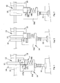
- Fig. 1 shows schematically, an arrangement at a cylinder in an internal combustion engine.
- the engine comprises six cylinders arranged essentially along a straight line.
- the cylinders could be provided with ignition means in each cylinder, e.g. in the form of one or more sparkplugs, or the engine could be adapted for compression ignition.
- At each cylinder one, two or more intake valves, and also one, two or more exhaust valves are provided.
- fig. 1 only one valve 11 is shown.
- the valve 11 is adapted to be actuated by a valve actuation arrangement 12 including a camshaft 13.
- Fig. 1 shows a part of the valve actuation arrangement 12 and the valve 11 in positions at which the valve is not lifted.
- valves in each cylinder are actuated by a camshaft, but it is also possible that only one or some of the valves are camshaft driven, and others actuated in other ways, e.g. electromagnetically. It is also possible that two or more camshafts are used, each for different valves in each cylinder and/or valves in different cylinders.
- the valve actuation arrangement 12 includes cam lobes 14, 15 on the camshaft 13 and tappets 16 at each valve 11, arranged between the camshaft 13 and the valves 11 and each adapted to transfer movements from the camshaft to the respective valve 11. It is also possible that one, some or all of the tappets 16 are adapted to transfer movements to more than one valve each.
- the engine is adapted to run selectively in two valve lift modes, differing regarding the valve lift characteristics influencing the duration of and/or the distance of the valve motion, i.e. the lift.
- the invention is also applicable to engines adapted to run in more than two valve lift modes.
- the valve actuation arrangement 12 includes actuation adjustment mechanisms 17, each arranged at a tappet 16, described closer below. Each actuation adjustment mechanism 17 is adapted to adjust the respective tappet 16 so as to effect shifts from one valve lift mode to another.
- the engine can be adapted to run in different operation modes.
- the latter can include stroke modes, such as a four stroke mode or an eight stroke mode.
- an eight stroke mode can be achieved with cylinder deactivation, as is known in the art.
- the invention is also applicable to engines where all valves are actuated independently of the crankshaft.
- the valve actuation arrangement can include devices for electromagnetic actuation of the valves. Even if the valves are actuated independently of the crankshaft, the valve actuation arrangement can include actuation adjustment mechanisms for shifting between different valve lift modes.
- many different engine operation modes in the form of stroke modes can be achieved, e.g. two, four, six, eight, twelve or sixteen stroke mode.
- Fig. 1 shows schematically a valve 11 and a part of the valve actuation arrangement 12 in positions at which the valve is not lifted.
- the valve actuation arrangement 12 includes for each valve a first cam lobe, herein referred to as a low lift cam lobe 14, and a second cam lobe, herein referred to as a high lift cam lobe 15, on the camshaft 13.
- the high lift cam lobe 15 has a larger eccentric than the low lift cam lobe 14.
- the high lift cam lobe 15 can also, or alternatively, have a different profile than the low lift cam lobe 14 so as to provide for different valve lift characteristics during parts or the whole lifting process, and also a different duration and/or timing of lifting process.
- the tappet 16 comprises two parts, a main part 16a and an additional part, herein referred to as a high lift part 16b, whereby the high lift part 16b is movable in relation to the main part 16a in direction perpendicular to the camshaft 13, and biased towards the camshaft by means of a spring 16c.
- the actuation adjustment mechanism 17 can assume a first position in which a first valve lift mode, in this example also called a low lift mode, can be effected.
- the actuation adjustment mechanism 17 includes a locking device comprising a locking pin 17a. In the first position of the actuation adjustment mechanism 17 the locking pin 17a is located in a first space 17b, with a delimitation having an elongated shape, in the high lift part 16b. Thereby, the locking device is in an unlocked position.
- Fig. 2 shows schematically the valve 11 and a part of the valve actuation arrangement 12 at maximum lift of the valve 11 in the low lift mode.
- the low lift cam lobe 14 pushes the tappet 16 and the valve 11, at which the high lift cam lobe 15 pushes the high lift part 16b along the main part 16a, without acting on the valve 11.
- the locking pin 17a can be moved into a second space 17c in the main part 16a with hydraulic pressure provided through an oil gallery 18 of a mechanism control system, a part of which is shown in fig. 1 and which communicates, at least when the valve is not lifted, with the first space 17b.
- a mechanism control system a part of which is shown in fig. 1 and which communicates, at least when the valve is not lifted, with the first space 17b.
- the locking pin is moved by hydraulic pressure, provided through the oil gallery 18, partly into the second space 17c, for the actuation adjustment mechanism 17 to assume a second position, here a locking position. Thereby, the high lift part 16b is locked to the main part 16a.
- a spring 17d provides for moving the locking pin 17a out of the second space 17c when the hydraulic pressure is released. Thereby, a shift from the high lift to the low lift mode is possible.
- the locking pin can be moved out of the second space 17c by hydraulic pressure in an additional oil gallery that communicates with the second space 17c.
- Fig. 3 shows schematically the valve 11 and a part of the valve actuation arrangement 12 at maximum lift of the valve 11 in the high lift mode.
- the high lift cam lobe 15 acts on the valve 11 via the high lift part 16b, the locking pin 17a, and the main part 16a.
- the valve actuation arrangement in fig. 1, 2 and 3 corresponds schematically to a CPS (Cam Profile Shifting) system.
- valve mode shifts have to be effected during crank shaft angle intervals between the valve lift processes, or at least between critical stages of the valve lift processes.
- a critical stage is when different parts, i.e. referring to fig. 1 the main part 16a and the high lift part 16b, of each actuation adjustment mechanism start moving in relation to each other.
- a critical stage including safety margins is approximately 10 CA (crankshaft angle degrees).
- the duration of the critical stage can vary depending on the type of actuation adjustment mechanism used, or the tolerances in the valve train.
- the windows for valve lift mode shifts can be larger.
- the cylinders being denoted 1, 2, 3, 4, 5, 6, corresponding to their relative spatial position, one set comprises cylinders 1, 2 and 3, and another set comprises cylinders 4, 5 and 6, and also that the ignition sequence of the engine is 1-5-3-6-2-4.
- a four stroke operation mode of the engine there is in each set, at least on average, 240 CA between initiations of the valve lift processes, which leaves windows of 230 CA for mode switch operations, if critical stages of the valve lift processes are taken into account.
- Fig. 4 shows a schematic view of a part of the internal combustion engine according to one embodiment of the invention, and including the arrangement shown in fig. 1, 2, and 3.
- the six cylinders 1, 2, 3, 4, 5, 6 are arranged essentially along a straight line.
- a hydraulic system includes a first sub system 22, herein also referred to as a first mechanism control system 22, and a second sub system 23, herein also referred to as a second mechanism control system 23, both adapted to be pressurized by a common hydraulic pump 24.
- the first mechanism control system 22 and the second mechanism control system 23 could be respective parts of two separate hydraulic systems.
- each actuation adjustment mechanism 17 could be electromagnetic arrangements, whereby the first and the second mechanism control system 22, 23 could be provided as electric systems.
- Each mechanism control system 22, 23 communicates with the actuation adjustment mechanisms 17 at a respective set of the cylinders.
- the first mechanism control system 22 and the second mechanism control system 23 includes a first 25 and a second control valve 26, respectively, to control the pressure in the oil galleries 18.
- the first and second control valves 25, 26 are solenoid valves controllable through signals from a control system of the engine.
- the sets of cylinders are arranged in view of the ignition sequence of the engine.
- the ignition sequence of the engine in a four stroke mode is 1-5-3-6-2-4, which is a standard sequence for inline six cylinder engines.
- a first set of cylinders, controllable through the first mechanism control system 22, includes two cylinders 1, 2 closest to a first end of the row of cylinders, and the fourth cylinder 4 in relation to the first end of the row of cylinders.
- a second set of cylinders, controllable through the second mechanism control system 23 includes two cylinders 5, 6 closest to a second end of the row of cylinders, and the third cylinder 3 in relation to the first end of the row of cylinders.
- first set of cylinders 1, 2, 4 is adapted so that each ignition in a cylinder of the first set 1, 2, 4 is preceded and/or followed by an ignition in a cylinder of the first set 1, 2, 4, without any intermediate ignition in the second set of cylinders.
- second set of cylinders 3, 5, 6 is adapted so that each ignition in a cylinder of the second set 3, 5, 6 is preceded and/or followed by an ignition in a cylinder of the second set 3, 5, 6, without any intermediate ignition in the first set of cylinders.
- each set of cylinders consists of cylinders which are consecutive in a firing sequence.
- At least one cylinder of the second set of cylinders is positioned between two cylinders of the first set of cylinders, and at least one cylinder of the first set of cylinders is positioned between two cylinders of the second set of cylinders.
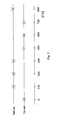
- fig. 5 shows a diagram of valve lift processes in the engine partly depicted in fig. 4.
- the diagram shows critical stages of the valve lift processes in actuation adjustment mechanisms of each set of cylinders, indicated with the cylinder number at respective crankshaft angles.
- trigger window of approximately 470 CA if a duration of 10 CA is assumed.
- this can be effected by activating the first mechanism control system 22 during an interval between critical stages at the first and the second cylinder 1, 2, and activating the second mechanism control system 23 during an interval between critical stages at the sixth and the fifth cylinder 6, 5.
- the large windows in the CA domain for effecting valve lift mode shifts drastically reduces risks of triggering a mode shift at the wrong moment. This will reduce risks of damages occurring in the engine, specially in the valve trains, due to a mode shift being effected during a critical stage of the valve lifting process.
- the large windows achieved will also increase considerably the predictability for each cylinder of the cycle in which the mode shift will be effected. This will substantially reduce the risk of a mode shift being effected in a cycle different to the predicted cycle, which could result in a lack of coordination between the valve lift and other parameters, such as the amount of air to be inducted, which in turn could result in a misfire.
- the large windows achieved by the invention allows for relatively low tolerances and relatively large inaccuracies in the action of the mode shift arrangement, which can simplify the design thereof and lower production costs.
- Fig. 6 shows a schematic view of a part of the internal combustion engine according to an alternative embodiment of the invention, and including the arrangement shown in fig. 1, 2, and 3.
- a hydraulic system As in the example described with reference to fig. 4, here there are six cylinders 1, 2, 3, 4, 5, 6 are arranged essentially along a straight line, a hydraulic system, with a first mechanism control system 22 and a second mechanism control system 23 both adapted to be pressurized by a common hydraulic pump 24.
- each mechanism control system 22, 23 communicates with the actuation adjustment mechanisms 17 at a respective set of the cylinders, and the first mechanism control system 22 and the second mechanism control system 23 includes a first 25 and a second control valve 26, respectively.
- the ignition sequence of the engine is the same as above, i.e. 1-5-3-6-2-4.
- a first set of cylinders, controllable through the first mechanism control system 22, includes the first, third and fifth cylinder 1, 3, 5 in relation to a first end of the row of cylinders.
- a second set of cylinders, controllable through the second mechanism control system 23, includes the second, fourth and sixth cylinder 2, 4, 6 in relation to the first end of the row of cylinders.
- the first set of cylinders 1, 3, 5 is adapted so that each ignition in a cylinder of the first set 1, 3, 5 is preceded and/or followed by an ignition in a cylinder of the first set 1, 3, 5, without any intermediate ignition in the second set of cylinders.
- each set of cylinders 2, 4, 6 is adapted so that each ignition in a cylinder of the second set 2, 4, 6 is preceded and/or followed by an ignition in a cylinder of the second set 2, 4, 6, without any intermediate ignition in the first set of cylinders.
- each set of cylinders consists of cylinders which are consecutive in a firing sequence.
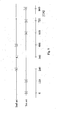
- Fig. 7 shows a diagram of valve lift processes in the engine partly depicted in fig. 6.
- the diagram shows critical stages of the valve lift processes, similarly to fig. 5 referred to above.
- this can be effected by activating the first mechanism control system 22 during an interval between critical stages at the third and the first cylinder 3, 1, and activating the second mechanism control system 23 during an interval between critical stages at the fourth and the sixth cylinder 4, 6.
- Fig. 8 shows a schematic view of a part of the internal combustion engine according to a further embodiment of the invention, and including the arrangement shown in fig. 1, 2, and 3.
- a first set of cylinders, controllable through a first mechanism control system 22 includes the first, fourth and fifth cylinder 1, 4, 5 in relation to a first end of the row of cylinders.
- a second set of cylinders, controllable through a second mechanism control system 23 includes the second, third and sixth cylinder 2, 3, 6 in relation to the first end of the row of cylinders.
- ignitions in each set of cylinders are consecutive.
- Fig. 9 shows a diagram of valve lift processes in the engine partly depicted in fig. 8.
- the diagram shows critical stages of the valve lift processes, similarly to fig. 5 and 7 referred to above.
- a window of approximately 470 CA if a duration of 10 CA is assumed, and if a valve lift mode shift is requested, this can be effected by activating the first mechanism control system 22 during an interval between critical stages at the fifth and the fourth cylinder 5, 4, and activating the second mechanism control system 23 during an interval between critical stages at the second and the third cylinder 2, 3.
- the invention is applicable to engines with other types of actuation adjustment mechanisms than the type described above.
- the invention could be used in combination with actuation adjustment mechanisms without a locking device, such as the one described in the patent document US5113813.
- actuation adjustment mechanisms without a locking device, such as the one described in the patent document US5113813.
- the invention is specially suited for a predefined ignition sequence, and since the ignition sequence can change if the engine operation mode is changed, the arrangement according to invention can be specially adapted for a certain engine operation mode.
- the invention has been described with reference to an engine operation mode of four stroke cycles, but it could also be adapted to other stroke modes, such as six, eight or twelve stroke modes, where ignition sequences could differ from the four stroke mode.
- the engine described is an inline six cylinder engine.
- the invention is also applicable to engine with different configurations.
- it can be used in a V-8 engine, with the ignition sequence 1-5-4-8-6-3-7-2.
- the invention can be used, at which each bank of the engine corresponds to an inline six cylinder engine. This means that the invention can be applied as described above to each bank of a V-12 engine.
Landscapes
- Engineering & Computer Science (AREA)
- Mechanical Engineering (AREA)
- General Engineering & Computer Science (AREA)
- Chemical & Material Sciences (AREA)
- Combustion & Propulsion (AREA)
- Valve Device For Special Equipments (AREA)
- Output Control And Ontrol Of Special Type Engine (AREA)
Abstract
Description
- The present invention relates to an internal combustion engine provided with a valve control mechanism.
- In known art of internal combustion engines a number of designs have been suggested for accomplishing valve drives, for inlet and/or exhaust valves, than can shift between different valve lift modes, at which the valve lift curves differ from each other. Shifts between said modes are usually accomplished through mechanical arrangements at the valve tappets.
- There must be a high degree of certainty that shifts between the valve modes are not effected during certain critical stages of the valve lift operation. A reason for this is to avoid risks of damages occurring in the engine. Another reason is that it has to be possible to predict for each cylinder the cycle in which the mode shift is effected. If a mode shift is effected in a cycle different to the predicted cycle, there could be a lack of coordination between the valve lift and other parameters, such as the amount of air to be inducted, which in turn could result in a misfire. Therefore, it has to be made certain that mode shifts are effected in certain trigger windows between each valve lift process of the engine. These windows are usually relatively small, and at high engine speeds their time duration can be very small, increasing the risk, due to inaccuracy of the system, of a mode shift being effected at a critical stage of the valve train or in a cycle not predicted.
- It is an object of the present invention to reduce the risk of damages of an internal combustion engine adapted to run selectively in different modes regarding the lift characteristics of valves of the engine.
- It is also an object of the invention to secure a smooth operation of the engine and decrease the risk of discomfort for the driver and passengers of a vehicle due to disturbances in the engine operation.
- These objects are reached with an internal combustion engine with a plurality of cylinders, at least one valve at each cylinder being adapted to be actuated by a valve actuation arrangement, the valve actuation arrangement comprising at least two actuation adjustment mechanisms, each adapted to assume a first position whereby at least one of the valves can be actuated according to a first valve lift mode, and to assume a second position whereby at least one of the valves can be actuated according to a second valve lift mode, the position of at least one actuation adjustment mechanism for at least one valve at a first set of cylinders being controllable through a first mechanism control system. The position of at least one actuation adjustment mechanism for at least one valve at a second set of cylinders is controllable through a second mechanism control system, whereby the first set of cylinders consists of cylinders which are consecutive in a firing sequence, during operation of the engine according to at least one engine operation mode.
- Since separate control systems for the actuation adjustment mechanisms are provided for separate sets of cylinders, and a set of cylinders is correlated with the firing or ignition sequence of the engine so that ignition takes place consecutively in the set of cylinders, there are large trigger windows provided for activating the actuation adjustment mechanisms at one set of cylinders while ignitions are taking place in another set of cylinders.
- Below the invention will be described closer with the aid of the drawing, in which
- fig. 1, 2 and 3 show schematically, an arrangement at a cylinder in an internal combustion engine,
- fig. 4 shows a schematic view of a part of an internal combustion engine according to one embodiment of the invention,
- fig. 5 shows a diagram showing critical stages of the valve lift processes of the engine from fig. 4,
- fig. 6 shows a schematic view of a part of an internal combustion engine according to another embodiment of the invention,
- fig. 7 shows a diagram showing critical stages of the valve lift processes of the engine from fig. 6,
- fig. 8 shows a schematic view of a part of an internal combustion engine according a further embodiment of the invention, and
- fig. 9 shows a diagram showing critical stages of the valve lift processes of the engine from fig. 8.
- Fig. 1 shows schematically, an arrangement at a cylinder in an internal combustion engine. The engine comprises six cylinders arranged essentially along a straight line. The cylinders could be provided with ignition means in each cylinder, e.g. in the form of one or more sparkplugs, or the engine could be adapted for compression ignition. At each cylinder one, two or more intake valves, and also one, two or more exhaust valves are provided. For simplicity of this presentation, in fig. 1 only one
valve 11 is shown. Thevalve 11 is adapted to be actuated by avalve actuation arrangement 12 including acamshaft 13. Fig. 1 shows a part of thevalve actuation arrangement 12 and thevalve 11 in positions at which the valve is not lifted. Here it is assumed that all valves in each cylinder are actuated by a camshaft, but it is also possible that only one or some of the valves are camshaft driven, and others actuated in other ways, e.g. electromagnetically. It is also possible that two or more camshafts are used, each for different valves in each cylinder and/or valves in different cylinders. - The
valve actuation arrangement 12 includescam lobes camshaft 13 andtappets 16 at eachvalve 11, arranged between thecamshaft 13 and thevalves 11 and each adapted to transfer movements from the camshaft to therespective valve 11. It is also possible that one, some or all of thetappets 16 are adapted to transfer movements to more than one valve each. - The engine is adapted to run selectively in two valve lift modes, differing regarding the valve lift characteristics influencing the duration of and/or the distance of the valve motion, i.e. the lift. The invention is also applicable to engines adapted to run in more than two valve lift modes. The
valve actuation arrangement 12 includesactuation adjustment mechanisms 17, each arranged at atappet 16, described closer below. Eachactuation adjustment mechanism 17 is adapted to adjust therespective tappet 16 so as to effect shifts from one valve lift mode to another. - In addition to different valve lift modes, the engine can be adapted to run in different operation modes. The latter can include stroke modes, such as a four stroke mode or an eight stroke mode. In an engine with camshaft actuated valves, an eight stroke mode can be achieved with cylinder deactivation, as is known in the art. The invention is also applicable to engines where all valves are actuated independently of the crankshaft. As an example, the valve actuation arrangement can include devices for electromagnetic actuation of the valves. Even if the valves are actuated independently of the crankshaft, the valve actuation arrangement can include actuation adjustment mechanisms for shifting between different valve lift modes. In an engine where the valves are actuated independently of the crankshaft, many different engine operation modes in the form of stroke modes can be achieved, e.g. two, four, six, eight, twelve or sixteen stroke mode.
- Fig. 1 shows schematically a
valve 11 and a part of thevalve actuation arrangement 12 in positions at which the valve is not lifted. Thevalve actuation arrangement 12 includes for each valve a first cam lobe, herein referred to as a lowlift cam lobe 14, and a second cam lobe, herein referred to as a highlift cam lobe 15, on thecamshaft 13. The highlift cam lobe 15 has a larger eccentric than the lowlift cam lobe 14. The highlift cam lobe 15 can also, or alternatively, have a different profile than the lowlift cam lobe 14 so as to provide for different valve lift characteristics during parts or the whole lifting process, and also a different duration and/or timing of lifting process. - The
tappet 16 comprises two parts, amain part 16a and an additional part, herein referred to as ahigh lift part 16b, whereby thehigh lift part 16b is movable in relation to themain part 16a in direction perpendicular to thecamshaft 13, and biased towards the camshaft by means of aspring 16c. Theactuation adjustment mechanism 17 can assume a first position in which a first valve lift mode, in this example also called a low lift mode, can be effected. Theactuation adjustment mechanism 17 includes a locking device comprising alocking pin 17a. In the first position of theactuation adjustment mechanism 17 thelocking pin 17a is located in afirst space 17b, with a delimitation having an elongated shape, in thehigh lift part 16b. Thereby, the locking device is in an unlocked position. - Fig. 2 shows schematically the
valve 11 and a part of thevalve actuation arrangement 12 at maximum lift of thevalve 11 in the low lift mode. The lowlift cam lobe 14 pushes thetappet 16 and thevalve 11, at which the highlift cam lobe 15 pushes thehigh lift part 16b along themain part 16a, without acting on thevalve 11. - Referring to fig. 1, the
locking pin 17a can be moved into asecond space 17c in themain part 16a with hydraulic pressure provided through anoil gallery 18 of a mechanism control system, a part of which is shown in fig. 1 and which communicates, at least when the valve is not lifted, with thefirst space 17b. To shift from the first valve lift mode to a second valve lift mode, in this example referred to as high lift mode, the locking pin is moved by hydraulic pressure, provided through theoil gallery 18, partly into thesecond space 17c, for theactuation adjustment mechanism 17 to assume a second position, here a locking position. Thereby, thehigh lift part 16b is locked to themain part 16a. - A
spring 17d provides for moving thelocking pin 17a out of thesecond space 17c when the hydraulic pressure is released. Thereby, a shift from the high lift to the low lift mode is possible. Alternatively, the locking pin can be moved out of thesecond space 17c by hydraulic pressure in an additional oil gallery that communicates with thesecond space 17c. - Fig. 3 shows schematically the
valve 11 and a part of thevalve actuation arrangement 12 at maximum lift of thevalve 11 in the high lift mode. The highlift cam lobe 15 acts on thevalve 11 via thehigh lift part 16b, the lockingpin 17a, and themain part 16a. The valve actuation arrangement in fig. 1, 2 and 3 corresponds schematically to a CPS (Cam Profile Shifting) system. - As can be understood from the above, a shift of valve modes can not be effectuated when the valve is in the process of lifting, since parts of the
actuation adjustment mechanism 17, i.e. the lockingpin 17a, thefirst space 17b, and thesecond space 17c, have to be positioned properly in relation to each other for the locking pin to move in or out of the locking position. Also, if a shift from the low to the high lift mode is attempted during the initial phase of the lifting process of a valve, referring to fig. 1, the relative movement between themain part 16a and thehigh lift part 16b and the simultaneous movement of thelocking pin 17a towards thesecond space 17c could result in excessive wear or damages of certain parts. This problem is present in all valve actuation arrangements, where shifting between different valve lift modes are effected by means of locking mechanisms, different parts of which move in relation to each other during valve lift processes. - Thus, the valve mode shifts have to be effected during crank shaft angle intervals between the valve lift processes, or at least between critical stages of the valve lift processes. In the example above such a critical stage is when different parts, i.e. referring to fig. 1 the
main part 16a and thehigh lift part 16b, of each actuation adjustment mechanism start moving in relation to each other. Typically, in CPS system such a critical stage including safety margins is approximately 10 CA (crankshaft angle degrees). However, the duration of the critical stage can vary depending on the type of actuation adjustment mechanism used, or the tolerances in the valve train. In a four stroke operation mode of a six cylinder engine there is, at least on average, 120 CA between each intake valve actuation or each exhaust valve actuation. Then, if theoil gallery 18, (fig. 1), communicates with actuation adjustment mechanisms of all cylinders, there are windows of approximately 110 CA in which mode shifts can be carried out. This is a relatively small interval which put high demands on accuracy of any control system for the actuation adjustment mechanisms. - If there are two parts of a hydraulic system, or two hydraulic systems, that can be controlled separately and each of which communicates through respective oil galleries with actuation adjustment mechanisms of a separate set of cylinders, the windows for valve lift mode shifts can be larger. We assume that in an inline six cylinder engine, the cylinders being denoted 1, 2, 3, 4, 5, 6, corresponding to their relative spatial position, one set comprises
cylinders cylinders - Fig. 4 shows a schematic view of a part of the internal combustion engine according to one embodiment of the invention, and including the arrangement shown in fig. 1, 2, and 3. As mentioned, the six
cylinders first sub system 22, herein also referred to as a firstmechanism control system 22, and asecond sub system 23, herein also referred to as a secondmechanism control system 23, both adapted to be pressurized by a commonhydraulic pump 24. Alternatively, the firstmechanism control system 22 and the secondmechanism control system 23, could be respective parts of two separate hydraulic systems. - As an alternative, each
actuation adjustment mechanism 17 could be electromagnetic arrangements, whereby the first and the secondmechanism control system - Each
mechanism control system actuation adjustment mechanisms 17 at a respective set of the cylinders. The firstmechanism control system 22 and the secondmechanism control system 23 includes a first 25 and asecond control valve 26, respectively, to control the pressure in theoil galleries 18. Suitably, the first andsecond control valves - According to the invention, the sets of cylinders are arranged in view of the ignition sequence of the engine. In this example the ignition sequence of the engine in a four stroke mode is 1-5-3-6-2-4, which is a standard sequence for inline six cylinder engines. A first set of cylinders, controllable through the first
mechanism control system 22, includes twocylinders 1, 2 closest to a first end of the row of cylinders, and thefourth cylinder 4 in relation to the first end of the row of cylinders. A second set of cylinders, controllable through the secondmechanism control system 23, includes twocylinders 5, 6 closest to a second end of the row of cylinders, and thethird cylinder 3 in relation to the first end of the row of cylinders. This means that the first set ofcylinders first set first set cylinders second set second set - To clarify the advantage of the invention, fig. 5 shows a diagram of valve lift processes in the engine partly depicted in fig. 4. The diagram shows critical stages of the valve lift processes in actuation adjustment mechanisms of each set of cylinders, indicated with the cylinder number at respective crankshaft angles. It can be seen that in each four stroke cycle and for each set of cylinders there is one large window, also called trigger window, of approximately 470 CA if a duration of 10 CA is assumed. Thereby, if a valve lift mode shift is requested, this can be effected by activating the first
mechanism control system 22 during an interval between critical stages at the first and thesecond cylinder 1, 2, and activating the secondmechanism control system 23 during an interval between critical stages at the sixth and thefifth cylinder 6, 5. - The large windows in the CA domain for effecting valve lift mode shifts, achieved by the invention, drastically reduces risks of triggering a mode shift at the wrong moment. This will reduce risks of damages occurring in the engine, specially in the valve trains, due to a mode shift being effected during a critical stage of the valve lifting process. The large windows achieved will also increase considerably the predictability for each cylinder of the cycle in which the mode shift will be effected. This will substantially reduce the risk of a mode shift being effected in a cycle different to the predicted cycle, which could result in a lack of coordination between the valve lift and other parameters, such as the amount of air to be inducted, which in turn could result in a misfire. The large windows achieved by the invention allows for relatively low tolerances and relatively large inaccuracies in the action of the mode shift arrangement, which can simplify the design thereof and lower production costs.
- Fig. 6 shows a schematic view of a part of the internal combustion engine according to an alternative embodiment of the invention, and including the arrangement shown in fig. 1, 2, and 3. As in the example described with reference to fig. 4, here there are six
cylinders mechanism control system 22 and a secondmechanism control system 23 both adapted to be pressurized by a commonhydraulic pump 24. As described above, eachmechanism control system actuation adjustment mechanisms 17 at a respective set of the cylinders, and the firstmechanism control system 22 and the secondmechanism control system 23 includes a first 25 and asecond control valve 26, respectively. - The ignition sequence of the engine is the same as above, i.e. 1-5-3-6-2-4. Differing from the example above, here a first set of cylinders, controllable through the first
mechanism control system 22, includes the first, third andfifth cylinder mechanism control system 23, includes the second, fourth andsixth cylinder cylinders first set first set cylinders second set second set - Fig. 7 shows a diagram of valve lift processes in the engine partly depicted in fig. 6. The diagram shows critical stages of the valve lift processes, similarly to fig. 5 referred to above. In each four stroke cycle and for each set of cylinders there is one large window of approximately 470 CA if a duration of 10 CA is assumed. Thereby, if a valve lift mode shift is requested, this can be effected by activating the first
mechanism control system 22 during an interval between critical stages at the third and thefirst cylinder mechanism control system 23 during an interval between critical stages at the fourth and thesixth cylinder - Fig. 8 shows a schematic view of a part of the internal combustion engine according to a further embodiment of the invention, and including the arrangement shown in fig. 1, 2, and 3. Differing from the embodiments shown in fig. 4 and 6, a first set of cylinders, controllable through a first
mechanism control system 22, includes the first, fourth andfifth cylinder mechanism control system 23, includes the second, third andsixth cylinder - Fig. 9 shows a diagram of valve lift processes in the engine partly depicted in fig. 8. The diagram shows critical stages of the valve lift processes, similarly to fig. 5 and 7 referred to above. In each four stroke cycle and for each set of cylinders there is a window of approximately 470 CA if a duration of 10 CA is assumed, and if a valve lift mode shift is requested, this can be effected by activating the first
mechanism control system 22 during an interval between critical stages at the fifth and thefourth cylinder 5, 4, and activating the secondmechanism control system 23 during an interval between critical stages at the second and thethird cylinder 2, 3. - It should be pointed out that the embodiment described above with reference to fig. 4 has special merits in that, in comparison to e.g. the embodiment described with reference to fig. 6, it provides for shorter channels in the engine block for the
oil galleries 18. Also, it contains less intersections of conduits ofseparate oil galleries 18, which is an advantage, since these intersections present problems in the design and manufacturing of the engine. Thus, this embodiment will result in a relatively simple design and relatively low manufacturing costs. - It should be pointed out that the invention is applicable to engines with other types of actuation adjustment mechanisms than the type described above. For example, the invention could be used in combination with actuation adjustment mechanisms without a locking device, such as the one described in the patent document US5113813. The merit described above, that the risk of valve mode shifts being effected in stroke cycles other than the ones intended, is present no matter what type of actuation adjustment mechanisms is used for shifting the valve actuation.
- From the above, it can be understood that the invention is specially suited for a predefined ignition sequence, and since the ignition sequence can change if the engine operation mode is changed, the arrangement according to invention can be specially adapted for a certain engine operation mode. Above, the invention has been described with reference to an engine operation mode of four stroke cycles, but it could also be adapted to other stroke modes, such as six, eight or twelve stroke modes, where ignition sequences could differ from the four stroke mode.
- Above, the engine described is an inline six cylinder engine. However, the invention is also applicable to engine with different configurations. For example, it can be used in a V-8 engine, with the ignition sequence 1-5-4-8-6-3-7-2. Also, in a V-12 engine the invention can be used, at which each bank of the engine corresponds to an inline six cylinder engine. This means that the invention can be applied as described above to each bank of a V-12 engine.
Claims (7)
- An internal combustion engine with a plurality of cylinders,at least one valve (11) at each cylinder being adapted to be actuated by a valve actuation arrangement (12),the valve actuation arrangement (12) comprising at least two actuation adjustment mechanisms (17), each adapted to assume a first position whereby at least one of the valves can be actuated according to a first valve lift mode, and to assume a second position whereby at least one of the valves can be actuated according to a second valve lift mode,the position of at least one actuation adjustment mechanism (17) for at least one valve (11) at a first set of cylinders being controllable through a first mechanism control system (22), characterized in thatthe position of at least one actuation adjustment mechanism (17) for at least one valve (11) at a second set of cylinders is controllable through a second mechanism control system (23),whereby the first set of cylinders consists of cylinders which are consecutive in a firing sequence, during operation of the engine according to at least one engine operation mode.
- An internal combustion engine according to claim 1, whereby the cylinders are arranged essentially along at least one line, whereby, at at least one of the lines, at least one cylinder of the second set of cylinders is positioned between two cylinders of the first set of cylinders.
- An internal combustion engine according to claim 2, whereby, at least at said line in which at least one cylinder of the second set of cylinders is positioned between two cylinders of the first set of cylinders, at least one cylinder of the first set of cylinders is positioned between two cylinders of the second set of cylinders.
- An internal combustion engine according to any of the preceding claims, whereby one actuation adjustment mechanism (17) is provided for each valve (11) that can be actuated according to a first or a second valve lift mode.
- An internal combustion engine according to any of the preceding claims, comprising six cylinders arranged essentially along a straight line.
- An internal combustion engine according to any of the preceding claims, whereby the actuation adjustment mechanism (17) includes a locking device, and the first and the second position correspond to an unlocked and a locked position, respectively, of the locking device.
- An internal combustion engine according to claim 6, whereby the valve actuation arrangement (12) comprises a main part (16a) and an additional part (16b), whereby, in the unlocked position of the actuation adjustment mechanism (17), the additional part (16b) is movable in relation to the main part (16a), whereby the at least one valve (11) can be actuated by a first cam lobe (14) via the main part (16a), and whereby, in the locked position of the actuation adjustment mechanism (17), the additional part (16b) is secured to the main part (16a), whereby the at least one valve (11) can be actuated by a second cam lobe (15) via the additional part (16b).
Priority Applications (3)
| Application Number | Priority Date | Filing Date | Title |
|---|---|---|---|
| EP03003568A EP1447547B1 (en) | 2003-02-17 | 2003-02-17 | An internal combustion engine having a valve travel changing device |
| DE60304671T DE60304671T2 (en) | 2003-02-17 | 2003-02-17 | Internal combustion engine with valve lift switching device |
| US10/779,409 US6848403B2 (en) | 2003-02-17 | 2004-02-13 | Internal combustion engine |
Applications Claiming Priority (1)
| Application Number | Priority Date | Filing Date | Title |
|---|---|---|---|
| EP03003568A EP1447547B1 (en) | 2003-02-17 | 2003-02-17 | An internal combustion engine having a valve travel changing device |
Publications (2)
| Publication Number | Publication Date |
|---|---|
| EP1447547A1 true EP1447547A1 (en) | 2004-08-18 |
| EP1447547B1 EP1447547B1 (en) | 2006-04-19 |
Family
ID=32668998
Family Applications (1)
| Application Number | Title | Priority Date | Filing Date |
|---|---|---|---|
| EP03003568A Expired - Lifetime EP1447547B1 (en) | 2003-02-17 | 2003-02-17 | An internal combustion engine having a valve travel changing device |
Country Status (3)
| Country | Link |
|---|---|
| US (1) | US6848403B2 (en) |
| EP (1) | EP1447547B1 (en) |
| DE (1) | DE60304671T2 (en) |
Cited By (1)
| Publication number | Priority date | Publication date | Assignee | Title |
|---|---|---|---|---|
| DE102010056403B4 (en) * | 2010-01-05 | 2021-06-24 | GM Global Technology Operations LLC (n. d. Ges. d. Staates Delaware) | Systems and methods for controlling variable valve lift |
Families Citing this family (4)
| Publication number | Priority date | Publication date | Assignee | Title |
|---|---|---|---|---|
| GB2415744B (en) * | 2004-05-13 | 2008-10-29 | Anthony Edgar Blackburn | Engine cycles |
| US7284514B2 (en) * | 2006-02-13 | 2007-10-23 | Ford Global Technologies, Llc | Engine control system |
| EP1873377B1 (en) * | 2006-06-28 | 2010-03-17 | Ford Global Technologies, LLC | An internal combustion engine comprising a variable valve lift profile system and a method for controlling valve lift profile shifting |
| US7277789B1 (en) | 2006-07-06 | 2007-10-02 | Ford Global Technologies, Llc | System for transmitting signals between an engine control unit and a valve control unit |
Citations (5)
| Publication number | Priority date | Publication date | Assignee | Title |
|---|---|---|---|---|
| US5603293A (en) * | 1994-12-15 | 1997-02-18 | Dr. Ing. H.C.F. Porsche Ag | Tappet for a switchable valve of an internal combustion engine |
| EP0779411A1 (en) * | 1995-12-13 | 1997-06-18 | Dr.Ing. h.c. F. Porsche Aktiengesellschaft | Valve driving device for an internal combustion engine |
| DE19632651A1 (en) * | 1996-08-13 | 1998-02-19 | Siemens Ag | IC engine control arrangement for cylinder deactivation |
| US5950583A (en) * | 1997-04-25 | 1999-09-14 | Dr. Ing. H.C.F. Porsche Ag | Valve gear of an internal-combustion engine |
| US6332445B1 (en) * | 1998-08-17 | 2001-12-25 | Dr. Ing. H.C.F. Porsche Ag | Method for operating and valve drive for a multicylinder internal combustion engine |
Family Cites Families (1)
| Publication number | Priority date | Publication date | Assignee | Title |
|---|---|---|---|---|
| US6474278B1 (en) * | 2000-11-20 | 2002-11-05 | General Motors Corporation | Global cam sensing system |
-
2003
- 2003-02-17 EP EP03003568A patent/EP1447547B1/en not_active Expired - Lifetime
- 2003-02-17 DE DE60304671T patent/DE60304671T2/en not_active Expired - Lifetime
-
2004
- 2004-02-13 US US10/779,409 patent/US6848403B2/en not_active Expired - Lifetime
Patent Citations (5)
| Publication number | Priority date | Publication date | Assignee | Title |
|---|---|---|---|---|
| US5603293A (en) * | 1994-12-15 | 1997-02-18 | Dr. Ing. H.C.F. Porsche Ag | Tappet for a switchable valve of an internal combustion engine |
| EP0779411A1 (en) * | 1995-12-13 | 1997-06-18 | Dr.Ing. h.c. F. Porsche Aktiengesellschaft | Valve driving device for an internal combustion engine |
| DE19632651A1 (en) * | 1996-08-13 | 1998-02-19 | Siemens Ag | IC engine control arrangement for cylinder deactivation |
| US5950583A (en) * | 1997-04-25 | 1999-09-14 | Dr. Ing. H.C.F. Porsche Ag | Valve gear of an internal-combustion engine |
| US6332445B1 (en) * | 1998-08-17 | 2001-12-25 | Dr. Ing. H.C.F. Porsche Ag | Method for operating and valve drive for a multicylinder internal combustion engine |
Cited By (1)
| Publication number | Priority date | Publication date | Assignee | Title |
|---|---|---|---|---|
| DE102010056403B4 (en) * | 2010-01-05 | 2021-06-24 | GM Global Technology Operations LLC (n. d. Ges. d. Staates Delaware) | Systems and methods for controlling variable valve lift |
Also Published As
| Publication number | Publication date |
|---|---|
| DE60304671D1 (en) | 2006-05-24 |
| US20040159295A1 (en) | 2004-08-19 |
| DE60304671T2 (en) | 2006-09-07 |
| EP1447547B1 (en) | 2006-04-19 |
| US6848403B2 (en) | 2005-02-01 |
Similar Documents
| Publication | Publication Date | Title |
|---|---|---|
| US7404383B2 (en) | Valve train with cam switching for the gas exchange valves of a four-cycle internal combustion engine | |
| EP0515520B1 (en) | Valve control means | |
| US10830159B2 (en) | Valve-actuating device for varying the valve lift | |
| US4651684A (en) | Valve timing control system for internal combustion engine | |
| US5359970A (en) | Valve drive for an internal combustion engine | |
| US7503296B2 (en) | Cylinder deactivation apparatus | |
| KR20130108362A (en) | Four-stroke internal combustion engine comprising an engine brake | |
| EP2530261B1 (en) | Valve apparatus for an internal combustion engine | |
| EP0462568A1 (en) | Timing system, particularly for an internal combustion engine with a number of valves per cylinder | |
| US5560329A (en) | Valvetrain for a pushrod engine | |
| EP1447547B1 (en) | An internal combustion engine having a valve travel changing device | |
| EP1378637B1 (en) | An internal-combustion engine with two inlet valves for each cylinder and an electronically controlled system for actuating the two inlet valves in differentiated and alternating ways | |
| US6832583B2 (en) | Direct acting differential two-step valve train | |
| US20120031361A1 (en) | Internal combustion engine | |
| US20210071594A1 (en) | Multi-Mode Valve Lift | |
| EP1707764A1 (en) | Variable valve operating mechanism for four-stroke internal combustion engine | |
| JP3381311B2 (en) | Variable valve train for internal combustion engine | |
| US5337712A (en) | Valve gear for at least two simultaneously operated valves | |
| US20230332518A1 (en) | Valve-actuating device having a switching device | |
| EP0322572A1 (en) | Valve actuating device for multi valve-type engine | |
| US20020100441A1 (en) | Variable valve control system for internal combustion engine | |
| KR20180058225A (en) | Lost-motion differential valve operation | |
| EP1580407A1 (en) | Method for detection failure in a cam profile switching system | |
| EP0444562A1 (en) | Timing system, particularly for an internal combustion engine with a number of valves per cylinder | |
| JPS59213912A (en) | Operation switching device of valve in internal- combustion engine |
Legal Events
| Date | Code | Title | Description |
|---|---|---|---|
| PUAI | Public reference made under article 153(3) epc to a published international application that has entered the european phase |
Free format text: ORIGINAL CODE: 0009012 |
|
| AK | Designated contracting states |
Kind code of ref document: A1 Designated state(s): AT BE BG CH CY CZ DE DK EE ES FI FR GB GR HU IE IT LI LU MC NL PT SE SI SK TR |
|
| AX | Request for extension of the european patent |
Extension state: AL LT LV MK RO |
|
| 17P | Request for examination filed |
Effective date: 20050211 |
|
| AKX | Designation fees paid |
Designated state(s): DE GB SE |
|
| RBV | Designated contracting states (corrected) |
Designated state(s): DE GB SE |
|
| GRAP | Despatch of communication of intention to grant a patent |
Free format text: ORIGINAL CODE: EPIDOSNIGR1 |
|
| GRAS | Grant fee paid |
Free format text: ORIGINAL CODE: EPIDOSNIGR3 |
|
| GRAA | (expected) grant |
Free format text: ORIGINAL CODE: 0009210 |
|
| RAP1 | Party data changed (applicant data changed or rights of an application transferred) |
Owner name: FORD GLOBAL TECHNOLOGIES, LLC |
|
| AK | Designated contracting states |
Kind code of ref document: B1 Designated state(s): DE GB SE |
|
| REG | Reference to a national code |
Ref country code: GB Ref legal event code: FG4D |
|
| RAP2 | Party data changed (patent owner data changed or rights of a patent transferred) |
Owner name: FORD GLOBAL TECHNOLOGIES, LLC. |
|
| REF | Corresponds to: |
Ref document number: 60304671 Country of ref document: DE Date of ref document: 20060524 Kind code of ref document: P |
|
| REG | Reference to a national code |
Ref country code: SE Ref legal event code: TRGR |
|
| PLBE | No opposition filed within time limit |
Free format text: ORIGINAL CODE: 0009261 |
|
| STAA | Information on the status of an ep patent application or granted ep patent |
Free format text: STATUS: NO OPPOSITION FILED WITHIN TIME LIMIT |
|
| 26N | No opposition filed |
Effective date: 20070122 |
|
| REG | Reference to a national code |
Ref country code: GB Ref legal event code: 732E Free format text: REGISTERED BETWEEN 20111020 AND 20111025 |
|
| REG | Reference to a national code |
Ref country code: DE Ref legal event code: R082 Ref document number: 60304671 Country of ref document: DE Representative=s name: HOFFMANN - EITLE, DE |
|
| REG | Reference to a national code |
Ref country code: DE Ref legal event code: R081 Ref document number: 60304671 Country of ref document: DE Owner name: VOLVO CAR CORPORATION, SE Free format text: FORMER OWNER: FORD GLOBAL TECHNOLOGIES, LLC, DEARBORN, MICH., US Effective date: 20120207 Ref country code: DE Ref legal event code: R082 Ref document number: 60304671 Country of ref document: DE Representative=s name: HOFFMANN - EITLE PATENT- UND RECHTSANWAELTE PA, DE Effective date: 20120207 Ref country code: DE Ref legal event code: R082 Ref document number: 60304671 Country of ref document: DE Representative=s name: HOFFMANN - EITLE, DE Effective date: 20120207 Ref country code: DE Ref legal event code: R081 Ref document number: 60304671 Country of ref document: DE Owner name: VOLVO CAR CORPORATION, SE Free format text: FORMER OWNER: FORD GLOBAL TECHNOLOGIES, LLC, DEARBORN, US Effective date: 20120207 |
|
| PGFP | Annual fee paid to national office [announced via postgrant information from national office to epo] |
Ref country code: SE Payment date: 20150217 Year of fee payment: 13 |
|
| REG | Reference to a national code |
Ref country code: SE Ref legal event code: EUG |
|
| PG25 | Lapsed in a contracting state [announced via postgrant information from national office to epo] |
Ref country code: SE Free format text: LAPSE BECAUSE OF NON-PAYMENT OF DUE FEES Effective date: 20160218 |
|
| PGFP | Annual fee paid to national office [announced via postgrant information from national office to epo] |
Ref country code: CH Payment date: 20190115 Year of fee payment: 18 |
|
| GBPC | Gb: european patent ceased through non-payment of renewal fee |
Effective date: 20200217 |
|
| PG25 | Lapsed in a contracting state [announced via postgrant information from national office to epo] |
Ref country code: GB Free format text: LAPSE BECAUSE OF NON-PAYMENT OF DUE FEES Effective date: 20200217 |
|
| PGFP | Annual fee paid to national office [announced via postgrant information from national office to epo] |
Ref country code: DE Payment date: 20220119 Year of fee payment: 20 |
|
| REG | Reference to a national code |
Ref country code: DE Ref legal event code: R071 Ref document number: 60304671 Country of ref document: DE |