EP1447317A2 - Bicycle front derailleur - Google Patents
Bicycle front derailleur Download PDFInfo
- Publication number
- EP1447317A2 EP1447317A2 EP04003074A EP04003074A EP1447317A2 EP 1447317 A2 EP1447317 A2 EP 1447317A2 EP 04003074 A EP04003074 A EP 04003074A EP 04003074 A EP04003074 A EP 04003074A EP 1447317 A2 EP1447317 A2 EP 1447317A2
- Authority
- EP
- European Patent Office
- Prior art keywords
- coupling portion
- link member
- front derailleur
- bicycle
- pivotally coupled
- Prior art date
- Legal status (The legal status is an assumption and is not a legal conclusion. Google has not performed a legal analysis and makes no representation as to the accuracy of the status listed.)
- Granted
Links
Images


Classifications
-
- B—PERFORMING OPERATIONS; TRANSPORTING
- B62—LAND VEHICLES FOR TRAVELLING OTHERWISE THAN ON RAILS
- B62M—RIDER PROPULSION OF WHEELED VEHICLES OR SLEDGES; POWERED PROPULSION OF SLEDGES OR SINGLE-TRACK CYCLES; TRANSMISSIONS SPECIALLY ADAPTED FOR SUCH VEHICLES
- B62M9/00—Transmissions characterised by use of an endless chain, belt, or the like
- B62M9/04—Transmissions characterised by use of an endless chain, belt, or the like of changeable ratio
- B62M9/06—Transmissions characterised by use of an endless chain, belt, or the like of changeable ratio using a single chain, belt, or the like
- B62M9/10—Transmissions characterised by use of an endless chain, belt, or the like of changeable ratio using a single chain, belt, or the like involving different-sized wheels, e.g. rear sprocket chain wheels selectively engaged by the chain, belt, or the like
- B62M9/12—Transmissions characterised by use of an endless chain, belt, or the like of changeable ratio using a single chain, belt, or the like involving different-sized wheels, e.g. rear sprocket chain wheels selectively engaged by the chain, belt, or the like the chain, belt, or the like being laterally shiftable, e.g. using a rear derailleur
- B62M9/131—Front derailleurs
- B62M9/134—Mechanisms for shifting laterally
- B62M9/1344—Mechanisms for shifting laterally limiting or positioning the movement
- B62M9/1348—Mechanisms for shifting laterally limiting or positioning the movement characterised by the use of biasing means, e.g. springs; Arrangements thereof
-
- B—PERFORMING OPERATIONS; TRANSPORTING
- B62—LAND VEHICLES FOR TRAVELLING OTHERWISE THAN ON RAILS
- B62M—RIDER PROPULSION OF WHEELED VEHICLES OR SLEDGES; POWERED PROPULSION OF SLEDGES OR SINGLE-TRACK CYCLES; TRANSMISSIONS SPECIALLY ADAPTED FOR SUCH VEHICLES
- B62M9/00—Transmissions characterised by use of an endless chain, belt, or the like
- B62M9/04—Transmissions characterised by use of an endless chain, belt, or the like of changeable ratio
- B62M9/06—Transmissions characterised by use of an endless chain, belt, or the like of changeable ratio using a single chain, belt, or the like
- B62M9/10—Transmissions characterised by use of an endless chain, belt, or the like of changeable ratio using a single chain, belt, or the like involving different-sized wheels, e.g. rear sprocket chain wheels selectively engaged by the chain, belt, or the like
- B62M9/12—Transmissions characterised by use of an endless chain, belt, or the like of changeable ratio using a single chain, belt, or the like involving different-sized wheels, e.g. rear sprocket chain wheels selectively engaged by the chain, belt, or the like the chain, belt, or the like being laterally shiftable, e.g. using a rear derailleur
- B62M9/131—Front derailleurs
- B62M9/134—Mechanisms for shifting laterally
- B62M9/1342—Mechanisms for shifting laterally characterised by the linkage mechanisms
Definitions
- This invention generally relates to a bicycle front derailleur. More specifically, the present invention relates to a bicycle front derailleur that smoothly and reliably shifts a bicycle chain between the front sprockets of the drive train. Background Information
- Bicycling is becoming an increasingly more popular form of recreation as well as a means of transportation. Moreover, bicycling has become a very popular competitive sport for both amateurs and professionals. Whether the bicycle is used for recreation, transportation or competition, the bicycle industry is constantly improving the various components of the bicycle as well as the frame of the bicycle.
- One part of the bicycle that has been extensively redesigned is the front derailleur.
- a front derailleur is typically mounted onto the bicycle frame adjacent to the front sprockets.
- a front derailleur includes a fixed member non-movably secured to a bicycle frame, and a movable member supported to be movable relative to the fixed member.
- the fixed member is a tubular clamping member that is secured to the seat tube.
- the fixed member is sometimes coupled to the bottom bracket.
- the movable member typically has a chain guide with a pair of cage plates for contacting and moving a chain between the front sprockets.
- the movable member is usually biased in a given direction relative to the fixed member by a spring.
- the movable member is usually moved relative to the fixed member by pulling and/or releasing a shift control cable that is coupled to the front derailleur.
- the movable member and the fixed member usually are interconnected through pivotal links.
- One obj ect of the present invention is to provide a front bicycle derailleur that provides smooth, reliable shifting of the bicycle chain between the front sprockets of the drive train.
- Another object of the present invention is to provide a front bicycle derailleur with increased rigidity, i.e. which reduces stresses and/or deformation of the various parts of the front bicycle derailleur, yet is relatively lightweight.
- Yet another object of the present invention is to provide front bicycle derailleur that is relatively simple and inexpensive to manufacture and/or assemble.
- a bicycle front derailleur comprising a base member, a movable member, a first link member, a second link member and a biasing member.
- the base member is configured to be coupled to a bicycle frame.
- the movable member has a front end, a rear end and a chain guide portion configured to be moved between first and second positions.
- the first link member includes a first coupling portion pivotally coupled to the base member and a second coupling portion pivotally coupled to the movable member about a first pivot axis.
- the second link member includes a first coupling portion pivotally coupled to the base member and a second coupling portion pivotally coupled to the movable member about a second pivot axis.
- the biasing member is disposed on the first pivot axis to normally bias the movable member to the first position relative to the base member.
- the biasing member is at least partially located in front of the first coupling portion of the first link member relative to the movable member when the front derailleur is mounted to the bicycle frame.
- the first coupling portion of the second link member includes a pair of axially spaced mounting elements pivotally coupled to axially opposed ends of an attachment element of the base member.
- a bicycle front derailleur comprising a base member, a movable member, an inner link member, an outer link member and a biasing member.
- the base member is configured to be coupled to a bicycle frame.
- the movable member has a front end, a rear end and a chain guide portion configured to be moved between first and second positions.
- the inner link member includes a first coupling portion pivotally coupled to the base member and a second coupling portion pivotally coupled to the movable member about a first pivot axis.
- the outer link member includes a first coupling portion pivotally coupled to the base member and a second coupling portion pivotally coupled to the movable member about a second pivot axis.
- the biasing member is disposed on the first pivot axis to normally bias the movable member to the first position relative to the base member.
- the biasing member is at least partially located in front of the first coupling portion of the inner link member relative to the movable member when the front derailleur is mounted to the bicycle frame.
- a bicycle front derailleur comprising a base member, a movable member, a first link member, a second link member and a biasing member.
- the base member is configured to be coupled to a bicycle frame.
- the movable member has a front end, a rear end and a chain guide portion configured to be moved between first and second positions.
- the first link member includes a first coupling portion pivotally coupled to the base member and a second coupling portion pivotally coupled to the movable member about a first pivot axis.
- the second link member includes a first coupling portion pivotally coupled to the base member and a second coupling portion pivotally coupled to the movable member about a second pivot axis.
- the biasing member is disposed on the first pivot axis to normally bias the movable member to the first position relative to the base member.
- the biasing member is at least partially located in front of the first coupling portion of the first link member relative to the movable member when the front derailleur is mounted to the bicycle frame.
- the first link member includes a first transitional portion arranged between the first coupling portion and the second coupling portion of the first link member such that the first coupling portion is at least partially located in front of the second coupling portion of the first link member relative to the movable member when the front derailleur is mounted to the bicycle frame.
- a bicycle front derailleur comprising a base member, a movable member, a first link member, a second link member and a biasing member.
- the base member is configured to be coupled to a bicycle frame.
- the movable member has a front end, a rear end and a chain guide portion configured to be moved between first and second positions.
- the first link member includes a first coupling portion pivotally coupled to the base member and a second coupling portion pivotally coupled to the movable member about a first pivot axis.
- the second link member includes a first coupling portion pivotally coupled to the base member and a second coupling portion pivotally coupled to the movable member about a second pivot axis.
- the biasing member is disposed on the first pivot axis to normally bias the movable member to the first position relative to the base member.
- the biasing member is at least partially located in front of the first coupling portion of the first link member relative to the movable member when the front derailleur is mounted to the bicycle frame.
- the second link member has a cable attachment portion configured to have a control cable coupled thereto.
- a bicycle 10 with a front derailleur 12 is illustrated in accordance with a first embodiment of the present invention.
- the front derailleur 12 is fixedly coupled to a seat tube 14 of a bicycle frame 13.
- the front derailleur 12 is operated in a conventional manner by a shifting unit 16 via a shift control or derailleur cable 18 to move a chain 20 between three front sprockets 22a, 22b and 22c of the drive train.
- the shifting unit 16 is mounted on the handlebar 24 as seen in Figure 2.
- front derailleur 12 is illustrated as a three-stage or three position derailleur shifting the chain 20 between the three front sprockets 22a, 22b and 22c of the drive train, it will be apparent to those skilled in the art from this disclosure that the front derailleur 12 can be used in a drive train with only two front sprockets as needed and/or desired.
- Bicycles and their various components are well known in the art, and thus, bicycle 10 and its various components will not be discussed and/or illustrated in detail herein, except for the components that relate to the present invention. In other words, only the front derailleur 12 and the components that relate thereto will be discussed and/or illustrated in detail herein.
- the following directional terms "forward, rearward, above, downward, vertical, horizontal, below and transverse" as well as any other similar directional terms refer to those directions of a bicycle equipped with the present invention. Accordingly, these terms, as utilized to describe the present invention should be interpreted relative to a bicycle equipped with the present invention.
- the front derailleur 12 basically includes a base member 30, an inner link member 32, an outer link member 34, a movable member 36 and a biasing member 38.
- the base member 30 is fixedly coupled to the seat tube 14 of the bicycle frame 13.
- the movable member 36 has a chain guide with chain guide surfaces configured to laterally move the chain 20, as discussed below in more detail.
- the inner and outer link members 32 and 34 are pivotally coupled to the base member 30 at their upper ends to pivot relative to the base member 30 about upper pivot axes A and B, respectively.
- the inner and outer link members 32 and 34 are also pivotally coupled to the movable member 36 at their lower ends to pivot relative to the movable member 36 about lower pivot axes C and D, respectively.
- the biasing member 38 is preferably disposed on the pivot axis C, and is at least partially located in front of a part of the inner link member 32 that is coupled to the base member 30 at the pivot axis A, as discussed below in more detail. More specifically, the biasing member 38 is coupled between the inner link member 32 and the movable member 36 to apply an urging force that normally biases the movable member 36 toward the seat tube 14 of the bicycle frame 13.
- the front derailleur 12 is a bottom swing type front derailleur.
- the movable member 36 moves laterally outward and upwardly relative to a center longitudinal plane P of the bicycle frame 13 when the control cable 18 is pulled by the shifting unit 16. Accordingly, the movable member 36 moves laterally towards/away from the seat tube 14 of the bicycle frame 13 to shift the chain 20 laterally between the front sprockets 22a, 22b and 22c by operating the shifting unit 16, which releases/pulls the shift control cable 18.
- the inner and outer links 32 and 34 swing below the pivot axes A and B to form a four bar linkage assembly together with the base member 30 and the movable member 36 of the front derailleur 12 in a relatively conventional manner.
- the base member 30 basically includes a frame fixing portion 40 and a mounting portion 42.
- the frame fixing portion 40 is configured to be fixedly coupled to the seat tube 14.
- the mounting portion 42 pivotally supports the inner and outer link members 32 and 34.
- the parts of the base member 30 are constructed of metallic materials. However, some of the parts can be constructed of hard, rigid non-metallic materials, such as a hard plastic material.
- the frame fixing portion 40 includes a first C-shaped tubular clamping section 40a, a second C-shaped tubular clamping section 40b, a pivot pin 40c and a threaded fastener 40d.
- the frame fixing portion 40 is preferably a tubular clamping portion of the base member 30.
- the pivot pin 40c pivotally couples a pair of adjacent ends of the tubular clamping sections 40a and 40b together in a conventional manner.
- the fastener 40d releaseably couples the free ends of the tubular clamping sections 40a and 40b together in a conventional manner.
- the fastener 40d is preferably a screw or bolt that extends through a hole in the free end of the second clamping section 40b and that is threaded into a threaded hole of the first clamping section 40a in a conventional manner.
- the fastener 40d can be utilized in conjunction with a nut, or the like (not shown).
- the first tubular clamping section 40a preferably has the mounting portion 42 integrally formed therewith as a one-piece unitary member.
- the base member 30 is basically constructed of two pieces (i.e., the clamping sections 40a and 40b) that are coupled together by the pivot pin 40c and the fastener 40d, with each being constructed of a lightweight, rigid material.
- the clamping sections 40a and 40b are constructed of metal.
- the clamping portions 40a and 40b are preferably constructed by utilizing conventional manufacturing techniques such as casting and/or machining. However, it will be apparent to those skilled in the art from this disclosure that the clamping sections 40a and 40b could be constructed of other materials and/or could be constructed using other manufacturing techniques as needed and/or desired.
- the mounting portion 42 of the first clamping section 40a of the base member 30 has the inner and outer link members 32 and 34 pivotally coupled thereto, as mentioned above.
- the mounting portion 42 includes a main body 44, a pair of inner mounting flanges or attachment elements 46a and 46b and an outer mounting flange or attachment element 48.
- the inner link member 32 is pivotally coupled between the attachment elements 46a and 46b.
- the outer link member 34 is pivotally coupled to the outer attachment element 48.
- the main body 44 includes a pair of threaded adjustment holes 45a and 45b with a pair of vertical adjustment screws 50a and 50b threadedly coupled therein, respectively.
- the adjustment hole 45a is located closer to the center plane P than the adjustment hole 45b.
- the adjustment screws 50a and 50b can be rotated to adjust their vertical positions such that their free ends selectively contact the inner link member 32 to control the range of movement of the inner link member 32, and thus, control the range of movement of the movable member 36, as discussed below in more detail.
- the attachment elements 46a and 46b of the mounting portion 42 extend downwardly from the main body 44, and are substantially parallel to each other.
- the attachment element 46b is spaced rearwardly from the attachment element 46a relative to the center longitudinal plane P of the bicycle 10. Accordingly, a recess is formed between the attachment elements 46a and 46b for receiving the inner link member 32.
- the attachment element 46a can be considered a front attachment element, while the attachment element 46b can be considered a rear attachment element.
- the attachment element 46a includes a vertical support surface 52 and a blind bore 54.
- the vertical support surface 52 is preferably substantially perpendicular to the center longitudinal plane P and faces in the rearward direction of the bicycle 10.
- the blind bore 54 extends in the forward direction of the bicycle 10 from the support surface 52.
- the rear attachment element 46b includes a vertical support surface 62, a through bore 64 and a vertical end surface 66.
- the through bore 64 is axially aligned with the blind bore 54 of the front attachment element 46a, as best seen in Figure 11.
- the support surface 62 is preferably parallel to the support surface 52 and faces in the forward direction of the bicycle 10.
- the vertical support surfaces 52 and 62 have the inner link member 32 pivotally coupled therebetween.
- the end surface 66 is preferably parallel to the support surfaces 52 and 62.
- the bores 54 and 64 have their axes extending substantially parallel to the center plane P of the bicycle 10 when the front derailleur 12 is installed thereon.
- the bores 54 and 64 have a pivot pin 60 fixedly coupled therein by press fitting or the like to rotatably support the inner link member 32.
- the pivot axis A is formed by the center axis of the pivot pin 60, which is centrally axially located in the bores 54 and 64.
- the attachment element 48 of the mounting portion 42 basically includes a front support surface 72, a through bore 74 and a rear support surface 76.
- the through bore 74 extends between the front and rear support surfaces 72 and 76, and is sized to rotatably receive a pivot pin 70 that is fixedly coupled to the outer link member 34.
- the through bore 74 is parallel to the bores 54 and 64.
- the front support surface 72 faces in the forward direction, while the rear support surface 76 faces in the rearward direction.
- the support surfaces 72 and 76 are preferably parallel to each other, and are preferably parallel to the support surfaces 52 and 62 of the inner attachment elements 46a and 46b, respectively.
- the support surfaces 72 and 76 are preferably aligned with or only slightly offset from (e.g.
- the outer attachment element 48 also includes a cylindrical shaped outer surface that is parallel to the through bore 74.
- the pivot axis B is formed by the center axis of the pivot pin 70, which is centrally axially located in the through bore 74.
- the inner link member 32 basically includes an upper coupling portion 80, a lower coupling portion 82 and a transitional portion 84 arranged longitudinally between the upper and lower coupling portions 80 and 82.
- the inner link member 32 is preferably constructed of a lightweight, rigid material.
- the inner link member 32 is preferably constructed of metal as a one-piece, unitary member utilizing conventional manufacturing techniques such as casting and/or machining.
- the inner link member 32 could be constructed of other materials and/or could be constructed using other manufacturing techniques as needed and/or desired.
- the upper coupling portion 80 of the inner link member 32 is pivotally coupled to the base member 30 via the pivot pin 60, while the lower coupling portion 82 of the inner link member 32 is pivotally coupled to the movable member 36 via a pivot pin 90.
- the upper coupling portion 80 is wider (thicker), as measured in the axial direction of the pivot pin 60, than the lower coupling portion 82, as measured in the axial direction of the pivot pin 90.
- the lower coupling portion 82 is offset in the rearward direction of the bicycle 10 from the upper coupling portion 80.
- the upper coupling portion 80 is preferably at least partially located in front of the lower coupling portion 82 relative to the movable member 36 when the front derailleur 12 is coupled to the seat tube 14 of the bicycle frame 13.
- the transitional portion 84 has a varying thickness that decreases as the transitional portion 84 approaches the lower coupling portion 82 from the upper coupling portion 80.
- the upper coupling portion 80 of the inner link member 32 includes an inner projection 81a, and outer projection 81b and a through bore 86.
- the inner projection 81a is designed to selectively contact the lower end of the adjustment screw 50a mounted in the inner adjustment hole 45a.
- the outer projection 81b is designed to selectively contact the lower end of the adjustment screw 50b mounted in the outer adjustment hole 45b.
- the outer projection 81b is also configured to act as a stop member that selectively contacts the outer link member 34 if the adjusting screw 50a mounted in the inner adjustment hole 45a is loosened beyond a predetermined position. In other words, if the adjustment screw 50a mounted in the inner adjustment hole 45a is loosened too much, the inner projection 81a will not contact the lower end of that adjustment screw 50a, but the outer projection 81b will contact the outer link member 34.
- the through bore 86 of the inner link member 32 has the pivot pin 60 rotatably received therein such that the upper coupling portion 80 pivots about the pivot axis A relative to the base member 30.
- the through bore 86 extends between oppositely facing (front and rear) parallel surfaces 88a and 88b of the upper coupling portion 80.
- the oppositely facing surfaces 88a and 88b face the support surfaces 52 and 62 of the inner attachment elements 46a and 46b, respectively.
- the oppositely facing surfaces 88a and 88b are configured to contact washers that are located between the support surfaces 52 and 62, and the oppositely facing surfaces.
- the upper coupling portion 80 freely slides relative to the support surfaces 52 and 62.
- the oppositely facing surfaces 88a and 88b and/or the support surfaces 52 and 62 can have a low friction coating or material applied thereto and/or a member located therebetween.
- the lower coupling portion 82 is pivotally coupled to the movable member 36 via the pivot pin 90.
- the lower coupling portion 82 basically includes an abutment projection 92 and a through bore 94 extending between oppositely facing (front and rear) parallel surfaces 96a and 96b.
- the abutment projection 92 is configured to engage one end of the biasing member 38.
- the through bore 94 is configured to rotatably receive the pivot pin 90.
- the pivot pin 90 preferably, has an enlarged head at one end and a retaining clip at the other end to couple the lower coupling portion 82 to the movable member 36 with the biasing member 38 arranged therebetween.
- the oppositely facing surfaces 96a and 96b of the lower coupling portion 82 are offset in the rearward direction from the oppositely facing surfaces 88a and 88b of the upper coupling portion 80, respectively.
- the lower rear surface 96b is preferably offset from the upper rear surface 88b to be aligned or substantially aligned (less than the thickness of the attachment element 46b) with the vertical end surface 66 of the rear attachment element 46b.
- the lower front surface 96a is preferably offset from the upper front surface 88a by a larger amount than the lower rear surface 96b is offset from the upper rear surface 88b due to the configuration of the transitional portion 84.
- the lower coupling portion 82 preferably has a thickness about one-half of the thickness or width of the upper coupling portion 80.
- the lower front surface 96a supports the biasing member 38 such that the biasing member engages the abutment projection 92, as discussed below in more detail.
- the outer link member 34 basically includes an upper coupling portion 100, a lower coupling portion 102 and a cable attachment portion 104 extending from the upper coupling portion 100.
- the outer link member 34 is preferably constructed of a lightweight, rigid material.
- the outer link member 34 is preferably constructed of metal as a one-piece, unitary member utilizing conventional manufacturing techniques such as casting and/or machining.
- the outer link member 34 could be constructed of other materials and/or could be constructed using other manufacturing techniques as needed and/or desired.
- the upper coupling portion 100 of the outer link member 34 is pivotally coupled to the base member 30 via the pivot pin 70 while the lower coupling portion 102 of the outer link member 34 is pivotally coupled to the movable member 36 via a pivot pin 110.
- the pivot pin 110 is identical to the pivot pin 90, except the pivot pin 110 is shorter than the pivot pin 90.
- the upper coupling portion 100 is wider (thicker), as measured in the axial direction of the pivot pin 100, than the lower coupling portion 102, as measured in the axial direction of the pivot pin 70.
- the cable attachment portion 104 of the outer link member 34 extends upwardly from the upper coupling portion 100, and is configured to have the control cable 18 fixedly coupled thereto via a bolt. Thus, when the control cable 18 is pulled/released, the outer link member 34 will rotate about the pivot axis B to move the movable member 36 laterally relative to the base member 30.
- the upper coupling portion 100 of the outer link member 34 includes a pair of longitudinally spaced parallel (front and rear) mounting flanges or attachment elements 106a and 106b with through bores 108a and 108b, respectively, as best seen in Figure 6.
- the attachment elements 106a and 106b are configured to receive the outer attachment 48 of the base member 30 longitudinally therebetween.
- the through bores 108a and 108b have the pivot pin 70 fixedly coupled therein by press fitting or the like such that the pivot pin 70 normally rotates with the upper coupling portion 100 about the pivot axis B relative to the base member 30.
- the attachment elements 106a and 106b are supported by the front and rear support surfaces 72 and 76 of the outer attachment element 48 of the base member 30.
- the attachment elements 106a and 106b are supported by the front and rear support surfaces 72 and 76 of the outer attachment element 48, yet freely slide relative to the support surfaces 72 and 76.
- the attachment elements 106a and 106b and/or the front and rear support surfaces 72 and 76 can have a low friction coating or material applied thereto and/or a member located therebetween as needed and/or desired.
- the upper coupling portion 100 of the outer link member 34 is illustrated as having a through opening to form the attachment elements 106a and 106b, as best seen in Figures 6-8.
- the attachment element 48 of the base member 30 is visible (exposed) as seen from the outside in Figure 6.
- the attachment elements 106a and 106b could be formed by an outwardly extending recess rather than a through opening.
- the attachment element 48 of the base member 48 could be substantially enclosed (covered) by the outer link member 34 such that the attachment element 48 would not be visible in Figure 6.
- the upper coupling portion 100 of the outer link member 34 preferably includes the longitudinally spaced attachment elements 106a and 106b supported at opposite ends of the attachment element 48 of the base member 30. This arrangement contributes to improved rigidity.
- the lower coupling portion 102 of the outer link member 34 basically includes a longitudinal through bore 112 rotatably receiving the pivot pin 110 to pivotally couple the movable member 36 to the lower coupling portion 102.
- the lower coupling portion 102 has a planar rear end surface 114 and a front end surface 115 that is preferably aligned with the front support surface 72 of the outer attachment element 48.
- the front end surface 115 of the lower coupling portion 102 is preferably offset in the rearward direction from the front end surface of the upper coupling portion 100.
- the front surface of the outer link member 34 preferably flares forward as it approaches the upper coupling portion 100.
- the rear surface 114 of the outer link member 34 i.e. the upper and lower coupling portion 100 and 102 is preferably a planar surface that is parallel to and aligned with the rear end surface 66 of the attachment element 46b of the base member.
- the cable attachment portion 104 is narrower (thinner) than both the upper coupling portion 100 and the lower coupling portion 102 in the axial direction of the pivot pins 70 and 110.
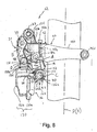
- the cable attachment portion 104 extends from the rearward portion of the upper coupling portion 100, as best seen in Figure 9.
- the cable attachment portion 104 basically includes a threaded through bore 116, a rearwardly facing textured groove 118 and a protrusion 120.
- a cable fixing bolt 122 is preferably threadedly coupled within the threaded bore 116 to hold a cable fixing plate 124 against the rearwardly facing surface of the cable attachment portion 104 to retain the control cable 18 within the textured groove 118.
- the cable fixing plate 124 engages the protrusion 120 to prevent rotation of the cable fixing plate 124 when the cable fixing bolt 122 is rotated.
- the movable member 36 basically includes a chain guide 130, an inner mounting portion 132 and an outer mounting portion 134.
- the movable member 36 is preferably constructed of two pieces of relatively lightweight, hard rigid material that are fixedly coupled together.
- the movable member 36 is preferably constructed of two pieces of a metal material such as a rigid sheet metal that is bent to the desired shape.
- the chain guide 130 has a chain receiving slot that is formed by a pair of vertical shift plates 131a and 131b that are preferably separate pieces. The forward ends of the shift plates 131a and 131b form a front end of the chain guide 130.
- the vertical shift plates 131 a and 131b are adapted to engage the chain 20, and thus, move the chain 20 in a direction substantially transverse to the bicycle 10.
- the shift plates 131a and 131b are connected together by a pair (upper and lower) of plates 131c and 131d in a conventional manner utilizing fasteners such as screw(s), rivet(s) and/or press fitted pin(s).
- the lower plate 131 d together with the rearward ends of the shift plates 131 a and 131b form a rear end of the chain guide 130.
- the vertical shift plates 131a and 131b are adapted to engage the chain 20 to move the chain 20 laterally.
- the shift plate 131a or the shift plate 131b typically contacts the chain 20 to move the chain 20 laterally outwardly or inwardly, respectively.
- each of the shift plates 131a and 131b typically selectively contact the chain 20 at an area O that is spaced longitudinally rearwardly from the inner and outer link members 32 and 34, as seen in Figure 10.
- the lower coupling portion 82 of the inner link member 32 is located rearwardly of the upper coupling portion 80 of the inner link member 32, the chain guide 130 is supported by the inner link member 32 at a location that is longitudinally closer to the area O than the upper coupling portion 80.
- the lower coupling portion 82 of the inner link member 32 is located relatively longitudinally close to the area O to support the chain guide 130. This arrangement contributes to a reduction in bending of the chain guide 130, and thus, improved shifting of the front derailleur 12.
- the inner mounting portion 132 of the movable member 36 includes a pair of longitudinally spaced (front and rear) mounting flanges or attachment elements 136a and 136b extending from the inner shift plate 131a for pivotally coupling the lower coupling portion 82 of the inner link member 32 and the biasing member 38 therebetween via the pivot pin 90.
- the outer mounting portion 134 of the movable member 36 includes a pair of longitudinally spaced (front and rear) mounting flanges or attachment elements 138a and 138b extending from the upper plate 131c of the chain guide 130 for pivotally coupling the lower coupling portion 102 of the outer link member 34 therebetween via the pivot pin 110.
- the mounting flanges or attachment elements 136a, 136b, 138a and 138b are integrally formed with the inner shift plate 131a as a one-piece, unitary member.
- the mounting flanges or attachment elements 136a, 136b, 138a and 138b are preferably configured such that the biasing member 138 is located in front of the lower coupling portion 82 of the inner link member 32 in this embodiment.
- the rear attachment elements 136b and 138b are preferably aligned with each other to contact and/or support the rear surface 96b of the inner link member 32 and the rearward facing surface 114 of the outer link member 34, respectively.
- the front attachment element 136a is preferably located in the forward direction from the front attachment element 138a.
- the front attachment element 136a is preferably located in the forward direction from the front support surface 52 of the base member 30.
- the attachment elements 136a, 136b, 138a and 138b, the pivot pins 90 and 110, and/or the lower coupling portions 82 and 102 can have a low friction coating or material applied thereto and/or a member therebetween to allow smooth movement between these various members.
- the biasing member 38 is preferably a coil spring that is axially mounted on the pivot pin 90 in front of the second coupling portion 82 of the inner link member 32, but rearwardly of the front attachment element 136a of the movable member 36.
- the biasing member 38 preferably includes a front end 140, a rear end 142 and a coiled portion 144 extending between the front and rear ends 140 and 142.
- the rear end 142 preferably extends radially outwardly from the coiled portion 144 and engages the abutment projection 92 of the inner link member 32.
- the front end 140 preferably extends tangentially outwardly from the coiled portion 144 and engages the inner shift plate 131 a of the movable member 36.
- the front end 140 is also supported by the rearward facing surface of the front attachment element 136a of the movable member 36.
- the front end 140 of the biasing member 138 is located in front of the upper coupling portion 80 of the inner link member 32.
- the front derailleur 12 basically operates in a relatively conventional manner to move the chain guide 130 laterally over the three front sprockets 22a, 22b and 22c to shift the chain 20 therebetween. Accordingly, the operation of the front derailleur 12 will not be discussed and/or illustrated in detail herein.
- the link members 32 and 34 move/pivot about the pivot axes A and B against the biasing force of the biasing member 38 to move the chain guide 130 laterally away from the center plane P of the bicycle 10.
- the link members 32 and 34 move/pivot about the pivot axes A and B due to the biasing force of the biasing member 38 in an opposite direction to move the chain guide 130 laterally toward the center plane P of the bicycle 10.
- the movable member 36 is normally biased toward the inner position from the middle and outer positions relative to the center plane P.
- the movable member is also normally biased toward the middle position from the outermost position relative to the center plane P.
- the front derailleur 212 is identical to the front derailleur 12 of the first embodiment, except the front derailleur 212 includes a modified inner link member 232 that has a modified shape.
- the biasing member 38 in this embodiment is identical to the biasing member 38 of the first embodiment.
- the biasing member 38 in this second embodiment is located in a slightly different position relative to the front derailleur 212 due to the arrangement of the modified inner link member 232.
- this second embodiment will not be discussed and/or illustrated in detail herein.
- the inner link member 232 of this second embodiment basically includes an upper coupling portion 280, a pair (front and rear) of longitudinally spaced lower coupling portions 282a and 282b and a transitional portion 284 arranged between the upper and lower coupling portions 280 and 282a/282b.
- the lower coupling portions 282a and 282b are configured to have the biasing member 38 arranged therebetween in this second embodiment.
- the inner link member 232 of this second embodiment is identical to the inner link member 32 of the first embodiment, except the inner link member 232 includes two lower coupling portions 282a and 282b instead of the single lower coupling portion 82 of the first embodiment.
- the inner link member 232 is preferably constructed of a lightweight, rigid material such as metal as a one-piece, unitary member utilizing conventional manufacturing techniques such as casting and/or machining.
- the upper coupling portion 280 is pivotally coupled to the base member 30 via the pivot pin 60 in a manner identical to the first embodiment.
- the upper coupling portion 280 is identical to the upper coupling portion 80 of the first embodiment, except for the connection to the transitional portion 284. In any case, the upper coupling portion 280 functions in a manner identical to the upper coupling portion 80 of the first embodiment.
- the lower coupling portions 282a and 282b are pivotally coupled to the movable member 36 between the pair (front and rear) of attachment elements 136a and 136b via the pivot pin 90.
- the upper coupling portion 280 is wider (thicker) than the each of the lower coupling portions 282a and 282b, and wider (thicker) than the combined width/thickness of the lower coupling portions 282a and 282b together.
- the lower coupling portions 282a and 282b are offset in the forward and rearward directions, respectively from the upper coupling portion 280 such that the biasing member 38 is at least partially located in front of the upper coupling portion 280 relative to the movable member 36 when the front derailleur 212 is coupled to the seat tube 14 of the bicycle frame 13.
- the transitional portion 284 has a substantially inverted V-shape with lower ends coupled to the lower coupling portions 282a and 282b. Thus, the transitional portion 284 has a varying thickness.
- each of the lower coupling portions 282a and 282b is preferably about one-half or only slightly smaller than one-half of the thickness/width of the lower coupling portion 82 of the first embodiment.
- the appropriate amount of space between the lower coupling portions 282a and 282b is provided for the biasing member 38 to be arranged between the lower coupling portions 282a and 282b.
- the lower coupling portion 282b includes an abutment projection 292 identical to the abutment projection 92 of the first embodiment that is configured to engage the biasing member 38 in a manner identical to the first embodiment.
- each of the lower coupling portions 282a and 282b includes a through bore to receive the pivot pin 90.
Landscapes
- Engineering & Computer Science (AREA)
- Chemical & Material Sciences (AREA)
- Combustion & Propulsion (AREA)
- Transportation (AREA)
- Mechanical Engineering (AREA)
- Axle Suspensions And Sidecars For Cycles (AREA)
- Steering Devices For Bicycles And Motorcycles (AREA)
- Motorcycle And Bicycle Frame (AREA)
- Tires In General (AREA)
Abstract
Description
Claims (26)
- A bicycle front derailleur (12, 212) comprising:a base member (30) configured to be coupled to a bicycle frame (13);a movable member (36) having a front end, a rear end and a chain guide portion configured to be moved between first and second positions;a first link member including a first coupling portion pivotally coupled to said base member (30) and a second coupling portion pivotally coupled to said movable member (36) about a first pivot axis, said first link having a forward most surface and a rearward most surface with said forward and rearward most surfaces extending along said first and second coupling portions of said first link member;a second link member including a first coupling portion pivotally coupled to said base member and a second coupling portion pivotally coupled to said movable member about a second pivot axis; anda biasing member (38, 138) disposed on said first pivot axis to normally bias said movable member (36) to said first position relative to said base member (30),said biasing member (38, 138) being at least partially located in front of a section of said forward most surface of said first link member extending along said first coupling portion of said first link member relative to said movable member (36) when said front derailleur (12, 212) is mounted to the bicycle frame (13),said first coupling portion of said second link member including a pair of axially spaced mounting elements pivotally coupled to axially opposed ends of an attachment element of said base member (30).
- The bicycle front derailleur (12, 212) according to claim 1, wherein
said biasing member (38, 138) is axially mounted on a first pin that pivotally couples said movable member (36) to said second coupling portion of said first link member. - The bicycle front derailleur (12, 212) according to claim 1 or 2, wherein
said biasing member (38, 138) is a coil spring with a first spring end engaged with said movable member (36) and a second spring end engaged with said first link member. - The bicycle front derailleur (12, 212) according to any of the preceding claims, wherein
said second link member has a cable attachment portion (104) adapted to fixedly couple a cable thereto. - The bicycle front derailleur (12, 212) according to any of the preceding claims, wherein
said movable member (36) includes a pair of axially spaced attachment elements pivotally coupled to said second coupling portion of said first link member. - The bicycle front derailleur (12, 212) according to any of the preceding claims, wherein
said movable member (36) includes a pair of axially spaced attachment elements pivotally coupled to said second coupling portion of said second link member. - The bicycle front derailleur (12, 212) according to any of the preceding claims, wherein
said base member (30) includes a tubular clamping portion. - The bicycle front derailleur (12, 212) according to any of the preceding claims, wherein
said base member (30) includes first and second axially spaced attachment elements with said first coupling portion of said first link member pivotally coupled between said first and second attachment elements of said base member (30). - The bicycle front derailleur (12, 212) according to any of the preceding claims, wherein
said second coupling portion of said first link member includes a pair of axially spaced mounting elements with said biasing member (38, 138) arranged axially between said mounting elements. - The bicycle front derailleur (12, 212) according to any of the preceding claims, wherein
said first coupling portion of said first link member is located closer to the bicycle frame (13) than said first coupling portion of said second link member when said front derailleur (12, 212) is mounted to the bicycle frame (13), and
said second coupling portion of said first link member is located closer to the to the bicycle frame (13) than said second coupling portion of said second link member when said front derailleur (12, 212) is mounted to the bicycle frame (13). - The bicycle front derailleur (12, 212) according to claim 10, wherein
said second coupling portion of said first link member is located below said first coupling portion of said first link member when said front derailleur (12, 212) is mounted to the bicycle frame (13), and
said second coupling portion of said second link member is located below said first coupling portion of said second link member when said front derailleur (12, 212) is mounted to the bicycle frame (13). - The bicycle front derailleur (12, 212) according to any of the preceding claims, wherein
said first link member includes a first transitional portion arranged between said first coupling portion and said second coupling portions of said first link member such that said second coupling portion of said first link member being located at least partially rearwardly of a section of said rearward most surface of said first link member extending along said first coupling portion of said first link member relative to said base member (30) when said front derailleur (12, 212) is mounted to the bicycle frame (13). - A bicycle front derailleur (12, 212) comprising:a base member (30) configured to be coupled to a bicycle frame (13);a movable member (36) having a front end, a rear end and a chain guide portion configured to be moved between first and second positions;an inner link member including a first coupling portion pivotally coupled to said base member (30) and a second coupling portion pivotally coupled to said movable member (36) about a first pivot axis, said inner link having a forward most surface and a rearward most surface with said forward and rearward most surfaces extending along said first and second coupling portions of said inner link member;an outer link member including a first coupling portion pivotally coupled to said base member (30) and a second coupling portion pivotally coupled to said movable member (36) about a second pivot axis; anda biasing member (38, 138) disposed on said first pivot axis to normally bias said movable member to said first position relative to said base member, said biasing member (38, 138) being at least partially located in front of a section of said forward most surface of said inner link member extending along said first coupling portion of said inner link member relative to said movable member (36) when said front derailleur (12, 212) is mounted to the bicycle frame (13), said biasing member (38, 138) having a front end engaging said movable member and a rear end engaging said inner link member.
- The bicycle front derailleur (12, 212) according to claim 13 and any of claims 2, 3 and 7, wherein
said outer link member has a cable attachment portion adapted to fixedly couple a cable thereto. - The bicycle front derailleur (12, 212) according to claim 13 and any of claims 2, 3 and 7, wherein
said movable member(36) includes a pair of axially spaced attachment elements pivotally coupled to said second coupling portion of said inner link member. - The bicycle front derailleur (12, 212) according to claim 13 and any of claims 2, 3 and 7, wherein
said movable member (36) includes a pair of axially spaced attachment elements pivotally coupled to said second coupling portion of said outer link member. - The bicycle front derailleur (12, 212) according to claim 13 and any of claims 2, 3 and 7, wherein
said base member (30) includes first and second axially spaced attachment elements with said first coupling portion of said inner link member pivotally coupled between said first and second attachment elements of said base member. - The bicycle front derailleur (12, 212) according to claim 13 and any of claims 2, 3 and 7, wherein
said second coupling portion of said inner link member includes a pair of axially spaced mounting elements with said biasing member (38, 138) arranged axially between said mounting elements. - The bicycle front derailleur (12, 212) according to claim 13 and any of claims 2, 3 and 7, wherein
said first coupling portion of said inner link member is located closer to the bicycle frame (13) than said first coupling portion of said outer link member when said front derailleur (12, 212) is mounted to the bicycle frame (13), and
said second coupling portion of said inner link member is located closer to the to the bicycle frame (13) than said second coupling portion of said outer link member when said front derailleur (12, 212) is mounted to the bicycle frame (13). - The bicycle front derailleur (12, 212) according to claim 19, wherein
said second coupling portion of said inner link member is located below said first coupling portion of said inner link member when said front derailleur (12, 212) is mounted to the bicycle frame (13), and
said second coupling portion of said outer link member is located below said first coupling portion of said outer link member when said front derailleur (12, 212) is mounted to the bicycle frame (13). - The bicycle front derailleur (12, 212) according to claim 13 and any of claims 2, 3 and 7, wherein
said inner link member includes a transitional portion arranged between said first coupling portion and said second coupling portions of said inner link member such that said second coupling portion of said inner link member is located at least partially rearwardly of a section of said rearward most surface of said inner link member extending along said first coupling portion of said inner link member relative to said base member (30) when said front derailleur (12, 212) is mounted to the bicycle frame(13). - The bicycle front derailleur (12, 212) according to claim 13 and any of claims 2, 3 and 7, wherein
said first coupling portion of said outer link member includes a pair of axially spaced mounting elements pivotally coupled to axially opposed ends of an attachment element of said base member. - A bicycle front derailleur (12, 212) comprising:a base member (30) configured to be coupled to a bicycle frame (13);a movable member (36) having a front end, a rear end and a chain guide portion configured to be moved between first and second positions;a first link member including a first coupling portion pivotally coupled to said base member (30) and a second coupling portion pivotally coupled to said movable member (36) about a first pivot axis, said first link having a forward most surface and a rearward most surface with said forward and rearward most surfaces extending along said first and second coupling portions of said first link member;a second link member including a first coupling portion pivotally coupled to said base member (30) and a second coupling portion pivotally coupled to said movable member (36) about a second pivot axis; anda biasing member (38, 138) disposed on said first pivot axis to normally bias said movable member (36) to said first position relative to said base member (30),said biasing member (38, 138) being at least partially located in front of a section of said forward most surface of said first link member extending along said first coupling portion of said first link member relative to said movable member (36) when said front derailleur (12, 212) is mounted to the bicycle frame (13),said first link member including a first transitional portion arranged between said first and second coupling portions of said first link member such that said second coupling portion of said first link member is located at least partially rearwardly of a section of said rearward most surface of said first link member extending along said first coupling portion of said first link member relative to said movable member (36) when said front derailleur (12, 212) is mounted to the bicycle frame (13).
- The bicycle front derailleur (12, 212) according to claim 26 and any of claims 2 to 10, wherein
said second coupling portion of said first link member is located below said first coupling portion of said first link member when said front derailleur (12, 212) is mounted to the bicycle frame (13), and
said second coupling portion of said second link member is located below said first coupling portion of said second link member when said front derailleur (12, 212) is mounted to the bicycle frame (13). - A bicycle front derailleur (12, 212) comprising:a base member (30) configured to be coupled to a bicycle frame (13);a movable member (36) having a front end, a rear end and a chain guide portion configured to be moved between first and second positions;a first link member including a first coupling portion pivotally coupled to said base member (30) and a second coupling portion pivotally coupled to said movable member (36) about a first pivot axis, said first link having a forward most surface and a rear ward most surface with said forward and rearward most surfaces extending along said first and second coupling portions of said first link member;a second link member including a first coupling portion pivotally coupled to said base member (30) and a second coupling portion pivotally coupled to said movable member (36) about a second pivot axis; anda biasing member (38, 138) disposed on said first pivot axis to normally bias said movable member (36) to said first position relative to said base member (30), said biasing member (38, 138) being at least partially located in front of a section of said forward most surface of said first link member extending along said first coupling portion of said first link member relative to said movable member (36) when said front derailleur (12, 212) is mounted to the bicycle frame (13), said biasing member (38, 138) having a frond end engaging said movable member (36) and a rear end engaging said inner link member,said second link member having a cable attachment portion configured to have a control cable coupled thereto.
- The bicycle front derailleur (12, 212) according to claim 25 and any of claims 10 and 11, wherein
said cable attachment portion of said second link member is located above said first coupling portion of said second link member when said front derailleur (12, 212) is mounted to the bicycle.
Priority Applications (1)
| Application Number | Priority Date | Filing Date | Title |
|---|---|---|---|
| DE602004002000T DE602004002000T4 (en) | 2003-02-12 | 2004-02-11 | Front derailleur for a bicycle |
Applications Claiming Priority (2)
| Application Number | Priority Date | Filing Date | Title |
|---|---|---|---|
| US364350 | 1982-04-01 | ||
| US10/364,350 US7081058B2 (en) | 2003-02-12 | 2003-02-12 | Bicycle front derailleur |
Publications (4)
| Publication Number | Publication Date |
|---|---|
| EP1447317A2 true EP1447317A2 (en) | 2004-08-18 |
| EP1447317A3 EP1447317A3 (en) | 2005-06-01 |
| EP1447317B1 EP1447317B1 (en) | 2006-08-23 |
| EP1447317B2 EP1447317B2 (en) | 2011-09-07 |
Family
ID=32681693
Family Applications (1)
| Application Number | Title | Priority Date | Filing Date |
|---|---|---|---|
| EP04003074A Expired - Lifetime EP1447317B2 (en) | 2003-02-12 | 2004-02-11 | Bicycle front derailleur |
Country Status (7)
| Country | Link |
|---|---|
| US (2) | US7081058B2 (en) |
| EP (1) | EP1447317B2 (en) |
| JP (1) | JP2004244013A (en) |
| CN (1) | CN100335352C (en) |
| AT (1) | ATE337219T1 (en) |
| DE (1) | DE602004002000T4 (en) |
| TW (1) | TWI283216B (en) |
Cited By (5)
| Publication number | Priority date | Publication date | Assignee | Title |
|---|---|---|---|---|
| EP1944230A3 (en) * | 2007-01-09 | 2009-11-04 | Shimano (Singapore) Private Limited | Bicycle front derailleur |
| EP2168865A2 (en) | 2008-09-29 | 2010-03-31 | SRAM Deutschland GmbH | Chain switching for a bicycle |
| EP1746020A3 (en) * | 2005-07-22 | 2010-06-09 | SRAM Deutschland GmbH | Articulated joint |
| EP2572972A1 (en) * | 2011-09-21 | 2013-03-27 | Shimano Inc. | Bicycle front derailleur |
| TWI579196B (en) * | 2012-10-18 | 2017-04-21 | 速聯有限責任公司 | Front gear changer |
Families Citing this family (34)
| Publication number | Priority date | Publication date | Assignee | Title |
|---|---|---|---|---|
| US7331890B2 (en) * | 2004-02-26 | 2008-02-19 | Shimano Inc. | Motorized front derailleur mounting member |
| US7438657B2 (en) * | 2005-05-27 | 2008-10-21 | Shimano Inc. | Bicycle front derailleur |
| DE102005050988A1 (en) * | 2005-10-25 | 2007-06-14 | Sram Deutschland Gmbh | derailleur |
| US20070191158A1 (en) * | 2006-02-01 | 2007-08-16 | Shimano Inc. | Bicycle front derailleur |
| US20080004142A1 (en) * | 2006-06-08 | 2008-01-03 | Shimano Inc. | Bicycle front derailleur |
| ITMI20070883A1 (en) | 2007-05-03 | 2008-11-04 | Campagnolo Srl | FRONT DERAILLEUR FOR A BICYCLE |
| US7914407B2 (en) * | 2007-05-29 | 2011-03-29 | Shimano Inc. | Bicycle front derailleur assembly |
| ITMI20072062A1 (en) * | 2007-10-25 | 2009-04-26 | Campagnolo Srl | BICYCLE CHANGE |
| DE102010011391A1 (en) * | 2010-03-12 | 2011-09-15 | Sram Deutschland Gmbh | Cable operated device for bicycle derailleurs |
| US8852041B2 (en) * | 2010-09-30 | 2014-10-07 | Shimano, Inc. | Bicycle derailleur with rotation resistance |
| US9284017B2 (en) * | 2010-12-15 | 2016-03-15 | Sram, Llc | Bicycle derailleur and method |
| US8678962B2 (en) * | 2010-12-15 | 2014-03-25 | Sram, Llc | Bicycle derailleur and method |
| US9327792B2 (en) | 2011-01-28 | 2016-05-03 | Paha Designs, Llc | Gear transmission and derailleur system |
| US10207772B2 (en) | 2011-01-28 | 2019-02-19 | Paha Designs, Llc | Gear transmission and derailleur system |
| US9033833B2 (en) | 2011-01-28 | 2015-05-19 | Paha Designs, Llc | Gear transmission and derailleur system |
| US9067641B2 (en) * | 2011-10-03 | 2015-06-30 | Shimano, Inc. | Bicycle front derailleur with a variable actuation ratio |
| JP2015016791A (en) * | 2013-07-11 | 2015-01-29 | 株式会社シマノ | Front derailer |
| JP2015016792A (en) * | 2013-07-11 | 2015-01-29 | 株式会社シマノ | Front derailer |
| US9248885B2 (en) * | 2013-09-30 | 2016-02-02 | Shimano Inc. | Derailleur |
| US9457871B2 (en) | 2014-09-08 | 2016-10-04 | Shimano Inc. | Bicycle front derailleur |
| US9434448B2 (en) * | 2014-10-31 | 2016-09-06 | Shimano Inc. | Bicycle derailleur |
| US10065705B2 (en) * | 2015-02-05 | 2018-09-04 | Shimano Inc. | Bicycle derailleur |
| US9616970B2 (en) * | 2015-07-03 | 2017-04-11 | Shimano Inc. | Bicycle derailleur |
| US10086905B2 (en) * | 2016-03-22 | 2018-10-02 | Shimano Inc. | Bicycle front derailleur with mounting bracket |
| US10407128B2 (en) * | 2016-09-30 | 2019-09-10 | Shimano Inc. | Bicycle derailleur |
| US10131404B2 (en) * | 2017-02-09 | 2018-11-20 | Shimano Inc. | Bicycle front derailleur |
| IT201700015324A1 (en) * | 2017-02-13 | 2018-08-13 | Campagnolo Srl | Front derailleur for bicycle |
| IT201700021438A1 (en) * | 2017-02-24 | 2018-08-24 | Campagnolo Srl | Bicycle derailleur |
| IT201700021394A1 (en) | 2017-02-24 | 2018-08-24 | Campagnolo Srl | Bicycle derailleur |
| CN106985959B (en) * | 2017-03-28 | 2022-05-27 | 珠海蓝图控制器科技有限公司 | Bicycle front derailleur |
| TWI743181B (en) * | 2017-08-25 | 2021-10-21 | 日商島野股份有限公司 | Derailleur for bicycle |
| TWI752306B (en) * | 2019-03-20 | 2022-01-11 | 彥豪金屬工業股份有限公司 | Bicycle derailleur |
| DE102021201743A1 (en) * | 2021-02-24 | 2022-08-25 | Shimano (Singapore) Pte Ltd. | A CLAMP STRUCTURE AND A BICYCLE DERAILLEUR |
| US11787506B2 (en) * | 2021-03-30 | 2023-10-17 | Shimano Inc. | Derailleur for human-powered vehicle |
Family Cites Families (27)
| Publication number | Priority date | Publication date | Assignee | Title |
|---|---|---|---|---|
| FR2093242A5 (en) | 1970-06-08 | 1972-01-28 | Juy Lucien | |
| FR2294079A1 (en) | 1974-12-12 | 1976-07-09 | Shimano Industrial Co | FRONT DERAILLEUR FOR A BICYCLE |
| IT7522155U1 (en) | 1975-08-29 | 1977-03-01 | Campagnolo Tullio | CENTRAL DERAILLEUR OF THE DRIVE CHAIN FOR BICYCLES WITH MULTIPLE-SPEED CENTRAL GEAR MADE WITH PARTICULARLY ECONOMICAL CITRERI |
| FR2340852A1 (en) | 1976-02-13 | 1977-09-09 | Huret Jacques | FRONT DERAILLEUR CHAIN GUIDE FOR BICYCLES |
| JPS5383246A (en) | 1976-12-28 | 1978-07-22 | Shimano Industrial Co | Derailer for bicycle |
| US4226130A (en) | 1977-09-05 | 1980-10-07 | Shimano Industrial Company, Limited | Front derailleur for a bicycle |
| US4237743A (en) | 1977-10-11 | 1980-12-09 | Shimano Industrial Company, Limited | Front derailleur for a bicycle |
| US4279605A (en) | 1978-09-13 | 1981-07-21 | Shimano Industrial Company Limited | Front derailleur for a bicycle |
| JPS5921830B2 (en) | 1980-07-16 | 1984-05-22 | マエダ工業株式会社 | Bicycle front derailleur |
| FR2502101A1 (en) * | 1981-03-17 | 1982-09-24 | Simplex Ets | CHANGE OF SPEED TO THE CYCLES PEDAL AND SIMILAR VEHICLES |
| FR2518953A1 (en) | 1981-12-30 | 1983-07-01 | Huret & Fils | DERAILLEUR WITH ADJUSTABLE CRANKSET |
| JPS6034090U (en) | 1983-08-16 | 1985-03-08 | 株式会社シマノ | bicycle front derailleur |
| JPS60206793A (en) | 1984-03-29 | 1985-10-18 | 株式会社シマノ | Front derailer for three step gear change |
| EP0199279A3 (en) * | 1985-04-22 | 1987-09-23 | Karl Huber Verpackungswerke GmbH + Co. | Manufacturing process of a folded edge |
| JPH0829743B2 (en) | 1986-04-11 | 1996-03-27 | 島野工業株式会社 | Bicycle front derailleur |
| JPH0322071Y2 (en) | 1986-07-10 | 1991-05-14 | ||
| JPH0716554Y2 (en) | 1988-06-30 | 1995-04-19 | 島野工業株式会社 | Bicycle front derailleur |
| JPH0535920Y2 (en) | 1989-09-05 | 1993-09-10 | ||
| JPH0352297U (en) | 1989-09-28 | 1991-05-21 | ||
| US5312301A (en) | 1991-11-29 | 1994-05-17 | Maeda Industries, Ltd. | Bicycle front derailleur |
| EP0653347B1 (en) | 1993-11-12 | 2000-03-01 | Shimano Inc. | Front gear for a bicycle |
| JP3458016B2 (en) | 1994-12-20 | 2003-10-20 | 株式会社シマノ | Bicycle front derailleur |
| IT1279173B1 (en) | 1995-03-20 | 1997-12-04 | Campagnolo Srl | AUXILIARY ORGAN TO FACILITATE THE ASSEMBLY OF A BICYCLE FRONT DERAILLEUR. |
| US6234927B1 (en) | 1999-02-26 | 2001-05-22 | Shimano (Singapore) Pte., Ltd. | Front derailleur for a bicycle |
| US6146298A (en) * | 1999-03-29 | 2000-11-14 | Shimano, Inc. | Band adapter for front derailleur |
| IT1320646B1 (en) | 2000-09-15 | 2003-12-10 | Campagnolo Srl | FRONT DERAILLEUR FORK OF BICYCLE, AND FRONT DERAILLEUR INCLUDING SUCH FORK. |
| US7014584B2 (en) * | 2002-12-27 | 2006-03-21 | Shimano Inc. | Top pull type front derailleur |
-
2003
- 2003-02-12 US US10/364,350 patent/US7081058B2/en not_active Expired - Fee Related
-
2004
- 2004-02-10 JP JP2004033746A patent/JP2004244013A/en not_active Withdrawn
- 2004-02-11 AT AT04003074T patent/ATE337219T1/en not_active IP Right Cessation
- 2004-02-11 EP EP04003074A patent/EP1447317B2/en not_active Expired - Lifetime
- 2004-02-11 DE DE602004002000T patent/DE602004002000T4/en not_active Expired - Lifetime
- 2004-02-11 TW TW093103210A patent/TWI283216B/en not_active IP Right Cessation
- 2004-02-11 CN CNB2004100053378A patent/CN100335352C/en not_active Expired - Fee Related
-
2005
- 2005-10-25 US US11/257,108 patent/US7186194B2/en not_active Expired - Fee Related
Cited By (14)
| Publication number | Priority date | Publication date | Assignee | Title |
|---|---|---|---|---|
| EP1746020A3 (en) * | 2005-07-22 | 2010-06-09 | SRAM Deutschland GmbH | Articulated joint |
| US8109848B2 (en) | 2005-07-22 | 2012-02-07 | Sram Deutschland Gmbh | Pivotal connection of a bicycle derailleur |
| EP1944230A3 (en) * | 2007-01-09 | 2009-11-04 | Shimano (Singapore) Private Limited | Bicycle front derailleur |
| US9132885B2 (en) | 2008-09-29 | 2015-09-15 | Sram, Llc | Bicycle derailleur |
| DE102008049360A1 (en) | 2008-09-29 | 2010-04-08 | Sram Deutschland Gmbh | Derailleur for a bicycle |
| EP2168865A3 (en) * | 2008-09-29 | 2013-01-02 | SRAM Deutschland GmbH | Chain switching for a bicycle |
| EP2669169A1 (en) | 2008-09-29 | 2013-12-04 | SRAM Deutschland GmbH | Gear changer for a bicycle |
| EP2168865A2 (en) | 2008-09-29 | 2010-03-31 | SRAM Deutschland GmbH | Chain switching for a bicycle |
| EP2669169B1 (en) | 2008-09-29 | 2016-01-13 | SRAM Deutschland GmbH | Gear changer for a bicycle |
| EP2572972A1 (en) * | 2011-09-21 | 2013-03-27 | Shimano Inc. | Bicycle front derailleur |
| US8678963B2 (en) | 2011-09-21 | 2014-03-25 | Shimano Inc. | Bicycle front derailleur |
| TWI579196B (en) * | 2012-10-18 | 2017-04-21 | 速聯有限責任公司 | Front gear changer |
| US10876607B2 (en) | 2012-10-18 | 2020-12-29 | Sram, Llc | Front gear changer |
| US12523277B2 (en) | 2012-10-18 | 2026-01-13 | Sram, Llc | Front gear changer |
Also Published As
| Publication number | Publication date |
|---|---|
| TW200418686A (en) | 2004-10-01 |
| EP1447317B2 (en) | 2011-09-07 |
| DE602004002000T3 (en) | 2012-01-26 |
| US20060035737A1 (en) | 2006-02-16 |
| DE602004002000D1 (en) | 2006-10-05 |
| TWI283216B (en) | 2007-07-01 |
| EP1447317A3 (en) | 2005-06-01 |
| DE602004002000T4 (en) | 2013-08-08 |
| EP1447317B1 (en) | 2006-08-23 |
| US7186194B2 (en) | 2007-03-06 |
| US7081058B2 (en) | 2006-07-25 |
| ATE337219T1 (en) | 2006-09-15 |
| CN100335352C (en) | 2007-09-05 |
| DE602004002000T2 (en) | 2006-12-14 |
| US20040157690A1 (en) | 2004-08-12 |
| CN1533945A (en) | 2004-10-06 |
| JP2004244013A (en) | 2004-09-02 |
Similar Documents
| Publication | Publication Date | Title |
|---|---|---|
| EP1447317B1 (en) | Bicycle front derailleur | |
| EP1314636B2 (en) | Front derailleur for bicycle | |
| US7722489B2 (en) | Bicycle front derailleur | |
| US8485924B2 (en) | Bicycle chain guide | |
| EP1433696B2 (en) | Front derailleur | |
| US7914407B2 (en) | Bicycle front derailleur assembly | |
| US6902503B2 (en) | Bicycle derailleur | |
| US7677998B2 (en) | Bicycle front derailleur | |
| US7651424B2 (en) | Bicycle front derailleur | |
| US7722486B2 (en) | Top/bottom pull bicycle front derailleur |
Legal Events
| Date | Code | Title | Description |
|---|---|---|---|
| PUAI | Public reference made under article 153(3) epc to a published international application that has entered the european phase |
Free format text: ORIGINAL CODE: 0009012 |
|
| AK | Designated contracting states |
Kind code of ref document: A2 Designated state(s): AT BE BG CH CY CZ DE DK EE ES FI FR GB GR HU IE IT LI LU MC NL PT RO SE SI SK TR |
|
| AX | Request for extension of the european patent |
Extension state: AL LT LV MK |
|
| PUAL | Search report despatched |
Free format text: ORIGINAL CODE: 0009013 |
|
| AK | Designated contracting states |
Kind code of ref document: A3 Designated state(s): AT BE BG CH CY CZ DE DK EE ES FI FR GB GR HU IE IT LI LU MC NL PT RO SE SI SK TR |
|
| AX | Request for extension of the european patent |
Extension state: AL LT LV MK |
|
| 17P | Request for examination filed |
Effective date: 20050517 |
|
| 17Q | First examination report despatched |
Effective date: 20050704 |
|
| GRAP | Despatch of communication of intention to grant a patent |
Free format text: ORIGINAL CODE: EPIDOSNIGR1 |
|
| AKX | Designation fees paid |
Designated state(s): AT BE BG CH CY CZ DE DK EE ES FI FR GB GR HU IE IT LI LU MC NL PT RO SE SI SK TR |
|
| GRAS | Grant fee paid |
Free format text: ORIGINAL CODE: EPIDOSNIGR3 |
|
| GRAA | (expected) grant |
Free format text: ORIGINAL CODE: 0009210 |
|
| RAP1 | Party data changed (applicant data changed or rights of an application transferred) |
Owner name: SHIMANO INC. |
|
| AK | Designated contracting states |
Kind code of ref document: B1 Designated state(s): AT BE BG CH CY CZ DE DK EE ES FI FR GB GR HU IE IT LI LU MC NL PT RO SE SI SK TR |
|
| PG25 | Lapsed in a contracting state [announced via postgrant information from national office to epo] |
Ref country code: CH Free format text: LAPSE BECAUSE OF FAILURE TO SUBMIT A TRANSLATION OF THE DESCRIPTION OR TO PAY THE FEE WITHIN THE PRESCRIBED TIME-LIMIT Effective date: 20060823 Ref country code: IT Free format text: LAPSE BECAUSE OF FAILURE TO SUBMIT A TRANSLATION OF THE DESCRIPTION OR TO PAY THE FEE WITHIN THE PRESCRIBED TIME-LIMIT;WARNING: LAPSES OF ITALIAN PATENTS WITH EFFECTIVE DATE BEFORE 2007 MAY HAVE OCCURRED AT ANY TIME BEFORE 2007. THE CORRECT EFFECTIVE DATE MAY BE DIFFERENT FROM THE ONE RECORDED. Effective date: 20060823 Ref country code: LI Free format text: LAPSE BECAUSE OF FAILURE TO SUBMIT A TRANSLATION OF THE DESCRIPTION OR TO PAY THE FEE WITHIN THE PRESCRIBED TIME-LIMIT Effective date: 20060823 Ref country code: RO Free format text: LAPSE BECAUSE OF FAILURE TO SUBMIT A TRANSLATION OF THE DESCRIPTION OR TO PAY THE FEE WITHIN THE PRESCRIBED TIME-LIMIT Effective date: 20060823 Ref country code: SK Free format text: LAPSE BECAUSE OF FAILURE TO SUBMIT A TRANSLATION OF THE DESCRIPTION OR TO PAY THE FEE WITHIN THE PRESCRIBED TIME-LIMIT Effective date: 20060823 Ref country code: SI Free format text: LAPSE BECAUSE OF FAILURE TO SUBMIT A TRANSLATION OF THE DESCRIPTION OR TO PAY THE FEE WITHIN THE PRESCRIBED TIME-LIMIT Effective date: 20060823 Ref country code: FI Free format text: LAPSE BECAUSE OF FAILURE TO SUBMIT A TRANSLATION OF THE DESCRIPTION OR TO PAY THE FEE WITHIN THE PRESCRIBED TIME-LIMIT Effective date: 20060823 Ref country code: CZ Free format text: LAPSE BECAUSE OF FAILURE TO SUBMIT A TRANSLATION OF THE DESCRIPTION OR TO PAY THE FEE WITHIN THE PRESCRIBED TIME-LIMIT Effective date: 20060823 Ref country code: AT Free format text: LAPSE BECAUSE OF FAILURE TO SUBMIT A TRANSLATION OF THE DESCRIPTION OR TO PAY THE FEE WITHIN THE PRESCRIBED TIME-LIMIT Effective date: 20060823 Ref country code: BE Free format text: LAPSE BECAUSE OF FAILURE TO SUBMIT A TRANSLATION OF THE DESCRIPTION OR TO PAY THE FEE WITHIN THE PRESCRIBED TIME-LIMIT Effective date: 20060823 |
|
| REG | Reference to a national code |
Ref country code: GB Ref legal event code: FG4D |
|
| REG | Reference to a national code |
Ref country code: CH Ref legal event code: EP |
|
| REG | Reference to a national code |
Ref country code: IE Ref legal event code: FG4D |
|
| REF | Corresponds to: |
Ref document number: 602004002000 Country of ref document: DE Date of ref document: 20061005 Kind code of ref document: P |
|
| PG25 | Lapsed in a contracting state [announced via postgrant information from national office to epo] |
Ref country code: SE Free format text: LAPSE BECAUSE OF FAILURE TO SUBMIT A TRANSLATION OF THE DESCRIPTION OR TO PAY THE FEE WITHIN THE PRESCRIBED TIME-LIMIT Effective date: 20061123 Ref country code: BG Free format text: LAPSE BECAUSE OF FAILURE TO SUBMIT A TRANSLATION OF THE DESCRIPTION OR TO PAY THE FEE WITHIN THE PRESCRIBED TIME-LIMIT Effective date: 20061123 Ref country code: DK Free format text: LAPSE BECAUSE OF FAILURE TO SUBMIT A TRANSLATION OF THE DESCRIPTION OR TO PAY THE FEE WITHIN THE PRESCRIBED TIME-LIMIT Effective date: 20061123 |
|
| PG25 | Lapsed in a contracting state [announced via postgrant information from national office to epo] |
Ref country code: ES Free format text: LAPSE BECAUSE OF FAILURE TO SUBMIT A TRANSLATION OF THE DESCRIPTION OR TO PAY THE FEE WITHIN THE PRESCRIBED TIME-LIMIT Effective date: 20061204 |
|
| PG25 | Lapsed in a contracting state [announced via postgrant information from national office to epo] |
Ref country code: PT Free format text: LAPSE BECAUSE OF FAILURE TO SUBMIT A TRANSLATION OF THE DESCRIPTION OR TO PAY THE FEE WITHIN THE PRESCRIBED TIME-LIMIT Effective date: 20070125 |
|
| PG25 | Lapsed in a contracting state [announced via postgrant information from national office to epo] |
Ref country code: MC Free format text: LAPSE BECAUSE OF NON-PAYMENT OF DUE FEES Effective date: 20070228 |
|
| REG | Reference to a national code |
Ref country code: CH Ref legal event code: PL |
|
| EN | Fr: translation not filed | ||
| PLBI | Opposition filed |
Free format text: ORIGINAL CODE: 0009260 |
|
| PLAX | Notice of opposition and request to file observation + time limit sent |
Free format text: ORIGINAL CODE: EPIDOSNOBS2 |
|
| 26 | Opposition filed |
Opponent name: SRAM DEUTSCHLAND GMBH Effective date: 20070515 |
|
| NLR1 | Nl: opposition has been filed with the epo |
Opponent name: SRAM DEUTSCHLAND GMBH |
|
| PLAF | Information modified related to communication of a notice of opposition and request to file observations + time limit |
Free format text: ORIGINAL CODE: EPIDOSCOBS2 |
|
| PLAF | Information modified related to communication of a notice of opposition and request to file observations + time limit |
Free format text: ORIGINAL CODE: EPIDOSCOBS2 |
|
| PG25 | Lapsed in a contracting state [announced via postgrant information from national office to epo] |
Ref country code: IE Free format text: LAPSE BECAUSE OF NON-PAYMENT OF DUE FEES Effective date: 20070212 |
|
| PLBB | Reply of patent proprietor to notice(s) of opposition received |
Free format text: ORIGINAL CODE: EPIDOSNOBS3 |
|
| PG25 | Lapsed in a contracting state [announced via postgrant information from national office to epo] |
Ref country code: FR Free format text: LAPSE BECAUSE OF FAILURE TO SUBMIT A TRANSLATION OF THE DESCRIPTION OR TO PAY THE FEE WITHIN THE PRESCRIBED TIME-LIMIT Effective date: 20070511 Ref country code: GR Free format text: LAPSE BECAUSE OF FAILURE TO SUBMIT A TRANSLATION OF THE DESCRIPTION OR TO PAY THE FEE WITHIN THE PRESCRIBED TIME-LIMIT Effective date: 20061124 |
|
| PG25 | Lapsed in a contracting state [announced via postgrant information from national office to epo] |
Ref country code: EE Free format text: LAPSE BECAUSE OF FAILURE TO SUBMIT A TRANSLATION OF THE DESCRIPTION OR TO PAY THE FEE WITHIN THE PRESCRIBED TIME-LIMIT Effective date: 20060823 |
|
| GBPC | Gb: european patent ceased through non-payment of renewal fee |
Effective date: 20080211 |
|
| NLV4 | Nl: lapsed or anulled due to non-payment of the annual fee |
Effective date: 20080901 |
|
| PG25 | Lapsed in a contracting state [announced via postgrant information from national office to epo] |
Ref country code: FR Free format text: LAPSE BECAUSE OF FAILURE TO SUBMIT A TRANSLATION OF THE DESCRIPTION OR TO PAY THE FEE WITHIN THE PRESCRIBED TIME-LIMIT Effective date: 20060823 Ref country code: NL Free format text: LAPSE BECAUSE OF NON-PAYMENT OF DUE FEES Effective date: 20080901 |
|
| PG25 | Lapsed in a contracting state [announced via postgrant information from national office to epo] |
Ref country code: GB Free format text: LAPSE BECAUSE OF NON-PAYMENT OF DUE FEES Effective date: 20080211 |
|
| PG25 | Lapsed in a contracting state [announced via postgrant information from national office to epo] |
Ref country code: CY Free format text: LAPSE BECAUSE OF FAILURE TO SUBMIT A TRANSLATION OF THE DESCRIPTION OR TO PAY THE FEE WITHIN THE PRESCRIBED TIME-LIMIT Effective date: 20060823 Ref country code: LU Free format text: LAPSE BECAUSE OF NON-PAYMENT OF DUE FEES Effective date: 20070211 |
|
| PG25 | Lapsed in a contracting state [announced via postgrant information from national office to epo] |
Ref country code: HU Free format text: LAPSE BECAUSE OF FAILURE TO SUBMIT A TRANSLATION OF THE DESCRIPTION OR TO PAY THE FEE WITHIN THE PRESCRIBED TIME-LIMIT Effective date: 20070224 Ref country code: TR Free format text: LAPSE BECAUSE OF FAILURE TO SUBMIT A TRANSLATION OF THE DESCRIPTION OR TO PAY THE FEE WITHIN THE PRESCRIBED TIME-LIMIT Effective date: 20060823 |
|
| PUAH | Patent maintained in amended form |
Free format text: ORIGINAL CODE: 0009272 |
|
| STAA | Information on the status of an ep patent application or granted ep patent |
Free format text: STATUS: PATENT MAINTAINED AS AMENDED |
|
| 27A | Patent maintained in amended form |
Effective date: 20110907 |
|
| AK | Designated contracting states |
Kind code of ref document: B2 Designated state(s): AT BE BG CH CY CZ DE DK EE ES FI FR GB GR HU IE IT LI LU MC NL PT RO SE SI SK TR |
|
| REG | Reference to a national code |
Ref country code: DE Ref legal event code: R102 Ref document number: 602004002000 Country of ref document: DE |
|
| REG | Reference to a national code |
Ref country code: DE Ref legal event code: R102 Ref document number: 602004002000 Country of ref document: DE Effective date: 20110907 |
|
| REG | Reference to a national code |
Ref country code: DE Ref legal event code: R082 Ref document number: 602004002000 Country of ref document: DE Representative=s name: GROSSE, SCHUMACHER, KNAUER VON HIRSCHHAUSEN, DE Ref country code: DE Ref legal event code: R082 Ref document number: 602004002000 Country of ref document: DE Representative=s name: GROSSE, SCHUMACHER, KNAUER, VON HIRSCHHAUSEN, DE |
|
| PGFP | Annual fee paid to national office [announced via postgrant information from national office to epo] |
Ref country code: IT Payment date: 20170221 Year of fee payment: 14 |
|
| PG25 | Lapsed in a contracting state [announced via postgrant information from national office to epo] |
Ref country code: IT Free format text: LAPSE BECAUSE OF NON-PAYMENT OF DUE FEES Effective date: 20180211 |
|
| PGFP | Annual fee paid to national office [announced via postgrant information from national office to epo] |
Ref country code: DE Payment date: 20200129 Year of fee payment: 17 |
|
| REG | Reference to a national code |
Ref country code: DE Ref legal event code: R119 Ref document number: 602004002000 Country of ref document: DE |
|
| PG25 | Lapsed in a contracting state [announced via postgrant information from national office to epo] |
Ref country code: DE Free format text: LAPSE BECAUSE OF NON-PAYMENT OF DUE FEES Effective date: 20210901 |