EP1447311A1 - Luggage storage structure for automobile and lifter - Google Patents
Luggage storage structure for automobile and lifter Download PDFInfo
- Publication number
- EP1447311A1 EP1447311A1 EP04003409A EP04003409A EP1447311A1 EP 1447311 A1 EP1447311 A1 EP 1447311A1 EP 04003409 A EP04003409 A EP 04003409A EP 04003409 A EP04003409 A EP 04003409A EP 1447311 A1 EP1447311 A1 EP 1447311A1
- Authority
- EP
- European Patent Office
- Prior art keywords
- plate member
- link
- luggage
- slider
- drive link
- Prior art date
- Legal status (The legal status is an assumption and is not a legal conclusion. Google has not performed a legal analysis and makes no representation as to the accuracy of the status listed.)
- Granted
Links
Images







Classifications
-
- B—PERFORMING OPERATIONS; TRANSPORTING
- B66—HOISTING; LIFTING; HAULING
- B66F—HOISTING, LIFTING, HAULING OR PUSHING, NOT OTHERWISE PROVIDED FOR, e.g. DEVICES WHICH APPLY A LIFTING OR PUSHING FORCE DIRECTLY TO THE SURFACE OF A LOAD
- B66F7/00—Lifting frames, e.g. for lifting vehicles; Platform lifts
- B66F7/06—Lifting frames, e.g. for lifting vehicles; Platform lifts with platforms supported by levers for vertical movement
- B66F7/065—Scissor linkages, i.e. X-configuration
-
- B—PERFORMING OPERATIONS; TRANSPORTING
- B60—VEHICLES IN GENERAL
- B60R—VEHICLES, VEHICLE FITTINGS, OR VEHICLE PARTS, NOT OTHERWISE PROVIDED FOR
- B60R5/00—Compartments within vehicle body primarily intended or sufficiently spacious for trunks, suit-cases, or the like
- B60R5/04—Compartments within vehicle body primarily intended or sufficiently spacious for trunks, suit-cases, or the like arranged at rear of vehicle
-
- B—PERFORMING OPERATIONS; TRANSPORTING
- B60—VEHICLES IN GENERAL
- B60R—VEHICLES, VEHICLE FITTINGS, OR VEHICLE PARTS, NOT OTHERWISE PROVIDED FOR
- B60R5/00—Compartments within vehicle body primarily intended or sufficiently spacious for trunks, suit-cases, or the like
- B60R5/04—Compartments within vehicle body primarily intended or sufficiently spacious for trunks, suit-cases, or the like arranged at rear of vehicle
- B60R5/044—Compartments within vehicle body primarily intended or sufficiently spacious for trunks, suit-cases, or the like arranged at rear of vehicle luggage covering means, e.g. parcel shelves
- B60R5/045—Compartments within vehicle body primarily intended or sufficiently spacious for trunks, suit-cases, or the like arranged at rear of vehicle luggage covering means, e.g. parcel shelves collapsible or transformable
-
- B—PERFORMING OPERATIONS; TRANSPORTING
- B62—LAND VEHICLES FOR TRAVELLING OTHERWISE THAN ON RAILS
- B62D—MOTOR VEHICLES; TRAILERS
- B62D43/00—Spare wheel stowing, holding, or mounting arrangements
- B62D43/06—Spare wheel stowing, holding, or mounting arrangements within the vehicle body
- B62D43/10—Spare wheel stowing, holding, or mounting arrangements within the vehicle body and arranged substantially horizontally
-
- B—PERFORMING OPERATIONS; TRANSPORTING
- B66—HOISTING; LIFTING; HAULING
- B66F—HOISTING, LIFTING, HAULING OR PUSHING, NOT OTHERWISE PROVIDED FOR, e.g. DEVICES WHICH APPLY A LIFTING OR PUSHING FORCE DIRECTLY TO THE SURFACE OF A LOAD
- B66F7/00—Lifting frames, e.g. for lifting vehicles; Platform lifts
- B66F7/06—Lifting frames, e.g. for lifting vehicles; Platform lifts with platforms supported by levers for vertical movement
- B66F7/08—Lifting frames, e.g. for lifting vehicles; Platform lifts with platforms supported by levers for vertical movement hydraulically or pneumatically operated
-
- B—PERFORMING OPERATIONS; TRANSPORTING
- B60—VEHICLES IN GENERAL
- B60R—VEHICLES, VEHICLE FITTINGS, OR VEHICLE PARTS, NOT OTHERWISE PROVIDED FOR
- B60R13/00—Elements for body-finishing, identifying, or decorating; Arrangements or adaptations for advertising purposes
- B60R13/01—Liners for load platforms or load compartments
Definitions
- the present invention relates to a luggage storage structure for an automobile for storing a luggage in a storage concave portion formed in a floor panel, and a lifter for transferring a plate member for the luggage at least upwardly and downwardly.
- a tray for storing a luggage is disposed in a storage concave portion formed in a floor panel (e.g. JP-A-2002-240634).
- the tray is structured so as to extend and contract in a horizontal direction and a length of the horizontal direction is changed in accordance with usage purposes.
- an upper part of the storage concave portion is open and the luggage is mounted and removed in any directions as required on the tray at any time.
- a known lifter of an earlier development transfers two links respectively from and to a horizontal state to/from a raised state so as to raise and lower the plate member with respect to the predetermined surface.
- the two links are connected to a lower position of the plate member on which the luggage is mounted.
- the two links are connected so as to rotate and form an X-shape.
- Each link is formed as the same length and linked each other at the middle point in a longitudinal direction.
- One end side of one link is connected with the plate member so as to rotate, and the other end is connected with the predetermined surface side so as to transfer in the horizontal direction.
- one end side of the other link is connected with the predetermined surface side so as to rotate.
- the other end side is connected with the plate member so as to transfer in the horizontal direction.
- Each link is driven so as to transfer appropriately from and to the approximately horizontal state to and from the approximately raised state by a driving member.
- each link having the same length is linked so as to rotate at the middle point in the longitudinal direction each other, and the plate member transfers upwardly and downwardly.
- the lifter because the plate member transfers just upwardly and downwardly, the lifter cannot be disposed therein unless the vertical stroke of the plate member is secured. In other words, the lifter has a drawback of being unavailable, for example, in a narrow space sloped in an upper position, such as a loft of a house and a trunk room of the automobile.
- the lifter when the luggage is transferred between the stepped lower horizontal surface and the stepped upper horizontal surface, the lifter is disposed on the horizontal surface of a lower position.
- a constraint requires forming an approximately perpendicular sidewall between the lower horizontal surface and the upper horizontal surface.
- the middle portion of the sidewall slopes at more than or equal to 90° so as to obliquely project, the projecting portion interferes the plate member.
- the upper part of the side wall slopes at less than or equal to 90° , a gap occurs between the upper horizontal surface and the plate member when the plate member is transferred upwardly. Both cases undermine a transfer capability for the luggage.
- An object of the present invention is to provide a luggage storage structure for an automobile capable of reliably securing the luggage stored in a storage concave portion.
- Another object of the present invention is to enhance the transfer flexibility of a plate member by transferring the plate member not only in the vertical direction but in the horizontal direction.
- a luggage storage structure for vehicle comprising:
- each drive link and each driven link form an approximately X-shape and are raised.
- each drive link and each driven link are approximately horizontal.
- the plate member is transferred upwardly and downwardly by transferring one end side of each drive link in the longitudinal direction of the rail frame, the plate member can be smoothly transferred upwardly and downwardly. Further, two links of each drive link and each driven link can support the plate member so as to stably support the plate member.
- the storage concave portion is approximately closed by the plate member.
- the luggage can be stored in the storage concave portion by transferring the plate member upwardly.
- the luggage stored in the storage concave portion cannot be removed because the storage concave portion is approximately closed by the plate member.
- the luggage can be reliably secured. Further, because the luggage is approximately reliably covered by the plate member, the luggage can be kept secret in the vehicle.
- the storage concave portion is a spare tire storage portion, the plate member transferring approximately up and down in a luggage space of said vehicle.
- the luggage in addition to the above function, the luggage is stored in an upper part of the spare tire stored in the spare-tire storage portion. Further, because the plate member transfers upwardly, the plate member approximately separates the luggage space into the upper portion and the lower portion. At this time, the luggage can be mounted on the plate member as well as the floor panel side such as the storage concave portion.
- an old spare-tire storage portion of prior arts formed on the floor panel is used so as to store the luggage. Further, by transferring the plate member upwardly, the luggage can be mounted on both of the floor panel side and the plate member. Because the luggage capacity of the luggage space is additionally increased, the luggage storage structure is convenient for the practical use.
- the luggage storage structure further comprising:
- the plate member when the plate member is approximately closing the storage concave portion and the drive link is approximately horizontal and when the driving member is driven so as to transfer the slider, this slider transfers in an initial transfer zone and a normal transfer zone, and the plate member is transferred to the upward position.
- the contacting surface of the slider contacts with the contacting portion of the drive link.
- the contacting surface of the slider is sloped upward in the transfer direction.
- the contacting portion is raised as the slider transfers.
- the slider passes the initial transfer zone, before the drive link is raised to the predetermined angle.
- the rotary connecting portion of the slider is connected with the rail frame side of the drive link so as to rotate.
- the rail frame side of the drive link transfers as the slider is transferring and the plate member side of the drive link transfers in the opposite direction of the rail frame side.
- Each driving and driven links form the approximately X-shape and is raised.
- the driving force of the slider is converted from the approximately horizontal direction to the approximately upward so as to transmit an approximately upward force to the drive link which is approximately horizontal.
- a link mechanism or the like for example, a direct contact between the drive link and the slider transmits the driving force.
- the space for the link mechanism or the like is not necessary between the rail frame and the plate member.
- the drive link can be raised more higher.
- the luggage storage structure further comprising:
- the slider in addition to the above function, the slider can be stably transferred by the electric motor so as to smoothly transfer the plate member upwardly and downwardly.
- each slider is separately controlled so as to reduce the load of each electric motor and increase the luggage capacity of the plate member.
- the output torque of each electric motor can be changed on the basis of the weight distribution applied from the plate member to each right or left links.
- the luggage storage structure further comprising:
- the driving member is driven so as to transfer the plate member and frame in the predetermined direction with respect to each drive link and each driven link.
- a passenger can transfer the plate member in accordance with usages. For example, when the luggage mounted on the plate member is taken out from the vehicle or when the luggage taken out from the vehicle is mounted on the plate member, the driving member is driven so that the passenger can transfer the plate member in front of him or her to handle the luggage.
- the luggage storage structure further comprising:
- the plate member is fixed through the plate member frame to each driving or driven link.
- a passenger can unlock the fixation between the plate member and the plate member frame and take the plate member out of the vehicle by using the operating portion for unlocking the lock.
- the plate member when the plate member is approximately closing the storage concave portion, the passenger cannot reach inside the storage concave portion nor operate the operating portion disposed on the lower surface of the plate member. In other words, when the plate member is transferred upward, the plate member is unlocked.
- the passenger can use the plate member for not only approximately closing the storage concave portion but also removing the plate member outside the vehicle to use it as a top panel of a table or the like.
- the fixation between the plate member and frame cannot be unlocked.
- the fixation between the plate member and frame cannot be unlocked.
- the luggage stored in the storage concave portion can be reliably secured.
- a luggage storage structure for an automobile comprises: a storage concave portion formed so as to project downward on a floor panel and capable of storing the luggage; a closed locking mechanism for locking the plate member at the position where an upper part of the storage concave portion is approximately closed; and a transfer biasing member for biasing the plate member so that it can be transferred upward.
- the storage concave portion is approximately closed by the plate member.
- the plate member is locked by the closed locking mechanism when approximately closing the storage concave portion.
- the closed locking mechanism is unlocked, the plate member is transferred upward by the biasing force of the transfer biasing member.
- a user or the like applies a downward force and so forth to the plate member transferred upward.
- the plate member transfers downward to the position where the storage concave portion is approximately closed, and the plate member is locked by the close locking mechanism.
- the luggage stored in the storage concave portion cannot be reached because the storage concave portion is approximately closed by the plate member.
- the thief or the like smashes or breaks the key and sneaks inside the vehicle, the exposed luggage can be reliably secured.
- the luggage is approximately reliably hidden by the plate member so as to keep the luggage secret inside the vehicle.
- the storage concave portion is a spare-tire storage portion, and the plate member transfers approximately upwardly and downwardly in the luggage space of a vehicle.
- the luggage in addition to the above function, is stored in an upper portion of the spare tire stored in the spare tire storage portion. Further, the plate member transfers upward, and thereby the plate member approximately separates the luggage space into the upper portion and the lower portion. At this time, the luggage can be mounted not only on the floor panel side such as the storage concave portion but also on the plate member.
- the luggage can be stored by using the usual (or ordinary) spare tire storage portion formed in the floor panel. Further, the luggage can be mounted on both the floor panel side and the plate member by transferring the plate member upward. Thereby, because the luggage capacity of the luggage space is additionally increased, the luggage storage structure is quite convenient for practical uses.
- the transfer mechanism comprises: a pair of rail frames which is fixed on the floor panel side and which is approximately parallel to each other; a pair of main links, one end side of the main links being connected with the rail frame side so as to transfer in the longitudinal direction of the rail frame, the other end side being connected with the plate member side so as to transfer in the longitudinal direction of the rail frame, the main links being approximately horizontal when the plate member closes the storage concave portion, and the main links being raised when the plate member is transferred upward; and a pair of driven links, both end sides of the driven links being connected with the plate member side and the floor panel side so as to rotate, the middle side of the driven links being connected with the main link so as to rotate; wherein each main link shifts between the approximately horizontal state and the approximately raised state by transferring one end side of each main link along the rail frame.
- each main and driven link form approximately an X-shape and are raised. Further, as one end side of each main link transfers from the other end side of each rail frame to one end side of each rail frame, each main and driven link are approximately horizontal.
- both end sides of each main link transfer in the longitudinal direction of the rail frame so that the plate member transfers up and down.
- the plate member can be smoothly transferred up and down.
- the plate member can be supported by two links of each main and driven links so as to stably support the plate member.
- the luggage storage structure further comprises a positioning mechanism capable of locking the plate member at the multistage vertical positions.
- the plate member biased upward can be locked at each of the random vertical positions. Therefore, in accordance with the size of the luggage stored in the luggage space, the vertical position of the plate member can be adjusted and the vertical separating position of the luggage space can be easily adjusted.
- the positioning mechanism has a height adjustable operating portion capable of unlocking and the height adjustable operating portion is disposed inside an aperture which is formed on the plate member and grasped by hand.
- the user or the like can grasp the aperture which is formed on the plate member and grasped by hand, and transfer the plate member. Further, if this plate member is structured to be removable from each main or driven link side, the user can use and grasp the aperture so as to transfer the plate member separated from each link.
- the user or the like can use the height adjustable operating portion disposed inside the aperture, so as to unlock the plate member from the positioning mechanism and adjust the height of the plate member.
- the height adjustable operating portion is disposed inside the aperture, the luggage or the like mounted on the plate member cannot contact with the height adjustable operating portion.
- the luggage storage structure additionally enhances the convenience for the user. Further, the luggage or the like cannot contact with the height adjustable operating portion nor unlock the lock. Thereby, the positioning mechanism can securely lock the plate member.
- the transfer biasing member has a gas stay which extends and contracts between the plate member and the rail frame side.
- the plate member in addition to the above function, is biased upward by the gas stay having the biasing force of the extending direction.
- the gas stay having the biasing force of the extending direction.
- the gas stay contracts. At this time, the gas stay is contracted with respect to the biasing force. Thereby, when the plate member is transferred downward, the plate member cannot be suddenly moved.
- the plate member can be smoothly transferred up and down so that the user can reliably transfer the plate member. Further, because the plate member cannot be suddenly moved, an excess load does not occur in the transfer mechanism. Thereby, the reliability and the durability of the transfer mechanism can be additionally enhanced.
- the gas stay is fixed on the rail frame side so as to rotate, and the gas stay is approximately horizontal when the plate member closes the storage concave portion and is raised when the plate member is transferred upward, and the luggage storage structure has an initial biasing member for biasing the plate member approximately upward when the gas stay is approximately horizontal.
- the gas stay that is approximately horizontal when the storage concave portion is approximately closed by the plate member is gradually raised as the plate member transfers upward.
- the gas stay has the biasing force of the extending direction, the angle between the plate member and the gas stay is increased so as to increase the upward biasing force as the gas stay rises.
- the biasing force is applied in the approximately horizontal direction. In other words, when the plate member is approximately closing the storage concave portion, the biasing force of the gas stay is not applied upward at all.
- the biasing force of the initial biasing member is applied to the plate member side.
- the plate member is transferred upward by the initial biasing member.
- the gas stay is raised and the upward biasing force that is applied from the gas stay to the plate member side increases, before the plate member is transferred upward by the biasing force of the gas stay.
- the biasing force of the gas stay increases.
- the plate member is slowly raised. After the plate member is raised at the predetermined height, it is stably raised. Further, when the storage concave portion is approximately closed by the plate member, the biasing force of the gas stay is not applied upward to the plate member side at all. But the plate member can be raised by the initial biasing member to the position where the biasing force of the gas stay is applied.
- the luggage storage structure further comprises: a plate member frame for supporting the plate member, the plate member frame being connected with each main and driven links; a fix locking mechanism comprising: a fixed locking portion for locking the plate member and the plate member frame, and a fixed releasing portion capable of unlocking the fixed locking portion, wherein the fixed releasing portion of the fix locking mechanism is disposed on a lower surface side of the plate member.
- the plate member is fixed through the plate member frame to each main and driven links.
- the user can unlock the fixation between the plate member and the plate member frame so as to remove the plate member outside the vehicle.
- the plate member when the plate member is approximately closing the storage concave portion, the user cannot reach inside the storage concave portion nor operate the fixed releasing portion disposed on a lower surface side of the plate member. In other words, after the plate member is transferred upward, the lock of the plate member is unlocked.
- the user can use the plate member for various purposes such as removing the plate member outside the vehicle to use thereof for example as a top panel of a table, other than approximately closing the storage concave portion.
- the fixation between the plate member and the plate member frame cannot be unlocked.
- the fixation between the plate member and the plate member frame cannot be unlocked.
- a lifter comprises:
- the plate member when each driving and driven links form X-shape, the plate member is transferred upward. When each driving and driven links are in the approximately horizontal state, the plate member is lowered. At this time, the plate member transfers up and down while transferring in the longitudinal direction of the rail frame so as to track or trace an approximately circular trajectory.
- a transfer flexibility or freedom of the plate member can be enhanced by transferring the plate member not only in the vertical direction but in the horizontal direction.
- the plate member tracks the trajectory along the upper portion of space, the lifter is available, for example, even in a narrow space sloped in an upper position such as a loft of a house and a trunk room of a passenger car.
- the trajectory tracked by the plate member is configured on the basis of the slope angle of the side wall or the like so that the lifter can transfer the luggage even if the side wall between the lower and upper horizontal surfaces is not approximately perpendicular.
- the lifter has a plurality of sliders guided by the rail frame, the sliders engaging with the drive link side, and a driving mechanism for transferring each slider in the longitudinal direction of the rail frame.
- each driving and driven links are raised so as to lift the plate member.
- each driving and driven links are in the approximately horizontal state.
- the slider transferring along the rail frame transfers other end side of each of the drive links.
- the plate member can be smoothly transferred upwardly and downwardly.
- a contacting portion capable of contacting with the slider side is formed on the rail frame side of each drive link; the slider comprises: a contacting surface which is sloped upward in a transfer direction of the slider and which contacts with the contacting portion when the drive link is raised from the approximately horizontal state, and a rotary connecting portion capable of connecting with the rail frame side of the drive link so as to rotate, wherein a transfer zone of the slider comprises: an initial transfer zone in which the contacting portion contacts with the contacting surface so as to transmit a driving force of the slider to the drive links; and a normal transfer zone in which the driving force is transmitted from the slider through the rotary connecting portion to the drive links.
- the slider when the slider is transferred by driving the driving member when the drive link is approximately horizontal, the slider transfers in the initial transfer zone and the normal transfer zone so as to transfer the plate member to the upper position.
- the contacting surface of the slider contacts with the contacting portion of the drive link. At this time, the contacting surface of the slider is sloped upward in the transfer direction so as to raise the contacting portion as the slider transfers.
- the drive link is raised to the predetermined angle.
- the rotary connecting portion of the slider is connected with the rail frame side of the drive link so as to rotate.
- the rail frame side of the drive link transfers as the slider transfers, and the plate member side of the drive link transfers opposite thereto.
- each drive link and each driven links are raised.
- the driving force of the slider can be converted from the approximately horizontal direction to the approximately upper direction so as to be transmitted to the drive link of the approximately horizontal state.
- the space for the link mechanism is not necessary to be secured between the rail frame and the plate member.
- the drive link can be raised more.
- the rotary connecting portion comprises: a groove formed in the slider and extending in the longitudinal direction of the rail frame; and a connecting link, one end side of the connecting link being penetrated by the groove and the other end side is linked on the other end side of the drive link so as to rotate, wherein when the plate member is transferred upward, one end side of the connecting link transfers in the groove as the slider transfers in the initial transfer zone, and one end side of the connecting link positions at the end portion of the groove as the slider transfers in the normal transfer zone.
- one end side of the connecting link transfers in the groove so as not to transmit the driving force of the slider to the connecting link. Further, when the slider passes the initial transfer zone and transfers in the normal transfer zone, one end side of the connecting link positions at the end portion of the groove so as to transmit the driving force of the slider to the connecting link.
- the luggage storage structure is quite convenient for the practical use.
- a pair of sub rails is disposed in parallel with each rail frame, the sub rails guides the vicinity of a portion in an upper part of the rail frame, and the portion connects each drive link with the connecting link.
- the sub rail guides the drive link in the vicinity of the portion. Power is transmitted from the slider to the portion connecting with the connecting link. Thereby, driving force can be effectively transmitted from the slider to the drive link.
- one end side of the connecting link is connected with the slider guided by the rail frame and the other end side of the connecting link is connected with the drive link in an upper portion of the rail frame.
- the other end side is higher than one end side so that the connecting link is in the sloped state.
- the driving force is effectively transmitted to the drive link so as to reliably transfer the plate member up and down.
- the driving mechanism comprises an electric motor.
- the slider in addition to the function, can be stably transferred by the electric motor so as to smoothly transfer the plate member up and down.
- each slider is independently driven by each electric motor.
- each slider is separately controlled so as to reduce the load of one electric motor and increase the luggage capacity of the plate member.
- the output torque of each electric motor can be changed on the basis of the weight distribution applied from the plate member to each right or left links.
- the lifter further comprises: a plate member frame for supporting the plate member, the plate member frame being connected with each driving and driven links, and the plate member frame transferring in the predetermined direction with respect to each driving and driven links; and a driving member for transferring the plate member frame in the predetermined direction.
- the driving member is driven so as to transfer the plate member with the plate member frame in the predetermined direction with respect to each driving and driven links.
- the user can transfer the plate member in consideration of usage or the like. For example, when the lifter is disposed in a narrow space, when the luggage mounted on the plate member is taken out from space, or otherwise when the luggage is mounted on the plate member, the driving member is driven so that the user can transfer the plate member out of the space to handle the luggage.
- FIGS. 1 to 10 show one embodiment of the present invention.
- FIG. 1 is perspective view of an inside of a vehicle and a lifter.
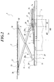
- FIG. 2 is a schematic side view of a luggage storage structure and the lifter of an automobile.
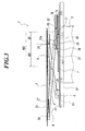
- FIG. 3 is the schematic side view of the luggage storage structure and the lifter of the automobile.
- FIG. 4 is the schematic side view of the luggage storage structure and the lifter of the automobile.
- FIG. 5 is a partially outside explanatory view of the luggage storage structure and the lifter of the automobile.
- FIG. 6 is a front sectional view of a rail frame.
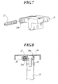
- FIG. 7 is an exploded perspective view of a slider.
- FIG. 8 is the front sectional view of a plate member frame.
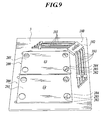
- FIG. 9 is the perspective view showing a lower surface of a plate member.
- FIG. 10 is an outside perspective view showing a table for supporting a plate member by a leg device for the table and a folding chair that is raised.
- the luggage storage structure and the lifter 2 of the automobile can transfer up and down a plate member 3 disposed in a luggage space 2a of the vehicle 1.
- the lifter 2 is not limited to the embodiment in which the lifter 2 is disposed in the vehicle 1.
- An embodiment is just one of various embodiments of the lifter 2.
- the plate member 3 approximately closes an upper part of a storage concave portion 5.
- the storage concave portion 5 is formed so as to project downward on a floor panel 4 of the vehicle 1. In other words, the plate member 3 is a bottom of the luggage space 2a when lowered.
- the plate member 3 opens the storage concave portion 5 while separating the luggage space 2a into an upper portion and a lower portion when raised.
- the vehicle 1 is a wagon type having the luggage space 2a rearward.
- the storage concave portion 5 is a spare-tire storage portion formed in the floor panel 4.
- a luggage is stored in the upper portion of the spare tire stored in a spare tire storage portion.
- the plate member 3 is formed as an approximately quadrangle and supported by a transfer mechanism 6 so as to transfer up and down.
- the transfer mechanism 6 is disposed in the floor panel 4.
- the transfer mechanism 6 has a pair of rail frames 7, a drive link 8 and a driven link 9.
- a pair of the rail frames 7 are fixed on the floor panel 4 side in parallel with each other.
- Each end of the drive link 8 and the driven link 9 is connected with the rail frame 7 side.
- the drive link 8 and the driven link 9 forms approximately an X-shape when the plate member 3 is transferred upward.
- the plate member frame 10 is disposed on a lower surface of the plate member 3.
- the other end side of each drive link 8 and each driven link 9 are respectively connected with the plate member frame 10.
- Each drive link 8 is connected with a lower slider 12 transferred along each rail frame 7 driven by a first electric motor 11.
- the drive link 8 and the driven link 9 are formed as a different length each other.
- the drive link 8 and the driven link 9 engage at an approximately middle position thereof so as to rotate each other.
- the plate member 3 transfers in a longitudinal direction in forward and rearward directions of the rail frame 7 while transferring up and down.
- each rail frame 7 extends forwardly and backwardly along the vehicle 1.
- a link member 13 extending in the horizontal direction links a front end side thereof.
- each rail frame 7 and the link member 13 are respectively fixed outside of the storage concave portion 5 of the floor panel 4.
- each rail frame 7 is fixed along a rear side member 14 disposed on a lower surface of the floor panel 4.
- the link member 13 is fixed along a rear cross member 15 disposed on the lower surface of the floor panel 4.
- a schematic structure of the luggage storage structure for the automobile and the lifter 2 was described as above. Hereinafter, the structure of the luggage storage structure and the lifter 2 are described in further details.
- the first electric motor 11 is connected with a lower slider 12 through a wire 16.
- One electric motor 11 disposed in the embodiment drives two lower sliders 12.
- the wire 16 is a conventional push-pull type of the wire 16.
- the wire 16 is connected with the inside of the right and left lower sliders 12.
- the first electric motor 11 and the wire 16 are a driving mechanism.
- the first electric motor 11 is disposed in the middle position of right and left link members 13.
- the lower slider 12 extends back and forth.
- the lower slider 12 is formed as approximately T-shape if seen from front.
- a lower position of the lower slider 12 is guided back and forth by a main rail 7a formed in the rail frame 7.
- the lower slider 12 is connected with one end side of the drive link 8 through an connecting link 17.
- a slide pin 18 extending right and left is disposed in the lower slider 12 side of the connecting link 17.
- a transfer guide groove 19 extending in a lengthwise direction of the vehicle 1 and penetrating the slide pin 18 is formed in the lower slider 12.
- a contacting surface 21 is formed in an upper portion of the lower slider 12. The contacting surface 21 upwardly slopes to the rearward of the vehicle 1 and contacts with a contacting portion 20 formed in the drive link 8.
- the connecting link 17 extending approximately in the lengthwise direction of the vehicle 1 is connected through a pivotal support pin 22 extending in a widthwise direction of the vehicle 1 to one end side of the drive link 8 so as to rotate.
- an approximately uprighted rail engage portion 22a is formed in the outside of the right and left pivotal support pin 22.
- the rail engage portion 22a is guided in the lengthwise direction of the vehicle 1 by a sub rail 7b formed in the rail frame 7. Further, the rail engage portion 22a is disposed in parallel with each rail frame 7.
- the rail engage portion 22a is guided in the longitudinal direction of the rail frame 7 by a right and left pair of sub rails 7b disposed in an upper portion of the rail frame 7.
- the sub rail 7b guides in the lengthwise direction of the vehicle 1 in the vicinity of a connecting portion.
- the portion is connected with the connecting link 17 in each drive link 8 through the rail engage portion 22a.
- the connecting link 17 is connected with the lower slider 12 and the drive link 8 when the connecting link 17 is upwardly sloped to the rearward of the vehicle 1.
- the lower slider 12 engages with the connecting link 17 of the drive link 8 side.
- the sub rail 7b is integrally formed with the rail frame 7.
- one end side of the connecting link 17 is connected with the lower slider 12 guided by the rail frame 7.
- the other end side is connected with the drive link 8 in an upper portion of the rail frame 7.
- the other end side is at the higher position than that of one end side, and as shown in FIGS. 2 to 4, the connecting link 17 is in the sloped state.
- the plate member 3 is relatively in a lower position while the drive link 8 is nearly in the horizontal state, the angle of the drive link 8 and the connecting link 17 is relatively large.
- the one end side of the drive link 8 is connected with the side of the rail frame 7 so as to transfer in the longitudinal direction of the rail frame 7. Further, the drive link 8 is connected with the side of the plate member 3 so as to transfer in the lengthwise direction of the vehicle 1.
- a first upper slider 23 can transfer in the lengthwise direction of the vehicle 1 by a rail portion 10a of the plate member frame 10. The first upper slider 23 is connected with the other end side of the drive link 8 so as to rotate.
- one end side of the drive link 8 can rotate with respect to the connecting link 17 by the pivotal support pin 22.
- the connecting link 17, the slide pin 18, the transfer guide groove 19 and the pivotal support pin 22 are a rotary connecting portion.
- predetermined interval is provided on the other end side than the pivotal support pin 22 so as to form a contacting portion 20 contacting with a contacting surface 21 of the lower slider 12.
- the contacting portion 20 is a pin-shaped member projected on the drive link 8.
- the drive link 8 and the driven link 9 are connected on the middle position therebetween so as to rotate.
- the drive link 8 is approximately horizontal when the plate member 3 closes the storage concave portion 5.
- the drive link 8 is raised when the plate member 3 transfers upward.
- one end side of each drive link 8 transfers along the rail frame 7 so as to shift each drive link 8 and each driven link 9 between the approximately horizontal state and the raised state.
- the rotary connecting portion has a transfer guide groove 19 extending in the longitudinal direction of the rail frame 7 and formed in the lower slider 12, and the connecting link 17 in which the slide pin 18 disposed on one end side is penetrated by the transfer guide groove 19 and the ether end side is connected with the other end side of the drive link 8 so as to rotate. Therefore, as shown in FIGS. 2 to 4, the slope angle of the connecting link 17 is constant in the embodiment.
- a transfer zone MS of the lower slider 12, as shown in FIGS. 2 to 4 includes an initial transfer zone IS in which the contacting surface 21 contacts with the contacting portion 20 so as to transmit a driving force of the lower slider 12 to the drive link 8, and a normal transfer zone RS in which the driving force is transmitted from the lower slider 12 through the connecting link 17, the slide pin 18 and the pivotal support pin 22 to the drive link 8. Therefore, in FIGS. 2 to 4, each MS, IS and RS zone is shown on the basis of an upper end portion 21a of the contacting surface 21 of the slider 12. In the embodiment, when the lower slider 12 transfers from the rearward to the forward of the rail frame 7, the drive link 8 is raised. In other words, the initial transfer zone IS and the normal transfer zone RS are arranged from the rearward to the forward of the rail frame 7.
- the above described rotary connecting portion is so structured that the slide pin 18 forming one end side of the connecting link 17 transfers in the groove 19 as the lower slider 12 transfers in the initial transfer zone IS, and one end side of the connecting link 17 positions at the end portion of the groove 19 as the lower slider 12 transfers in the normal transfer zone RS.
- the driving force of the lower slider 12 is not transmitted to the connecting link 17.
- one end side of the connecting link 17 positions to the rearward of the transfer guide groove 19 when the lower slider 12 passes the initial transfer zone IS and then transfers in the normal transfer zone RS the driving force of the lower slider 12 is transmitted to the connecting link 17.
- the driven link 9 is connected with the floor panel 4 side and the plate member frame 10 so as to rotate.
- one end side of the driven link 9 is connected with a pivotal support member 29 so as to rotate.
- the pivotal support member fixed to the floor panel 4.
- the other end side of the driven link 9 is so connected as to transfer in the lengthwise direction of the vehicle 1 with respect to the plate member frame 10.
- the other end side of the driven link 9 is connected with a second upper slider 24 so as to rotate.
- the second upper slider 24 can transfer back and forth by the rail portion 10a of the plate member frame 10.
- the driven link 9 as well as the drive link 8 is approximately horizontal when the plate member 3 closes the storage concave portion 5.
- the driven link 9 is raised when the plate member 3 transfers upward.
- the plate member frame 10 extends back and forth.
- the plate member frame 10 as well as the rail frame 7 is disposed on both right and left sides.
- a stiffening member 25 in which one end side thereof is extending approximately right and left is disposed in an upper portion of each rail frame 7 and links each plate member frame 10.
- a second electric motor 26 for transferring the first upper slider 23 along the rail portion 10a is disposed on the front lower side of the plate member frame 10.
- the second electric motor 26 is connected with a worm gear 27 extending approximately in the lengthwise direction of the vehicle 1.
- the second electric motor 26 and the worm gear 27 are a drive member.
- a screw hole 23a for screwing on the worm gear 27 is formed in the first upper slider 23.
- the screw hole 23a extending approximately in the lengthwise direction of the vehicle 1 forms a female screw portion on the inner surface.
- a penetrating hole for penetrating the worm gear 27 is formed in the second upper slider 24.
- the second electric motor 26 and the worm gear 27 are disposed on one side of the plate member frame 10.
- the drive link 8 and the driven link 9 connected with the other side of the plate member frame 10 have rollers 8a and 9a capable of rotating and transferring in the lengthwise direction of the vehicle 1.
- the plate member 3 and the plate member frame 10 are locked by a lock mechanism 28 disposed in the stiffening member 25.
- the lock of the lock mechanism 28 can be unlocked by a release portion 28a disposed on a lower surface of the plate member 3.
- the lock mechanism 28 is structured as well as conventional one, it is not herein described.
- a leg for a table 100 is disposed on the lower surface of the plate member 3.
- the leg for the table 100 provides an approximately horizontal support for the plate member 3.
- the table can be set up by using the plate member 3 as a top plate for the table and the leg for the table 100 as the leg for the table 100.
- the leg for the table 100 has a plurality of upper legs 101 for supporting the plate member 3, a link 102 connected with the upper leg 101 so as to rotate, and a plurality of lower legs 103 for supporting the link 102 so as to rotate.
- each upper leg 101 and each lower leg 103 sloped to rotate around the vertical direction with respect to the vertical direction as a center axis at the portion connected with the link 102.
- each lower leg 103 is rotated and transferred so as to choose a ground position of each lower leg 103. It is also applicable for an irregularity of a ground or the like.
- a folding chair 200 other than the leg device for the table 100 is fixed to the lower surface of the plate member 3.
- the folding chair 200 has a washer plate 201 fixed to the plate member 3 by screw or the like, and an approximately horseshoe-shaped front leg portion 202 and a rear leg portion 203 latched by the washer plate 201.
- the front leg portion 202 and the rear leg portion 203 are linked so as to rotate each other so that they are approximately overlapped each other in the folded state. Thereby, they are stored in the sitting plate 201.
- the front leg portion 202 and the rear leg portion 203 of the folded state can be rotated so as to unfold and then capable of being raised.
- an extendable remittent member 204 is bridged in the front leg portion 202 and the rear leg portion 203.
- the remittent member 204 is extended when the front leg portion 202 and the rear leg portion 203 are raised. Thereby, a passenger or the like can sit on the remittent member 204.
- the washer plate 201 can be latched in the top end of the front leg portion 202 and the rear leg portion 203 which are raised. Thereby, the passenger or the like can choose to sit on the remittent member 204 or sit on the washer plate 201.
- the passenger or the like of the automobile uses the plate member 3 as the bottom plate for the luggage space when the vehicle is driven.
- the passenger gets off the vehicle 1 at a destination, he can unfold the leg device for the table 100 and the folding chair 200 to use thereof as the table and a chair.
- the plate member 3 is fixed to each drive link 8 and each driven link 9 through the plate member frame 10.
- the passenger or the like can unlock the lock by using the release portion 28a so as to unlock the plate member 3 fixed to the plate member frame 10. Thereby he can remove the plate member 3 out of the vehicle side.
- the plate member 3 when the table and the chair are not used, the plate member 3 can be used as a bottom plate for the luggage space of the automobile. At this time, because the leg device for the table 100 and the folding chair 200 are fixed to a lower surface of the plate member 3 that is approximately horizontal, the space covered by the plate member 3 does not make the luggage space narrow and the relatively large luggage space is secured.
- the plate member 3 When the lower slider 12 positions at the rearward of the rail frame 7, the plate member 3 is in a lower position while the drive link 8 and the driven link 9 are approximately horizontal. Under the condition, when the first electric motor 11 is driven to transfer the lower slider 12 forward through the wire 16, the lower slider 12 transfers in the initial transfer zone IS and the normal transfer zone RS. Thereby, the plate member 3 transfers to the raised position.
- the contacting surface 21 of the lower slider 12 connects with the contacting portion 20 of the drive link 8. At this time, the contacting surface 21 of the lower slider 12 upwardly slopes to the rearward so as to transfer the contacting portion 20 upward as the lower slider 12 transfers forward.
- the drive link 8 is raised at the predetermined angle.
- the slide pin 18 connected with the connecting link 17 transfers comparatively rearward in the transfer guide groove 19 of the lower slider 12.
- the sub rail 7b guides the drive link 8 in the vicinity of the portion connected with the connecting link 17 to which the power of the lower slider 12 is transmitted, the driving force of the lower slider 12 can be effectively transmitted to the drive link.
- the slide pin 18 contacts with the back end of the transfer guide groove 19.
- the lower slider 12 and the side of the rail frame 7 of the drive link 8 integrally transfer forward.
- the lower slider 12 and the rail frame 7 side of the drive link 8 are connected by the connecting link 17, the slide pin 18 and the pivotal support pin 22 so as to rotate.
- the side of the rail frame 7 of the drive link 8 transfers as the lower slider 12 transfers.
- the plate member 3 side of the driven link 9 transfers in the same direction as the rail frame 7 side.
- Each drive link 8 and each driven link 9 are raised so as to form the approximately X-shape.
- the transfer of the plate member 3 to the raised position is finished.
- the plate member 3 transfers up and down while transferring in the longitudinal direction of the rail frame 7, the plate member 3 transfers in the way of tracking an approximately circular trajectory.
- the lower slider 12 and the drive link 8 are locked. Thereby, the plate member 3 is locked. In other words, the plate member 3 can be locked at a desired height.
- the plate member 3 transfers up and down while transferring in the longitudinal direction of the rail frame 7, the plate member 3 transfers in the way of tracking the approximately circular trajectory.
- the first electric motor 11 stops in the normal transfer zone RS
- the lower slider 12 and the drive link 8 are locked. Thereby, the plate member 3 is locked. In other words, the plate member 3 can be locked at the desired height.
- the second electric motor 26 is driven so as to transfer the plate member 3 in the lengthwise direction of the vehicle 1 with respect to each link 8 and 9.
- the worm gear 27 rotates.
- the first upper slider 23 screwing on the worm gear 27 is comparatively guided by the rail portion 10a.
- the plate member frame 10 and the plate member 3 transfer in the lengthwise direction of the vehicle 1 with respect to the first upper slider 23 linked by the drive link 8.
- the second upper slider 24 follows the first upper slider 23 so as to transfer in the lengthwise direction of the vehicle 1.
- the luggage stored in the storage concave portion 5 cannot be removed because the plate member 3 closes the storage concave portion 5.
- the thief or the like smashes the key hole of the vehicle 1 to intrude into the vehicle 1 for example, the luggage can be securely protected.
- the plate member 3 approximately completely covers the luggage, the luggage inside the vehicle can be kept secret.
- the luggage can be stored by using the usual spare tire storage portion formed in the floor panel 4. Further, by transferring the plate member 3 upward, the luggage can be mounted on both of the floor panel 4 side and the plate member 3. Because the luggage capacity of the luggage space 2 is increased, it is quite convenient for the practical use.
- each drive link 8 transfers in the longitudinal direction of the rail frame 7 so as to transfer the plate member 3 up and down
- the plate member 3 can be smoothly transferred up and down.
- two links of each drive link 8 and each driven link 9 can support the plate member 3 so as to stably support the plate member 3.
- the driving force of the lower slider 12 can be converted from the approximately horizontal direction to the approximately upper direction so as to be transmitted to the drive link 8 which is approximately horizontal.
- the driving force of the lower slider 12 can be converted from the approximately horizontal direction to the approximately upper direction so as to be transmitted to the drive link 8 which is approximately horizontal.
- the lower slider 12 passes the initial transfer zone IS and the drive link 8 is raised just at the predetermined angle, the lower slider 12 and the drive link 8 are connected, and the rail frame 7 side of the drive link 8 is transferred with the lower slider 12 in the approximately horizontal direction. Thereby, the drive link 8 can be raised more higher.
- the driving force of the lower slider 12 is transmitted to the drive link 8 side through the connecting link 17 extending approximately in the lengthwise direction of the vehicle 1.
- one end side of the drive link 8 can be disposed more rearwardly.
- the drive link 8 is structured longer so as to make the vertical stroke of the plate member 3 larger.
- the sub rail 7b of the rail frame 7 guides the pivotal support pin 22 so as to stably transfer the drive link 8.
- the lower slider 12 is stably transferred by the first electric motor 11 so as to smoothly transfer the plate member 3 up and down. Further, the first electric motor 11 is stopped so as to lock the plate member 3.
- the first electric motor 11 may be so driven that the plate member 3 is lowered and contacts with the upper portion of the luggage, and when the predetermined force is applied from the plate member 3 to the luggage, the first electric motor 11 is stopped so as to fix the luggage.
- the plate member 3 can be transferred in the lengthwise direction of the vehicle 1 with respect to each drive link 8 and each driven link 9.
- the passenger or the like can transfer the plate member 3 in accordance with usages or the like.
- the passenger or the like can drive the second electric motor 26 so as to transfer the plate member in front of him or her (for example, backdoor side) to handle the luggage.
- the plate member 3 is disposed on the plate member frame 10 so as to be removed. Thereby, the passenger or the like can use the plate member 3 not only for approximately closing the storage concave portion 5 but also for removing the plate member 3 out of the vehicle 1 side to use as a top panel of the table outside the vehicle 1.
- each rail frame 7 is disposed along the rear side member 14 of vehicle 1
- the load applied by each link 8 and 9 effects the rear side member 14 so as to prevent the floor panel 4 from deformation.
- the luggage capacity of the plate member 3 effectively increases.
- the link member 13 is disposed along the rear cross member 15, the deformation of the floor panel 4 can be prevented and more large amount of the luggage can be mounted on the plate member 3.
- the lifter 2 of the embodiment because the plate member 3 transfers in the lengthwise direction of the vehicle 1 while transferring up and down, the plate member 3 can be transferred not only up and down but in the horizontal direction so as to enhance transfer flexibility of the plate member 3.
- the lifter 2 can be disposed by approximately coinciding with a transfer trajectory of the plate member 3 along an upper portion of the space.
- the luggage or the like can be transferred by the lifter 2 by configuring the transfer trajectory of the plate member on the basis of the slope angle of the side wall or the like.
- the lower slider 12 transferring along the rail frame 7 transfers one end side of each drive link 8 so as to smoothly transfer the plate member 3 up and down.
- the driving force of the lower slider 12 can be converted from the approximately horizontal direction to the approximately upper direction so as to be transmitted to the drive link 8 which is approximately horizontal.
- the driving force of the lower slider 12 can be converted from the approximately horizontal direction to the approximately upper direction so as to be transmitted to the drive link 8 which is approximately horizontal.
- the lower slider 12 passes the initial transfer zone IS and the drive link 8 is raised at the predetermined angle, the lower slider 12 and the drive link 8 are connected so as to rotate. Thereby, the rail frame 7 side of the drive link 8 and the lower slider 12 are transferred in the approximately horizontal direction and the drive link 8 can be raised more higher.
- the slide pin 18 of one end side of the connecting link 17 is penetrated in the transfer guide groove 19 formed in the lower slider 12, and thereby with a simple structure, because the transmission of the driving force from the lower slider 12 to the connecting link 17 can be converted, the luggage storage structure is quite convenient for the practical use.
- the drive link 8 is guided by the sub rail 7b in the vicinity of the portion connected with the connecting link 17 to which the power of the lower slider 12 is transmitted, the driving force of the lower slider 12 can be effectively transmitted to the drive link 8 so as to precisely transfer the plate member 3 up and down.
- the angle of the drive link 8 and the connecting link 17 is approximately large so as to transfer the drive link 8 to the raised state side by using relatively small power.
- the lower slider 12 is stably transferred by the first electric motor 11 so as to smoothly transfer the plate member 3 up and down. Further, the first electric motor 11 is stopped so as to lock the plate member 3.
- the plate member 3 can transfer in the lengthwise direction of the vehicle 1 with respect to each drive link 8 and each driven link 9 by driving the second electric motor 26.
- the user of the lifter or the like can transfer the plate member 3 in accordance with the usage or the like.
- the user of the lifter or the like can take the luggage by driving the second electric motor 26 so as to transfer the plate member 3 to an user side (for example, backdoor side).
- the driving force of the lower slider 12 is transmitted to the drive link 8 side through the connecting link 17 extending approximately in the lengthwise direction of the vehicle 1.
- one end side of the drive link 8 can be disposed more rearwardly.
- the drive link 8 is structured more longer so as to make the vertical stroke of the plate member 3 larger.
- the sub rail 7b of the rail frame 7 guides the pivotal support pin 22 so as to stably transfer the drive link 8.
- the plate member 3 is disposed on the plate member frame 10 so as to be removed. Thereby, the driver or the like can use the plate member 3 not only for approximately closing the storage concave portion 5 but for removing the plate member 3 out of the vehicle 1 side to use as a top panel of the table outside the vehicle 1.
- the second upper slider 24 may be driven.
- the first upper slider 23 is structured to freely transfer in the lengthwise direction of the vehicle 1
- the second upper slider 24 can transfer in the lengthwise direction of the vehicle 1 by driving the second electric motor 26.
- the plate member 3 is transferred in the lengthwise direction of the vehicle 1.
- the second electric motor 26 disposed on the plate member frame 10 is shown, it goes without saying that the second electric motor 26 may be disposed on the stiffening member 25. In this case, as well as the first electric motor 11, it is preferable that the second electric motor 26 is connected to the first upper slider 23 through the push-pull type wire.
- the plate member 3 and the plate member frame 10 transferred in the lengthwise direction of the vehicle 1 with respect to each link 8 and 9 by the second electric motor 26 are shown, for example, the plate member frame 10 may be transferred right and left.
- first upper slider 23 and the second upper slider 24 may be driven together by the second electric motor 26.
- the screw spiral is inverted on the first upper slider 23 side and the second upper slider 24 side so as to screw the worm gear 27 on the second upper slider 24. Therefore, each slider 23 and 24 approach or separate each other by driving the second electric motor 26.
- the drive link 8 and the driven link 9 can be shifted to the raised state or the approximately horizontal state. Therefore, the first electric motor 11 and the second electric motor 26 can be synchronized so that each first electric motor 11 and 26 can cooperate. Thereby, the plate member 3 can be transferred up and down so as to reduce the load of the first electric motor 11.
- the second electric motor 26 is supplementarily driven so as to shift the drive link 8 from the approximately horizontal state to the raised state of the predetermined angle.
- the pivotal support pin 22 of the drive link 8 is penetrated direct through the transfer guide groove 19 of the lower slider 12.
- the sub rail 7b guiding the pivotal support pin 22 in the lengthwise direction of the vehicle 1 can be removed.
- each right and left lower sliders 12 transferred by one first electric motor 11 may be separately driven by two electric motors 11, 26.
- each lower slider 12 is separately controlled so as to reduce the load of each electric motor 11 or 26.
- the luggage capacity of the plate member increases.
- the output torque of each electric motor 11 or 26 can be changed in accordance with the weight distribution applied from the plate member 3 to each right and left links 8 and 9 in the case of that the luggage is not equally mounted on the right and left sides of the plate member 3.
- the wire 16 transferring the lower slider 12 is shown, as well as the first upper slider 23, the worm gear 27 may transfer the lower slider 12.
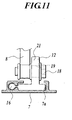
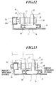
- the wire 16 is connected with the inside of the right and left lower sliders 12, as shown in FIG. 11, the wire 16 may be connected with the outside of the right and left lower sliders 12.
- the wire 16 is connected on both right and left sides of the lower slider 12.
- the lower slider 12 can be approximately equally pushed and pulled on the right and left sides. Thereby, the moment caused in the lower slider 12 or the like is reduced, and the endurance, the credibility or the like thereof is enhanced.
- the wire 16 may also be connected with the pivotal support pin 22.
- the lower slider 12 when a point of the force applied from the wire 16 connected with the pivotal support pin 22 to the drive link 8 is symmetrical to one from the lower slider 12 thereto, the lower slider 12 can be more stably pushed and pulled.
- the driving member having the first electric motor 11 may have a biasing force such as a gas stay, a spring and a hydraulic circuit or the like.
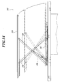
- the gas stay 100 is used as the driving member.
- the lifter 101 shown in FIG. 14 as well as the embodiment also has a pair of rail frames 107 which is disposed in the predetermined flat surface and which is parallel to each other, and the drive link 8 and the driven link 9 which are connected with the plate member 103 side and the rail frame 107 side. In this case, by assuming that the drive link 108 and the driven link 109 are different each other in length, the plate member 103 transfers in the longitudinal direction of the rail frame 107 while transferring up and down.
- the storage concave portion 5 formed as a spare tire storage portion for adjusting the luggage space 2a is shown, the storage concave portion 5 is not limited to this configuration, and may be formed to project downward on the floor panel 4, for example, formed as a passenger compartment or the like on the middle side of vehicle 1. Other features or the like can be accordingly modified in details.
- the lifter 2 of the present invention disposed in the vehicle 1 is shown, as described above, for example, even if the lifter 2 is disposed in the narrow space such as the loft of the house sloped in the upper position, the same efficiency as the embodiment can be obtained. Also, the other features or the like can be accordingly modified in details.
- FIGS. 15 to 19 show a second embodiment of the present invention.
- FIG. 15 is an externally perspective view inside the vehicle.
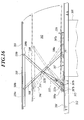
- FIG. 16 is a side view of the luggage storage structure of an automobile.
- FIG. 17 is a plan view of the luggage storage structure of an automobile.
- FIG. 18 is a front sectional view of the plate member frame.
- FIG. 19 is a side sectional view in the vicinity of the aperture which is formed on the plate member for grasping by hand.
- the luggage storage structure for this automobile transfers approximately up and down a plate member 303 disposed in a luggage space 302 of the vehicle 301.
- the plate member 303 approximately closes an upper part of a storage concave portion 305 formed so as to project downward on a floor panel 304.
- the plate member 303 is a bottom of the luggage space 302 when being lowered.
- the plate member 303 opens the storage concave portion 305 and approximately separates the luggage space 302 into the upper portion and the lower portion when raised.
- the vehicle 301 is a wagon having the luggage space 302 rearward.
- the storage concave portion 305 is an approximately circular spare tire storage portion formed in the floor panel 304. In other words, the luggage is stored in the upper portion of the spare tire stored in the spare tire storage portion.
- the plate member 303 is formed approximately quadrangle and supported by the transfer mechanism 306 so as to transfer approximately up and down.
- the transfer mechanism 306 is disposed in the floor panel 304.
- this transfer mechanism 306 has a pair of rail frames 307 fixed on the floor panel 304 side and approximately parallel each other, and a main link 308 and a driven link 309.
- One end side of the main link 308 and the driven link 309 is respectively connected with the rail frame 307, and the main link 308 and the driven link 309 form the approximately X-shape when the plate member 303 is transferred upward.
- a plate member frame 310 is disposed on a lower surface of the plate member 303.
- Each main link 308 and each driven link 309 are respectively connected with the plate member frame 310.
- Each rail frame 307 extends in the lengthwise direction of the vehicle 1 and the front end side thereof is linked with a link 311 extending right and left.
- each rail frame 307 and the link 311 are respectively fixed outside the storage concave portion 305 of the floor panel 304.
- Each rail frame 307 is fixed along a rear side member 312 disposed on a lower surface of the floor panel 304.
- the link 311 is fixed along a rear cross member 313 disposed on a lower surface of the floor panel 304.
- each rail frame 307 has a transfer guide groove 307a penetrating a transfer pin 308a.
- the transfer pin 308a is formed on one end side of the main link 308 and extends approximately right and left.
- the transfer guide groove 307a is formed so as to extend in the lengthwise direction of the vehicle 1 in the rearward of the rail frame 307.
- the transfer pin 308a can transfer in the lengthwise direction of the vehicle 1.
- each rail frame 307 has a rotating aperture 307b penetrating a rotating pin 309a.
- the rotating pin 309a is formed on one end side of the driven link 309 and extends approximately right and left.
- the rotating aperture 307b is formed in a front position of the rail frame 307. The rotating pin 9a can rotate around the rotating aperture 307b.
- a plate member frame 310 extends in the lengthwise direction of the vehicle 1, and is respectively disposed on both right and left sides.
- Each plate member frame 310 is disposed in an upper portion of each rail frame 307, and one end side of each plate member frame 310 is linked by a stiffening member 310c extending approximately right and left.
- each plate member frame 310 has a transfer guide groove 310a penetrating a transfer pin 308b.
- the transfer pin 308b is formed on the other side of the main link 308 and extends approximately right and left.
- the transfer guide groove 310a is formed so as to extend back and forth in a front position of the plate member frame 310.
- the transfer pin 308b can transfer in the lengthwise direction of the vehicle 1.
- each plate member frame 310 has a rotating aperture 310b penetrating a rotating pin 309b.
- the rotating pin 309b is formed on the other end side of the driven link 309 and extends approximately right and left.
- the rotating aperture 310b is formed in the rearward of the plate member frame 310.
- the rotating pin 309b can rotate around the rotating aperture 310b.
- both end sides of each main link 308 are respectively connected with the rail frame 307 and the plate member frame 310 so as to transfer in the lengthwise direction of the vehicle 1.
- both end sides of each driven link 309 are respectively connected with the rail frame 307 and the plate member frame 310 so as to rotate.
- the middle sides of each main link 308 and each driven link 309 are connected each other so as to rotate.
- each main link 308 is raised.
- each driven link 309 is connected with each main link 308 so as to rotate, each main link 308 and each driven link 309 are raised together. Further, because each link 308 and 309 is raised, as shown in FIG. 16, the plate member 303 is transferred upward.
- each main link 308 is approximately horizontal and each driven link 309 is approximately horizontal.
- the plate member 303 is lowered.
- the transfer trajectory of the plate member 303 is approximately circular shape along the backdoor or the like.
- each main link 308 and each driven link 309 are linked through a rotating pin member 314.
- This rotating pin member 314 is connected with a gas stay 315, and one end thereof is connected with the rail frame 307.
- the gas stay 315 can extend and contract, and provides a biasing force in the extending direction.
- the gas stay 315 extends and contracts between the plate member 303 and each rail frame 307.
- the inner structure of the gas stay 315 is not described because it is the same structure as a conventional one.
- a rotating pin 315a extending approximately right and left is formed on one end side of the gas stay 315.
- This rotating pin 315a is structured so as to penetrate the rotating aperture 307c of the rail frame 307.
- This rotating aperture 307c is formed in a front position of the rail frame 307.
- the rotating pin 315a can rotate around the rotating aperture 307c.
- a pin aperture 315b penetrating the rotating pin member 314 is formed on the other end side of the gas stay 315.
- the gas stay 315 together with each main link 308 and each driven link 309 are raised and approximately horizontal.
- this rotating aperture 307c is formed in the rear side of the rotating aperture 307b of the driven link 309. Thereby, as shown in FIG.
- the gas stay 315 that is approximately horizontal is gradually raised as the plate member 303 transfers upward.
- the gas stay 315 has the biasing force of the extending direction
- the upward biasing force increases as the angle between the gas stay 315 and the plate member 303 increases.
- the biasing force of the gas stay 315 increases as the plate member 303 is raised, the plate member 303 is slowly raised when opening the storage concave portion 305 and the plate member 303 is stably raised after transferring at the predetermined height.
- the biasing force is applied to the approximately horizontal direction. In other words, when the plate member 303 approximately closes the storage concave portion 305, the biasing force of the gas stay 315 is not applied upward at all.
- a spring member 316 is disposed in each rail frame 307 and biases upward the plate member 303 approximately closing the storage concave portion 305.
- the biasing force of the spring member 316 as an initial biasing member is applied to the plate member 303 side.
- the plate member 303 is transferred upward by the spring member 316.
- the plate member 303 is transferred upward by the biasing force of the gas stay 315.
- the biasing force of the gas stay 315 is not applied upward to the plate member 303 side at all.
- the plate member 303 can be raised by the spring member 316 to the position where the biasing force of the gas stay 315 is applied.
- a lock mechanism 317 disposed on the plate member frame 310 side locks the plate member 303 at the position where the storage concave portion 305 is approximately closed, and capable of locking the plate member 303 at the multistage vertical position.
- the lock mechanism 317 has a lock plate 317a, a rod 317b and a lever 317c.
- the lock plate 317a is disposed inside the right and left main links 308 and can transfer approximately right and left.
- the rod 317b contacts with this lock plate 317a and transfers the right and left lock plates 317a to the inside each other.
- the lever 317c is connected with the rod 317b.
- the lock plate 317a is disposed along the transfer guide groove 310a of the plate member frame 310.
- a notch 317d capable of receiving the end of the transfer pin 308a is juxtaposed in the lengthwise direction of the vehicle 1.
- the lock plate 317a is biased on the transfer pin 308a side. Because the transfer pin 308a engaging the notch 317d is not released unless the right and left lock plates 317a is transferred to the inside each other, the driven link 308 cannot transfer.
- the notch 317d is formed with respect to the position where the plate member 303 can approximately close the storage concave portion 305, the position where the plate member 303 is completely raised and the middle position thereof.
- the lock mechanism 317 functions as a closing mechanism and a positioning mechanism.
- the closing mechanism locks the plate member 303 at the position where the plate member 303 can approximately close the upper part of the storage concave portion 305.
- the positioning mechanism can lock the plate member 303 at the multistage vertical position.
- the rod 317b extends and can transfer in the lengthwise direction of the vehicle 1. As the rod 317b transfers forward, the front end side thereof contact with the lock plate 317a and the right and left lock plates 317a transfer to the inside each other.
- the lever 317c is connected through a plurality of links with the rear end side of the rod 317b.
- the lever 317c is disposed inside the aperture 303a formed in the plate member 303 and grasped by the hand. As shown in FIG. 19, the lever 317c can rotate with respect to the plate member 303. By rotating the lever 317c so as to project from the plate member 303, the rod 317b transfers forward.
- the lever 317c is a height-adjustable operating portion capable of unlocking.
- the plate member 303 and the plate member frame 310 are locked by a fixing portion 318 disposed in the stiffening member 310c.
- the lock of the fixing portion 318 can be unlocked by the operating portion 318a disposed on a lower surface of the plate member 303.
- the leg device 100 for the table and the folding chair 200 according to the first embodiment can be also disposed on the lower surface of the plate member 303 like the first embodiment.
- the description of the leg device for table and the folding chair is omitted.
- the storage concave portion 305 is approximately closed by the plate member 303.
- the luggage can be stored in the storage concave portion 305 by transferring the plate member 303 upward.
- the plate member 303 is locked by the lock mechanism 317 when approximately closing the storage concave portion 305.
- the lock mechanism 317 is unlocked, the plate member 303 is transferred upward by the biasing force of the gas stay 315.
- the gas stay 315 smoothly extends, the plate member 303 cannot be suddenly moved when the lock mechanism 317 is unlocked.
- each main link 308 and each driven link 309 form the approximately X-shape and are raised.
- the plate member 303 transfers upward, and thereby the plate member 303 approximately separates the luggage space 302 into the upper portion and the lower portion.
- the luggage can be mounted not only on the floor panel 304 side such as the storage concave portion but also on the plate member 303 side.
- the plate member 303 that was biased upward can be locked at each of the predetermined vertical position. Therefore, in accordance with the size of the luggage stored in the luggage space 302, the vertical position of the plate member 303 can be adjusted and the vertical separating position of the luggage space 302 can be easily adjusted. Further, adjusted the height of the plate member 303, the user uses the lever 317c disposed inside the aperture so as to unlock the plate member 3 from the positioning mechanism 317 and transfer the plate member 303. Here, because the lever 317c is disposed inside the aperture, the luggage mounted on the plate member 303 cannot contact with the lever 317c.
- each main link 308 and each driven link 309 are approximately horizontal by transferring one end side of each main link 308 from the other end side of each rail frame 307 to one end side thereof.
- the user can grasp the aperture 303a which is formed on the plate member 303 and grasped by hand, and transfer the plate member 303. Further, because the plate member 303 is removable from each main link 308 side and each driven link 309 side, the user can grasp the aperture 303a so as to transfer the plate member 303 separated from each link 308 and 309.
- the luggage stored in the storage concave portion 305 cannot be reached because the storage concave portion 305 is approximately closed by the plate member 303. Further, the luggage is reliably hidden by the plate member 303 so as to keep the luggage secret inside the vehicle 1.
- the luggage can be stored by using the common spare tire storage portion formed in the floor panel 304. Further, the luggage can be mounted on both of the floor panel 304 side and the plate member 303 side. Thereby, because the capacity of the luggage space 302 is additionally increased, the luggage storage is quite convenient for the practical use.
- both end sides of each main link 308 transfer in the longitudinal direction of the rail frame 307 so that the plate member 303 transfers up and down.
- the plate member 303 can be smoothly transferred up and down.
- the plate member 303 can be supported by two links of each main link 308 and each driven link 309 so as to stably support the plate member 303.
- the luggage storage structure of this embodiment because the plate member 303 can be handled by using the aperture 303a, the luggage storage structure additionally enhances the convenience for usages. Further, because the lever 317c is disposed inside the aperture 303a, the luggage cannot contact with the lever 317c nor unlock the lock. Thereby, the lock mechanism 317 can securely lock the plate member 303.
- the plate member 303 can be smoothly transferred up and down by the gas stay 315 so that the user can reliably transfer the plate member 303. Further, because the plate member 303 cannot be suddenly moved, an excess load or the like does not occur in the transfer mechanism 306 or the like. Thereby, the reliability and the durability of the transfer mechanism 306 can be additionally enhanced.
- the plate member 303 is structured so as to be removed with respect to the plate member frame 310, the user can remove the plate member 303 out of the vehicle 1 and use it for example as a top plate for the table. Thereby, the plate member 303 can be used for other purposes than those of approximately closing the storage concave portion 305.
- the lever 317c is disposed inside the aperture 303a that can be grasped by the hand, when the storage concave portion 305 is approximately closed, the fixation between the plate member 303 and the plate member frame 310 cannot be unlocked. Thereby, for example by removing the key of the automobile and setting the close locking mechanism 317 make it impossible to be unlocked, even when the thief or the like smashes the key to the vehicle 1 and sneaks inside the vehicle 1, the luggage stored in the storage concave portion 305 can be reliably secured.
- each rail frame 307 is disposed along the rear side member 312 of vehicle body, the load applied from each link 308 and 309 is applied to the rear side member 312 so as to prevent the floor panel 304 from deformation and effectively increase the luggage capacity of the plate member 303.
- the link member 311 is disposed along the rear cross member 313, which also prevents the floor panel 304 from deformation and increases the luggage capacity of the plate member 303.
- the plate member 303 side is biased upward by the gas stay 315
- the plate member 303 may be biased upward by the elastic body such as the spring.
- the gas stay 315 may be connected for example with the plate member frame 310. Any kinds of the structure may be used to bias the plate member 303 upward.
- the storage concave portion 305 is a spare tire storage portion formed so as to meet the luggage space 302
- the storage concave portion 305 is not limited to this configuration.
- the storage concave portion 305 may be formed to project downward on the floor panel 304 for example formed in the passenger space of the middle side of vehicle 1.
- lock mechanism 317 functions as the locking and positioning mechanism
- two lock mechanisms may be used so as to cope with each mechanism.
- the height adjustable operating portion is a rotatable lever 317c
- the height adjustable operating portion may be a button for unlocking the lock mechanism 317 by pushing thereon.
- other features can be accordingly modified in details.
Landscapes
- Engineering & Computer Science (AREA)
- Mechanical Engineering (AREA)
- Life Sciences & Earth Sciences (AREA)
- Geology (AREA)
- Structural Engineering (AREA)
- Chemical & Material Sciences (AREA)
- Combustion & Propulsion (AREA)
- Transportation (AREA)
- Vehicle Step Arrangements And Article Storage (AREA)
Abstract
Description
- The present invention relates to a luggage storage structure for an automobile for storing a luggage in a storage concave portion formed in a floor panel, and a lifter for transferring a plate member for the luggage at least upwardly and downwardly.
- Heretofore, as this type of luggage storage structure for an automobile, it is known that a tray for storing a luggage is disposed in a storage concave portion formed in a floor panel (e.g. JP-A-2002-240634).
- The tray is structured so as to extend and contract in a horizontal direction and a length of the horizontal direction is changed in accordance with usage purposes. In this kind of the luggage storage structure, an upper part of the storage concave portion is open and the luggage is mounted and removed in any directions as required on the tray at any time.
- However, in the above luggage storage structure for the automobile, because the luggage on the tray is exposed inside the vehicle, the luggage or the like is visible from outside of the vehicle. In other words, the luggage storage structure cannot keep the luggage secret.
- Moreover, when a thief or the like smashes the key and sneaks to the vehicle, the exposed luggage cannot be secured.
- Heretofore, a known lifter of an earlier development transfers two links respectively from and to a horizontal state to/from a raised state so as to raise and lower the plate member with respect to the predetermined surface. The two links are connected to a lower position of the plate member on which the luggage is mounted. The two links are connected so as to rotate and form an X-shape. (JP-A-9-290995).
- Each link is formed as the same length and linked each other at the middle point in a longitudinal direction. One end side of one link is connected with the plate member so as to rotate, and the other end is connected with the predetermined surface side so as to transfer in the horizontal direction. Further, one end side of the other link is connected with the predetermined surface side so as to rotate. The other end side is connected with the plate member so as to transfer in the horizontal direction. Each link is driven so as to transfer appropriately from and to the approximately horizontal state to and from the approximately raised state by a driving member. In the lifter, each link having the same length is linked so as to rotate at the middle point in the longitudinal direction each other, and the plate member transfers upwardly and downwardly.
- In the above lifter, however, because the plate member transfers just upwardly and downwardly, the lifter cannot be disposed therein unless the vertical stroke of the plate member is secured. In other words, the lifter has a drawback of being unavailable, for example, in a narrow space sloped in an upper position, such as a loft of a house and a trunk room of the automobile.
- In addition, when the luggage is transferred between the stepped lower horizontal surface and the stepped upper horizontal surface, the lifter is disposed on the horizontal surface of a lower position. In this case, however, a constraint requires forming an approximately perpendicular sidewall between the lower horizontal surface and the upper horizontal surface. In other words, for example, if the middle portion of the sidewall slopes at more than or equal to 90° so as to obliquely project, the projecting portion interferes the plate member. On the other hand, if the upper part of the side wall slopes at less than or equal to 90° , a gap occurs between the upper horizontal surface and the plate member when the plate member is transferred upwardly. Both cases undermine a transfer capability for the luggage.
- Like this, because the transfer direction of the plate member is limited to just upwardly and downwardly, the lifter is quite inconvenient for practical uses.
- The present invention has been made in view of above points. An object of the present invention is to provide a luggage storage structure for an automobile capable of reliably securing the luggage stored in a storage concave portion.
- Another object of the present invention is to enhance the transfer flexibility of a plate member by transferring the plate member not only in the vertical direction but in the horizontal direction.
- In order to solve the above problems, in accordance with a first aspect of the present invention, a luggage storage structure for vehicle, comprising:
- a storage concave portion formed to project downward on a floor panel;
- a plate member for closing an upper part of the storage concave portion; and
- a transfer mechanism for transferring the plate member up and down in an upper part of the floor panel.
- a pair of rail frames fixed on a floor panel side and being parallel to each other;
- a pair of drive links, one end side of the drive links being connected with a rail frame side so as to transfer in a longitudinal direction of the rail frame, the other end side being connected with a plate member side, the drive links being horizontal when the plate member closes the storage concave portion, and the drive links being raised when the plate member is transferred upward;
- a pair of driven links, both end sides of the driven links being connected with the plate member side and the floor panel side, a middle side of the driven links being connected with the drive link so as to rotate, the driven links being horizontal when the plate member closes the storage concave portion and the driven links being raised when the plate member is transferred upward;
- a plurality of sliders capable of transferring in the longitudinal direction of the rail frame, the sliders engaging with a drive link side; and
- a driving mechanism for transferring each slider in the longitudinal direction of the rail frame; wherein each drive link and each driven link shift between an approximately horizontal state and a raised state by transferring one end side of each drive link along the rail frame.
-
- According to the first aspect of the present invention, in addition to the above function, when the driving member is driven and each slider is transferred in one of the longitudinal directions of the rail frame, one end side of each drive link integrally transfers with each slider. Thereby, each drive link and each driven link form an approximately X-shape and are raised.
- Likewise, when the driving member is driven so as to transfer each slider in the other direction of the longitudinal direction of the rail frame, one end side of each drive link integrally transfers with each slider. Thereby, each drive link and each driven link are approximately horizontal.
- Therefore, because the plate member is transferred upwardly and downwardly by transferring one end side of each drive link in the longitudinal direction of the rail frame, the plate member can be smoothly transferred upwardly and downwardly. Further, two links of each drive link and each driven link can support the plate member so as to stably support the plate member.
- According to the present invention, the storage concave portion is approximately closed by the plate member. The luggage can be stored in the storage concave portion by transferring the plate member upwardly.
- Therefore, the luggage stored in the storage concave portion cannot be removed because the storage concave portion is approximately closed by the plate member. In other words, when a thief or the like smashes a key and sneaks to the vehicle for example, the luggage can be reliably secured. Further, because the luggage is approximately reliably covered by the plate member, the luggage can be kept secret in the vehicle.
- Preferably, the storage concave portion is a spare tire storage portion, the plate member transferring approximately up and down in a luggage space of said vehicle.
- According to the present invention, in addition to the above function, the luggage is stored in an upper part of the spare tire stored in the spare-tire storage portion. Further, because the plate member transfers upwardly, the plate member approximately separates the luggage space into the upper portion and the lower portion. At this time, the luggage can be mounted on the plate member as well as the floor panel side such as the storage concave portion.
- Therefore, an old spare-tire storage portion of prior arts formed on the floor panel is used so as to store the luggage. Further, by transferring the plate member upwardly, the luggage can be mounted on both of the floor panel side and the plate member. Because the luggage capacity of the luggage space is additionally increased, the luggage storage structure is convenient for the practical use.
- Preferably, the luggage storage structure further comprising:
- a contacting portion capable of contacting with the slider side, is formed on the rail frame side of each drive link;
- a contacting surface sloped upward in a transfer direction of the slider and contacted with the contacting portion when the drive link is raised from the horizontal state, and
- a rotary connecting portion capable of connecting with the rail frame side of the drive link so as to rotate,
- an initial transfer zone of the contacting portion for contacting with the contacting surface so as to transmit a driving force of the slider to the drive links; and
- a normal transfer zone provided for the driving force to be transmitted from the slider through the rotary connecting portion to the drive links.
-
- According to the present invention, in addition to the above function, when the plate member is approximately closing the storage concave portion and the drive link is approximately horizontal and when the driving member is driven so as to transfer the slider, this slider transfers in an initial transfer zone and a normal transfer zone, and the plate member is transferred to the upward position.
- When the slider transfers in the initial transfer zone, the contacting surface of the slider contacts with the contacting portion of the drive link. At this time, the contacting surface of the slider is sloped upward in the transfer direction. Thereby, the contacting portion is raised as the slider transfers. The slider passes the initial transfer zone, before the drive link is raised to the predetermined angle.
- Further, when the slider transfers in the normal transfer zone, the rotary connecting portion of the slider is connected with the rail frame side of the drive link so as to rotate. Thereby, the rail frame side of the drive link transfers as the slider is transferring and the plate member side of the drive link transfers in the opposite direction of the rail frame side. Each driving and driven links form the approximately X-shape and is raised.
- Therefore, in the initial transfer zone, the driving force of the slider is converted from the approximately horizontal direction to the approximately upward so as to transmit an approximately upward force to the drive link which is approximately horizontal. At this time, without a link mechanism or the like for example, a direct contact between the drive link and the slider transmits the driving force. Thereby, the space for the link mechanism or the like is not necessary between the rail frame and the plate member.
- Further, when the slider passes the initial transfer zone and the drive link is raised just at the predetermined angle, the rotary connecting portion and the driving rink are connected, and the rail frame side of the drive link is transferred with the slider in the approximately horizontal direction. Thereby, the drive link can be raised more higher.
- Preferably, the luggage storage structure further comprising:
- an electric motor in the driving mechanism, wherein:
- two electric motors are disposed, and each slider is independently driven by each electric motor..
-
- According to the present invention, in addition to the above function, the slider can be stably transferred by the electric motor so as to smoothly transfer the plate member upwardly and downwardly.
- Further, each slider is separately controlled so as to reduce the load of each electric motor and increase the luggage capacity of the plate member.
- Further, when the luggage is lopsidedly or inclinedly mounted on the plate member and so forth, the output torque of each electric motor can be changed on the basis of the weight distribution applied from the plate member to each right or left links.
- Preferably, the luggage storage structure further comprising:
- a plate member frame for supporting the plate member, the plate member frame being connected with each drive link and each driven link, and the plate member frame transferring in a predetermined direction with respect to each drive link and each driven link; and
- a driving member for transferring the plate member frame in the predetermined direction.
-
- According to the present invention, in addition to the above function, the driving member is driven so as to transfer the plate member and frame in the predetermined direction with respect to each drive link and each driven link.
- Therefore, a passenger can transfer the plate member in accordance with usages. For example, when the luggage mounted on the plate member is taken out from the vehicle or when the luggage taken out from the vehicle is mounted on the plate member, the driving member is driven so that the passenger can transfer the plate member in front of him or her to handle the luggage.
- Preferably, the luggage storage structure further comprising:
- a plate member frame for supporting the plate member, the plate member frame being connected with each drive link and each driven link;
- a lock portion for locking the plate member and the plate member frame; and
- a lock mechanism having an operating portion capable of unlocking the lock portion, the operating portion of the lock mechanism being disposed on a lower surface of the plate member.
-
- According to the present invention, in addition to the above function, the plate member is fixed through the plate member frame to each driving or driven link. A passenger can unlock the fixation between the plate member and the plate member frame and take the plate member out of the vehicle by using the operating portion for unlocking the lock.
- Here, when the plate member is approximately closing the storage concave portion, the passenger cannot reach inside the storage concave portion nor operate the operating portion disposed on the lower surface of the plate member. In other words, when the plate member is transferred upward, the plate member is unlocked.
- Therefore, the passenger can use the plate member for not only approximately closing the storage concave portion but also removing the plate member outside the vehicle to use it as a top panel of a table or the like.
- Further, when the storage concave portion is approximately closed, the fixation between the plate member and frame cannot be unlocked. For example, by removing the key of the vehicle and setting the closed locking mechanism impossible to be unlocked, even when a thief or the like smashes or breaks the key and sneaks inside the vehicle, the luggage stored in the storage concave portion can be reliably secured.
- In accordance with a second aspect of the present invention, a luggage storage structure for an automobile, comprises: a storage concave portion formed so as to project downward on a floor panel and capable of storing the luggage; a closed locking mechanism for locking the plate member at the position where an upper part of the storage concave portion is approximately closed; and a transfer biasing member for biasing the plate member so that it can be transferred upward.
- According to the second aspect of the present invention, the storage concave portion is approximately closed by the plate member. By transferring the plate member upward, the luggage can be stored in the storage concave portion. The plate member is locked by the closed locking mechanism when approximately closing the storage concave portion. When the closed locking mechanism is unlocked, the plate member is transferred upward by the biasing force of the transfer biasing member. For example, a user or the like applies a downward force and so forth to the plate member transferred upward. Thereby, the plate member transfers downward to the position where the storage concave portion is approximately closed, and the plate member is locked by the close locking mechanism.
- Therefore, the luggage stored in the storage concave portion cannot be reached because the storage concave portion is approximately closed by the plate member. In other words, when the thief or the like smashes or breaks the key and sneaks inside the vehicle, the exposed luggage can be reliably secured. Moreover, the luggage is approximately reliably hidden by the plate member so as to keep the luggage secret inside the vehicle.
- Preferably, the storage concave portion is a spare-tire storage portion, and the plate member transfers approximately upwardly and downwardly in the luggage space of a vehicle.
- According to the present invention, in addition to the above function, the luggage is stored in an upper portion of the spare tire stored in the spare tire storage portion. Further, the plate member transfers upward, and thereby the plate member approximately separates the luggage space into the upper portion and the lower portion. At this time, the luggage can be mounted not only on the floor panel side such as the storage concave portion but also on the plate member.
- Therefore, the luggage can be stored by using the usual (or ordinary) spare tire storage portion formed in the floor panel. Further, the luggage can be mounted on both the floor panel side and the plate member by transferring the plate member upward. Thereby, because the luggage capacity of the luggage space is additionally increased, the luggage storage structure is quite convenient for practical uses.
- Preferably, the transfer mechanism comprises: a pair of rail frames which is fixed on the floor panel side and which is approximately parallel to each other; a pair of main links, one end side of the main links being connected with the rail frame side so as to transfer in the longitudinal direction of the rail frame, the other end side being connected with the plate member side so as to transfer in the longitudinal direction of the rail frame, the main links being approximately horizontal when the plate member closes the storage concave portion, and the main links being raised when the plate member is transferred upward; and a pair of driven links, both end sides of the driven links being connected with the plate member side and the floor panel side so as to rotate, the middle side of the driven links being connected with the main link so as to rotate; wherein each main link shifts between the approximately horizontal state and the approximately raised state by transferring one end side of each main link along the rail frame.
- According to the present invention, in addition to the above function, as one end side of each main link transfers from one end side of each rail frame to the other end side thereof and the other end side of each main link transfers opposite to one end side of each main link, each main and driven link form approximately an X-shape and are raised. Further, as one end side of each main link transfers from the other end side of each rail frame to one end side of each rail frame, each main and driven link are approximately horizontal.
- Therefore, both end sides of each main link transfer in the longitudinal direction of the rail frame so that the plate member transfers up and down. Thereby, the plate member can be smoothly transferred up and down. Further, the plate member can be supported by two links of each main and driven links so as to stably support the plate member.
- Preferably, the luggage storage structure further comprises a positioning mechanism capable of locking the plate member at the multistage vertical positions.
- According to the present invention, in addition to the above function, the plate member biased upward can be locked at each of the random vertical positions. Therefore, in accordance with the size of the luggage stored in the luggage space, the vertical position of the plate member can be adjusted and the vertical separating position of the luggage space can be easily adjusted.
- Preferably, the positioning mechanism has a height adjustable operating portion capable of unlocking and the height adjustable operating portion is disposed inside an aperture which is formed on the plate member and grasped by hand.
- According to the present invention, in addition to the above function, the user or the like can grasp the aperture which is formed on the plate member and grasped by hand, and transfer the plate member. Further, if this plate member is structured to be removable from each main or driven link side, the user can use and grasp the aperture so as to transfer the plate member separated from each link.
- Further, the user or the like can use the height adjustable operating portion disposed inside the aperture, so as to unlock the plate member from the positioning mechanism and adjust the height of the plate member. Here, because the height adjustable operating portion is disposed inside the aperture, the luggage or the like mounted on the plate member cannot contact with the height adjustable operating portion.
- Therefore, because the plate member can be handled by using the aperture, the luggage storage structure additionally enhances the convenience for the user. Further, the luggage or the like cannot contact with the height adjustable operating portion nor unlock the lock. Thereby, the positioning mechanism can securely lock the plate member.
- Preferably, the transfer biasing member has a gas stay which extends and contracts between the plate member and the rail frame side.
- According to the present invention, in addition to the above function, the plate member is biased upward by the gas stay having the biasing force of the extending direction. Here, as the plate member transfers upward, the gas stay smoothly extends. Thereby, the plate member cannot be suddenly moved when the close locking mechanism is unlocked.
- Further, when the plate member transfers downward so as to approximately close the storage concave portion, the gas stay contracts. At this time, the gas stay is contracted with respect to the biasing force. Thereby, when the plate member is transferred downward, the plate member cannot be suddenly moved.
- Therefore, the plate member can be smoothly transferred up and down so that the user can reliably transfer the plate member. Further, because the plate member cannot be suddenly moved, an excess load does not occur in the transfer mechanism. Thereby, the reliability and the durability of the transfer mechanism can be additionally enhanced.
- Preferably, the gas stay is fixed on the rail frame side so as to rotate, and the gas stay is approximately horizontal when the plate member closes the storage concave portion and is raised when the plate member is transferred upward, and the luggage storage structure has an initial biasing member for biasing the plate member approximately upward when the gas stay is approximately horizontal.
- According to the present invention, in addition to the above function, the gas stay that is approximately horizontal when the storage concave portion is approximately closed by the plate member is gradually raised as the plate member transfers upward. Here, because the gas stay has the biasing force of the extending direction, the angle between the plate member and the gas stay is increased so as to increase the upward biasing force as the gas stay rises. Further, when the gas stay is approximately horizontal, the biasing force is applied in the approximately horizontal direction. In other words, when the plate member is approximately closing the storage concave portion, the biasing force of the gas stay is not applied upward at all.
- When the storage concave portion is approximately closed by the plate member, the biasing force of the initial biasing member is applied to the plate member side. Thereby, when the closed locking mechanism is unlocked, the plate member is transferred upward by the initial biasing member. Further, the gas stay is raised and the upward biasing force that is applied from the gas stay to the plate member side increases, before the plate member is transferred upward by the biasing force of the gas stay.
- Therefore, as the plate member rises, the biasing force of the gas stay increases. When the storage concave portion is opened, the plate member is slowly raised. After the plate member is raised at the predetermined height, it is stably raised. Further, when the storage concave portion is approximately closed by the plate member, the biasing force of the gas stay is not applied upward to the plate member side at all. But the plate member can be raised by the initial biasing member to the position where the biasing force of the gas stay is applied.
- Preferably, the luggage storage structure further comprises: a plate member frame for supporting the plate member, the plate member frame being connected with each main and driven links; a fix locking mechanism comprising: a fixed locking portion for locking the plate member and the plate member frame, and a fixed releasing portion capable of unlocking the fixed locking portion, wherein the fixed releasing portion of the fix locking mechanism is disposed on a lower surface side of the plate member.
- According to the present invention, in addition to the above function, the plate member is fixed through the plate member frame to each main and driven links. By unlocking the fixed releasing portion, the user can unlock the fixation between the plate member and the plate member frame so as to remove the plate member outside the vehicle.
- Here, when the plate member is approximately closing the storage concave portion, the user cannot reach inside the storage concave portion nor operate the fixed releasing portion disposed on a lower surface side of the plate member. In other words, after the plate member is transferred upward, the lock of the plate member is unlocked.
- Therefore, the user can use the plate member for various purposes such as removing the plate member outside the vehicle to use thereof for example as a top panel of a table, other than approximately closing the storage concave portion.
- Further, when the storage concave portion is approximately closed, the fixation between the plate member and the plate member frame cannot be unlocked. Thereby, for example by removing the key of the automobile and setting the close locking mechanism impossible to be unlocked, even when the thief smashes or breaks the key of the vehicle and sneaks inside the vehicle, the luggage stored in the storage concave portion can be reliably secured.
- In accordance with a third aspect of the present invention, a lifter comprises:
- a pair of rail frames which is disposed on the predetermined flat surface and which is approximately in parallel with each other;
- a pair of drive links, one end side of the drive links being connected with the rail frame side so as to transfer in the longitudinal direction of the rail frame, the other end side being connected with an approximately horizontal plate member so as to rotate, the drive links being approximately horizontal when the plate member is lowered, and being raised when the plate member is transferred upward; and
- a pair of driven links, both end sides of the driven links being connected with the plate member side and the predetermined flat surface side, a middle side of the driven links being connected with the drive link so as to rotate, the driven links being approximately horizontal when the plate member is lowered and being raised when the plate member is transferred upward; wherein the plate member transfers in the longitudinal direction of the rail frame while transferring up and down.
-
- According to the third aspect of the present invention, when each driving and driven links form X-shape, the plate member is transferred upward. When each driving and driven links are in the approximately horizontal state, the plate member is lowered. At this time, the plate member transfers up and down while transferring in the longitudinal direction of the rail frame so as to track or trace an approximately circular trajectory.
- Therefore, a transfer flexibility or freedom of the plate member can be enhanced by transferring the plate member not only in the vertical direction but in the horizontal direction. When the plate member tracks the trajectory along the upper portion of space, the lifter is available, for example, even in a narrow space sloped in an upper position such as a loft of a house and a trunk room of a passenger car. Further, for example, when the luggage or the like is transferred between a stepwisely shaped lower and upper horizontal surfaces, the trajectory tracked by the plate member is configured on the basis of the slope angle of the side wall or the like so that the lifter can transfer the luggage even if the side wall between the lower and upper horizontal surfaces is not approximately perpendicular.
- Preferably, the lifter has a plurality of sliders guided by the rail frame, the sliders engaging with the drive link side, and a driving mechanism for transferring each slider in the longitudinal direction of the rail frame.
- According to the present invention, in addition to the above function, when a driving mechanism is driven so as to transfer each slider in one longitudinal direction of the rail frame, one end side of each drive link is integrally transferred with each slider. Thereby, each driving and driven links are raised so as to lift the plate member. Likewise, when the driving member is driven so as to transfer each slider in the other longitudinal direction of the rail frame, one end side of each drive link is integrally transferred with each slider. Thereby, each driving and driven links are in the approximately horizontal state.
- Therefore, the slider transferring along the rail frame transfers other end side of each of the drive links. Thereby, the plate member can be smoothly transferred upwardly and downwardly.
- Preferably, a contacting portion capable of contacting with the slider side is formed on the rail frame side of each drive link; the slider comprises: a contacting surface which is sloped upward in a transfer direction of the slider and which contacts with the contacting portion when the drive link is raised from the approximately horizontal state, and a rotary connecting portion capable of connecting with the rail frame side of the drive link so as to rotate, wherein a transfer zone of the slider comprises: an initial transfer zone in which the contacting portion contacts with the contacting surface so as to transmit a driving force of the slider to the drive links; and a normal transfer zone in which the driving force is transmitted from the slider through the rotary connecting portion to the drive links.
- According to the present invention, in addition to the above function, when the slider is transferred by driving the driving member when the drive link is approximately horizontal, the slider transfers in the initial transfer zone and the normal transfer zone so as to transfer the plate member to the upper position.
- When the slider transfers in the initial transfer zone, the contacting surface of the slider contacts with the contacting portion of the drive link. At this time, the contacting surface of the slider is sloped upward in the transfer direction so as to raise the contacting portion as the slider transfers. When the slider passes the initial transfer zone, the drive link is raised to the predetermined angle.
- Further, when the slider transfers in the normal transfer zone, the rotary connecting portion of the slider is connected with the rail frame side of the drive link so as to rotate. Thereby, the rail frame side of the drive link transfers as the slider transfers, and the plate member side of the drive link transfers opposite thereto. Thereby, each drive link and each driven links are raised.
- Therefore, in the initial transfer zone, the driving force of the slider can be converted from the approximately horizontal direction to the approximately upper direction so as to be transmitted to the drive link of the approximately horizontal state. At this time, because without using a link mechanism for example, the direct contacting between the drive link and the slider allows the driving force to be transmitted, the space for the link mechanism is not necessary to be secured between the rail frame and the plate member.
- Further, when the slider passes the initial transfer zone and the drive link is raised just at the predetermined angle, the rotary connecting portion and the drive link are connected, and the rail frame side of the drive link is transferred with the slider in the approximately horizontal direction. Thereby, the drive link can be raised more.
- Preferably, the rotary connecting portion comprises: a groove formed in the slider and extending in the longitudinal direction of the rail frame; and a connecting link, one end side of the connecting link being penetrated by the groove and the other end side is linked on the other end side of the drive link so as to rotate, wherein when the plate member is transferred upward, one end side of the connecting link transfers in the groove as the slider transfers in the initial transfer zone, and one end side of the connecting link positions at the end portion of the groove as the slider transfers in the normal transfer zone.
- According to the present invention, in addition to the above function, when the slider transfers in the initial transfer zone as the plate member is transferred upward, one end side of the connecting link transfers in the groove so as not to transmit the driving force of the slider to the connecting link. Further, when the slider passes the initial transfer zone and transfers in the normal transfer zone, one end side of the connecting link positions at the end portion of the groove so as to transmit the driving force of the slider to the connecting link.
- Therefore, with a simple structure, because the transmission of driving force from the slider to the connecting link can be converted, the luggage storage structure is quite convenient for the practical use.
- Preferably, a pair of sub rails is disposed in parallel with each rail frame, the sub rails guides the vicinity of a portion in an upper part of the rail frame, and the portion connects each drive link with the connecting link.
- According to the present invention, in addition to the above function, the sub rail guides the drive link in the vicinity of the portion. Power is transmitted from the slider to the portion connecting with the connecting link. Thereby, driving force can be effectively transmitted from the slider to the drive link.
- Further, one end side of the connecting link is connected with the slider guided by the rail frame and the other end side of the connecting link is connected with the drive link in an upper portion of the rail frame. Thereby, the other end side is higher than one end side so that the connecting link is in the sloped state. In other words, even if the plate member is at the approximately lower position and the drive link is in the approximately horizontal state, the angle made by the drive link and the connecting link is relatively large.
- Therefore, the driving force is effectively transmitted to the drive link so as to reliably transfer the plate member up and down.
- Further, even if the drive link is nearly in the horizontal state, the angle made by the driving and connecting links is relatively large so as to transfer the drive link to the raised state side by a relatively small force.
- Preferably, the driving mechanism comprises an electric motor.
- According to the present invention, in addition to the function, the slider can be stably transferred by the electric motor so as to smoothly transfer the plate member up and down.
- Preferably, two electric motors are disposed, and each slider is independently driven by each electric motor.
- According to the present invention, in addition to the above function, each slider is separately controlled so as to reduce the load of one electric motor and increase the luggage capacity of the plate member.
- Further, when the luggage is lopsidedly mounted on the plate member, the output torque of each electric motor can be changed on the basis of the weight distribution applied from the plate member to each right or left links.
- Preferably, the lifter further comprises: a plate member frame for supporting the plate member, the plate member frame being connected with each driving and driven links, and the plate member frame transferring in the predetermined direction with respect to each driving and driven links; and a driving member for transferring the plate member frame in the predetermined direction.
- According to the present invention, in addition to the above function, the driving member is driven so as to transfer the plate member with the plate member frame in the predetermined direction with respect to each driving and driven links.
- Therefore, the user can transfer the plate member in consideration of usage or the like. For example, when the lifter is disposed in a narrow space, when the luggage mounted on the plate member is taken out from space, or otherwise when the luggage is mounted on the plate member, the driving member is driven so that the user can transfer the plate member out of the space to handle the luggage.
- The present invention will become more fully and clearly understood from detailed descriptions given hereinbelow and accompanying drawings which are given by way of illustration only, and thus are not intended as a definition of the limits of the present invention, and wherein;
- FIG. 1 is an outside perspective view in a vehicle and a lifter according to the first embodiment;
- FIG. 2 is a schematic side view of a luggage storage structure for the vehicle and the lifter;
- FIG. 3 is a schematic side view of the luggage storage structure therefor when a plate member is a little lefted;
- FIG. 4 is the schematic side view of the luggage storage structure therefor when the plate is folded down;
- FIG. 5 is a partially outside explanatory view of the luggage storage structure;
- FIG. 6 is a front sectional view of a rail frame;
- FIG. 7 is an exploded perspective view of a slider;
- FIG. 8 is the front sectional view of a plate member frame;
- FIG. 9 is a perspective view showing a lower surface of the plate member;
- FIG. 10 is an outside perspective view showing a table for supporting the plate member by a leg device for a table and a folding chair raised;
- FIG. 11 is the front sectional view of the rail frame;
- FIG. 12 is the front sectional view of a first modified rail frame;
- FIG. 13 is the front sectional view of a second modified rail frame;
- FIG. 14 is a schematic side view of a modified lifter in which a gas stay raises the plate member;
- FIG. 15 is an outside perspective view showing an inside of the vehicle according to the second embodiment;
- FIG. 16 is a side view of the luggage storage structure of an automobile;
- FIG. 17 is a plan view of the luggage storage structure of the automobile;
- FIG. 18 is the front sectional view of the plate member frame; and
- FIG. 19 is a side sectional view in the vicinity of the aperture which is formed on the plate member and grasped.
-
- FIGS. 1 to 10 show one embodiment of the present invention. FIG. 1 is perspective view of an inside of a vehicle and a lifter. FIG. 2 is a schematic side view of a luggage storage structure and the lifter of an automobile. FIG. 3 is the schematic side view of the luggage storage structure and the lifter of the automobile. FIG. 4 is the schematic side view of the luggage storage structure and the lifter of the automobile. FIG. 5 is a partially outside explanatory view of the luggage storage structure and the lifter of the automobile. FIG. 6 is a front sectional view of a rail frame. FIG. 7 is an exploded perspective view of a slider. FIG. 8 is the front sectional view of a plate member frame. FIG. 9 is the perspective view showing a lower surface of a plate member. FIG. 10 is an outside perspective view showing a table for supporting a plate member by a leg device for the table and a folding chair that is raised.
- As shown in FIG. 1, the luggage storage structure and the
lifter 2 of the automobile can transfer up and down aplate member 3 disposed in aluggage space 2a of thevehicle 1. Thelifter 2 is not limited to the embodiment in which thelifter 2 is disposed in thevehicle 1. An embodiment is just one of various embodiments of thelifter 2. Theplate member 3 approximately closes an upper part of a storageconcave portion 5. The storageconcave portion 5 is formed so as to project downward on afloor panel 4 of thevehicle 1. In other words, theplate member 3 is a bottom of theluggage space 2a when lowered. Theplate member 3 opens the storageconcave portion 5 while separating theluggage space 2a into an upper portion and a lower portion when raised. In the embodiment, thevehicle 1 is a wagon type having theluggage space 2a rearward. The storageconcave portion 5 is a spare-tire storage portion formed in thefloor panel 4. In other words, a luggage is stored in the upper portion of the spare tire stored in a spare tire storage portion. - As shown in FIG. 1, the
plate member 3 is formed as an approximately quadrangle and supported by atransfer mechanism 6 so as to transfer up and down. Thetransfer mechanism 6 is disposed in thefloor panel 4. As shown in FIG. 1, thetransfer mechanism 6 has a pair of rail frames 7, adrive link 8 and a drivenlink 9. A pair of the rail frames 7 are fixed on thefloor panel 4 side in parallel with each other. Each end of thedrive link 8 and the drivenlink 9 is connected with therail frame 7 side. Thedrive link 8 and the drivenlink 9 forms approximately an X-shape when theplate member 3 is transferred upward. In the embodiment, as shown in FIG. 1, theplate member frame 10 is disposed on a lower surface of theplate member 3. The other end side of eachdrive link 8 and each drivenlink 9 are respectively connected with theplate member frame 10. Eachdrive link 8 is connected with alower slider 12 transferred along eachrail frame 7 driven by a firstelectric motor 11. - In the embodiment, the
drive link 8 and the drivenlink 9 are formed as a different length each other. Thedrive link 8 and the drivenlink 9 engage at an approximately middle position thereof so as to rotate each other. As a result, theplate member 3 transfers in a longitudinal direction in forward and rearward directions of therail frame 7 while transferring up and down. - As shown in FIG. 1, each
rail frame 7 extends forwardly and backwardly along thevehicle 1. Alink member 13 extending in the horizontal direction links a front end side thereof. In the embodiment, eachrail frame 7 and thelink member 13 are respectively fixed outside of the storageconcave portion 5 of thefloor panel 4. As shown in FIGS. 2 to 4, eachrail frame 7 is fixed along arear side member 14 disposed on a lower surface of thefloor panel 4. Thelink member 13 is fixed along arear cross member 15 disposed on the lower surface of thefloor panel 4. - A schematic structure of the luggage storage structure for the automobile and the
lifter 2 was described as above. Hereinafter, the structure of the luggage storage structure and thelifter 2 are described in further details. - As shown in FIG. 1, the first
electric motor 11 is connected with alower slider 12 through awire 16. Oneelectric motor 11 disposed in the embodiment drives twolower sliders 12. Thewire 16 is a conventional push-pull type of thewire 16. As shown in FIGS. 5 and 6, thewire 16 is connected with the inside of the right and leftlower sliders 12. In other words, in the embodiment, the firstelectric motor 11 and thewire 16 are a driving mechanism. Further, in the embodiment, as shown in FIG. 1, the firstelectric motor 11 is disposed in the middle position of right and leftlink members 13. - As shown in FIG. 6, the
lower slider 12 extends back and forth. Thelower slider 12 is formed as approximately T-shape if seen from front. A lower position of thelower slider 12 is guided back and forth by amain rail 7a formed in therail frame 7. Thelower slider 12 is connected with one end side of thedrive link 8 through an connectinglink 17. Aslide pin 18 extending right and left is disposed in thelower slider 12 side of the connectinglink 17. Atransfer guide groove 19 extending in a lengthwise direction of thevehicle 1 and penetrating theslide pin 18 is formed in thelower slider 12. Further, a contactingsurface 21 is formed in an upper portion of thelower slider 12. The contactingsurface 21 upwardly slopes to the rearward of thevehicle 1 and contacts with a contactingportion 20 formed in thedrive link 8. - As shown in FIGS. 2 to 4, the connecting
link 17 extending approximately in the lengthwise direction of thevehicle 1 is connected through apivotal support pin 22 extending in a widthwise direction of thevehicle 1 to one end side of thedrive link 8 so as to rotate. As shown in FIG. 6, an approximately uprighted rail engageportion 22a is formed in the outside of the right and leftpivotal support pin 22. The rail engageportion 22a is guided in the lengthwise direction of thevehicle 1 by asub rail 7b formed in therail frame 7. Further, the rail engageportion 22a is disposed in parallel with eachrail frame 7. The rail engageportion 22a is guided in the longitudinal direction of therail frame 7 by a right and left pair ofsub rails 7b disposed in an upper portion of therail frame 7. In other words, thesub rail 7b guides in the lengthwise direction of thevehicle 1 in the vicinity of a connecting portion. The portion is connected with the connectinglink 17 in eachdrive link 8 through the rail engageportion 22a. In the embodiment, the connectinglink 17 is connected with thelower slider 12 and thedrive link 8 when the connectinglink 17 is upwardly sloped to the rearward of thevehicle 1. In other words, thelower slider 12 engages with the connectinglink 17 of thedrive link 8 side. Further, thesub rail 7b is integrally formed with therail frame 7. Further, in the embodiment, one end side of the connectinglink 17 is connected with thelower slider 12 guided by therail frame 7. The other end side is connected with thedrive link 8 in an upper portion of therail frame 7. Thereby, the other end side is at the higher position than that of one end side, and as shown in FIGS. 2 to 4, the connectinglink 17 is in the sloped state. In other words, even if theplate member 3 is relatively in a lower position while thedrive link 8 is nearly in the horizontal state, the angle of thedrive link 8 and the connectinglink 17 is relatively large. - The one end side of the
drive link 8 is connected with the side of therail frame 7 so as to transfer in the longitudinal direction of therail frame 7. Further, thedrive link 8 is connected with the side of theplate member 3 so as to transfer in the lengthwise direction of thevehicle 1. In the embodiment, a firstupper slider 23 can transfer in the lengthwise direction of thevehicle 1 by arail portion 10a of theplate member frame 10. The firstupper slider 23 is connected with the other end side of thedrive link 8 so as to rotate. - As described above, one end side of the
drive link 8 can rotate with respect to the connectinglink 17 by thepivotal support pin 22. In the embodiment, the connectinglink 17, theslide pin 18, thetransfer guide groove 19 and thepivotal support pin 22 are a rotary connecting portion. Further, as shown in FIG. 2, predetermined interval is provided on the other end side than thepivotal support pin 22 so as to form a contactingportion 20 contacting with a contactingsurface 21 of thelower slider 12. In the embodiment, the contactingportion 20 is a pin-shaped member projected on thedrive link 8. Thedrive link 8 and the drivenlink 9 are connected on the middle position therebetween so as to rotate. As shown in FIG. 4, thedrive link 8 is approximately horizontal when theplate member 3 closes the storageconcave portion 5. Thedrive link 8 is raised when theplate member 3 transfers upward. In other words, one end side of eachdrive link 8 transfers along therail frame 7 so as to shift eachdrive link 8 and each drivenlink 9 between the approximately horizontal state and the raised state. Further, in the embodiment, the rotary connecting portion has atransfer guide groove 19 extending in the longitudinal direction of therail frame 7 and formed in thelower slider 12, and the connectinglink 17 in which theslide pin 18 disposed on one end side is penetrated by thetransfer guide groove 19 and the ether end side is connected with the other end side of thedrive link 8 so as to rotate. Therefore, as shown in FIGS. 2 to 4, the slope angle of the connectinglink 17 is constant in the embodiment. - Here, a transfer zone MS of the
lower slider 12, as shown in FIGS. 2 to 4, includes an initial transfer zone IS in which the contactingsurface 21 contacts with the contactingportion 20 so as to transmit a driving force of thelower slider 12 to thedrive link 8, and a normal transfer zone RS in which the driving force is transmitted from thelower slider 12 through the connectinglink 17, theslide pin 18 and thepivotal support pin 22 to thedrive link 8. Therefore, in FIGS. 2 to 4, each MS, IS and RS zone is shown on the basis of anupper end portion 21a of the contactingsurface 21 of theslider 12. In the embodiment, when thelower slider 12 transfers from the rearward to the forward of therail frame 7, thedrive link 8 is raised. In other words, the initial transfer zone IS and the normal transfer zone RS are arranged from the rearward to the forward of therail frame 7. - Here, when the
plate member 3 is transferred upward, the above described rotary connecting portion is so structured that theslide pin 18 forming one end side of the connectinglink 17 transfers in thegroove 19 as thelower slider 12 transfers in the initial transfer zone IS, and one end side of the connectinglink 17 positions at the end portion of thegroove 19 as thelower slider 12 transfers in the normal transfer zone RS. Thereby, when theplate member 3 is transferred upward, because one end side of the connectinglink 17 transfers in thetransfer guide groove 19 when thelower slider 12 transfers in the initial transfer zone IS, the driving force of thelower slider 12 is not transmitted to the connectinglink 17. Further, because one end side of the connectinglink 17 positions to the rearward of thetransfer guide groove 19 when thelower slider 12 passes the initial transfer zone IS and then transfers in the normal transfer zone RS, the driving force of thelower slider 12 is transmitted to the connectinglink 17. - The driven
link 9 is connected with thefloor panel 4 side and theplate member frame 10 so as to rotate. In the embodiment, one end side of the drivenlink 9 is connected with apivotal support member 29 so as to rotate. The pivotal support member fixed to thefloor panel 4. Further, the other end side of the drivenlink 9 is so connected as to transfer in the lengthwise direction of thevehicle 1 with respect to theplate member frame 10. Here, the other end side of the drivenlink 9 is connected with a secondupper slider 24 so as to rotate. The secondupper slider 24 can transfer back and forth by therail portion 10a of theplate member frame 10. The drivenlink 9 as well as thedrive link 8 is approximately horizontal when theplate member 3 closes the storageconcave portion 5. The drivenlink 9 is raised when theplate member 3 transfers upward. - In the embodiment, as shown in FIG. 1, the
plate member frame 10 extends back and forth. Theplate member frame 10 as well as therail frame 7 is disposed on both right and left sides. A stiffeningmember 25 in which one end side thereof is extending approximately right and left is disposed in an upper portion of eachrail frame 7 and links eachplate member frame 10. - As shown in FIGS. 2 to 4, a second
electric motor 26 for transferring the firstupper slider 23 along therail portion 10a is disposed on the front lower side of theplate member frame 10. The secondelectric motor 26 is connected with aworm gear 27 extending approximately in the lengthwise direction of thevehicle 1. In the embodiment, the secondelectric motor 26 and theworm gear 27 are a drive member. As shown in FIG. 7 and 8, ascrew hole 23a for screwing on theworm gear 27 is formed in the firstupper slider 23. Thescrew hole 23a extending approximately in the lengthwise direction of thevehicle 1 forms a female screw portion on the inner surface. Here, a penetrating hole for penetrating theworm gear 27 is formed in the secondupper slider 24. - Further, in the embodiment, the second
electric motor 26 and theworm gear 27 are disposed on one side of theplate member frame 10. As shown in FIG. 1, thedrive link 8 and the drivenlink 9 connected with the other side of theplate member frame 10 haverollers vehicle 1. - In the embodiment, as shown in FIG. 1, the
plate member 3 and theplate member frame 10 are locked by alock mechanism 28 disposed in the stiffeningmember 25. The lock of thelock mechanism 28 can be unlocked by arelease portion 28a disposed on a lower surface of theplate member 3. Here, because thelock mechanism 28 is structured as well as conventional one, it is not herein described. - In the embodiment, as shown in FIG. 9, a leg for a table 100 is disposed on the lower surface of the
plate member 3. The leg for the table 100 provides an approximately horizontal support for theplate member 3. In other words, the table can be set up by using theplate member 3 as a top plate for the table and the leg for the table 100 as the leg for the table 100. The leg for the table 100 has a plurality ofupper legs 101 for supporting theplate member 3, alink 102 connected with theupper leg 101 so as to rotate, and a plurality oflower legs 103 for supporting thelink 102 so as to rotate. As shown in FIG. 10, eachupper leg 101 and eachlower leg 103 sloped to rotate around the vertical direction with respect to the vertical direction as a center axis at the portion connected with thelink 102. In other words, eachlower leg 103 is rotated and transferred so as to choose a ground position of eachlower leg 103. It is also applicable for an irregularity of a ground or the like. - Further, a
folding chair 200 other than the leg device for the table 100 is fixed to the lower surface of theplate member 3. Thefolding chair 200 has awasher plate 201 fixed to theplate member 3 by screw or the like, and an approximately horseshoe-shapedfront leg portion 202 and arear leg portion 203 latched by thewasher plate 201. Thefront leg portion 202 and therear leg portion 203 are linked so as to rotate each other so that they are approximately overlapped each other in the folded state. Thereby, they are stored in the sittingplate 201. - The
front leg portion 202 and therear leg portion 203 of the folded state can be rotated so as to unfold and then capable of being raised. In thefront leg portion 202 and therear leg portion 203, an extendableremittent member 204 is bridged. Theremittent member 204 is extended when thefront leg portion 202 and therear leg portion 203 are raised. Thereby, a passenger or the like can sit on theremittent member 204. Here, thewasher plate 201 can be latched in the top end of thefront leg portion 202 and therear leg portion 203 which are raised. Thereby, the passenger or the like can choose to sit on theremittent member 204 or sit on thewasher plate 201. - In the luggage storage structure for the automobile and the
lifter 2 structured as above, the passenger or the like of the automobile uses theplate member 3 as the bottom plate for the luggage space when the vehicle is driven. As shown in FIG. 10, when the passenger gets off thevehicle 1 at a destination, he can unfold the leg device for the table 100 and thefolding chair 200 to use thereof as the table and a chair. - In the embodiment, the
plate member 3 is fixed to eachdrive link 8 and each drivenlink 9 through theplate member frame 10. In other words, the passenger or the like can unlock the lock by using therelease portion 28a so as to unlock theplate member 3 fixed to theplate member frame 10. Thereby he can remove theplate member 3 out of the vehicle side. - At this time, when the
plate member 3 approximately closes the storageconcave portion 5, the passenger or the like cannot reach his or her hand inside the storageconcave portion 5 to operate therelease portion 28a disposed on a lower surface side of theplate member 3. In other words, when theplate member 3 is transferred upward, theplate member 3 is unlocked. - In the embodiment, when the table and the chair are not used, the
plate member 3 can be used as a bottom plate for the luggage space of the automobile. At this time, because the leg device for the table 100 and thefolding chair 200 are fixed to a lower surface of theplate member 3 that is approximately horizontal, the space covered by theplate member 3 does not make the luggage space narrow and the relatively large luggage space is secured. - Here, in accordance with the luggage storage structure and the
lifter 2, the following will describe the way theplate member 3 moves when theplate member 3 is transferred vertically. - When the
lower slider 12 positions at the rearward of therail frame 7, theplate member 3 is in a lower position while thedrive link 8 and the drivenlink 9 are approximately horizontal. Under the condition, when the firstelectric motor 11 is driven to transfer thelower slider 12 forward through thewire 16, thelower slider 12 transfers in the initial transfer zone IS and the normal transfer zone RS. Thereby, theplate member 3 transfers to the raised position. - When the
top end portion 21a of the contactingsurface 21 of thelower slider 12 transfers in the initial transfer zone IS, the contactingsurface 21 of thelower slider 12 connects with the contactingportion 20 of thedrive link 8. At this time, the contactingsurface 21 of thelower slider 12 upwardly slopes to the rearward so as to transfer the contactingportion 20 upward as thelower slider 12 transfers forward. When thetop end portion 21a passes the initial transfer zone IS, thedrive link 8 is raised at the predetermined angle. Here, at this time, theslide pin 18 connected with the connectinglink 17 transfers comparatively rearward in thetransfer guide groove 19 of thelower slider 12. Here, because thesub rail 7b guides thedrive link 8 in the vicinity of the portion connected with the connectinglink 17 to which the power of thelower slider 12 is transmitted, the driving force of thelower slider 12 can be effectively transmitted to the drive link. - Further, when the
top end portion 21a approaches the normal transfer zone RS, theslide pin 18 contacts with the back end of thetransfer guide groove 19. In other words, under the condition, when theslider 12 transfers forward, thelower slider 12 and the side of therail frame 7 of thedrive link 8 integrally transfer forward. In other words, thelower slider 12 and therail frame 7 side of thedrive link 8 are connected by the connectinglink 17, theslide pin 18 and thepivotal support pin 22 so as to rotate. Thereby, the side of therail frame 7 of thedrive link 8 transfers as thelower slider 12 transfers. At this time, theplate member 3 side of the drivenlink 9 transfers in the same direction as therail frame 7 side. Eachdrive link 8 and each drivenlink 9 are raised so as to form the approximately X-shape. And then, the transfer of theplate member 3 to the raised position is finished. In the embodiment, as shown in FIGS. 2 to 4, although theplate member 3 transfers up and down while transferring in the longitudinal direction of therail frame 7, theplate member 3 transfers in the way of tracking an approximately circular trajectory. Further, when the firstelectric motor 11 stops in the normal transfer zone RS, thelower slider 12 and thedrive link 8 are locked. Thereby, theplate member 3 is locked. In other words, theplate member 3 can be locked at a desired height. In the embodiment, as shown in FIGS. 2 to 4, because theplate member 3 transfers up and down while transferring in the longitudinal direction of therail frame 7, theplate member 3 transfers in the way of tracking the approximately circular trajectory. Further, when the firstelectric motor 11 stops in the normal transfer zone RS, thelower slider 12 and thedrive link 8 are locked. Thereby, theplate member 3 is locked. In other words, theplate member 3 can be locked at the desired height. - Likewise, when the first
electric motor 11 is driven and thelower slider 12 is transferred to the rearward of therail frame 7, therail frame 7 side of thedrive link 8 transfers with thelower slider 12. At this time, theplate member 3 side of the drivenlink 9 transfers in the same direction. Eachdrive link 8 and each drivenlink 9 are approximately horizontal. And then, the transfer of theplate member 3 to the closed position for the storageconcave portion 5 is finished. - Further, in the embodiment, the second
electric motor 26 is driven so as to transfer theplate member 3 in the lengthwise direction of thevehicle 1 with respect to eachlink electric motor 26 is driven, theworm gear 27 rotates. The firstupper slider 23 screwing on theworm gear 27 is comparatively guided by therail portion 10a. As a result, theplate member frame 10 and theplate member 3 transfer in the lengthwise direction of thevehicle 1 with respect to the firstupper slider 23 linked by thedrive link 8. At this time, because the secondupper slider 24 is not engaged with theworm gear 27, the secondupper slider 24 follows the firstupper slider 23 so as to transfer in the lengthwise direction of thevehicle 1. - Therefore, according to the luggage storage structure for the automobile of the embodiment, the luggage stored in the storage
concave portion 5 cannot be removed because theplate member 3 closes the storageconcave portion 5. In other words, in case the thief or the like smashes the key hole of thevehicle 1 to intrude into thevehicle 1 for example, the luggage can be securely protected. Further, because theplate member 3 approximately completely covers the luggage, the luggage inside the vehicle can be kept secret. - Further, according to the luggage storage structure for the automobile of the embodiment, the luggage can be stored by using the usual spare tire storage portion formed in the
floor panel 4. Further, by transferring theplate member 3 upward, the luggage can be mounted on both of thefloor panel 4 side and theplate member 3. Because the luggage capacity of theluggage space 2 is increased, it is quite convenient for the practical use. - Therefore, according to the luggage storage structure for the automobile of the embodiment, because one end side of each
drive link 8 transfers in the longitudinal direction of therail frame 7 so as to transfer theplate member 3 up and down, theplate member 3 can be smoothly transferred up and down. Further, two links of eachdrive link 8 and each drivenlink 9 can support theplate member 3 so as to stably support theplate member 3. - Further, according to the luggage storage structure for the automobile of the embodiment, in the initial transfer zone IS, the driving force of the
lower slider 12 can be converted from the approximately horizontal direction to the approximately upper direction so as to be transmitted to thedrive link 8 which is approximately horizontal. At this time, because without using a link mechanism or the like for example, the direct contact between thedrive link 8 and thelower slider 12 allows the driving force to be transmitted, the space for the link mechanism or the like is not necessary to be secured between therail frame 7 and theplate member 3. - Further, when the
lower slider 12 passes the initial transfer zone IS and thedrive link 8 is raised just at the predetermined angle, thelower slider 12 and thedrive link 8 are connected, and therail frame 7 side of thedrive link 8 is transferred with thelower slider 12 in the approximately horizontal direction. Thereby, thedrive link 8 can be raised more higher. - Further, according to the luggage storage structure for the automobile of the embodiment, the driving force of the
lower slider 12 is transmitted to thedrive link 8 side through the connectinglink 17 extending approximately in the lengthwise direction of thevehicle 1. Thereby, one end side of thedrive link 8 can be disposed more rearwardly. Thereby, thedrive link 8 is structured longer so as to make the vertical stroke of theplate member 3 larger. Further, thesub rail 7b of therail frame 7 guides thepivotal support pin 22 so as to stably transfer thedrive link 8. - Further, according to the luggage storage structure for the automobile of the embodiment, the
lower slider 12 is stably transferred by the firstelectric motor 11 so as to smoothly transfer theplate member 3 up and down. Further, the firstelectric motor 11 is stopped so as to lock theplate member 3. In other words, when the luggage is protruded from the storageconcave portion 5, the firstelectric motor 11 may be so driven that theplate member 3 is lowered and contacts with the upper portion of the luggage, and when the predetermined force is applied from theplate member 3 to the luggage, the firstelectric motor 11 is stopped so as to fix the luggage. - Further, according to the luggage storage structure for the automobile of the embodiment, by driving the second
electric motor 26, theplate member 3 can be transferred in the lengthwise direction of thevehicle 1 with respect to eachdrive link 8 and each drivenlink 9. Thereby, the passenger or the like can transfer theplate member 3 in accordance with usages or the like. In the embodiment, when the luggage mounted on theplate member 3 is taken out from thevehicle 1 or when the luggage taken out from thevehicle 1 is mounted on theplate member 3, the passenger or the like can drive the secondelectric motor 26 so as to transfer the plate member in front of him or her (for example, backdoor side) to handle the luggage. - Further, according to the luggage storage structure for the automobile of the embodiment, the
plate member 3 is disposed on theplate member frame 10 so as to be removed. Thereby, the passenger or the like can use theplate member 3 not only for approximately closing the storageconcave portion 5 but also for removing theplate member 3 out of thevehicle 1 side to use as a top panel of the table outside thevehicle 1. - Further, when the storage
concave portion 5 is approximately closed, the fixation between theplate member 3 and theplate member frame 10 cannot be unlocked. Thereby, for example, when the key of the automobile is removed and the firstelectric motor 11 is not supplied with power by the battery, in case the thief or the like smashes the key hole to thevehicle 1 to intrude into thevehicle 1, luggage can be securely protected in the storageconcave portion 5. - Further, according to the luggage storage structure for the automobile of the embodiment, because each
rail frame 7 is disposed along therear side member 14 ofvehicle 1, the load applied by eachlink rear side member 14 so as to prevent thefloor panel 4 from deformation. Thereby, the luggage capacity of theplate member 3 effectively increases. Further, because thelink member 13 is disposed along therear cross member 15, the deformation of thefloor panel 4 can be prevented and more large amount of the luggage can be mounted on theplate member 3. - Therefore, according to the
lifter 2 of the embodiment, because theplate member 3 transfers in the lengthwise direction of thevehicle 1 while transferring up and down, theplate member 3 can be transferred not only up and down but in the horizontal direction so as to enhance transfer flexibility of theplate member 3. In other words, for example, in narrow space such as the loft of the house and the trunk room of the car that is sloped in an upper position, thelifter 2 can be disposed by approximately coinciding with a transfer trajectory of theplate member 3 along an upper portion of the space. Further, for example, in case the luggage or the like is transferred between the stepwisely-shaped lower horizontal surface and the stepwisely-shaped upper horizontal surface, even if the side wall between the lower horizontal surface and the upper horizontal surface is not approximately perpendicular, the luggage or the like can be transferred by thelifter 2 by configuring the transfer trajectory of the plate member on the basis of the slope angle of the side wall or the like. - Further, according to the
lifter 2 of the embodiment, thelower slider 12 transferring along therail frame 7 transfers one end side of eachdrive link 8 so as to smoothly transfer theplate member 3 up and down. - Further, according to the
lifter 2 of the embodiment, in the initial transfer zone IS, the driving force of thelower slider 12 can be converted from the approximately horizontal direction to the approximately upper direction so as to be transmitted to thedrive link 8 which is approximately horizontal. At this time, because without using, for example, a link mechanism or the like, the direct contact between thedrive link 8 and thelower slider 12 allows the driving force to be transmitted, the space for the link mechanism or the like is not necessary to be secured between therail frame 7 and theplate member 3. - Further, when the
lower slider 12 passes the initial transfer zone IS and thedrive link 8 is raised at the predetermined angle, thelower slider 12 and thedrive link 8 are connected so as to rotate. Thereby, therail frame 7 side of thedrive link 8 and thelower slider 12 are transferred in the approximately horizontal direction and thedrive link 8 can be raised more higher. - Further, according to the
lifter 2 of the embodiment, theslide pin 18 of one end side of the connectinglink 17 is penetrated in thetransfer guide groove 19 formed in thelower slider 12, and thereby with a simple structure, because the transmission of the driving force from thelower slider 12 to the connectinglink 17 can be converted, the luggage storage structure is quite convenient for the practical use. - Because the
drive link 8 is guided by thesub rail 7b in the vicinity of the portion connected with the connectinglink 17 to which the power of thelower slider 12 is transmitted, the driving force of thelower slider 12 can be effectively transmitted to thedrive link 8 so as to precisely transfer theplate member 3 up and down. - Further, even if the
drive link 8 is approximately horizontal, the angle of thedrive link 8 and the connectinglink 17 is approximately large so as to transfer thedrive link 8 to the raised state side by using relatively small power. - Further, according to the
lifter 2 of the embodiment, thelower slider 12 is stably transferred by the firstelectric motor 11 so as to smoothly transfer theplate member 3 up and down. Further, the firstelectric motor 11 is stopped so as to lock theplate member 3. - Further, according to the
lifter 2 of the embodiment, theplate member 3 can transfer in the lengthwise direction of thevehicle 1 with respect to eachdrive link 8 and each drivenlink 9 by driving the secondelectric motor 26. Thereby, the user of the lifter or the like can transfer theplate member 3 in accordance with the usage or the like. In the embodiment, when the luggage mounted on theplate member 3 is taken out from thevehicle 1 and when the luggage taken inside thevehicle 1 is mounted on theplate member 3, the user of the lifter or the like can take the luggage by driving the secondelectric motor 26 so as to transfer theplate member 3 to an user side (for example, backdoor side). - Further, according to the
lifter 2 of the embodiment, the driving force of thelower slider 12 is transmitted to thedrive link 8 side through the connectinglink 17 extending approximately in the lengthwise direction of thevehicle 1. Thereby, one end side of thedrive link 8 can be disposed more rearwardly. Thereby, thedrive link 8 is structured more longer so as to make the vertical stroke of theplate member 3 larger. Further, thesub rail 7b of therail frame 7 guides thepivotal support pin 22 so as to stably transfer thedrive link 8. - Further, according to the
lifter 2 of the embodiment, theplate member 3 is disposed on theplate member frame 10 so as to be removed. Thereby, the driver or the like can use theplate member 3 not only for approximately closing the storageconcave portion 5 but for removing theplate member 3 out of thevehicle 1 side to use as a top panel of the table outside thevehicle 1. - Here, in the embodiment, although the first
upper slider 23 is transferred in the lengthwise direction of thevehicle 1 by driving the secondelectric motor 26 so as to transfer theplate member 3 in the lengthwise direction of thevehicle 1, the secondupper slider 24 may be driven. In this case, if the firstupper slider 23 is structured to freely transfer in the lengthwise direction of thevehicle 1, the secondupper slider 24 can transfer in the lengthwise direction of thevehicle 1 by driving the secondelectric motor 26. Thereby, theplate member 3 is transferred in the lengthwise direction of thevehicle 1. - Further, although the second
electric motor 26 disposed on theplate member frame 10 is shown, it goes without saying that the secondelectric motor 26 may be disposed on the stiffeningmember 25. In this case, as well as the firstelectric motor 11, it is preferable that the secondelectric motor 26 is connected to the firstupper slider 23 through the push-pull type wire. - Further, in the embodiment, although the
plate member 3 and theplate member frame 10 transferred in the lengthwise direction of thevehicle 1 with respect to eachlink electric motor 26 are shown, for example, theplate member frame 10 may be transferred right and left. - Further, the first
upper slider 23 and the secondupper slider 24 may be driven together by the secondelectric motor 26. In this case, it is preferable that the screw spiral is inverted on the firstupper slider 23 side and the secondupper slider 24 side so as to screw theworm gear 27 on the secondupper slider 24. Therefore, eachslider electric motor 26. In other words, thedrive link 8 and the drivenlink 9 can be shifted to the raised state or the approximately horizontal state. Therefore, the firstelectric motor 11 and the secondelectric motor 26 can be synchronized so that each firstelectric motor plate member 3 can be transferred up and down so as to reduce the load of the firstelectric motor 11. In this case, for example, even if thelower slier 12 side is not contacted with thedrive link 8 side in the initial transfer zone IS of thelower slider 12, the secondelectric motor 26 is supplementarily driven so as to shift thedrive link 8 from the approximately horizontal state to the raised state of the predetermined angle. - Further, in the embodiment, although the driving force of the
lower slider 12 is transmitted to thedrive link 8 side, as shown in FIG. 11, thepivotal support pin 22 of thedrive link 8 is penetrated direct through thetransfer guide groove 19 of thelower slider 12. In this case, thesub rail 7b guiding thepivotal support pin 22 in the lengthwise direction of thevehicle 1 can be removed. - Further, in the embodiment, although each right and left
lower sliders 12 transferred by one firstelectric motor 11 is shown, eachlower slider 12 may be separately driven by twoelectric motors lower slider 12 is separately controlled so as to reduce the load of eachelectric motor electric motor plate member 3 to each right and leftlinks plate member 3. - Further, in the embodiment, although the
wire 16 transferring thelower slider 12 is shown, as well as the firstupper slider 23, theworm gear 27 may transfer thelower slider 12. - Further, in the embodiment, although the
wire 16 is connected with the inside of the right and leftlower sliders 12, as shown in FIG. 11, thewire 16 may be connected with the outside of the right and leftlower sliders 12. - Further, as shown in FIG. 12, it is possible that the
wire 16 is connected on both right and left sides of thelower slider 12. In this case, thelower slider 12 can be approximately equally pushed and pulled on the right and left sides. Thereby, the moment caused in thelower slider 12 or the like is reduced, and the endurance, the credibility or the like thereof is enhanced. - Further, as shown in FIG. 13, the
wire 16 may also be connected with thepivotal support pin 22. In this case, as shown in FIG. 13, when a point of the force applied from thewire 16 connected with thepivotal support pin 22 to thedrive link 8 is symmetrical to one from thelower slider 12 thereto, thelower slider 12 can be more stably pushed and pulled. - Further, in the embodiment, although the driving member having the first
electric motor 11 is shown, the driving member may have a biasing force such as a gas stay, a spring and a hydraulic circuit or the like. In FIG. 14, thegas stay 100 is used as the driving member. Thelifter 101 shown in FIG. 14 as well as the embodiment also has a pair of rail frames 107 which is disposed in the predetermined flat surface and which is parallel to each other, and thedrive link 8 and the drivenlink 9 which are connected with theplate member 103 side and therail frame 107 side. In this case, by assuming that thedrive link 108 and the drivenlink 109 are different each other in length, theplate member 103 transfers in the longitudinal direction of therail frame 107 while transferring up and down. - Further, in the embodiment, although the storage
concave portion 5 formed as a spare tire storage portion for adjusting theluggage space 2a is shown, the storageconcave portion 5 is not limited to this configuration, and may be formed to project downward on thefloor panel 4, for example, formed as a passenger compartment or the like on the middle side ofvehicle 1. Other features or the like can be accordingly modified in details. - Further, in the embodiment, although the
lifter 2 of the present invention disposed in thevehicle 1 is shown, as described above, for example, even if thelifter 2 is disposed in the narrow space such as the loft of the house sloped in the upper position, the same efficiency as the embodiment can be obtained. Also, the other features or the like can be accordingly modified in details. - FIGS. 15 to 19 show a second embodiment of the present invention. FIG. 15 is an externally perspective view inside the vehicle. FIG. 16 is a side view of the luggage storage structure of an automobile. FIG. 17 is a plan view of the luggage storage structure of an automobile. FIG. 18 is a front sectional view of the plate member frame. FIG. 19 is a side sectional view in the vicinity of the aperture which is formed on the plate member for grasping by hand.
- As shown in FIG. 15, the luggage storage structure for this automobile transfers approximately up and down a
plate member 303 disposed in aluggage space 302 of thevehicle 301. Theplate member 303 approximately closes an upper part of a storageconcave portion 305 formed so as to project downward on afloor panel 304. In other words, theplate member 303 is a bottom of theluggage space 302 when being lowered. Theplate member 303 opens the storageconcave portion 305 and approximately separates theluggage space 302 into the upper portion and the lower portion when raised. In the embodiment, thevehicle 301 is a wagon having theluggage space 302 rearward. The storageconcave portion 305 is an approximately circular spare tire storage portion formed in thefloor panel 304. In other words, the luggage is stored in the upper portion of the spare tire stored in the spare tire storage portion. - As shown in FIG. 15, the
plate member 303 is formed approximately quadrangle and supported by thetransfer mechanism 306 so as to transfer approximately up and down. Thetransfer mechanism 306 is disposed in thefloor panel 304. As shown in FIG. 16, thistransfer mechanism 306 has a pair of rail frames 307 fixed on thefloor panel 304 side and approximately parallel each other, and amain link 308 and a drivenlink 309. One end side of themain link 308 and the drivenlink 309 is respectively connected with therail frame 307, and themain link 308 and the drivenlink 309 form the approximately X-shape when theplate member 303 is transferred upward. In the embodiment, as shown in FIG. 16, aplate member frame 310 is disposed on a lower surface of theplate member 303. Eachmain link 308 and each drivenlink 309 are respectively connected with theplate member frame 310. - Each
rail frame 307 extends in the lengthwise direction of thevehicle 1 and the front end side thereof is linked with alink 311 extending right and left. In the embodiment, eachrail frame 307 and thelink 311 are respectively fixed outside the storageconcave portion 305 of thefloor panel 304. Eachrail frame 307 is fixed along arear side member 312 disposed on a lower surface of thefloor panel 304. Thelink 311 is fixed along arear cross member 313 disposed on a lower surface of thefloor panel 304. - As shown in FIG. 16, each
rail frame 307 has atransfer guide groove 307a penetrating atransfer pin 308a. Thetransfer pin 308a is formed on one end side of themain link 308 and extends approximately right and left. Thetransfer guide groove 307a is formed so as to extend in the lengthwise direction of thevehicle 1 in the rearward of therail frame 307. Thetransfer pin 308a can transfer in the lengthwise direction of thevehicle 1. - Further, each
rail frame 307 has arotating aperture 307b penetrating arotating pin 309a. Therotating pin 309a is formed on one end side of the drivenlink 309 and extends approximately right and left. Therotating aperture 307b is formed in a front position of therail frame 307. Therotating pin 9a can rotate around the rotatingaperture 307b. - In the embodiment, as shown in FIG. 17, a
plate member frame 310 extends in the lengthwise direction of thevehicle 1, and is respectively disposed on both right and left sides. Eachplate member frame 310 is disposed in an upper portion of eachrail frame 307, and one end side of eachplate member frame 310 is linked by a stiffening member 310c extending approximately right and left. - As shown in FIG. 16, each
plate member frame 310 has atransfer guide groove 310a penetrating atransfer pin 308b. Thetransfer pin 308b is formed on the other side of themain link 308 and extends approximately right and left. Thetransfer guide groove 310a is formed so as to extend back and forth in a front position of theplate member frame 310. Thetransfer pin 308b can transfer in the lengthwise direction of thevehicle 1. - Further, each
plate member frame 310 has arotating aperture 310b penetrating arotating pin 309b. Therotating pin 309b is formed on the other end side of the drivenlink 309 and extends approximately right and left. Therotating aperture 310b is formed in the rearward of theplate member frame 310. Therotating pin 309b can rotate around the rotatingaperture 310b. - As described above, both end sides of each
main link 308 are respectively connected with therail frame 307 and theplate member frame 310 so as to transfer in the lengthwise direction of thevehicle 1. Further, both end sides of each drivenlink 309 are respectively connected with therail frame 307 and theplate member frame 310 so as to rotate. The middle sides of eachmain link 308 and each drivenlink 309 are connected each other so as to rotate. - In other words, as the
transfer pin 308a of therail frame 307 side of eachmain link 308 transfers rearward and thetransfer pin 308b of theplate member frame 310 side transfers forward, eachmain link 308 is raised. At this time, because each drivenlink 309 is connected with eachmain link 308 so as to rotate, eachmain link 308 and each drivenlink 309 are raised together. Further, because eachlink plate member 303 is transferred upward. - Further, as the
transfer pin 308a of therail frame 307 side of eachmain link 308 transfers forward and thetransfer pin 308b of theplate member frame 310 side transfers rearward, eachmain link 308 is approximately horizontal and each drivenlink 309 is approximately horizontal. Thereby, as shown in FIG. 16, theplate member 303 is lowered. Further, in the embodiment, as shown in FIG. 16, the transfer trajectory of theplate member 303 is approximately circular shape along the backdoor or the like. - In the embodiment, as shown in FIG. 17, each
main link 308 and each drivenlink 309 are linked through arotating pin member 314. Thisrotating pin member 314 is connected with agas stay 315, and one end thereof is connected with therail frame 307. Thegas stay 315 can extend and contract, and provides a biasing force in the extending direction. Thegas stay 315 extends and contracts between theplate member 303 and eachrail frame 307. Here, the inner structure of thegas stay 315 is not described because it is the same structure as a conventional one. - A
rotating pin 315a extending approximately right and left is formed on one end side of thegas stay 315. Thisrotating pin 315a is structured so as to penetrate the rotating aperture 307c of therail frame 307. This rotating aperture 307c is formed in a front position of therail frame 307. Therotating pin 315a can rotate around the rotating aperture 307c. Further, a pin aperture 315b penetrating therotating pin member 314 is formed on the other end side of thegas stay 315. Thereby, thegas stay 315 together with eachmain link 308 and each drivenlink 309 are raised and approximately horizontal. Further, in the embodiment, this rotating aperture 307c is formed in the rear side of therotating aperture 307b of the drivenlink 309. Thereby, as shown in FIG. 16, when theplate member 303 transfers upward, the raised angle of thegas stay 315 increases in comparison with the drivenlink 309. Eachmain link 308 and each drivenlink 309 are biased by thisgas stay 315 so as to be raised. Thereby, theplate member 303 side is biased so as to transfer upward. - As shown in FIG. 16, when the storage
concave portion 305 is approximately closed by theplate member 303, thegas stay 315 that is approximately horizontal is gradually raised as theplate member 303 transfers upward. Here, because thegas stay 315 has the biasing force of the extending direction, the upward biasing force increases as the angle between thegas stay 315 and theplate member 303 increases. In other words, because the biasing force of thegas stay 315 increases as theplate member 303 is raised, theplate member 303 is slowly raised when opening the storageconcave portion 305 and theplate member 303 is stably raised after transferring at the predetermined height. Further, when thegas stay 315 is approximately horizontal, the biasing force is applied to the approximately horizontal direction. In other words, when theplate member 303 approximately closes the storageconcave portion 305, the biasing force of thegas stay 315 is not applied upward at all. - In the embodiment, as shown in FIG. 16, a
spring member 316 is disposed in eachrail frame 307 and biases upward theplate member 303 approximately closing the storageconcave portion 305. In other words, when the storageconcave portion 305 is approximately closed by theplate member 303, the biasing force of thespring member 316 as an initial biasing member is applied to theplate member 303 side. Thereby, when the lock of thelock mechanism 317 is unlocked, theplate member 303 is transferred upward by thespring member 316. Further, as thegas stay 315 is raised and applying more of the upward biasing force to theplate member 303 side, theplate member 303 is transferred upward by the biasing force of thegas stay 315. - Thereby, when the storage
concave portion 305 is approximately closed by theplate member 303, the biasing force of thegas stay 315 is not applied upward to theplate member 303 side at all. But theplate member 303 can be raised by thespring member 316 to the position where the biasing force of thegas stay 315 is applied. - Further, as shown in FIG. 17, a
lock mechanism 317 disposed on theplate member frame 310 side locks theplate member 303 at the position where the storageconcave portion 305 is approximately closed, and capable of locking theplate member 303 at the multistage vertical position. Thelock mechanism 317 has alock plate 317a, arod 317b and alever 317c. Thelock plate 317a is disposed inside the right and leftmain links 308 and can transfer approximately right and left. Therod 317b contacts with thislock plate 317a and transfers the right and leftlock plates 317a to the inside each other. Thelever 317c is connected with therod 317b. - As shown in FIG. 17, the
lock plate 317a is disposed along thetransfer guide groove 310a of theplate member frame 310. A notch 317d capable of receiving the end of thetransfer pin 308a is juxtaposed in the lengthwise direction of thevehicle 1. Thelock plate 317a is biased on thetransfer pin 308a side. Because thetransfer pin 308a engaging the notch 317d is not released unless the right and leftlock plates 317a is transferred to the inside each other, the drivenlink 308 cannot transfer. In the embodiment, the notch 317d is formed with respect to the position where theplate member 303 can approximately close the storageconcave portion 305, the position where theplate member 303 is completely raised and the middle position thereof. In other words, thelock mechanism 317 functions as a closing mechanism and a positioning mechanism. The closing mechanism locks theplate member 303 at the position where theplate member 303 can approximately close the upper part of the storageconcave portion 305. The positioning mechanism can lock theplate member 303 at the multistage vertical position. - The
rod 317b extends and can transfer in the lengthwise direction of thevehicle 1. As therod 317b transfers forward, the front end side thereof contact with thelock plate 317a and the right and leftlock plates 317a transfer to the inside each other. - The
lever 317c is connected through a plurality of links with the rear end side of therod 317b. Thelever 317c is disposed inside theaperture 303a formed in theplate member 303 and grasped by the hand. As shown in FIG. 19, thelever 317c can rotate with respect to theplate member 303. By rotating thelever 317c so as to project from theplate member 303, therod 317b transfers forward. In the embodiment, thelever 317c is a height-adjustable operating portion capable of unlocking. - In this embodiment, the
plate member 303 and theplate member frame 310 are locked by a fixingportion 318 disposed in the stiffening member 310c. The lock of the fixingportion 318 can be unlocked by the operatingportion 318a disposed on a lower surface of theplate member 303. - In this embodiment, the
leg device 100 for the table and thefolding chair 200 according to the first embodiment can be also disposed on the lower surface of theplate member 303 like the first embodiment. The description of the leg device for table and the folding chair is omitted. - Here, the following will describe the luggage storage structure for transferring the
plate member 303 up and down. - When the
plate member 303 is at a lower position, the storageconcave portion 305 is approximately closed by theplate member 303. The luggage can be stored in the storageconcave portion 305 by transferring theplate member 303 upward. Theplate member 303 is locked by thelock mechanism 317 when approximately closing the storageconcave portion 305. When thelock mechanism 317 is unlocked, theplate member 303 is transferred upward by the biasing force of thegas stay 315. Here, because thegas stay 315 smoothly extends, theplate member 303 cannot be suddenly moved when thelock mechanism 317 is unlocked. - At this time, as one end side of each
main link 308 transfers from one end side of eachrail frame 307 to the other end side of eachrail frame 307 and the other end side of eachmain link 308 transfers opposite to one end side of eachmain link 308, eachmain link 308 and each drivenlink 309 form the approximately X-shape and are raised. - Further, the
plate member 303 transfers upward, and thereby theplate member 303 approximately separates theluggage space 302 into the upper portion and the lower portion. At this time, the luggage can be mounted not only on thefloor panel 304 side such as the storage concave portion but also on theplate member 303 side. - Further, the
plate member 303 that was biased upward can be locked at each of the predetermined vertical position. Therefore, in accordance with the size of the luggage stored in theluggage space 302, the vertical position of theplate member 303 can be adjusted and the vertical separating position of theluggage space 302 can be easily adjusted. Further, adjusted the height of theplate member 303, the user uses thelever 317c disposed inside the aperture so as to unlock theplate member 3 from thepositioning mechanism 317 and transfer theplate member 303. Here, because thelever 317c is disposed inside the aperture, the luggage mounted on theplate member 303 cannot contact with thelever 317c. - For example, the user applies a downward force to the
plate member 303 transferred upward, theplate member 303 stops at the position where the storageconcave portion 305 is approximately closed, and theplate member 303 is locked by thelock mechanism 317. At this time, because thegas stay 315 is contracted by the biasing force, when theplate member 303 lowered, theplate member 303 cannot be suddenly moved. Further, eachmain link 308 and each drivenlink 309 are approximately horizontal by transferring one end side of eachmain link 308 from the other end side of eachrail frame 307 to one end side thereof. - Here, the user can grasp the
aperture 303a which is formed on theplate member 303 and grasped by hand, and transfer theplate member 303. Further, because theplate member 303 is removable from eachmain link 308 side and each drivenlink 309 side, the user can grasp theaperture 303a so as to transfer theplate member 303 separated from eachlink - Therefore, according to the luggage storage structure of this embodiment, the luggage stored in the storage
concave portion 305 cannot be reached because the storageconcave portion 305 is approximately closed by theplate member 303. Further, the luggage is reliably hidden by theplate member 303 so as to keep the luggage secret inside thevehicle 1. - Further, according to the luggage storage structure of this embodiment, the luggage can be stored by using the common spare tire storage portion formed in the
floor panel 304. Further, the luggage can be mounted on both of thefloor panel 304 side and theplate member 303 side. Thereby, because the capacity of theluggage space 302 is additionally increased, the luggage storage is quite convenient for the practical use. - Further, according to the luggage storage structure of this embodiment, both end sides of each
main link 308 transfer in the longitudinal direction of therail frame 307 so that theplate member 303 transfers up and down. Thereby, theplate member 303 can be smoothly transferred up and down. Further, theplate member 303 can be supported by two links of eachmain link 308 and each drivenlink 309 so as to stably support theplate member 303. - Further, according to the luggage storage structure of this embodiment, because the
plate member 303 can be handled by using theaperture 303a, the luggage storage structure additionally enhances the convenience for usages. Further, because thelever 317c is disposed inside theaperture 303a, the luggage cannot contact with thelever 317c nor unlock the lock. Thereby, thelock mechanism 317 can securely lock theplate member 303. - Further, according to the luggage storage structure of this embodiment, the
plate member 303 can be smoothly transferred up and down by thegas stay 315 so that the user can reliably transfer theplate member 303. Further, because theplate member 303 cannot be suddenly moved, an excess load or the like does not occur in thetransfer mechanism 306 or the like. Thereby, the reliability and the durability of thetransfer mechanism 306 can be additionally enhanced. - Further, according to the luggage storage structure of automobile of the embodiment, because the
plate member 303 is structured so as to be removed with respect to theplate member frame 310, the user can remove theplate member 303 out of thevehicle 1 and use it for example as a top plate for the table. Thereby, theplate member 303 can be used for other purposes than those of approximately closing the storageconcave portion 305. - Further, because the
lever 317c is disposed inside theaperture 303a that can be grasped by the hand, when the storageconcave portion 305 is approximately closed, the fixation between theplate member 303 and theplate member frame 310 cannot be unlocked. Thereby, for example by removing the key of the automobile and setting theclose locking mechanism 317 make it impossible to be unlocked, even when the thief or the like smashes the key to thevehicle 1 and sneaks inside thevehicle 1, the luggage stored in the storageconcave portion 305 can be reliably secured. - Further, according to the luggage storage structure of this embodiment, because each
rail frame 307 is disposed along therear side member 312 of vehicle body, the load applied from eachlink rear side member 312 so as to prevent thefloor panel 304 from deformation and effectively increase the luggage capacity of theplate member 303. Further, because thelink member 311 is disposed along therear cross member 313, which also prevents thefloor panel 304 from deformation and increases the luggage capacity of theplate member 303. - Further, although the above embodiment shows that the
plate member 303 side is biased upward by thegas stay 315, theplate member 303 may be biased upward by the elastic body such as the spring. - Further, although the above embodiment shows that the
gas stay 315 is connected with therotating pin 314, thegas stay 315 may be connected for example with theplate member frame 310. Any kinds of the structure may be used to bias theplate member 303 upward. - Further, although the above embodiment shows that the storage
concave portion 305 is a spare tire storage portion formed so as to meet theluggage space 302, the storageconcave portion 305 is not limited to this configuration. The storageconcave portion 305 may be formed to project downward on thefloor panel 304 for example formed in the passenger space of the middle side ofvehicle 1. - Further, although the above embodiment shows that one
lock mechanism 317 functions as the locking and positioning mechanism, two lock mechanisms may be used so as to cope with each mechanism. - Further, although the above embodiment shows that the height adjustable operating portion is a
rotatable lever 317c, the height adjustable operating portion may be a button for unlocking thelock mechanism 317 by pushing thereon. Also, other features can be accordingly modified in details. - The entire disclosure of Japanese Patent Applications No. Tokugan 2003-038449, 2003-038460 and 2003-038486 filed on February 17, 2003 including specifications, claims, drawings and summaries are incorporated herein by reference in its entirety.
Claims (6)
- A luggage storage structure for a vehicle, comprising:wherein each drive link and each driven link shift between an approximately horizontal state and a raised state by transferring one end side of each drive link along the rail frame.a storage concave portion formed so as to project downward on a floor panel;a plate member for closing an upper part of the storage concave portion;a transfer mechanism for transferring the plate member up and down in an upper part of the floor panel, having:a pair of rail frames fixed on a floor panel side and being parallel to each other;a pair of drive links, one end side of the drive links being connected with a rail frame side so as to transfer in a longitudinal direction of the rail frame, the other end side being connected with a plate member side, the drive links being horizontal when the plate member closes the storage concave portion, and the drive links being raised when the plate member is transferred upward;a pair of driven links, both end sides of the driven links being connected with the plate member side and the floor panel side, a middle side of the driven links being connected with the drive link so as to rotate, the driven links being horizontal when the plate member closes the storage concave portion and the driven links being raised when the plate member is transferred upward;a plurality of sliders capable of transferring in the longitudinal direction of the rail frame, the sliders engaging with a drive link side; anda driving mechanism for transferring each slider in the longitudinal direction of the rail frame;
- The luggage storage structure as claimed in claim 1, wherein the storage concave portion is a spare-tire storage portion, the plate member transferring approximately up and down in a luggage space of vehicle.
- The luggage storage structure as claimed in claim 1 or 2, further comprising:a contacting portion capable of contacting with the slider side, is formed on the rail frame side of each drive link;a contacting surface sloped upward in a transfer direction of the slider and contacted with the contacting portion when the drive link is raised from the horizontal state;a rotating connection portion capable of connecting with the rail frame side of the drive link so as to rotate,an initial transfer zone of the contacting portion for contacting with the contacting surface so as to transmit a driving force of the slider to the drive links; anda normal transfer zone provided for the driving force to be transmitted from the slider through the rotating connection portion to the drive links.
- The luggage storage structure as claimed in any one of claims 1 to 3, further comprising:wherein:an electric motor in the driving mechanism;two electric motors are disposed, and each slider is independently driven by each electric motor.
- The luggage storage structure as claimed in any one of claims 1 to 4, further comprising:a plate member frame for supporting the plate member, the plate member frame being connected with each drive link and each driven link, and the plate member frame transferring in a predetermined direction with respect to each drive link and each driven link; anda driving member for transferring the plate member frame in the predetermined direction.
- The luggage storage structure as claimed in any one of claims 1 to 5, further comprising:a plate member frame for supporting the plate member, the plate member frame being connected with each drive link and each driven link;a lock portion for locking the plate member and the plate member frame; anda lock mechanism having an operating portion capable of unlocking the lock portion, the operating portion of the lock mechanism being disposed on a lower surface of the plate member.
Applications Claiming Priority (6)
| Application Number | Priority Date | Filing Date | Title |
|---|---|---|---|
| JP2003038460 | 2003-02-17 | ||
| JP2003038460A JP2004243978A (en) | 2003-02-17 | 2003-02-17 | Car luggage storage structure |
| JP2003038486 | 2003-02-17 | ||
| JP2003038449 | 2003-02-17 | ||
| JP2003038449A JP2004243977A (en) | 2003-02-17 | 2003-02-17 | Car luggage storage structure |
| JP2003038486A JP2004244211A (en) | 2003-02-17 | 2003-02-17 | Lifter |
Publications (2)
| Publication Number | Publication Date |
|---|---|
| EP1447311A1 true EP1447311A1 (en) | 2004-08-18 |
| EP1447311B1 EP1447311B1 (en) | 2007-04-11 |
Family
ID=32685850
Family Applications (1)
| Application Number | Title | Priority Date | Filing Date |
|---|---|---|---|
| EP04003409A Expired - Lifetime EP1447311B1 (en) | 2003-02-17 | 2004-02-16 | Luggage storage structure for automobile and lifter |
Country Status (3)
| Country | Link |
|---|---|
| US (1) | US7179040B2 (en) |
| EP (1) | EP1447311B1 (en) |
| DE (1) | DE602004005763T2 (en) |
Cited By (8)
| Publication number | Priority date | Publication date | Assignee | Title |
|---|---|---|---|---|
| FR2881387A1 (en) * | 2005-05-20 | 2006-08-04 | Faurecia Automotive Ind Snc | Floor pan for e.g. pick up truck, has mechanism guiding plate inside frame between two positions, where plate remains parallel to itself during displacement between two positions, where frame has orifices fixing plate to frame |
| EP1736364A1 (en) * | 2005-06-24 | 2006-12-27 | BOS GmbH & Co. KG | Functional device for a vehicle luggage compartment |
| WO2007143874A1 (en) * | 2006-06-16 | 2007-12-21 | Rieter Technologies Ag | Device for the creation of storage bins in a vehicle cargo bay |
| EP2172367A2 (en) | 2008-10-01 | 2010-04-07 | Renault S.A.S. | Moveable tray for the trunk of a motor vehicle |
| CN102963307A (en) * | 2012-11-19 | 2013-03-13 | 苏州农业职业技术学院 | Car trunk storage box with high stored object shape adaptability and higher storage stability |
| CN106427799A (en) * | 2016-12-02 | 2017-02-22 | 江苏金坛长荡湖新能源科技有限公司 | Automobile trunk partition plate structure |
| WO2017036910A3 (en) * | 2015-09-04 | 2018-04-05 | Brose Fahrzeugteile Gmbh & Co. Kommanditgesellschaft, Coburg | Device comprising a floor cover for a load compartment |
| EP3209545A4 (en) * | 2014-10-22 | 2018-06-06 | Robertson & Caine (Pty), Ltd. | Marine lift for multi-hull vessels |
Families Citing this family (25)
| Publication number | Priority date | Publication date | Assignee | Title |
|---|---|---|---|---|
| JP4433941B2 (en) * | 2004-08-26 | 2010-03-17 | 株式会社ダイフク | Transport device |
| US20080226435A1 (en) * | 2007-03-15 | 2008-09-18 | Patterson Gregory S | Loading and unloading apparatus for trailer body |
| US20090200117A1 (en) * | 2008-02-12 | 2009-08-13 | Farber Bruce W | Slider scissor lift for a vehicle operator console |
| DE102008010392A1 (en) * | 2008-02-21 | 2009-08-27 | GM Global Technology Operations, Inc., Detroit | Motor vehicle, particularly passenger car, has loading space which is arranged adjacent to seat row, where loading space is formed above and below level of trunk sill of loading and unloading opening of vehicle |
| US8002331B2 (en) | 2008-09-11 | 2011-08-23 | Honda Motor Company, Ltd. | Vehicles having utility dump bed and folding seat assembly |
| WO2010124287A2 (en) * | 2009-04-24 | 2010-10-28 | Michael Leonard | Modular transport apparatus |
| DE102012101223C5 (en) * | 2012-02-15 | 2019-02-28 | Krauss-Maffei Wegmann Gmbh & Co. Kg | Device for stowing ammunition boxes |
| US9815527B2 (en) * | 2012-06-22 | 2017-11-14 | Robertson & Caine (Pty), Ltd. | Marine lift for multi-hull vessels |
| EP2698281B1 (en) * | 2012-08-17 | 2015-06-24 | C.R.F. Società Consortile per Azioni | Vehicle equipped with a luggage compartment having a height-adjustable loading floor |
| EP2698282B1 (en) * | 2012-08-17 | 2015-10-07 | C.R.F. Società Consortile per Azioni | Vehicle equipped with a luggage compartment having a height-adjustable loading floor |
| US9296596B2 (en) | 2012-10-15 | 2016-03-29 | Cameron Lanning Cormack | Hybrid wedge jack/scissor lift lifting apparatus and method of operation thereof |
| DE102014218256A1 (en) | 2014-09-11 | 2016-03-17 | Brose Fahrzeugteile Gmbh & Co. Kg, Coburg | Device for securing cargo |
| US9828222B2 (en) | 2015-01-09 | 2017-11-28 | Ford Global Technologies, Llc | Vehicle storage area lift assembly |
| WO2017043982A1 (en) * | 2015-09-10 | 2017-03-16 | SWANSON, Anna Rosemary | Improvements in and relating to vehicle storage systems |
| US9919746B2 (en) * | 2016-08-16 | 2018-03-20 | Ford Global Technologies, Llc | Articulating motor vehicle floor assembly with lift assist |
| US9963028B1 (en) * | 2017-02-21 | 2018-05-08 | Ford Global Technologies, Llc | Battery support structure for electrified vehicle |
| CN107415838A (en) * | 2017-07-20 | 2017-12-01 | 张志通 | Rack separation structure inside a kind of automobile trunk |
| US10195999B1 (en) * | 2017-08-02 | 2019-02-05 | Ford Global Technologies, Llc | Vehicle compartment systems |
| US10046708B1 (en) * | 2017-08-14 | 2018-08-14 | GM Global Technology Operations LLC | System to angularly adjust a trunk floor |
| DE102018200114B4 (en) | 2018-01-05 | 2023-09-14 | Ford Global Technologies, Llc | Cover plate for the cargo area of a vehicle |
| US11377038B2 (en) * | 2020-09-15 | 2022-07-05 | Ford Global Technologies, Llc | Vehicle door storage system and door storage method |
| KR20230031067A (en) * | 2021-08-26 | 2023-03-07 | 현대자동차주식회사 | Luggage board apparatus for vehicle |
| CN114475441B (en) * | 2022-02-21 | 2023-10-13 | 东风汽车集团股份有限公司 | Self-adaptive lifting system for rear trunk of off-road vehicle and control method |
| US12128806B2 (en) * | 2022-03-02 | 2024-10-29 | GM Global Technology Operations LLC | Support device for a moveable load bearing vehicle component |
| DE102023109246A1 (en) * | 2022-06-09 | 2023-12-14 | Bos Gmbh & Co. Kg | Motor vehicle and storage space for such a motor vehicle |
Citations (2)
| Publication number | Priority date | Publication date | Assignee | Title |
|---|---|---|---|---|
| US4969793A (en) * | 1988-02-16 | 1990-11-13 | Pawl E Timothy | Power trunk lift |
| US5080417A (en) * | 1990-03-22 | 1992-01-14 | Ikeda Bussan Co., Ltd. | Partition plate for automotive vehicle |
Family Cites Families (15)
| Publication number | Priority date | Publication date | Assignee | Title |
|---|---|---|---|---|
| US2249845A (en) * | 1939-05-01 | 1941-07-22 | Earl H Mitchell | Folding table |
| US3752331A (en) * | 1972-04-19 | 1973-08-14 | Fansteel Inc | Extensible lift mechanism |
| JPS5234025A (en) * | 1975-09-08 | 1977-03-15 | Japan Exlan Co Ltd | Process for producing carbon fibers having excellent performances |
| US4134504A (en) * | 1976-09-21 | 1979-01-16 | Louis Salas | Lift for wheelchairs |
| US4221280A (en) * | 1978-05-05 | 1980-09-09 | Advance Lifts, Incorporated | Bi-elevational platform lift |
| SE461209B (en) * | 1986-11-10 | 1990-01-22 | Ingemar Svensson | DEVICE AT A VEHICLE-ADJUSTED LIFT |
| US5054578A (en) * | 1987-02-24 | 1991-10-08 | C. M. Smillie & Company | Power-operated lift and presenting mechanism |
| US4890692A (en) * | 1988-12-06 | 1990-01-02 | Jlg Industries, Inc. | Platform elevating apparatus |
| US5906419A (en) * | 1995-12-07 | 1999-05-25 | Tooling Technology Centre, Inc. | Wheel mounting assembly for installing a transmission-based anti-lock braking system sensor thereon |
| JPH09290995A (en) | 1996-04-25 | 1997-11-11 | Shimadzu Corp | Lifter |
| SE513262C2 (en) * | 1998-12-17 | 2000-08-14 | Volvo Ab | Loading space |
| US6257372B1 (en) * | 1999-07-15 | 2001-07-10 | Kelley Company, Inc. | Scissor lift and method for using the same |
| US6098961A (en) * | 1999-07-22 | 2000-08-08 | Gionet; Roger | Single-wheel hydraulic jack |
| US6398479B1 (en) * | 2000-05-03 | 2002-06-04 | The Braun Corporation | Under-vehicle lift with folding platform |
| JP2002240634A (en) | 2001-02-15 | 2002-08-28 | Meiwa Ind Co Ltd | Housing part structure for vehicle |
-
2004
- 2004-02-12 US US10/776,187 patent/US7179040B2/en not_active Expired - Fee Related
- 2004-02-16 EP EP04003409A patent/EP1447311B1/en not_active Expired - Lifetime
- 2004-02-16 DE DE602004005763T patent/DE602004005763T2/en not_active Expired - Fee Related
Patent Citations (2)
| Publication number | Priority date | Publication date | Assignee | Title |
|---|---|---|---|---|
| US4969793A (en) * | 1988-02-16 | 1990-11-13 | Pawl E Timothy | Power trunk lift |
| US5080417A (en) * | 1990-03-22 | 1992-01-14 | Ikeda Bussan Co., Ltd. | Partition plate for automotive vehicle |
Cited By (9)
| Publication number | Priority date | Publication date | Assignee | Title |
|---|---|---|---|---|
| FR2881387A1 (en) * | 2005-05-20 | 2006-08-04 | Faurecia Automotive Ind Snc | Floor pan for e.g. pick up truck, has mechanism guiding plate inside frame between two positions, where plate remains parallel to itself during displacement between two positions, where frame has orifices fixing plate to frame |
| EP1736364A1 (en) * | 2005-06-24 | 2006-12-27 | BOS GmbH & Co. KG | Functional device for a vehicle luggage compartment |
| WO2007143874A1 (en) * | 2006-06-16 | 2007-12-21 | Rieter Technologies Ag | Device for the creation of storage bins in a vehicle cargo bay |
| EP2172367A2 (en) | 2008-10-01 | 2010-04-07 | Renault S.A.S. | Moveable tray for the trunk of a motor vehicle |
| CN102963307A (en) * | 2012-11-19 | 2013-03-13 | 苏州农业职业技术学院 | Car trunk storage box with high stored object shape adaptability and higher storage stability |
| CN102963307B (en) * | 2012-11-19 | 2015-09-16 | 苏州农业职业技术学院 | To storing shape strong adaptability, store more stable automobile trunk storage casket |
| EP3209545A4 (en) * | 2014-10-22 | 2018-06-06 | Robertson & Caine (Pty), Ltd. | Marine lift for multi-hull vessels |
| WO2017036910A3 (en) * | 2015-09-04 | 2018-04-05 | Brose Fahrzeugteile Gmbh & Co. Kommanditgesellschaft, Coburg | Device comprising a floor cover for a load compartment |
| CN106427799A (en) * | 2016-12-02 | 2017-02-22 | 江苏金坛长荡湖新能源科技有限公司 | Automobile trunk partition plate structure |
Also Published As
| Publication number | Publication date |
|---|---|
| DE602004005763T2 (en) | 2007-08-16 |
| EP1447311B1 (en) | 2007-04-11 |
| DE602004005763D1 (en) | 2007-05-24 |
| US20040160076A1 (en) | 2004-08-19 |
| US7179040B2 (en) | 2007-02-20 |
Similar Documents
| Publication | Publication Date | Title |
|---|---|---|
| EP1447311A1 (en) | Luggage storage structure for automobile and lifter | |
| US5911465A (en) | Rear seat attachment apparatus for vehicle | |
| US4934750A (en) | Center console for motor vehicles | |
| JP5010063B2 (en) | Vehicle roof | |
| CN101407185B (en) | Seat moving track assembly | |
| US10023088B2 (en) | Vehicle interior component | |
| US6637819B2 (en) | Fold flat seat assembly | |
| CN101992702B (en) | Vehicle seat, in particular motor vehicle seat | |
| CN109484258B (en) | Linkage unlocking type automobile seat | |
| US6227619B1 (en) | Seat riser fold and tumble mechanism with rollers and skid plate | |
| KR102492999B1 (en) | Moving console box for van | |
| US20090066103A1 (en) | Vehicle console with adjustable armrest | |
| US20080303302A1 (en) | Vehicle Console Assembly | |
| KR20230064716A (en) | Device for adjusting seat of vehicle | |
| US11407514B2 (en) | End bay assembly with deployable step and deployable step constructions | |
| US6196610B1 (en) | Seat riser fold and tumble mechanism with roller | |
| US7455342B2 (en) | Stowable ottoman for a vehicle passenger cabin | |
| CN107953810A (en) | A kind of Multifunction chair for vehicle | |
| US20250018870A1 (en) | Vehicle seating assembly having under storage compartment with sliding drawer and step | |
| US20040017091A1 (en) | Dismountable seat for an automobile capable of being automatically tumbled and mounted in a face-to-face manner | |
| JP5087351B2 (en) | Cargo bed with tailgate | |
| US20060076802A1 (en) | Vehicle gate with detachable window | |
| KR100340762B1 (en) | Seat being easy to attach and detach for car | |
| JP2697875B2 (en) | Sunroof opening and closing drive | |
| JP3949571B2 (en) | Folding sheet |
Legal Events
| Date | Code | Title | Description |
|---|---|---|---|
| PUAI | Public reference made under article 153(3) epc to a published international application that has entered the european phase |
Free format text: ORIGINAL CODE: 0009012 |
|
| AK | Designated contracting states |
Kind code of ref document: A1 Designated state(s): AT BE BG CH CY CZ DE DK EE ES FI FR GB GR HU IE IT LI LU MC NL PT RO SE SI SK TR |
|
| AX | Request for extension of the european patent |
Extension state: AL LT LV MK |
|
| 17P | Request for examination filed |
Effective date: 20041012 |
|
| 17Q | First examination report despatched |
Effective date: 20050126 |
|
| AKX | Designation fees paid |
Designated state(s): DE FR GB |
|
| RBV | Designated contracting states (corrected) |
Designated state(s): DE FR GB |
|
| GRAP | Despatch of communication of intention to grant a patent |
Free format text: ORIGINAL CODE: EPIDOSNIGR1 |
|
| GRAS | Grant fee paid |
Free format text: ORIGINAL CODE: EPIDOSNIGR3 |
|
| GRAA | (expected) grant |
Free format text: ORIGINAL CODE: 0009210 |
|
| AK | Designated contracting states |
Kind code of ref document: B1 Designated state(s): DE FR GB |
|
| REG | Reference to a national code |
Ref country code: GB Ref legal event code: FG4D |
|
| REF | Corresponds to: |
Ref document number: 602004005763 Country of ref document: DE Date of ref document: 20070524 Kind code of ref document: P |
|
| EN | Fr: translation not filed | ||
| PLBE | No opposition filed within time limit |
Free format text: ORIGINAL CODE: 0009261 |
|
| STAA | Information on the status of an ep patent application or granted ep patent |
Free format text: STATUS: NO OPPOSITION FILED WITHIN TIME LIMIT |
|
| 26N | No opposition filed |
Effective date: 20080114 |
|
| PG25 | Lapsed in a contracting state [announced via postgrant information from national office to epo] |
Ref country code: FR Free format text: LAPSE BECAUSE OF FAILURE TO SUBMIT A TRANSLATION OF THE DESCRIPTION OR TO PAY THE FEE WITHIN THE PRESCRIBED TIME-LIMIT Effective date: 20071207 |
|
| PGFP | Annual fee paid to national office [announced via postgrant information from national office to epo] |
Ref country code: DE Payment date: 20080214 Year of fee payment: 5 |
|
| GBPC | Gb: european patent ceased through non-payment of renewal fee |
Effective date: 20080216 |
|
| PG25 | Lapsed in a contracting state [announced via postgrant information from national office to epo] |
Ref country code: FR Free format text: LAPSE BECAUSE OF FAILURE TO SUBMIT A TRANSLATION OF THE DESCRIPTION OR TO PAY THE FEE WITHIN THE PRESCRIBED TIME-LIMIT Effective date: 20070411 |
|
| PG25 | Lapsed in a contracting state [announced via postgrant information from national office to epo] |
Ref country code: GB Free format text: LAPSE BECAUSE OF NON-PAYMENT OF DUE FEES Effective date: 20080216 |
|
| PG25 | Lapsed in a contracting state [announced via postgrant information from national office to epo] |
Ref country code: DE Free format text: LAPSE BECAUSE OF NON-PAYMENT OF DUE FEES Effective date: 20090901 |