EP1447168A2 - Laser beam machine - Google Patents
Laser beam machine Download PDFInfo
- Publication number
- EP1447168A2 EP1447168A2 EP04002610A EP04002610A EP1447168A2 EP 1447168 A2 EP1447168 A2 EP 1447168A2 EP 04002610 A EP04002610 A EP 04002610A EP 04002610 A EP04002610 A EP 04002610A EP 1447168 A2 EP1447168 A2 EP 1447168A2
- Authority
- EP
- European Patent Office
- Prior art keywords
- laser beam
- electrode
- workpiece
- annular electrode
- plasma
- Prior art date
- Legal status (The legal status is an assumption and is not a legal conclusion. Google has not performed a legal analysis and makes no representation as to the accuracy of the status listed.)
- Withdrawn
Links
- 238000002789 length control Methods 0.000 claims description 5
- 239000002245 particle Substances 0.000 abstract description 21
- 239000006185 dispersion Substances 0.000 abstract description 11
- 230000005855 radiation Effects 0.000 abstract description 5
- 238000003754 machining Methods 0.000 description 30
- 238000006073 displacement reaction Methods 0.000 description 12
- 230000006870 function Effects 0.000 description 11
- 150000002500 ions Chemical class 0.000 description 10
- 239000007789 gas Substances 0.000 description 6
- 238000013459 approach Methods 0.000 description 4
- 239000004020 conductor Substances 0.000 description 4
- 238000000034 method Methods 0.000 description 4
- CURLTUGMZLYLDI-UHFFFAOYSA-N Carbon dioxide Chemical group O=C=O CURLTUGMZLYLDI-UHFFFAOYSA-N 0.000 description 3
- 230000003321 amplification Effects 0.000 description 3
- 238000010586 diagram Methods 0.000 description 3
- 239000000463 material Substances 0.000 description 3
- 238000003199 nucleic acid amplification method Methods 0.000 description 3
- 230000008569 process Effects 0.000 description 3
- IJGRMHOSHXDMSA-UHFFFAOYSA-N Atomic nitrogen Chemical compound N#N IJGRMHOSHXDMSA-UHFFFAOYSA-N 0.000 description 2
- 229910002092 carbon dioxide Inorganic materials 0.000 description 2
- 239000001569 carbon dioxide Substances 0.000 description 1
- 230000008859 change Effects 0.000 description 1
- 239000002223 garnet Substances 0.000 description 1
- 230000007246 mechanism Effects 0.000 description 1
- 229910052757 nitrogen Inorganic materials 0.000 description 1
- 230000009466 transformation Effects 0.000 description 1
- 238000000844 transformation Methods 0.000 description 1
- 229910052727 yttrium Inorganic materials 0.000 description 1
- VWQVUPCCIRVNHF-UHFFFAOYSA-N yttrium atom Chemical compound [Y] VWQVUPCCIRVNHF-UHFFFAOYSA-N 0.000 description 1
Images



Classifications
-
- B—PERFORMING OPERATIONS; TRANSPORTING
- B23—MACHINE TOOLS; METAL-WORKING NOT OTHERWISE PROVIDED FOR
- B23K—SOLDERING OR UNSOLDERING; WELDING; CLADDING OR PLATING BY SOLDERING OR WELDING; CUTTING BY APPLYING HEAT LOCALLY, e.g. FLAME CUTTING; WORKING BY LASER BEAM
- B23K26/00—Working by laser beam, e.g. welding, cutting or boring
- B23K26/02—Positioning or observing the workpiece, e.g. with respect to the point of impact; Aligning, aiming or focusing the laser beam
- B23K26/04—Automatically aligning, aiming or focusing the laser beam, e.g. using the back-scattered light
- B23K26/046—Automatically focusing the laser beam
Definitions
- the present invention relates to a laser beam machine for executing cutting machining on a workpiece. More specifically, the present invention relates to a laser beam machine for controlling a gap length between a top end of a torch and a workpiece on the basis of capacitance between an annular electrode which is provided at the torch and the workpiece.
- Such kind of a conventional laser beam machine has an annular electrode provided at a torch for radiating laser beam, and has a surface following control function for controlling so as to keep the focus position of laser beam at a predetermined position on a workpiece to be focused, relatively moving and driving the torch with respect to the workpiece by constantly controlling a gap length between the top end of the torch and the workpiece on the basis of capacitance generating between the annular electrode and the workpiece.
- a guard electrode 52 is located at an inner periphery of an annular electrode 51 provided at the torch 50 through an insulating layer 53, as shown in Fig.7(a), and the guard electrode 52 is supplied with high frequency voltage so as to generate a line of electric force. FL by the high frequency voltage, so that capacitance C GAP can be electrically excluded from plasma PZ in order to prevent the variation of the capacitance C GAP by the plasma PZ .
- the present invention is a laser beam machine having laser beam radiating means for radiating laser beam on a workpiece, the laser beam radiating means having an opening for the laser beam and an annular electrode facing the workpiece provided at an outer periphery of the opening, the laser beam machine further having gap length control means for controlling gap length between the laser beam radiating means and the workpiece on the basis of capacitance generating between the annular electrode and the workpiece, comprising:
- the laser beam radiating means has the center electrode at the inner periphery of the annular electrode, and the center electrode potential control means controls the potential of the center electrode so as to keep zero (0) or a positive constant voltage, so that the charged particles (such as electrons and ions) in the plasma generated owing to radiation of laser beam which is on the center electrode which was controlled so as to keep the constant voltage can be absorbed through the center electrode, and the dispersion of plasma in the space between the laser beam radiating means and the workpiece can be restricted, thereby.
- the line of electric force from the annular electrode such as FL GAP as shown Figs.
- the gap length control means can control the gap length between the laser beam radiating means and the workpiece with no error operation.
- the potential of the center electrode is controlled so as to keep the positive constant voltage
- the charged particles, such as electrons and minus ions, dispersed in the space between the laser beam radiating means and the workpiece can be absorbed through the center electrode which was controlled so as to keep the positive constant voltage in addition to the charged particles on the center electrode, so that the dispersion of the plasma in the space between the laser beam radiating means and the workpiece can be further restricted.
- Another aspect of the invention is the laser beam machine, wherein the center electrode has a workpiece facing surface concentrically formed with the opening for the laser beam as its center.
- the center electrode has the workpiece facing face which is concentrically formed with the opening for laser beam as its center, so that the charged particles of the plasma almost concentrically dispersed from the machining point facing the opening (such as P as shown in Figs.5 and 6) are absorbed through the workpiece facing face, and the dispersion of the plasma can be effectively restricted.
- the another aspect of the invention is the laser beam machine, wherein the laser beam radiating means has a first guard annular electrode which intervenes between the center electrode and the annular electrode, an impedance converting means is provided, having an input portion input impedance of which is infinity ( ⁇ ) for connecting with the annular electrode and an output portion output impedance of which is zero (0) for connecting with the first guard annular electrode, and high frequency voltage supply means for supplying the annular electrode with high frequency voltage is provided.
- the laser beam radiating means has a first guard annular electrode which intervenes between the center electrode and the annular electrode, an impedance converting means is provided, having an input portion input impedance of which is infinity ( ⁇ ) for connecting with the annular electrode and an output portion output impedance of which is zero (0) for connecting with the first guard annular electrode, and high frequency voltage supply means for supplying the annular electrode with high frequency voltage is provided.
- the laser beam radiating means has the first guard annular electrode which intervenes between the center electrode and the annular electrode, and the impedance converting means has the input portion input impedance of which is infinity ( ⁇ ) for connecting with the annular electrode and the output portion output impedance of which is zero (0) for connecting with the first guard annular electrode.
- the high frequency voltage supply means supplies the annular electrode with high frequency voltage, and the predetermined voltage (such as V GAP ) by the supplied high frequency voltage is applied on the annular electrode and the first guard annular electrode through the input portion and the output portion of the impedance converting means, so that it is possible to prevent the predetermined voltage (such as V GAP ) from varying even if the capacitance (such as Ca as shown in Figs.5 and 6) generating between the first guard annular electrode and the workpiece varies.
- the line of electric force (such as FLa as shown in Figs.5 and 6) from the first guard annular electrode can intervene between plasma and the capacitance generating between the annular electrode and the workpiece.
- the line of electric force (such as FL GAP as shown in Figs. 5 and 6) from the annular electrode does not flow into the plasma, and the variation of the capacitance generating between the annular electrode and the workpiece can be further prevented.
- the line of electric force (such as FLa as shown in Figs.5 and 6) from the first guard annular electrode is generated by high frequency voltage, so that the charged particles in the plasma can be restricted in the space between the laser beam radiating means and the workpiece without giving the charged particles constant Coulomb's force, and the dispersion of the plasma can be restricted thereby.
- Another aspect of the invention is the laser beam machine, wherein the laser beam radiating means has a second guard annular electrode which is connected with the output portion of the impedance converting means at an outer periphery of the annular electrode.
- the laser beam radiating means has the second guard annular electrode which is connected with the output portion of the impedance converting means at the outer periphery of the annular electrode, and the predetermined voltage (such as V GAP ) by the high frequency voltage supplied from the high frequency voltage supply means is applied on the second guard annular electrode in addition to on the annular electrode and the first guard annular electrode, so that the line of electric force from the annular electrode (such as FL GAP as shown in Figs.5 and 6) can flow 'into the workpiece from a normal direction. Therefore, the capacitance generating between the annular electrode and the workpiece can be changed according to only gap length, and the gap length control means can control the gap length with high accuracy.
- V GAP the predetermined voltage
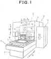
- Fig.1 is a laser beam machine 1 which is an embodiment of the present invention.
- the laser beam machine 1 to which the invention is applied is a CNC unit for machining (NC cutting machine) , for instance.
- the laser beam machine 1 has a workpiece stationing unit 1a, a laser beam radiating unit 1b and a control unit 1c.
- the laser beam radiating unit 1b is located on the workpiece stationing unit 1a, and the control unit 1c is provided, attaching to the workpiece stationing unit 1a and the laser beam radiating unit 1b.
- the workpiece stationing unit 1a has a base 2 for fixing the laser beam machine 1 on a floor, and a table 3 is located on an upper face of the base 2.
- the table 3 has a horizontal workpiece location surface 3a for putting the workpiece 70 thereon, and the workpiece location surface 3a freely moves and drives in a direction as shown by arrows A and B (X-axis direction) with respect to the base 2 by a proper driving motor (not shown).
- the workpiece location surface 3a is provided with earthing process means (not shown) for earthing the located workpiece 60.
- the laser beam radiating unit 1b has a column 5 and the column 5 is fixed on the base 2, bridging over the table 3 which can move in the X-axis direction so as not to interfere with the table 3.
- the column 5 has rails for saddle 5a, 5a along a horizontal direction as shown by arrows C and D perpendicular to the X-axis direction (a Y-axis direction), and the rails for saddle 5a, 5a are provided with a saddle 6 which freely moves and drives in the Y-axis direction with respect to the column 5 by a proper driving motor (not shown).
- a machining head body (not shown) is provided inside the saddle 6, and the machining head body freely moves and drives in a direction as shown by arrows E and F perpendicular to the X-axis and Y-axis directions (a Z-axis direction) with respect to the column 5 by a proper driving motor (not shown).
- the column 5 has a laser beam oscillator (not shown) at a position on the arrow B side of Fig. 1 rather than the saddle 6.
- Laser beam medium of the laser beam oscillator is a CO 2 (carbon dioxide) or YAG (yttrium /alminium /monocrystal garnet) .
- the laser beam oscillator freely oscillates and ejects through the medium.
- the later beam oscillator is connected with the machining head body through a laser beam path tube 7.
- the laser beam path tube 7 has a path tube 7a (only a part of which is shown in the figure with a broken line) connected with the laser beam oscillator, and an expandable tube 7b for connecting the path tube 7a and the machining head body with each other in the direction as shown by the arrows A and B.
- the expandable tube 7b has a telescopic mechanism for expanding together with a movement between the saddle 6 and the path tube 7a. That is, the laser beam oscillated and ejected by the laser beam oscillator can reach the machining head body inside the saddle 6, passing through an inside of the path tube 7a of the laser beam path tube 7, and then passing through an inside of the expandable tube 7b.
- the machining head body has an outside sleeve member 9, and the outside sleeve member 9 is supported by an axis so as to be rotated, driven and positioned with respect to the machining head body with an axial center CT1 parallel to the Z-axis as its center by a proper driving motor (not shown).
- the outside sleeve member 9 is provided with a rotating top end member 10, and the rotating top end member 10 is supported by an axis so as to be freely rotated, driven and positioned with respect to the outside sleeve member 9 with a horizontal axial center CT2 perpendicular to the axial center CT1 as its center by a proper driving motor (not shown).
- the rotating top end member 10 is provided with a torch 20 which can face the workpiece location surface 3a at right angles thereto. And, the torch 20 is provided with a servo motor (not shown) , and the torch 20 freely moves and is freely positioned in the vertical direction in the figure through the servo motor.
- a proper reflecting mirror (not shown) is provided inside the outside sleeve member 9 and the rotating top end member 10. This reflecting mirror is for passing the laser beam, which reached the machining head body and passed through the inside of the machining head body, through the insides of the outside sleeve member 9, the rotating top end member 10 and the torch 20, and for radiating the laser beam on the workpiece 60 from the normal line direction.
- a proper converging lens (not shown) is provided inside the outside sleeve member 9, and the converging lens can converge the laser beam on a predetermined position on the workpiece 60 to be converged.
- the torch 20 is provided with assist gas evolution means (not shown) connected with a bomb of assist gas, such as nitrogen.
- the assist gas evolution means freely evolve assist gas to the workpiece 60.
- Fig.2 shows the torch wherein (a) is a schematic side view (a sectional view in a part) and (b) is a schematic bottom view.
- the torch 20 is provided with an inside sleeve member 21 having a hollow portion 21a in the shape of almost a cone so as not to obstruct the converged laser beam RZ (shown with a two-dot chain line).
- the inside sleeve member 21 is engaged with the rotating top end member 10 as shown in Fig.1 through a holding portion 25.
- an opening portion 21b is provided, and a center electrode 23 is fitted in the opening portion 21b.
- the center electrode 23 is comprised of proper conductive material, and is almost cylindrically formed. This cylindrical center electrode 23 is open on the upper side in the figure so as not to obstruct the laser beam RZ (shown with a two-dot chain line) , similar to the inside sleeve member 21. As shown in Fig.2 (b) , a plasma opposed face 23b almost cylindrically formed is provided on the lower hand of the cylindrical center electrode in the figure, and an opening 23a for the laser beam RZ is provided at the center of the plasma opposed face 23b.
- a first guard electrode 27a is provided at the outer periphery of the center electrode 23 through an insulating layer 26a comprised of proper material.
- the first guard electrode 27a is comprised of proper conductive material, and is almost cylindrically formed, as shown in Fig.2(a).
- a sensor electrode 28 is provided at the outer periphery of the first guard electrode 27a through an insulating layer 26b. Similar to the first guard electrode 27a, the sensor electrode 28 is comprised of proper conductive material, and is almost cylindrically formed, as shown in Fig.2(a).
- a second guard electrode 27b is provided at the outer periphery of the sensor electrode 28 through an insulating layer 26c.
- the second guard electrode 27b is also comprised of proper conductive material, and is almost cylindrically formed, as shown in Fig.2 (a) .
- the first guard electrode 27a is electrically connected with the second guard electrode 27b through a contacting portion CT.
- the first guard electrode 27a, the sensor electrode 28 and the second guard electrode 27b are respectively annularly formed, as shown in Fig.2 (b) . That is, the torch 20 is comprised of the plasma opposed face 23b of the center electrode 23, the insulating layer 26a, the first guard electrode 27a, the insulating layer 26b, the sensor electrode 28, the insulating layer 26c and the second guard electrode 27b, concentrically in this order with the opening 23a of the center electrode 23 as its center.
- the first guard electrode 27a and the second guard electrode 27b are referred to as only "the guard electrodes 27a, 27b" if both are not necessary to be discriminated from each other.
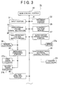
- Fig.3 is a block diagram showing the control unit 1c.
- the control unit 1c of the laser beam machine 1 has a main control portion 30, as shown in Fig.3.
- An input portion 31, such as a keyboard, a machining control portion 32, a displacement volume computing portion 33, a standard voltage memory 35, a high frequency voltage supply portion 36, a servo motor driving control portion 37, a center electrode potential control portion 39, a voltage detecting portion 40 are connected with the main control portion 30 via a bus line 41.
- a servo motor 37a is connected with the servo motor driving control portion 37.
- the sensor electrode 28 is connected with the high frequency voltage supply portion 36, and is connected with the first guard electrode 27a and the second guard electrode 27b through an impedance converting portion 38.
- the center electrode 23 is connected with the center electrode potential control portion 39.
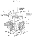
- Fig.4 is a schematic circuit diagram in the surroundings of the impedance converting portion 38 and the center electrode potential control portion 39. In order to easily understand the invention, only necessary elements are shown in Fig.4, so, the actual circuit is more complex and includes various kinds of active elements and passive elements.
- the high frequency voltage supply portion 36 is provided with a high frequency power supply (not shown) , and the high frequency voltage supply portion 36 can output high frequency voltage V HF the frequency of which is kH z through MH z order with the high frequency power supply.
- the impedance converting portion 38 (in a frame with a broken line) is provided with an operational amplifier OP, and the impedance converting portion 38 functions as a voltage follower if an output terminal of the operational amplifier OP is connected with a reverse input terminal (minus terminal) of the operational amplifier OP without locating a resistance therebetween. That is, the amplification factor of the impedance converting portion 38 is almost one (1) , and the impedance converting portion 38 has an input portion 38a, input impedance of which is infinity ( ⁇ ) , and an output portion 38b output impedance of which is zero (0) .
- the input impedance infinity ( ⁇ ) and the output impedance zero (0) means that the relation between the input impedance and the output impedance is an approximative relation of infinity ( ⁇ ) and zero (0) .
- the high frequency voltage supply portion 36 is connected with a proper resistance R, and is respectively connected with the sensor electrode 28 and the input portion 38a of the impedance converting portion 38 through a junction IN. And, the output portion 38b of the impedance converting portion 38 is respectively connected with the first guard electrode 27a and the voltage detecting portion 40 through a junction OUT.
- the output portion 38b is connected with the second guard electrode 27b through the first guard electrode 27b since the first guard electrode 27a is electrically connected with the second guard electrode 27b through the contacting portion CT, as mentioned before.
- the center electrode potential control portion 39 is provided with a constant voltage power supply VS, and the constant voltage power supply VS is earthed. That is, the center electrode potential control portion 39 is comprised so that it can output constant positive voltage to the center electrode 23, or it can earth the center electrode 23 in case of 0V (in case where it outputs no voltage).
- an operator In order to machine the workpiece 60 with the laser beam machine 1 having the above-mentioned structure, an operator firstly put the workpiece 60 to be machined on the workpiece location surface 3a, as shown in Fig.1. And, the operator boots the laser beam 1 through a booting switch (not shown) owned by the control unit 1c, so that earthing process means is actuated and the located workpiece 60 is earthed.
- a booting switch owned by the control unit 1c
- earthing process means is actuated and the located workpiece 60 is earthed.
- the operator inputs a machining instruction on the basis of a machining condition, such as material and board thickness, and a predetermined machining shape, through the input portion 31, such as a keyboard, the main control portion 30 instructs the machining control portion 32 to execute the control according to the machining instruction, receiving the instruction.
- the machining control portion 32 drives and controls driving motors (not shown) for respective axes, so that the torch 20 is moved and driven in predetermined axial directions in the X-, Y-, Z-axes , so as to locate the torch 20 at a predetermined position (such as a piercing point) .
- the laser beam oscillator (not shown) is driven so as to eject the laser beam RZ.
- the ejected laser beam RZ is radiated on the workpiece 60 through the laser beam path tube 7, the machining head body (not shown), the outside sleeve member 9, the rotating top end member 10, and the torch 20.
- the assist gas evolution means (not shown) is actuated together with radiation of the laser beam RZ , and assist gas is discharged to the workpiece 60.
- the machining control portion 32 When the laser beam RZ is thus radiated on the workpiece 60, the machining control portion 32 relatively moves the torch 20 with respect to the workpiece 60 along a machining form according to the machining instruction by properly rotating, driving and positioning the base 3, the saddle 6, the machining head body, the outside sleeve member 9, the rotating top end member 10. At this time, a surface following control for keeping a gap length GAP between the top end of the torch 20 and the workpiece 60 in an almost constant state is executed together with the movement of the torch 20.
- Fig. 5 is a view showing surface following control according to the invention, and is an explanation view at the time when the center electrode 23 is earthed.
- the sensor electrode 28 faces the workpiece 60
- the annular sensor electrode 28 as shown in Fig.2 (b) and the workpiece 60 facing this elelctrode 28 function as facing electrodes for a condenser, so that capacitance C GAP is generated between both.
- the resistance R and the capacitance C GAP comprise a series circuit with respect to the high frequency voltage supply portion 36 since the workpiece 60 is earthed by the earthing process means.
- capacitance Ca is generated between the first guard electrode 27a and the workpiece 60, similar to the capacitance C GAP , and capacitance Cb is generated between the second guard electrode 27b and the workpiece 60. So, the capacitance Ca and the capacitance Cb comprise a parallel circuit with respect to the output portion 38b of the impedance converting portion 38.
- the high frequency voltage supply portion 36 outputs the high frequency voltage V HF in the above-mentioned state
- the high frequency voltage V HF is inputted in the sensor electrode 28 through the resistance R. Since the resistance R and the capacitance C GAP comprises a series circuit as mentioned before, the potential V IN in the junction IN corresponds to the voltage drop of the capacitance C GAP , and is the voltage a predetermined voltage value lower and predetermined phase shifted in comparison with the high frequency voltage V HF ("the voltage V GAP " hereinafter) .
- the voltage V GAP is inputted in the input portion 38a of the impedance converting portion 38, and this voltage V GAP is outputted as potential V OUT in the junction OUT as it is since the amplification factor of the impedance converting portion 38 is almost one (1).
- the outputted voltage V GAP is respectively inputted in the first guard electrode 27a and the second guard electrode 27b since the capacitance Ca and the capacitance Cb comprises a series circuit as mentioned before.
- the voltage V GAP inputted in the first guard electrode 27a, the second guard electrode 27b and the sensor electrode 28 is the same phase, so that a line of electric force F GAP from the sensor electrode 28 flows into the facing workpiece 60 without flowing into the adjacent guard electrodes 27a, 27b (that is, without newly generating capacitance different from the capacitance C GAP ).
- the inputted voltage V GAP is the same voltage value, so that the line of electric force F GAP is respectively parallel to a line of electric force FLa from the first guard electrode 27a and a line of electric force FLb from the second guard electrode 27b which are adjacent to the line of electric force F GAP without flowing into the workpiece 60 broadening from the sensor electrode 28.
- the surface of the workpiece 60 in a normal direction with respect to the sensor electrode 28 as shown in Fig.2(b), that is, the portion of the workpiece 60 on which the annular electrode is projected functions as the facing electrode of the capacitance C GAP on the workpiece 60 side.
- the sectional area of the facing electrode in the capacitance C GAP (the area of the above-mentioned annular electrode) is almost constant, so that the capacitance C GAP changes only according to the gap length GAP as shown in Fig.5 (that is, the minimum distance between the sensor electrode 28 and the workpiece 60).
- the relation is that the capacitance C GAP becomes smaller (the voltage V GAP becomes bigger) when the gap length GAP becomes bigger, and the capacitance C GAP becomes bigger (the voltage V GAP becomes smaller) when the gap length GAP becomes smaller. That is, in order to execute the surface following control, predetermined voltage V GAP according to a predetermined gap length GAP ("the standard voltage value" hereinafter) is set in advance and the voltage V GAP is detected so as to amend the difference with respect to the standard voltage value during the control of the movement of the torch 20.
- the standard voltage value the standard voltage value
- the voltage detecting portion 40 always detects the potential V OUT during the control of the movement of the torch 20.
- the portion 40 detects this and outputs the detected result to the displacement volume computing portion 33.
- the sensor electrode 28 is an annularly formed electrode in this embodiment. But, it is not always necessary to be a continuous "annulus" as shown in Fig.2 (b) , but may be a discontinuous "annulus". For instance, a predetermined number of notches (one, two or three, for instance) may be formed on the sensor electrode 28 as shown in Fig.2(b) or the divided sensor electrodes may be annularly arranged.
- a table having standard voltage values corresponding to the gap length GAP to be set is prepared in the standard voltage memory 35.
- the displacement volume computing portion 33 accesses the table from the standard voltage memory 35 at the time of start of the surface following control, and sets the standard voltage value corresponding to the gap length GAP to be set on the basis of the machining condition (such as material and board thickness) inputted by the operator.
- the displacement volume computing portion 33 computes a voltage value V corresponding to a difference with respect to a standard voltage value on the basis of the detected result received from the voltage detecting portion 40.
- the displacement volume of the torch 20 with respect to the gap length GAP is computed from a relational expression between the voltage value V and the displacement volume of the torch 20 with respect to the gap length GAP (that is, a displacement angle of the servo motor 37a) on the basis of the computed voltage value V, and the computed displacement volume of the torch 20 is outputted to the servo motor driving control portion 37. Thereafter, the servo motor driving control portion 37 controls to drive the servo motor 37a a predetermined displacement angle according to the displacement volume of the torch 20. Then, the torch 20 is moved in the upper or the lower direction of Fig.5 and is positioned, so that the gap length GAP is almost constantly kept.
- the displacement volume of the torch 20 is immediately computed by the displacement volume computing portion 33 according to undulations on the surface of the workpiece 60 and the torch 20 is thus moved and positioned so as to almost constantly keep the gap length GAP by the servo motor 37a . Therefore, the focal point of the laser beam RZ is kept at a predetermined position to be focused (such as a machining point P as shown in Fig. 5) on the workpiece 60.
- the guard electrodes 27a, 27b are not always necessary to be provided, but the sensor electrode 28 may be formed with an insulating member without providing the guard electrodes 27a, 27b at the inside and outside peripheries thereof although the accuracy of the surface following control is reduced.
- plasma PZ comprised of charged particles, such as an ion and an electron e, is generated between the torch 20 and the workpiece 60.
- the line of electric force FLa intervenes between the plasma PZ and the capacitance C GAP . Therefore, a line of electric force FL GAP from the sensor electrode 28 does not flow into the plasma PZ (that is, the capacitance C GAP does not change) , but the line of electric force FLa flows into the plasma PZ. Then, the capacitance Ca changes.
- the voltage detecting portion 40 can detect the voltage V GAP according to the gap length GAP without receiving the influence of the variation of the capacitance Ca on the voltage V GAP since the impedance converting portion 38 functioning as a voltage follower intervenes between the capacitance Ca and the capacitance C GAP - By doing so, it is possible to control so as to almost constantly keep the gap length GAP even if the plasma PZ is generated.
- the impedance converting portion 38 is the voltage follower, but the amplification factor is not always one (1) so long as the input impedance is infinity ( ⁇ ) and the output impedance is zero (0).
- the capacitance C GAP can be excluded from the plasma PZ, restricting the charged particles in a space between the torch 20 and the workpiece 60.
- the line of electric force FLb is generated from the second guard electrode 27b around the outer periphery of the capacitance C GAP .
- the torch 20 approaches an oblique portion 60a (two-dot chain line) of the workpiece 60 as shown in Fig.5
- the line of electric force FL GAP from the sensor electrode 28 does not flow into the oblique portion 60a (that is, the capacitance C GAP is not changed) , but the line of electric force FLb flows into the oblique portion 60a.
- the capacitance Cb changes, but the voltage detecting portion 40 can detect the voltage V GAP according to the gap length GAP even if there is an undulation, such as the oblique portion 60a on the workpiece 60 without receiving an influence owing to the variation of the capacitance Cb by the impedance converting portion 38, similar to the above-mentioned.
- the capacitance C GAP is excluded from the plasma PZ, and the above-mentioned surface following control is thus executed, functioning normally.
- the line of electric force FLa by the high frequency voltage can not restrict the plasma PZ in the space between the torch 20 and the workpiece 60, and the plasma PZ is dispersed in the space.
- the plasma PZ approaches the line of electric force FLa, and attracts much of the line of electric force FLa therein.
- the line of electric force FL GAP from the sensor electrode 28 flows to the plasma PZ, so that the capacitance C GAP changes, and the surface following control does not normally function, thereby.
- the laser beam machine 1 is for realizing normal surface following control function in such a manner that the charged particles of the plasma PZ are absorbed so that the plasma PZ does not approach the line of electric force FLa for restriction of the dispersion of the plasma PZ even if a large volume of the plasma PZ is generated.
- the center electrode 23 is connected with the center electrode potential control portion 39, as shown in Fig.5, and the center electrode potential control portion 39 is actuated together with the start of the above-mentioned surface following control.
- the center electrode potential control portion 39 controls to earth the center electrode 23 without outputting voltage.
- the whole plasma opposed face 23b of the center electrode 23 enters in a state that the potential is zero (0), so that the center electrode potential control portion 39 absorb (earth) the charged particles , such as an electron e, on the plasma opposed face 23b through the face 23b.
- the charged particles are absorbed when the plasma PZ is in a contact with the plasma opposed face 23b or when the plasma PZ electrifies the plasma opposed face 23b, for instance.
- the dispersion of the plasma PZ in the space between the torch 20 and the workpiece 60 can be thus restricted since the charged particles, such as the electron e, are absorbed in order through the plasma opposed face 23b during the execution of the above-mentioned surface following control. Then, the line of electric force FLa is prevented frombeing attracted in the plasma PZ even if a large volume of plasma PZ is generated, and the surface following control can normally function.
- the plasma opposed face 23b of the center electrode 23 is concentrically formed with the opening 23a for the laser beam RZ as its center, as shown in Fig.2 (b) . Therefore, the dispersion of the plasma PZ can be effectively restricted by absorbing the charged particles of the plasma PZ concentrically dispersed from the machining point P.
- the method of absorbing the charged particles by the center electrode potential control portion 39 is to earth the center electrode 23 in the embodiment. But, the potential of the center electrode 23 may be controlled to keep positive voltage in order to do so.
- Fig.6 is a view showing the surface following control according to the invention and is an explanation view in case where the center electrode 23 is controlled to keep a positive potential.
- the charged particles in the plasma PZ are electrons e and, plus ions and minus ions.
- the electron e is easy to be dispersed in comparison with the ion since its mass is smaller, so that it is broadly dispersed in the space between the torch 20 and the workpiece 60. In the end, it is effective to absorb the electrons e of the charged particles for restriction of the dispersion of the plasma PZ.
- the center electrode potential control portion 39 outputs 5v of voltage, for instance, as shown in Fig.6. Then, the whole plasma opposed face 23b of the center electrode 23 enters in such a state that the voltage is 5v, that is, the positive. Therefore, the center electrode potential control portion 39 generates Coulomb's force facing the plasma opposed face 23b on the electrons e (and minus ions) of the plasma PZ dispersed in the space between the torch 20 and the workpiece 60 in addition to the electrons e (and minus ions) on the plasma opposed face 23b so as to absorb (earth) through the plasma opposed face 23b.
- the charged particles dispersed in the space between the torch 20 and the workpiece 60 can be absorbed, and the dispersion of the plasma PZ can be further restricted, thereby.
- the center electrode potential control portion 39 thus controls the potential of the center electrode 23 so as to keep the positive constant voltage during the execution of the surface following control, the dispersion of the plasma PZ is restricted, and the surface following control normally functions, so that the focus of the laser beam RZ can be always kept at the predetermined position on the workpiece 60 to be focused.
Landscapes
- Physics & Mathematics (AREA)
- Optics & Photonics (AREA)
- Engineering & Computer Science (AREA)
- Plasma & Fusion (AREA)
- Mechanical Engineering (AREA)
- Laser Beam Processing (AREA)
Abstract
Laser beam radiating means has a center electrode
at an inner periphery of an annular electrode.
Center electrode potential control means controls
potential of the center electrode so as to keep zero
(0) or positive constant voltage, so that it is
possible to absorb charged particles in plasma
generating by radiation of laser beam through the
center electrode, and dispersion of plasma can be
restricted thereby. Even if a large volume of plasma
is generated, a line of electric force from the
annular electrode is not disturbed by plasma, and
the variation of capacitance generating between the
annular electrode and a workpiece can be prevented,
thereby.
Description
- The present invention relates to a laser beam machine for executing cutting machining on a workpiece. More specifically, the present invention relates to a laser beam machine for controlling a gap length between a top end of a torch and a workpiece on the basis of capacitance between an annular electrode which is provided at the torch and the workpiece.
- Such kind of a conventional laser beam machine has an annular electrode provided at a torch for radiating laser beam, and has a surface following control function for controlling so as to keep the focus position of laser beam at a predetermined position on a workpiece to be focused, relatively moving and driving the torch with respect to the workpiece by constantly controlling a gap length between the top end of the torch and the workpiece on the basis of capacitance generating between the annular electrode and the workpiece.
- But, the capacitance varies irrespective of the gap length since plasma comprised of charged particles, such as ions and electrons, is generated from a machining point when radiating laser beam on the workpiece, so that sometimes, the above-mentioned surface following control does not normally function. On the contrary, another laser beam machine having an annular electrode located away from a machining point, such as a first patent application reference (Publication No. S64-22490, Pages 6-8, Fig. 1) , has been proposed. In this laser beam machine, but plasma approaches the annular electrode if a large volume of plasma is generated, and the capacitance varies thereby, inconveniently similar to the above-mentioned laser beam machine.
- Under this situation, another laser beam has been proposed, such as a second patent application reference (Publication No.H03-165989, Pages 7-9, Fig.1). In this laser beam machine, a
guard electrode 52 is located at an inner periphery of anannular electrode 51 provided at thetorch 50 through aninsulating layer 53, as shown in Fig.7(a), and theguard electrode 52 is supplied with high frequency voltage so as to generate a line of electric force. FL by the high frequency voltage, so that capacitance CGAP can be electrically excluded from plasma PZ in order to prevent the variation of the capacitance CGAP by the plasma PZ . - In such a laser beam machine also, but, the surface following control does not normally function, similar to the above-mentioned cases since the line of electric force FL by high frequency voltage is attracted in the plasma PZ if a large volume of plasma PZ is generated as shown in Fig.7(b), so that the capacitance CGAP can not be fully excluded from the plasma PZ, and capacitance CPZ for varying the capacitance CGAP is generated between the
annular electrode 51 and the plasma PZ. - Under the circumstances, development of a laser beam machine through which the surface following control can normally function even if a large volume of plasma is generated due to radiation of laser beam, has been desired.
- The present invention is a laser beam machine having laser beam radiating means for radiating laser beam on a workpiece, the laser beam radiating means having an opening for the laser beam and an annular electrode facing the workpiece provided at an outer periphery of the opening, the laser beam machine further having gap length control means for controlling gap length between the laser beam radiating means and the workpiece on the basis of capacitance generating between the annular electrode and the workpiece, comprising:
- the laser beam radiating means having a center electrode at an inner periphery of the annular electrode; and
- center electrode potential control means for controlling potential of the center electrode so as to keep zero (0) or a positive constant voltage.
-
- According to this aspect of the invention, the laser beam radiating means has the center electrode at the inner periphery of the annular electrode, and the center electrode potential control means controls the potential of the center electrode so as to keep zero (0) or a positive constant voltage, so that the charged particles (such as electrons and ions) in the plasma generated owing to radiation of laser beam which is on the center electrode which was controlled so as to keep the constant voltage can be absorbed through the center electrode, and the dispersion of plasma in the space between the laser beam radiating means and the workpiece can be restricted, thereby. By doing so, the line of electric force from the annular electrode (such as FLGAP as shown Figs. 5 and 6) is not disturbed by the plasma even if a large volume of plasma is generated, and the variation of the capacitance generating between the annular electrode and the workpiece can be prevented. And, the gap length control means can control the gap length between the laser beam radiating means and the workpiece with no error operation.
- If the potential of the center electrode is controlled so as to keep the positive constant voltage, the charged particles, such as electrons and minus ions, dispersed in the space between the laser beam radiating means and the workpiece can be absorbed through the center electrode which was controlled so as to keep the positive constant voltage in addition to the charged particles on the center electrode, so that the dispersion of the plasma in the space between the laser beam radiating means and the workpiece can be further restricted.
- Another aspect of the invention is the laser beam machine, wherein the center electrode has a workpiece facing surface concentrically formed with the opening for the laser beam as its center.
- According to this aspect of the invention, the center electrode has the workpiece facing face which is concentrically formed with the opening for laser beam as its center, so that the charged particles of the plasma almost concentrically dispersed from the machining point facing the opening (such as P as shown in Figs.5 and 6) are absorbed through the workpiece facing face, and the dispersion of the plasma can be effectively restricted.
- Besides, the another aspect of the invention is the laser beam machine, wherein the laser beam radiating means has a first guard annular electrode which intervenes between the center electrode and the annular electrode, an impedance converting means is provided, having an input portion input impedance of which is infinity (∞) for connecting with the annular electrode and an output portion output impedance of which is zero (0) for connecting with the first guard annular electrode, and high frequency voltage supply means for supplying the annular electrode with high frequency voltage is provided.
- According to this aspect of the invention, the laser beam radiating means has the first guard annular electrode which intervenes between the center electrode and the annular electrode, and the impedance converting means has the input portion input impedance of which is infinity ( ∞ ) for connecting with the annular electrode and the output portion output impedance of which is zero (0) for connecting with the first guard annular electrode. The high frequency voltage supply means supplies the annular electrode with high frequency voltage, and the predetermined voltage (such as VGAP) by the supplied high frequency voltage is applied on the annular electrode and the first guard annular electrode through the input portion and the output portion of the impedance converting means, so that it is possible to prevent the predetermined voltage (such as VGAP) from varying even if the capacitance (such as Ca as shown in Figs.5 and 6) generating between the first guard annular electrode and the workpiece varies. By doing so, the line of electric force (such as FLa as shown in Figs.5 and 6) from the first guard annular electrode can intervene between plasma and the capacitance generating between the annular electrode and the workpiece. Then, the line of electric force (such as FLGAP as shown in Figs. 5 and 6) from the annular electrode does not flow into the plasma, and the variation of the capacitance generating between the annular electrode and the workpiece can be further prevented.
- The line of electric force (such as FLa as shown in Figs.5 and 6) from the first guard annular electrode is generated by high frequency voltage, so that the charged particles in the plasma can be restricted in the space between the laser beam radiating means and the workpiece without giving the charged particles constant Coulomb's force, and the dispersion of the plasma can be restricted thereby.
- Another aspect of the invention is the laser beam machine, wherein the laser beam radiating means has a second guard annular electrode which is connected with the output portion of the impedance converting means at an outer periphery of the annular electrode.
- According to this aspect of the invention, the laser beam radiating means has the second guard annular electrode which is connected with the output portion of the impedance converting means at the outer periphery of the annular electrode, and the predetermined voltage (such as VGAP) by the high frequency voltage supplied from the high frequency voltage supply means is applied on the second guard annular electrode in addition to on the annular electrode and the first guard annular electrode, so that the line of electric force from the annular electrode (such as FLGAP as shown in Figs.5 and 6) can flow 'into the workpiece from a normal direction. Therefore, the capacitance generating between the annular electrode and the workpiece can be changed according to only gap length, and the gap length control means can control the gap length with high accuracy.
-
- Fig. 1 is a perspective view showing the whole laser beam machine to which the invention is applied;
- Fig.2 is a view showing a torch, wherein (a) is a schematic side view (a sectional view in a part) and (b) is a schematic bottom view;
- Fig.3 is a block diagram showing a control unit;
- Fig.4 is a schematic circuit view in surroundings of an impedance converting portion and a center electrode potential control portion;
- Fig.5 is a view showing surface following control
according to the invention, and is an explanation
view at the time when a
center electrode 23 is earthed; - Fig.6 is a view showing the surface following control according to the invention, and is an explanation view in case where the center electrode is controlled to keep a positive potential; and
- Fig. 7 is an explanation view of the surface following control according to a conventional laser beam machine, wherein (a) is a view at the time when a small volume of plasma is generated and (b) is a view at the time when a large volume of plasma is generated.
-
- Fig.1 is a laser beam machine 1 which is an embodiment of the present invention. The laser beam machine 1 to which the invention is applied is a CNC unit for machining (NC cutting machine) , for instance. The laser beam machine 1 has a workpiece stationing unit 1a, a laser
beam radiating unit 1b and acontrol unit 1c. The laserbeam radiating unit 1b is located on the workpiece stationing unit 1a, and thecontrol unit 1c is provided, attaching to the workpiece stationing unit 1a and the laserbeam radiating unit 1b. - The workpiece stationing unit 1a has a
base 2 for fixing the laser beam machine 1 on a floor, and a table 3 is located on an upper face of thebase 2. The table 3 has a horizontalworkpiece location surface 3a for putting the workpiece 70 thereon, and theworkpiece location surface 3a freely moves and drives in a direction as shown by arrows A and B (X-axis direction) with respect to thebase 2 by a proper driving motor (not shown). And, theworkpiece location surface 3a is provided with earthing process means (not shown) for earthing the locatedworkpiece 60. - The laser
beam radiating unit 1b has a column 5 and the column 5 is fixed on thebase 2, bridging over the table 3 which can move in the X-axis direction so as not to interfere with the table 3. And, the column 5 has rails forsaddle saddle saddle 6 which freely moves and drives in the Y-axis direction with respect to the column 5 by a proper driving motor (not shown). - Inside the
saddle 6, a machining head body (not shown) is provided, and the machining head body freely moves and drives in a direction as shown by arrows E and F perpendicular to the X-axis and Y-axis directions (a Z-axis direction) with respect to the column 5 by a proper driving motor (not shown). - The column 5 has a laser beam oscillator (not shown) at a position on the arrow B side of Fig. 1 rather than the
saddle 6. Laser beam medium of the laser beam oscillator is a CO2 (carbon dioxide) or YAG (yttrium /alminium /monocrystal garnet) . The laser beam oscillator freely oscillates and ejects through the medium. Besides, the later beam oscillator is connected with the machining head body through a laser beam path tube 7. - The laser beam path tube 7 has a path tube 7a (only a part of which is shown in the figure with a broken line) connected with the laser beam oscillator, and an expandable tube 7b for connecting the path tube 7a and the machining head body with each other in the direction as shown by the arrows A and B. The expandable tube 7b has a telescopic mechanism for expanding together with a movement between the
saddle 6 and the path tube 7a. That is, the laser beam oscillated and ejected by the laser beam oscillator can reach the machining head body inside thesaddle 6, passing through an inside of the path tube 7a of the laser beam path tube 7, and then passing through an inside of the expandable tube 7b. - The machining head body has an
outside sleeve member 9, and theoutside sleeve member 9 is supported by an axis so as to be rotated, driven and positioned with respect to the machining head body with an axial center CT1 parallel to the Z-axis as its center by a proper driving motor (not shown). Theoutside sleeve member 9 is provided with a rotatingtop end member 10, and the rotatingtop end member 10 is supported by an axis so as to be freely rotated, driven and positioned with respect to theoutside sleeve member 9 with a horizontal axial center CT2 perpendicular to the axial center CT1 as its center by a proper driving motor (not shown). The rotatingtop end member 10 is provided with atorch 20 which can face theworkpiece location surface 3a at right angles thereto. And, thetorch 20 is provided with a servo motor (not shown) , and thetorch 20 freely moves and is freely positioned in the vertical direction in the figure through the servo motor. - A proper reflecting mirror (not shown) is provided inside the
outside sleeve member 9 and the rotatingtop end member 10. This reflecting mirror is for passing the laser beam, which reached the machining head body and passed through the inside of the machining head body, through the insides of theoutside sleeve member 9, the rotatingtop end member 10 and thetorch 20, and for radiating the laser beam on theworkpiece 60 from the normal line direction. - A proper converging lens (not shown) is provided inside the
outside sleeve member 9, and the converging lens can converge the laser beam on a predetermined position on theworkpiece 60 to be converged. Thetorch 20 is provided with assist gas evolution means (not shown) connected with a bomb of assist gas, such as nitrogen. The assist gas evolution means freely evolve assist gas to theworkpiece 60. - Fig.2 shows the torch wherein (a) is a schematic side view (a sectional view in a part) and (b) is a schematic bottom view. As shown in Fig.2 (a) , the
torch 20 is provided with aninside sleeve member 21 having ahollow portion 21a in the shape of almost a cone so as not to obstruct the converged laser beam RZ (shown with a two-dot chain line). Theinside sleeve member 21 is engaged with the rotatingtop end member 10 as shown in Fig.1 through a holdingportion 25. On the lower hand of theinside sleeve member 21 in the figure, an opening portion 21b is provided, and acenter electrode 23 is fitted in the opening portion 21b. - The
center electrode 23 is comprised of proper conductive material, and is almost cylindrically formed. Thiscylindrical center electrode 23 is open on the upper side in the figure so as not to obstruct the laser beam RZ (shown with a two-dot chain line) , similar to theinside sleeve member 21. As shown in Fig.2 (b) , a plasma opposedface 23b almost cylindrically formed is provided on the lower hand of the cylindrical center electrode in the figure, and anopening 23a for the laser beam RZ is provided at the center of the plasma opposedface 23b. - A
first guard electrode 27a is provided at the outer periphery of thecenter electrode 23 through an insulatinglayer 26a comprised of proper material. Thefirst guard electrode 27a is comprised of proper conductive material, and is almost cylindrically formed, as shown in Fig.2(a). Asensor electrode 28 is provided at the outer periphery of thefirst guard electrode 27a through an insulatinglayer 26b. Similar to thefirst guard electrode 27a, thesensor electrode 28 is comprised of proper conductive material, and is almost cylindrically formed, as shown in Fig.2(a). And, asecond guard electrode 27b is provided at the outer periphery of thesensor electrode 28 through an insulatinglayer 26c. Similar to thefirst guard electrode 27a and thesensor electrode 28, thesecond guard electrode 27b is also comprised of proper conductive material, and is almost cylindrically formed, as shown in Fig.2 (a) . Thefirst guard electrode 27a is electrically connected with thesecond guard electrode 27b through a contacting portion CT. - That is, the
first guard electrode 27a, thesensor electrode 28 and thesecond guard electrode 27b are respectively annularly formed, as shown in Fig.2 (b) . That is, thetorch 20 is comprised of the plasma opposedface 23b of thecenter electrode 23, the insulatinglayer 26a, thefirst guard electrode 27a, the insulatinglayer 26b, thesensor electrode 28, the insulatinglayer 26c and thesecond guard electrode 27b, concentrically in this order with theopening 23a of thecenter electrode 23 as its center. In the following explanation, thefirst guard electrode 27a and thesecond guard electrode 27b are referred to as only "theguard electrodes - Fig.3 is a block diagram showing the
control unit 1c. Thecontrol unit 1c of the laser beam machine 1 has amain control portion 30, as shown in Fig.3. Aninput portion 31, such as a keyboard, amachining control portion 32, a displacementvolume computing portion 33, astandard voltage memory 35, a high frequencyvoltage supply portion 36, a servo motor drivingcontrol portion 37, a center electrodepotential control portion 39, avoltage detecting portion 40 are connected with themain control portion 30 via abus line 41. - A
servo motor 37a is connected with the servo motor drivingcontrol portion 37. Thesensor electrode 28 is connected with the high frequencyvoltage supply portion 36, and is connected with thefirst guard electrode 27a and thesecond guard electrode 27b through animpedance converting portion 38. Thecenter electrode 23 is connected with the center electrodepotential control portion 39. - Fig.4 is a schematic circuit diagram in the surroundings of the
impedance converting portion 38 and the center electrodepotential control portion 39. In order to easily understand the invention, only necessary elements are shown in Fig.4, so, the actual circuit is more complex and includes various kinds of active elements and passive elements. - The high frequency
voltage supply portion 36 is provided with a high frequency power supply (not shown) , and the high frequencyvoltage supply portion 36 can output high frequency voltage VHF the frequency of which is kHz through MHz order with the high frequency power supply. - The impedance converting portion 38 (in a frame with a broken line) is provided with an operational amplifier OP, and the
impedance converting portion 38 functions as a voltage follower if an output terminal of the operational amplifier OP is connected with a reverse input terminal (minus terminal) of the operational amplifier OP without locating a resistance therebetween. That is, the amplification factor of theimpedance converting portion 38 is almost one (1) , and theimpedance converting portion 38 has aninput portion 38a, input impedance of which is infinity (∞) , and anoutput portion 38b output impedance of which is zero (0) . The input impedance infinity (∞) and the output impedance zero (0) means that the relation between the input impedance and the output impedance is an approximative relation of infinity (∞) and zero (0) . - The high frequency
voltage supply portion 36 is connected with a proper resistance R, and is respectively connected with thesensor electrode 28 and theinput portion 38a of theimpedance converting portion 38 through a junction IN. And, theoutput portion 38b of theimpedance converting portion 38 is respectively connected with thefirst guard electrode 27a and thevoltage detecting portion 40 through a junction OUT. Theoutput portion 38b is connected with thesecond guard electrode 27b through thefirst guard electrode 27b since thefirst guard electrode 27a is electrically connected with thesecond guard electrode 27b through the contacting portion CT, as mentioned before. - The center electrode
potential control portion 39 is provided with a constant voltage power supply VS, and the constant voltage power supply VS is earthed. That is, the center electrodepotential control portion 39 is comprised so that it can output constant positive voltage to thecenter electrode 23, or it can earth thecenter electrode 23 in case of 0V (in case where it outputs no voltage). - In order to machine the
workpiece 60 with the laser beam machine 1 having the above-mentioned structure, an operator firstly put theworkpiece 60 to be machined on theworkpiece location surface 3a, as shown in Fig.1. And, the operator boots the laser beam 1 through a booting switch (not shown) owned by thecontrol unit 1c, so that earthing process means is actuated and the locatedworkpiece 60 is earthed. When the operator inputs a machining instruction on the basis of a machining condition, such as material and board thickness, and a predetermined machining shape, through theinput portion 31, such as a keyboard, themain control portion 30 instructs themachining control portion 32 to execute the control according to the machining instruction, receiving the instruction. - The
machining control portion 32 drives and controls driving motors (not shown) for respective axes, so that thetorch 20 is moved and driven in predetermined axial directions in the X-, Y-, Z-axes , so as to locate thetorch 20 at a predetermined position (such as a piercing point) . Then, the laser beam oscillator (not shown) is driven so as to eject the laser beam RZ. The ejected laser beam RZ is radiated on theworkpiece 60 through the laser beam path tube 7, the machining head body (not shown), theoutside sleeve member 9, the rotatingtop end member 10, and thetorch 20. Besides, the assist gas evolution means (not shown) is actuated together with radiation of the laser beam RZ , and assist gas is discharged to theworkpiece 60. - When the laser beam RZ is thus radiated on the
workpiece 60, themachining control portion 32 relatively moves thetorch 20 with respect to theworkpiece 60 along a machining form according to the machining instruction by properly rotating, driving and positioning thebase 3, thesaddle 6, the machining head body, theoutside sleeve member 9, the rotatingtop end member 10. At this time, a surface following control for keeping a gap length GAP between the top end of thetorch 20 and theworkpiece 60 in an almost constant state is executed together with the movement of thetorch 20. - Fig. 5 is a view showing surface following control according to the invention, and is an explanation view at the time when the
center electrode 23 is earthed. As shown in Fig.5, thesensor electrode 28 faces theworkpiece 60, and theannular sensor electrode 28 as shown in Fig.2 (b) and theworkpiece 60 facing thiselelctrode 28 function as facing electrodes for a condenser, so that capacitance CGAP is generated between both. So, the resistance R and the capacitance CGAP comprise a series circuit with respect to the high frequencyvoltage supply portion 36 since theworkpiece 60 is earthed by the earthing process means. - On the other hand, capacitance Ca is generated between the
first guard electrode 27a and theworkpiece 60, similar to the capacitance CGAP, and capacitance Cb is generated between thesecond guard electrode 27b and theworkpiece 60. So, the capacitance Ca and the capacitance Cb comprise a parallel circuit with respect to theoutput portion 38b of theimpedance converting portion 38. - If the high frequency
voltage supply portion 36 outputs the high frequency voltage VHF in the above-mentioned state, the high frequency voltage VHF is inputted in thesensor electrode 28 through the resistance R. Since the resistance R and the capacitance CGAP comprises a series circuit as mentioned before, the potential VIN in the junction IN corresponds to the voltage drop of the capacitance CGAP, and is the voltage a predetermined voltage value lower and predetermined phase shifted in comparison with the high frequency voltage VHF ("the voltage VGAP" hereinafter) . - The voltage VGAP is inputted in the
input portion 38a of theimpedance converting portion 38, and this voltage VGAP is outputted as potential VOUT in the junction OUT as it is since the amplification factor of theimpedance converting portion 38 is almost one (1). The outputted voltage VGAP is respectively inputted in thefirst guard electrode 27a and thesecond guard electrode 27b since the capacitance Ca and the capacitance Cb comprises a series circuit as mentioned before. - That is, the voltage VGAP inputted in the
first guard electrode 27a, thesecond guard electrode 27b and thesensor electrode 28 is the same phase, so that a line of electric force FGAP from thesensor electrode 28 flows into the facingworkpiece 60 without flowing into theadjacent guard electrodes first guard electrode 27a and a line of electric force FLb from thesecond guard electrode 27b which are adjacent to the line of electric force FGAP without flowing into theworkpiece 60 broadening from thesensor electrode 28. - Then, the surface of the
workpiece 60 in a normal direction with respect to thesensor electrode 28 as shown in Fig.2(b), that is, the portion of theworkpiece 60 on which the annular electrode is projected functions as the facing electrode of the capacitance CGAP on theworkpiece 60 side. Then, the sectional area of the facing electrode in the capacitance CGAP (the area of the above-mentioned annular electrode) is almost constant, so that the capacitance CGAP changes only according to the gap length GAP as shown in Fig.5 (that is, the minimum distance between thesensor electrode 28 and the workpiece 60). - The relation is that the capacitance CGAP becomes smaller (the voltage VGAP becomes bigger) when the gap length GAP becomes bigger, and the capacitance CGAP becomes bigger (the voltage VGAP becomes smaller) when the gap length GAP becomes smaller. That is, in order to execute the surface following control, predetermined voltage VGAP according to a predetermined gap length GAP ("the standard voltage value" hereinafter) is set in advance and the voltage VGAP is detected so as to amend the difference with respect to the standard voltage value during the control of the movement of the
torch 20. - The
voltage detecting portion 40 always detects the potential VOUT during the control of the movement of thetorch 20. When the VGAP outputted from theoutput portion 38b of theimpedance converting portion 38 is inputted in thevoltage detecting portion 40, theportion 40 detects this and outputs the detected result to the displacementvolume computing portion 33. - The
sensor electrode 28 is an annularly formed electrode in this embodiment. But, it is not always necessary to be a continuous "annulus" as shown in Fig.2 (b) , but may be a discontinuous "annulus". For instance, a predetermined number of notches (one, two or three, for instance) may be formed on thesensor electrode 28 as shown in Fig.2(b) or the divided sensor electrodes may be annularly arranged. - A table having standard voltage values corresponding to the gap length GAP to be set is prepared in the
standard voltage memory 35. The displacementvolume computing portion 33 accesses the table from thestandard voltage memory 35 at the time of start of the surface following control, and sets the standard voltage value corresponding to the gap length GAP to be set on the basis of the machining condition (such as material and board thickness) inputted by the operator. - The displacement
volume computing portion 33 computes a voltage value V corresponding to a difference with respect to a standard voltage value on the basis of the detected result received from thevoltage detecting portion 40. The displacement volume of thetorch 20 with respect to the gap length GAP is computed from a relational expression between the voltage value V and the displacement volume of thetorch 20 with respect to the gap length GAP (that is, a displacement angle of theservo motor 37a) on the basis of the computed voltage value V, and the computed displacement volume of thetorch 20 is outputted to the servo motor drivingcontrol portion 37. Thereafter, the servo motor drivingcontrol portion 37 controls to drive theservo motor 37a a predetermined displacement angle according to the displacement volume of thetorch 20. Then, thetorch 20 is moved in the upper or the lower direction of Fig.5 and is positioned, so that the gap length GAP is almost constantly kept. - When thus executing the surface following control, the displacement volume of the
torch 20 is immediately computed by the displacementvolume computing portion 33 according to undulations on the surface of theworkpiece 60 and thetorch 20 is thus moved and positioned so as to almost constantly keep the gap length GAP by theservo motor 37a . Therefore, the focal point of the laser beam RZ is kept at a predetermined position to be focused (such as a machining point P as shown in Fig. 5) on theworkpiece 60. - For execution of the above-mentioned surface following control, the
guard electrodes sensor electrode 28 may be formed with an insulating member without providing theguard electrodes - During the radiation of the laser beam RZ on the
workpiece 60, theworkpiece 60 fuses in the machining point P as shown in Fig.5. For this reason, plasma PZ comprised of charged particles, such as an ion and an electron e, is generated between thetorch 20 and theworkpiece 60. - As mentioned above, the line of electric force FLa intervenes between the plasma PZ and the capacitance CGAP. Therefore, a line of electric force FLGAP from the
sensor electrode 28 does not flow into the plasma PZ (that is, the capacitance CGAP does not change) , but the line of electric force FLa flows into the plasma PZ. Then, the capacitance Ca changes. But, thevoltage detecting portion 40 can detect the voltage VGAP according to the gap length GAP without receiving the influence of the variation of the capacitance Ca on the voltage VGAP since theimpedance converting portion 38 functioning as a voltage follower intervenes between the capacitance Ca and the capacitance CGAP- By doing so, it is possible to control so as to almost constantly keep the gap length GAP even if the plasma PZ is generated. In this embodiment, theimpedance converting portion 38 is the voltage follower, but the amplification factor is not always one (1) so long as the input impedance is infinity (∞) and the output impedance is zero (0). - Besides, it is possible to prevent the charged particles in the plasma PZ, such as an ion and an electron e, from approaching the
first guard electrode 27a without giving the charged particles Coulomb's force in a constant direction since the line of electric force FLa is generated by the high frequency voltage by the voltage VGAP. For this reason, the capacitance CGAP can be excluded from the plasma PZ, restricting the charged particles in a space between thetorch 20 and theworkpiece 60. - As mentioned before, the line of electric force FLb is generated from the
second guard electrode 27b around the outer periphery of the capacitance CGAP. When thetorch 20 approaches anoblique portion 60a (two-dot chain line) of theworkpiece 60 as shown in Fig.5, the line of electric force FLGAP from thesensor electrode 28 does not flow into theoblique portion 60a (that is, the capacitance CGAP is not changed) , but the line of electric force FLb flows into theoblique portion 60a. Therefore, the capacitance Cb changes, but thevoltage detecting portion 40 can detect the voltage VGAP according to the gap length GAP even if there is an undulation, such as theoblique portion 60a on theworkpiece 60 without receiving an influence owing to the variation of the capacitance Cb by theimpedance converting portion 38, similar to the above-mentioned. - The capacitance CGAP is excluded from the plasma PZ, and the above-mentioned surface following control is thus executed, functioning normally. Suppose that a large volume of the plasma PZ is generated between the
torch 20 and theworkiece 60, the line of electric force FLa by the high frequency voltage can not restrict the plasma PZ in the space between thetorch 20 and theworkpiece 60, and the plasma PZ is dispersed in the space. Thereafter, the plasma PZ approaches the line of electric force FLa, and attracts much of the line of electric force FLa therein. Then, the line of electric force FLGAP from thesensor electrode 28 flows to the plasma PZ, so that the capacitance CGAP changes, and the surface following control does not normally function, thereby. - Under this situation, the laser beam machine 1 according to the invention is for realizing normal surface following control function in such a manner that the charged particles of the plasma PZ are absorbed so that the plasma PZ does not approach the line of electric force FLa for restriction of the dispersion of the plasma PZ even if a large volume of the plasma PZ is generated.
- That is, the
center electrode 23 is connected with the center electrodepotential control portion 39, as shown in Fig.5, and the center electrodepotential control portion 39 is actuated together with the start of the above-mentioned surface following control. The center electrodepotential control portion 39 controls to earth thecenter electrode 23 without outputting voltage. Then, the whole plasma opposedface 23b of thecenter electrode 23 enters in a state that the potential is zero (0), so that the center electrodepotential control portion 39 absorb (earth) the charged particles , such as an electron e, on the plasma opposedface 23b through theface 23b. The charged particles are absorbed when the plasma PZ is in a contact with the plasma opposedface 23b or when the plasma PZ electrifies the plasma opposedface 23b, for instance. - The dispersion of the plasma PZ in the space between the
torch 20 and theworkpiece 60 can be thus restricted since the charged particles, such as the electron e, are absorbed in order through the plasma opposedface 23b during the execution of the above-mentioned surface following control. Then, the line of electric force FLa is prevented frombeing attracted in the plasma PZ even if a large volume of plasma PZ is generated, and the surface following control can normally function. - The plasma opposed
face 23b of thecenter electrode 23 is concentrically formed with theopening 23a for the laser beam RZ as its center, as shown in Fig.2 (b) . Therefore, the dispersion of the plasma PZ can be effectively restricted by absorbing the charged particles of the plasma PZ concentrically dispersed from the machining point P. - The method of absorbing the charged particles by the center electrode
potential control portion 39 is to earth thecenter electrode 23 in the embodiment. But, the potential of thecenter electrode 23 may be controlled to keep positive voltage in order to do so. Fig.6 is a view showing the surface following control according to the invention and is an explanation view in case where thecenter electrode 23 is controlled to keep a positive potential. - As mentioned before, the charged particles in the plasma PZ are electrons e and, plus ions and minus ions. The electron e is easy to be dispersed in comparison with the ion since its mass is smaller, so that it is broadly dispersed in the space between the
torch 20 and theworkpiece 60. In the end, it is effective to absorb the electrons e of the charged particles for restriction of the dispersion of the plasma PZ. - That is, the center electrode
potential control portion 39 outputs 5v of voltage, for instance, as shown in Fig.6. Then, the whole plasma opposedface 23b of thecenter electrode 23 enters in such a state that the voltage is 5v, that is, the positive. Therefore, the center electrodepotential control portion 39 generates Coulomb's force facing the plasma opposedface 23b on the electrons e (and minus ions) of the plasma PZ dispersed in the space between thetorch 20 and theworkpiece 60 in addition to the electrons e (and minus ions) on the plasma opposedface 23b so as to absorb (earth) through the plasma opposedface 23b. - When controlling the potential of the
center electrode 23 so as to keep the positive voltage, the charged particles dispersed in the space between thetorch 20 and theworkpiece 60 can be absorbed, and the dispersion of the plasma PZ can be further restricted, thereby. - When the center electrode
potential control portion 39 thus controls the potential of thecenter electrode 23 so as to keep the positive constant voltage during the execution of the surface following control, the dispersion of the plasma PZ is restricted, and the surface following control normally functions, so that the focus of the laser beam RZ can be always kept at the predetermined position on theworkpiece 60 to be focused. - The present invention has been explained on the basis of the example embodiments discussed. Although some variations have been mentioned, the embodiments which are described in the specification are illustrative and not limiting. The scope of the invention is designated by the accompanying claims and is not restricted by the descriptions of the specific embodiments. Accordingly, all the transformations and changes within the scope of the claims are to be construed as included in the scope of the present invention.
Claims (8)
- A laser beam machine having laser beam radiating means for radiating laser beam on a workpiece, said laser beam radiating means having an opening for said laser beam and an annular electrode facing said workpiece provided at an outer periphery of said opening, said laser beam machine further having gap length control means for controlling gap length between said laser beam radiating means and said workpiece on the basis of capacitance generating between said annular electrode and said workpiece, comprising:said laser beam radiating means having a center electrode at an inner periphery of said annular electrode; andcenter electrode potential control means for controlling potential of said center electrode so as to keep zero (0) or a positive constant voltage.
- The laser beam machine according to claim1, wherein the center electrode has a workpiece facing surface concentrically formed with said opening for said laser beam as its center.
- The laser beam machine according to claim 1, wherein said laser beam radiating means has a first guard annular electrode which intervenes between said center electrode and said annular electrode, an impedance converting means is provided, having an input portion input impedance of which is infinity (∞) for connecting with said annular electrode and an output portion output impedance of which is zero (0) for connecting with said first guard annular electrode, and high frequency voltage supply means for supplying said annular electrode with high frequency voltage is provided.
- The laser beam machine according to claim 3, wherein said laser beam radiating means has a second guard annular electrode which is connected with said output portion of said impedance converting means at an outer periphery of said annular electrode.
- A laser beam machine having laser beam radiating portion for radiating laser beam on a workpiece, said laser beam radiating portion having an opening for said laser beam and an annular electrode facing said workpiece provided at an outer periphery of said opening, said laser beam machine further having gap length control unit for controlling gap length between said laser beam radiating portion and said workpiece on the basis of capacitance generating between said annular electrode and said workpiece, comprising:said laser beam radiating portion having a center electrode at an inner periphery of said annular electrode; andcenter electrode potential control unit for controlling potential of said center electrode so as to keep zero (0) or a positive constant voltage.
- The laser beam machine according to claim 5, wherein the center electrode has a workpiece facing surface concentrically formed with said opening for said laser beam as its center.
- The laser beam machine according to claim 5, wherein said laser beam radiating portion has a first guard annular electrode which intervenes between said center electrode and said annular electrode, an impedance converting unit is provided, having an input portion input impedance of which is infinity (∞) for connecting with said annular electrode and an output portion output impedance of which is zero (0) for connecting with said first guard annular electrode, and high frequency voltage supply unit for supplying said annular electrode with high frequency voltage is provided.
- The laser beam machine according to claim 7, wherein said laser beam radiating portion has a second guard annular electrode which is connected with said output portion of said impedance converting unit at an outer periphery of said annular electrode.
Applications Claiming Priority (2)
| Application Number | Priority Date | Filing Date | Title |
|---|---|---|---|
| JP2003038857A JP2004243408A (en) | 2003-02-17 | 2003-02-17 | Laser beam machine |
| JP2003038857 | 2003-02-17 |
Publications (1)
| Publication Number | Publication Date |
|---|---|
| EP1447168A2 true EP1447168A2 (en) | 2004-08-18 |
Family
ID=32677668
Family Applications (1)
| Application Number | Title | Priority Date | Filing Date |
|---|---|---|---|
| EP04002610A Withdrawn EP1447168A2 (en) | 2003-02-17 | 2004-02-05 | Laser beam machine |
Country Status (3)
| Country | Link |
|---|---|
| US (1) | US20040159643A1 (en) |
| EP (1) | EP1447168A2 (en) |
| JP (1) | JP2004243408A (en) |
Cited By (2)
| Publication number | Priority date | Publication date | Assignee | Title |
|---|---|---|---|---|
| CN103203554A (en) * | 2013-04-09 | 2013-07-17 | 杨波 | Laser die-cutting machine |
| CN103386549A (en) * | 2013-04-09 | 2013-11-13 | 杨波 | Smoke discharge pipe structure of laser die-cutting machine |
Families Citing this family (5)
| Publication number | Priority date | Publication date | Assignee | Title |
|---|---|---|---|---|
| US20050061779A1 (en) * | 2003-08-06 | 2005-03-24 | Walter Blumenfeld | Laser ablation feedback spectroscopy |
| JP4646525B2 (en) * | 2004-02-05 | 2011-03-09 | ヤマザキマザック株式会社 | Plasma detector and laser processing machine with plasma detector |
| US10195683B2 (en) * | 2016-11-14 | 2019-02-05 | Matthew Fagan | Metal analyzing plasma CNC cutting machine and associated methods |
| US10300551B2 (en) * | 2016-11-14 | 2019-05-28 | Matthew Fagan | Metal analyzing plasma CNC cutting machine and associated methods |
| CN121240947A (en) | 2023-12-26 | 2025-12-30 | 山崎马扎克公司 | Laser processing methods, laser processing machines, programs and computer-readable media |
Family Cites Families (9)
| Publication number | Priority date | Publication date | Assignee | Title |
|---|---|---|---|---|
| US4539461A (en) * | 1983-12-21 | 1985-09-03 | The Garrett Corporation | Method and apparatus for laser gear hardening |
| US4682004A (en) * | 1985-02-08 | 1987-07-21 | Get Gesellschaft Fur Elektronik-Technologie Mbh | Measuring arrangement having a capacitive measuring electrode and a working tool with integrated electrode |
| US4794222A (en) * | 1986-06-30 | 1988-12-27 | Manabu Funayama | Laser beam machining apparatus |
| EP0483652A1 (en) * | 1990-10-31 | 1992-05-06 | Yamazaki Mazak Kabushiki Kaisha | Laser machining cell |
| JPH04272122A (en) * | 1991-02-28 | 1992-09-28 | Nissan Motor Co Ltd | Laser-beam machine |
| JPH0618433A (en) * | 1992-06-30 | 1994-01-25 | Mitsubishi Electric Corp | Bonding apparatus and method |
| JP2720744B2 (en) * | 1992-12-28 | 1998-03-04 | 三菱電機株式会社 | Laser processing machine |
| US5427733A (en) * | 1993-10-20 | 1995-06-27 | United Technologies Corporation | Method for performing temperature-controlled laser sintering |
| JP3162254B2 (en) * | 1995-01-17 | 2001-04-25 | 三菱電機株式会社 | Laser processing equipment |
-
2003
- 2003-02-17 JP JP2003038857A patent/JP2004243408A/en active Pending
-
2004
- 2004-02-04 US US10/771,962 patent/US20040159643A1/en not_active Abandoned
- 2004-02-05 EP EP04002610A patent/EP1447168A2/en not_active Withdrawn
Cited By (3)
| Publication number | Priority date | Publication date | Assignee | Title |
|---|---|---|---|---|
| CN103203554A (en) * | 2013-04-09 | 2013-07-17 | 杨波 | Laser die-cutting machine |
| CN103386549A (en) * | 2013-04-09 | 2013-11-13 | 杨波 | Smoke discharge pipe structure of laser die-cutting machine |
| CN103386549B (en) * | 2013-04-09 | 2016-04-13 | 杨波 | A kind of Smoke discharge pipe structure of laser die cutting machine |
Also Published As
| Publication number | Publication date |
|---|---|
| US20040159643A1 (en) | 2004-08-19 |
| JP2004243408A (en) | 2004-09-02 |
Similar Documents
| Publication | Publication Date | Title |
|---|---|---|
| EP1561537B1 (en) | Plasma detector and laser beam machine with plasma detector | |
| JP4814792B2 (en) | Composite thermal cutting apparatus and composite thermal cutting method | |
| US8610030B2 (en) | Laser beam processing machine | |
| CN101247920B (en) | Laser welding method and laser welding system | |
| US6717094B2 (en) | Electrical discharge machine and methods of establishing zero set conditions for operation thereof | |
| US20040159643A1 (en) | Laser beam machine | |
| JP2008194729A (en) | Small device manufacturing method, laser processing method, and laser processing apparatus | |
| US5852276A (en) | Laser machining resuming method | |
| Yue et al. | EDM milling based on a 6-DOF serial robot | |
| JPS5866629A (en) | Electric discharge machining device | |
| JP2006059187A (en) | Numerical controller | |
| US10160056B2 (en) | Arc welding equipment | |
| US20040238497A1 (en) | Erosion system having an erosion head for removing metallic connection elements | |
| US5534677A (en) | Electron beam machining using rotating and shaped beam power distribution | |
| Liang et al. | Precise micro-assembly through an integration of micro-EDM and Nd-YAG | |
| JPH08141768A (en) | Machining head of laser beam machine | |
| WO2023209792A1 (en) | Control device and laser processing device comprising same, and method for controlling displacement of processing start point of laser emission mechanism of laser processing device | |
| JPH06155055A (en) | Laser beam machine | |
| JP3519481B2 (en) | Laser processing machine | |
| JPH067980A (en) | Laser beam machine | |
| Ablyaz et al. | Automated system for electric discharge machining of polymer composites | |
| JP2021058909A (en) | Laser processing head and laser processing device | |
| JP2019118949A (en) | Processing device | |
| US12290881B2 (en) | Laser processing method | |
| CN111799147A (en) | Jig for plasma processing apparatus and plasma processing system |
Legal Events
| Date | Code | Title | Description |
|---|---|---|---|
| PUAI | Public reference made under article 153(3) epc to a published international application that has entered the european phase |
Free format text: ORIGINAL CODE: 0009012 |
|
| AK | Designated contracting states |
Kind code of ref document: A2 Designated state(s): AT BE BG CH CY CZ DE DK EE ES FI FR GB GR HU IE IT LI LU MC NL PT RO SE SI SK TR |
|
| AX | Request for extension of the european patent |
Extension state: AL LT LV MK |
|
| 18D | Application deemed to be withdrawn |
Effective date: 20071002 |
|
| STAA | Information on the status of an ep patent application or granted ep patent |
Free format text: STATUS: THE APPLICATION IS DEEMED TO BE WITHDRAWN |
|
| R18D | Application deemed to be withdrawn (corrected) |
Effective date: 20070903 |