EP1446240B1 - Process for the remediation of polluted sites - Google Patents
Process for the remediation of polluted sites Download PDFInfo
- Publication number
- EP1446240B1 EP1446240B1 EP02779570A EP02779570A EP1446240B1 EP 1446240 B1 EP1446240 B1 EP 1446240B1 EP 02779570 A EP02779570 A EP 02779570A EP 02779570 A EP02779570 A EP 02779570A EP 1446240 B1 EP1446240 B1 EP 1446240B1
- Authority
- EP
- European Patent Office
- Prior art keywords
- site
- remediation
- soil
- water
- biodegradation
- Prior art date
- Legal status (The legal status is an assumption and is not a legal conclusion. Google has not performed a legal analysis and makes no representation as to the accuracy of the status listed.)
- Expired - Lifetime
Links
Images


Classifications
-
- B—PERFORMING OPERATIONS; TRANSPORTING
- B09—DISPOSAL OF SOLID WASTE; RECLAMATION OF CONTAMINATED SOIL
- B09C—RECLAMATION OF CONTAMINATED SOIL
- B09C1/00—Reclamation of contaminated soil
- B09C1/10—Reclamation of contaminated soil microbiologically, biologically or by using enzymes
-
- B—PERFORMING OPERATIONS; TRANSPORTING
- B09—DISPOSAL OF SOLID WASTE; RECLAMATION OF CONTAMINATED SOIL
- B09C—RECLAMATION OF CONTAMINATED SOIL
- B09C1/00—Reclamation of contaminated soil
- B09C1/002—Reclamation of contaminated soil involving in-situ ground water treatment
-
- B—PERFORMING OPERATIONS; TRANSPORTING
- B09—DISPOSAL OF SOLID WASTE; RECLAMATION OF CONTAMINATED SOIL
- B09C—RECLAMATION OF CONTAMINATED SOIL
- B09C1/00—Reclamation of contaminated soil
- B09C1/005—Extraction of vapours or gases using vacuum or venting
Definitions
- the present invention relates to a process for the remediation of polluted sites.
- the present invention relates to a process for the remediation of soil, ground and underground water polluted by compounds of an organic nature.
- the present invention relates to a process for the remediation of soil, ground and underground water polluted by petroleum distillates such as, for example, gasolines and gas oils, or other biodegradable products with or without a hydrocarbon structure.
- the method of the US patent envisages the use of the motive power generated by windmills, consisting of one or more windmills connected to the compression-air system. Thanks to this solution, it has been possible to eliminate, or reduce, the disadvantages associated with traditional engines, such as maintenance and/or refueling, which require the often frequent interventions of operators and technical personnel.
- the concentration of the nutrients must be sufficiently high to diminish the demolition times of the polluting molecules and, at the same time, sufficiently low to avoid eutrophication processes of the underground water.
- the nutrients usually selected from normal fertilizers for agriculture, must therefore be gradually and periodically added to the soil with the intervention of operators, whose presence consequently re-proposes the drawbacks overcome by the use of windmills.
- An objective of the present invention therefore relates to a process for site remediation, such as soil, ground and underground water polluted by biodegradable organic products which comprises:
- the remediation process can be used both in the case of treatment in situ, such as biosparging or bioventing, and in the case of on-site and ex situ treatment, such as bio-cells and land-farming.
- venting heads can be placed above or inside the water table, whereas in the case of on-site and ex situ treatment, they will be situated inside the matrix to be reclaimed.
- Said heads usually consist of cylindrical, plastic or metallic structures, for example of PVC or stainless steel, wherein at least the terminal part, or the whole interred part, has several holes which allow the compressed air to flow into the soil or to gurgle into the water table.
- the connections between the venting heads, the air reservoir, the compressor and windmill are of the conventional type and do not require any special equipment.
- the windmill comprises an impeller and mechanisms suitable for transferring the mechanical energy generated by the rotation of the impeller due to the wind, to a shaft connected to the air compressor.
- an installed power of 0.5 to 3 kW is generally obtained. If a power higher than 3 kW is necessary, impellers with a higher diameter than those indicated, or an appropriate number of windmills operating in parallel, can be used.
- Magnesium ammonium phosphate is a product which is known in scientific literature and can be prepared, for example, by recovering the salt precipitated by mixing in suitable proportions solutions containing ammonium phosphate and magnesium chloride at a pH close to neutrality or slightly alkaline.
- the magnesium ammonium phosphate can be distributed onto the surface or positioned at different depths of the contaminated soil, whereas in the case of on-site and ex situ treatment, it can be mixed to the soil to be reclaimed.
- magnesium ammonium phosphate is generally used in such quantities as to ensure a C/N/P ratio ranging from 100:5:1 to 300:10:1 wherein C represents the quantity of carbon present in the pollutants, N and P the nitrogen and phosphorous, respectively, necessary for the microbial growth.
- the remediation process object of the present invention, can be monitored with sensors and/or probes which continuously measure the trend of the concentration of the hydrocarbons present in the interstitial gases of the soil and/or in the water table.
- sensors and/or probes which continuously measure the trend of the concentration of the hydrocarbons present in the interstitial gases of the soil and/or in the water table.
- the concentration data revealed by the sensors/probes can be transmitted to a data processing unit in a remote position with respect to the site to be remediated and processed for running and regulating the aeration process of the soil and distribution of the irrigation water.
- this operating system requires at least one local and one remote station.
- the local station is capable of receiving a signal from the remote station which allows some of the operating parameters to be varied, such as increases or decreases in the flow-rates of the fluids (air and water). These variations can become operative for example by the use of servo-mechanisms, electrovalves or actuators.
- the present example describes the embodiment of a bio-sparging/bioventing plant in situ, according to the procedure of the present invention.
- the site to be remediated had been previously used as a sales point for fuels.
- the characterization of the soil indicated a contamination of the area relating to underground reservoirs (about 10 x 10 m) at a depth of 5 m from the surface of the ground.
- the concentration of total hydrocarbons ranged from a few tens to a few hundreds of mg TPH / kg soil .
- the water table lies at a depth of 2.5 m.
- the concentration of hydrocarbons in the water ranged from 200 to 700 ppb.
- FIG. 1 A general plant scheme is shown in Figure 1 which, for the sake of simplicity, indicates only two injection points, X-O1 and X-02 respectively, instead of those effectively existing, in a higher number.
- the windmill D-01 allows the wind energy to be converted into mechanical energy. This is a machine which, for a wind velocity of 5 m/s, develops a power equal to 0.6 kW.
- the windmill has an impeller with a diameter of 6 metres and is housed in a trellis, 12 metres high, anchored to the ground by means of concrete plinths. This equipment is directly coupled, after a multiplication of revs, to the alternative oil-free compressor K-01.
- the compressed air is pumped into the reservoir T-01, having a capacity of 5 m 3 , and is sent into two main lines consisting, in addition to a series of measuring instruments (T and P) and safety systems, of a pressure reducer which allows the desired flow-rate of air to be obtained at the outlet at a pressure which is sufficient to exceed that at the head which rests on the injection points, and also the pressure drops of the line itself.
- the air flow is divided among the various consumption points (X-01 and X-02) through flexible rapid-connection_couplings.
- 4 air injection points were produced up to a depth of 5.5 m (saturated zone) with a pitch equal to 5 m.
- a hole of 120 mm was created for each point, in which 3 air injection points with 1" tubes were inserted at different depths.
- the operating air flow-rates adopted had sufficiently limited values as to prevent the formation of clogging phenomena and minimize the possible desorption action of the volatile pollutants and their conveyance in gaseous phase.
- magnesium ammonium phosphate was interred in various points of the saturated ground, by effecting four drillings up to 5.5 m and the portion of the hole from 2.5 to 5.5 m was filled with magnesium ammonium phosphate hexahydrate whereas the portion from 0 to 2.5 m was filled with soil deriving from the drilling action itself.
- the dosage system of the water consisted of the reservoirs T-02 A-B that feed the feeding pipe of one of the pumps P-01 A-B which use compressed air as engine fluid and feed the surface irrigation system X-04.
- the supply is ensured by the suction of ground water with one of the pumps P-01 A-B from suitable wells (X-03 A-B) situated inside the treatment area or surrounding areas.
- the irrigation system consisted of 4 sprinklers having an influence radius of 3 m.
- the monitoring/data collection and processing system provided the following indications:
- a bio-cell was produced for the treatment of 14 m 3 of soil contaminated by hydrocarbons (total TPH equal to 22,000 ppm) characterized by a low content of inorganic nutrients (ammonium 0.6 ppm, nitrate 0 ppm, phosphate 1.7 ppm) necessary for the development of a microbial flora.
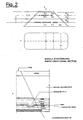
- Figure 2 show views of the plant and the longitudinal section of the bio-cell for whose preparation, on a concrete base coated with a sheet of HDPE, a layer of gravel of an area equal to 5 x 4 m and a thickness of 15 cm, and a layer of sand with a thickness of about 10 cm, were arranged in succession.
- a sheet of non-woven fabric was deposited on this material. It was covered with a layer of sand and a layer of gravel, in which the collection pipes of the percolated product were housed. A layer of sand and a sheet of non-woven fabric were then superimposed.
- Eight 1" pipes were arranged vertically to house the sensors for hydrocarbons, oxygen and humidity (letters a ⁇ g of the longitudinal section).
- a first row of 4 pipes were installed, for the air injection, consisting of fissured PVC pipes enveloped in sleeves of non-woven fabric (on the level of the " ⁇ " plane of figure 2).
- a further 40 cm of amended and fertilized soil were stratified, so as to create a truncated pyramid mound on which the first row of 4 water injection pipes were installed, consisting of a fissured PVC pipe enveloped by a sleeve of non-woven fabric (plane "C").
- the probes for monitoring the interstitial gases were inserted in the 8 specific lodgings: they were connected to the data acquisition and control system of the actuators for the inlet of air and water.
- the whole visible surface was covered, in succession, with a sheet of non-woven fabric, 30 cm of straw and a sheet of HDPE.
- the air pipes were connected to two collectors and these to the 5 m 3 reservoir, fed by the windmill with characteristics analogous to those specified in Example 1.
- the air flow at the outlet of the reservoir had a maximum pressure of a few metres of water column, sufficient to overcome the pressure drops of the line and section of the ground crossed. This flow was distributed among the collectors and subsequently among the various consumption points according to flow-rates established by the control system with characteristics analogous to what is described in Example 1.
- the percolate was collected, through gravitational drop, in a 2 m 3 underground reservoir.
- a pump allowed the water to be re-conveyed to the relative distribution system.
- the water which was progressively evaporated was reintegrated by means of the periodic addition of tap or well water.
- the remediation was initiated by opening the air and water inlet valves.
- the air flow-rate at 6 points was regulated to a value ranging from 2.4 to 3.6 Nm 3 /h whereas the maximum water flow-rate proved to be equal to 550 litres/day (400 in the 4 pipes of level "C” and 150 in the 2 pipes of level “A").
- the probes for monitoring the interstitial gases indicated the concentration of VOC (Volatile Organic Compounds), O 2 and CO 2 .
- FIG. 3 A typical example of the measurements obtained is shown in the graphs of Figure 3, registered by means of the data acquisition system and transmitted via modem in real time.
- the graphs indicate the composition of the interstitial gases in the monitoring points A, B and C of Figure 2.
- the redox potential rapidly reached and was subsequently maintained at values higher than 250 mV, indicating favourable conditions for the growth of aerobic microbial flora.
Landscapes
- Engineering & Computer Science (AREA)
- Life Sciences & Earth Sciences (AREA)
- Soil Sciences (AREA)
- Environmental & Geological Engineering (AREA)
- Microbiology (AREA)
- Molecular Biology (AREA)
- Health & Medical Sciences (AREA)
- Biomedical Technology (AREA)
- Biotechnology (AREA)
- General Health & Medical Sciences (AREA)
- Hydrology & Water Resources (AREA)
- Water Supply & Treatment (AREA)
- Mycology (AREA)
- Processing Of Solid Wastes (AREA)
- Steroid Compounds (AREA)
- Crystals, And After-Treatments Of Crystals (AREA)
- Mechanical Treatment Of Semiconductor (AREA)
- Biological Treatment Of Waste Water (AREA)
- Carbon And Carbon Compounds (AREA)
- Transition And Organic Metals Composition Catalysts For Addition Polymerization (AREA)
Abstract
Description
- The present invention relates to a process for the remediation of polluted sites.
- More specifically, the present invention relates to a process for the remediation of soil, ground and underground water polluted by compounds of an organic nature.
- Even more specifically, the present invention relates to a process for the remediation of soil, ground and underground water polluted by petroleum distillates such as, for example, gasolines and gas oils, or other biodegradable products with or without a hydrocarbon structure.
- Processes for the remediation of polluted soil are known in literature. In the USA patent 6,109,358, for example, a bioremediation process is described for soil polluted by hydrocarbon residues, which includes continuously aerating the soil at different depths, even below the ground water level, by means of venting heads connected to a reservoir under pressure. The conditions are thus established for favouring the rapid growth of aerobic bacterial flora which will carry out the degradation of the pollutants.
- In order to avoid the drawback of resorting to the use of conventional internal combustion or electric engines for running the compressors, the method of the US patent, envisages the use of the motive power generated by windmills, consisting of one or more windmills connected to the compression-air system. Thanks to this solution, it has been possible to eliminate, or reduce, the disadvantages associated with traditional engines, such as maintenance and/or refueling, which require the often frequent interventions of operators and technical personnel.
- The problem of managing a remediation or bioremediation method of polluted sites in a fully automatic way, in the absence of dedicated personnel, is not in fact resolved by the above-mentioned method of the US patent, as the biodegradation of pollutants requires, in addition to soil ventilation, also the presence of nutrients based on phosphorous and nitrogen, necessary for the development and growth of the aerobic bacterial flora:
- The concentration of the nutrients must be sufficiently high to diminish the demolition times of the polluting molecules and, at the same time, sufficiently low to avoid eutrophication processes of the underground water. The nutrients, usually selected from normal fertilizers for agriculture, must therefore be gradually and periodically added to the soil with the intervention of operators, whose presence consequently re-proposes the drawbacks overcome by the use of windmills.
- The operating costs of a bioremediation site are also highly influenced by the necessity of:
- controlling the humidity of the vadose zone of the soil, which tends, particularly during the period of scarce rain and in the superficial layers of the soil, to be reduced to below the critical threshold for degradation on the part of the micro-organisms;
- providing periodical soil and underground water samplings for monitoring the satisfactory progress of the remediation which, in the case of bioremediation interventions (in situ), can last from 6 months to over three years.
- The Applicants have now found a fully automatic method for drastically reducing the operating costs of the bioremediation of a polluted site, by excluding, or highly reducing, the presence of personnel for the maintenance of the machinery used, controlling the nutrients and humidity level, necessary for a correct biodegradation process, and for periodical verifications. We have therefore found:
- a salt based on phosphorous and nitrogen which, due to its poor solubility in water, very slowly releases its nutrient constituents for bacterial flora, thus enabling it to be accumulated and distributed in the soil in relatively high amounts, without running the risk of polluting the underlying water table and without requiring continuous dosage interventions on the part of external operators;
- an air dosage and distribution system, based on the exploitation of wind energy, capable of making oxygen available in a quantity suitable for acting as a final electron-acceptor for microbiologic oxidation processes of the pollutants;
- an integrated system of sensors capable of issuing signals to a data collection and processing system for the activation/deactivation of the introduction of air into the soil to be reclaimed, the modulation of the air-flow between the different injection points, the activation/deactivation of the irrigation systems of the vadose zone of the site and for monitoring the biodegradation phenomena of the pollutants.
- An objective of the present invention therefore relates to a process for site remediation, such as soil, ground and underground water polluted by biodegradable organic products which comprises:
- a) insertion in the site of a series of venting heads at different depths;
- b) connection of the venting heads to a reservoir containing air under pressure, fed by a compressor driven by a windmill;
- c) distribution of magnesium ammonium phosphate NH4MgPO4 in the site, in a single operation, at the beginning of the treatment, in such a quantity as to guarantee the availability of the amount of nitrogen and phosphorous necessary for the biodegradation process;
- d) installation on site of a series of sensors for monitoring the progress of the biodegradation and for controlling the availability of oxygen and humidity;
- e) connecting the sensors of step d) to data loggers, which, when periodically checked, transmit the acquired data to a collecting and data processing remote station;
- f) regulating the flow-rate of the process fluids and the operating times of the equipment by means of actuators operated from the remote station.
- According to the present invention, the remediation process can be used both in the case of treatment in situ, such as biosparging or bioventing, and in the case of on-site and ex situ treatment, such as bio-cells and land-farming.
- In the case of in situ treatment, the venting heads can be placed above or inside the water table, whereas in the case of on-site and ex situ treatment, they will be situated inside the matrix to be reclaimed. Said heads usually consist of cylindrical, plastic or metallic structures, for example of PVC or stainless steel, wherein at least the terminal part, or the whole interred part, has several holes which allow the compressed air to flow into the soil or to gurgle into the water table. The connections between the venting heads, the air reservoir, the compressor and windmill are of the conventional type and do not require any special equipment.
- The windmill comprises an impeller and mechanisms suitable for transferring the mechanical energy generated by the rotation of the impeller due to the wind, to a shaft connected to the air compressor.
- With a diameter of the impeller ranging from 5 to 7 metres and a wind velocity ranging from 3 to 6 m/sec, an installed power of 0.5 to 3 kW is generally obtained. If a power higher than 3 kW is necessary, impellers with a higher diameter than those indicated, or an appropriate number of windmills operating in parallel, can be used.
- Magnesium ammonium phosphate is a product which is known in scientific literature and can be prepared, for example, by recovering the salt precipitated by mixing in suitable proportions solutions containing ammonium phosphate and magnesium chloride at a pH close to neutrality or slightly alkaline.
- In the case of in situ treatment, the magnesium ammonium phosphate can be distributed onto the surface or positioned at different depths of the contaminated soil, whereas in the case of on-site and ex situ treatment, it can be mixed to the soil to be reclaimed.
- In order to obtain a reduction in pollutants equal to at least 90% of the biodegradation process, magnesium ammonium phosphate is generally used in such quantities as to ensure a C/N/P ratio ranging from 100:5:1 to 300:10:1 wherein C represents the quantity of carbon present in the pollutants, N and P the nitrogen and phosphorous, respectively, necessary for the microbial growth.
- In relation to the concentration of pollutants and that of N and P present in the soil, the possibility of using a mixture of magnesium ammonium phosphate and one or more fertilizers commonly used in agriculture, is evaluated. In order to favour an accurate distribution of the salt into the earth and the gradual and slow release of the nutritive elements, it is preferable to irrigate the soil to be treated with water either coming from a reservoir or wells with the use of pumps driven by the windmill itself.
- Once the venting heads have been installed, the nutrient salt distributed and the windmill activated, the remediation process, object of the present invention, can be monitored with sensors and/or probes which continuously measure the trend of the concentration of the hydrocarbons present in the interstitial gases of the soil and/or in the water table. These sensors are previously inserted into the ground and are capable of determining the presence of hydrocarbons even at extremely low concentrations. Examples of these sensors are described in Italian patent 1,290,063.
- There are numerous useful parameters which can be measured with commercial sensors or probes, for example, the pH, redox potential, temperature of the soil or ground water, concentration of oxygen and carbon dioxide in the interstitial gases in the soil.
- The concentration data revealed by the sensors/probes can be transmitted to a data processing unit in a remote position with respect to the site to be remediated and processed for running and regulating the aeration process of the soil and distribution of the irrigation water. In particular, this operating system requires at least one local and one remote station.
- The local station is capable of receiving a signal from the remote station which allows some of the operating parameters to be varied, such as increases or decreases in the flow-rates of the fluids (air and water). These variations can become operative for example by the use of servo-mechanisms, electrovalves or actuators.
- Some illustrative but non-limiting examples are provided for a better understanding of the present invention and for its embodiment.
- The present example describes the embodiment of a bio-sparging/bioventing plant in situ, according to the procedure of the present invention.
- The site to be remediated had been previously used as a sales point for fuels. The characterization of the soil indicated a contamination of the area relating to underground reservoirs (about 10 x 10 m) at a depth of 5 m from the surface of the ground. The concentration of total hydrocarbons ranged from a few tens to a few hundreds of mgTPH/ kgsoil.
- The water table lies at a depth of 2.5 m. The concentration of hydrocarbons in the water ranged from 200 to 700 ppb.
- A general plant scheme is shown in Figure 1 which, for the sake of simplicity, indicates only two injection points, X-O1 and X-02 respectively, instead of those effectively existing, in a higher number.
- The windmill D-01 allows the wind energy to be converted into mechanical energy. This is a machine which, for a wind velocity of 5 m/s, develops a power equal to 0.6 kW. The windmill has an impeller with a diameter of 6 metres and is housed in a trellis, 12 metres high, anchored to the ground by means of concrete plinths. This equipment is directly coupled, after a multiplication of revs, to the alternative oil-free compressor K-01.
- The compressed air is pumped into the reservoir T-01, having a capacity of 5 m3, and is sent into two main lines consisting, in addition to a series of measuring instruments (T and P) and safety systems, of a pressure reducer which allows the desired flow-rate of air to be obtained at the outlet at a pressure which is sufficient to exceed that at the head which rests on the injection points, and also the pressure drops of the line itself.
- From the main lines, the air flow is divided among the various consumption points (X-01 and X-02) through flexible rapid-connection_couplings. For the remediation of an area of about 10 m x 10 m, 4 air injection points were produced up to a depth of 5.5 m (saturated zone) with a pitch equal to 5 m. A hole of 120 mm was created for each point, in which 3 air injection points with 1" tubes were inserted at different depths.
- The automatic monitoring procedures in the operating phase of the physico-chemical parameters differ between saturated and unsaturated soil. In the former case the following parameters were monitored:
- hydrocarbon trend by means of resistive sensors lined with membranes impermeable to water and permeable to vapours and gases;
- oxygen dissolved in ground water by means of a specific probe also capable of determining the conductivity, redox potential, pH and temperature.
- In the unsaturated soil portion, the following parameters were analyzed by means of special underground sensors:
- hydrocarbon trend by means of resistive sensors lined with membranes impermeable to water and permeable to vapours and gases;
- the oxygen of the interstitial gases;
- the humidity of the ground.
- With the process data collection and processing system (hydrocarbons, oxygen in the ground water and interstitial gases, humidity of the ground) ARC-01, it was possible to act on the automatic valves inserted in the air and water distribution lines, in order to modulate the flow-rates of the relative streams for each line. The air flow-rates of the single consumption points were measured by means of FITOT-01 and FITOT-02 instruments.
- The operating air flow-rates adopted had sufficiently limited values as to prevent the formation of clogging phenomena and minimize the possible desorption action of the volatile pollutants and their conveyance in gaseous phase.
- With respect to the gradual release of nutrient substances, magnesium ammonium phosphate was interred in various points of the saturated ground, by effecting four drillings up to 5.5 m and the portion of the hole from 2.5 to 5.5 m was filled with magnesium ammonium phosphate hexahydrate whereas the portion from 0 to 2.5 m was filled with soil deriving from the drilling action itself.
- For the unsaturated part, on the other hand, as it was not possible to exploit the dispersion and diffusion phenomena in the water table, the periodic irrigation of the surface of the treatment area was effected, thus entrusting the subsequent water percolation with the task of transporting the salt initially dispersed in the uppermost surface layer of the ground.
- The dosage system of the water consisted of the reservoirs T-02 A-B that feed the feeding pipe of one of the pumps P-01 A-B which use compressed air as engine fluid and feed the surface irrigation system X-04. The supply is ensured by the suction of ground water with one of the pumps P-01 A-B from suitable wells (X-03 A-B) situated inside the treatment area or surrounding areas. The irrigation system consisted of 4 sprinklers having an influence radius of 3 m.
- With the sole purpose of validating the approach of the present process, for the first 70 days following the activation of the plant, samplings of soil and water were taken. After a latency period of about 30 days, the initial degradation of the hydrocarbons present in the unsaturated zone, was observed, which after 70 days had diminished by 35%.
- During the intervention, the monitoring/data collection and processing system provided the following indications:
- the trend of the hydrocarbons proved to decrease with time in correspondence with what had been observed with the direct analysis of the ground samples used for the validation;
- the oxygen dissolved in the water of the piezometres inside the treatment area oscillated between 2 and 3 mg/l;
- the nitrogenated sources measured in the water of the piezometres inside the treatment area proved to have increased by 1.0 mg/l, thus confirming the slow release of the nutrients used;
- analogous measurements in the water of the piezometres outside the treatment area showed no significant shifts with respect to the values obtained before the activation of the remediation plant;
- the irrigation system was automatically activated twice.
- A bio-cell was produced for the treatment of 14 m3 of soil contaminated by hydrocarbons (total TPH equal to 22,000 ppm) characterized by a low content of inorganic nutrients (ammonium 0.6 ppm,
nitrate 0 ppm, phosphate 1.7 ppm) necessary for the development of a microbial flora. - Figure 2 show views of the plant and the longitudinal section of the bio-cell for whose preparation, on a concrete base coated with a sheet of HDPE, a layer of gravel of an area equal to 5 x 4 m and a thickness of 15 cm, and a layer of sand with a thickness of about 10 cm, were arranged in succession.
- A sheet of non-woven fabric was deposited on this material. It was covered with a layer of sand and a layer of gravel, in which the collection pipes of the percolated product were housed. A layer of sand and a sheet of non-woven fabric were then superimposed.
- Eight 1" pipes were arranged vertically to house the sensors for hydrocarbons, oxygen and humidity (letters a÷g of the longitudinal section).
- About 40 cm of contaminated soil, previously amended with 20% by volume of bog moss peat and with 200 Kg of magnesium ammonium phosphate hexahydrate, were stratified.
- A first row of 4 pipes were installed, for the air injection, consisting of fissured PVC pipes enveloped in sleeves of non-woven fabric (on the level of the "Δ" plane of figure 2). A further 40 cm of amended and fertilized soil were stratified, so as to create a truncated pyramid mound on which the first row of 4 water injection pipes were installed, consisting of a fissured PVC pipe enveloped by a sleeve of non-woven fabric (plane "C").
- The operations of soil stratification, installation of 2 air pipes (plane "B"), soil stratification and installation of 2 water pipes (plane "A"), were repeated.
- The probes for monitoring the interstitial gases (O2, CO2 and VOC), pH, redox potential, temperature and ground humidity, were inserted in the 8 specific lodgings: they were connected to the data acquisition and control system of the actuators for the inlet of air and water.
- The whole visible surface was covered, in succession, with a sheet of non-woven fabric, 30 cm of straw and a sheet of HDPE.
- The air pipes were connected to two collectors and these to the 5 m3 reservoir, fed by the windmill with characteristics analogous to those specified in Example 1.
- The air flow at the outlet of the reservoir had a maximum pressure of a few metres of water column, sufficient to overcome the pressure drops of the line and section of the ground crossed. This flow was distributed among the collectors and subsequently among the various consumption points according to flow-rates established by the control system with characteristics analogous to what is described in Example 1.
- The percolate was collected, through gravitational drop, in a 2 m3 underground reservoir. A pump allowed the water to be re-conveyed to the relative distribution system.
- The water which was progressively evaporated was reintegrated by means of the periodic addition of tap or well water.
- The remediation was initiated by opening the air and water inlet valves. The air flow-rate at 6 points was regulated to a value ranging from 2.4 to 3.6 Nm3/h whereas the maximum water flow-rate proved to be equal to 550 litres/day (400 in the 4 pipes of level "C" and 150 in the 2 pipes of level "A").
- The probes for monitoring the interstitial gases indicated the concentration of VOC (Volatile Organic Compounds), O2 and CO2.
- A typical example of the measurements obtained is shown in the graphs of Figure 3, registered by means of the data acquisition system and transmitted via modem in real time. The graphs indicate the composition of the interstitial gases in the monitoring points A, B and C of Figure 2.
- The remaining values (T, redox and pH) were also recorded in this system.
- The continuous running of the plant was prolonged for about 170 days and from observing the graphs mentioned above, it can be deduced that:
- in the first 30 days an intense microbial activity was observed, registered by a very distinct oscillation of the O2 and CO2 values; contemporaneously the values registered of the VOC in the interstitial gases showed a clear reduction;
- a second phase, in which a more regular respiration was recorded, as a consequence of a stabilization of the process.
- The pH remained constant within the range of 6-8, without any particular problems.
- The redox potential rapidly reached and was subsequently maintained at values higher than 250 mV, indicating favourable conditions for the growth of aerobic microbial flora.
- With the sole purpose of validating the approach of the present process, a sample of soil was taken every 40 days to analyze the residual concentration of TPH and microbial growth of the oxidizing hydrocarbon autochthon flora: the results are indicated in the table.
Table Days TPH (ppm) Oxidizing hydrocarbon (CFU/g) 0 22,000 on the product as such 1x10⁵ 20,600 on the amended product 40 10,130 1x10⁵ 80 6,840 3x10 6120 3,800 3x10⁶ 160 3,400 3x10⁶ TPH = Total Petroleum Hydrocarbon
CFU = Colony Forming Units
Claims (6)
- A process for the remediation of sites, such as soil, ground and underground water polluted by biodegradable organic products which comprises:a) insertion in the site of a series of venting heads at different depths;b) connection of the venting heads to a reservoir containing air under pressure, fed by a compressor driven by a windmill;c) distribution of magnesium ammonium phosphate NH4MgPO4 in the site, in a single operation, at the beginning of the treatment, in such a quantity as to guarantee the availability of the amount of nitrogen and phosphorous necessary for the biodegradation process;d) installation on site of a series of sensors for monitoring the progress of the biodegradation and for controlling the availability of oxygen and humidity;e) connecting the sensors of step d) to data loggers, which, when periodically checked, transmit the acquired data to a collecting and data processing remote station;f) regulating the flow-rate of the process fluids and the operating times of the equipment by means of actuators operated from the remote station.
- The process according to claim 1, wherein the remediation is applied both in the case of treatment in situ, such as biosparging or bioventing, and in the case of on-site and ex situ treatment such as bio-cells and landfarming.
- The process according to claim 1 or 2, wherein the remediation is effected in situ and the venting heads are positioned above or inside the water table.
- The process according to claim 1 or 2, wherein the remediation is effected on-site and ex situ and the venting heads are arranged inside the matrix to be remediated.
- The process according to any of the previous claims, wherein, in order to obtain a reduction in the pollutants equal to at least 90% of the biodegradation process, magnesium ammonium phosphate is used in such quantities as to ensure a C/N/P ratio ranging from 100:5:1 to 300:10:1 wherein C represents the quantity of carbon present in the pollutants, N and P respectively, the nitrogen and phosphorous necessary for the microbial growth.
- The process according to any of the previous claims, wherein, in order to favour the accurate distribution in the ground and gradual and slow release of magnesium ammonium phosphate, it is preferable to irrigate the soil to be treated with water coming either from a reservoir or from wells with the use of pumps activated by the same windmill.
Priority Applications (1)
| Application Number | Priority Date | Filing Date | Title |
|---|---|---|---|
| SI200230533T SI1446240T1 (en) | 2001-11-23 | 2002-11-22 | Process for the remediation of polluted sites |
Applications Claiming Priority (3)
| Application Number | Priority Date | Filing Date | Title |
|---|---|---|---|
| ITMI20012469 | 2001-11-23 | ||
| IT2001MI002469A ITMI20012469A1 (en) | 2001-11-23 | 2001-11-23 | PROCEDURE FOR THE RECLAMATION OF CONTAMINATED SITES |
| PCT/EP2002/013147 WO2003043755A1 (en) | 2001-11-23 | 2002-11-22 | Process for the remediation of polluted sites |
Publications (2)
| Publication Number | Publication Date |
|---|---|
| EP1446240A1 EP1446240A1 (en) | 2004-08-18 |
| EP1446240B1 true EP1446240B1 (en) | 2007-02-21 |
Family
ID=11448625
Family Applications (1)
| Application Number | Title | Priority Date | Filing Date |
|---|---|---|---|
| EP02779570A Expired - Lifetime EP1446240B1 (en) | 2001-11-23 | 2002-11-22 | Process for the remediation of polluted sites |
Country Status (11)
| Country | Link |
|---|---|
| EP (1) | EP1446240B1 (en) |
| AT (1) | ATE354444T1 (en) |
| AU (1) | AU2002342920A1 (en) |
| CY (1) | CY1106587T1 (en) |
| DE (1) | DE60218330T2 (en) |
| DK (1) | DK1446240T3 (en) |
| ES (1) | ES2282481T3 (en) |
| IT (1) | ITMI20012469A1 (en) |
| PT (1) | PT1446240E (en) |
| SI (1) | SI1446240T1 (en) |
| WO (1) | WO2003043755A1 (en) |
Cited By (1)
| Publication number | Priority date | Publication date | Assignee | Title |
|---|---|---|---|---|
| WO2010106155A3 (en) * | 2009-03-19 | 2011-01-06 | Universiteit Gent | Remediation of polluted materials or sites |
Families Citing this family (3)
| Publication number | Priority date | Publication date | Assignee | Title |
|---|---|---|---|---|
| SI1914016T1 (en) | 2006-10-19 | 2016-01-29 | Societa'italiana Acetilene E Derivati S.I.A.D. S.P.A. In Abbreviated Form Siad S.P.A. | Groundwater decontamination system through in situ injection of oxidant and/or riducent gases |
| US9115307B2 (en) * | 2012-03-31 | 2015-08-25 | The Andersons, Inc. | Soil adherent pellet and active agent delivery with same |
| CN113570230B (en) * | 2021-07-21 | 2022-06-28 | 上海亚新城市建设有限公司 | Contaminated land parcel restoration site informatization management method and system |
Family Cites Families (5)
| Publication number | Priority date | Publication date | Assignee | Title |
|---|---|---|---|---|
| IT1051033B (en) * | 1975-12-03 | 1981-04-21 | Snam Progetti | METHOD FOR THE POLLUTION OF FRESH AND MARINE WATERS FROM OIL |
| US6312605B1 (en) * | 1995-05-05 | 2001-11-06 | William B. Kerfoot | Gas-gas-water treatment for groundwater and soil remediation |
| US5985149A (en) * | 1995-12-08 | 1999-11-16 | Raetz; Richard M. | Bioremediation system |
| US6356205B1 (en) * | 1998-11-30 | 2002-03-12 | General Electric | Monitoring, diagnostic, and reporting system and process |
| US6109358A (en) * | 1999-02-05 | 2000-08-29 | Conor Pacific Environmental Technologies Inc. | Venting apparatus and method for remediation of a porous medium |
-
2001
- 2001-11-23 IT IT2001MI002469A patent/ITMI20012469A1/en unknown
-
2002
- 2002-11-22 AU AU2002342920A patent/AU2002342920A1/en not_active Abandoned
- 2002-11-22 WO PCT/EP2002/013147 patent/WO2003043755A1/en not_active Ceased
- 2002-11-22 PT PT02779570T patent/PT1446240E/en unknown
- 2002-11-22 AT AT02779570T patent/ATE354444T1/en active
- 2002-11-22 DE DE60218330T patent/DE60218330T2/en not_active Expired - Lifetime
- 2002-11-22 DK DK02779570T patent/DK1446240T3/en active
- 2002-11-22 EP EP02779570A patent/EP1446240B1/en not_active Expired - Lifetime
- 2002-11-22 SI SI200230533T patent/SI1446240T1/en unknown
- 2002-11-22 ES ES02779570T patent/ES2282481T3/en not_active Expired - Lifetime
-
2007
- 2007-05-14 CY CY20071100649T patent/CY1106587T1/en unknown
Cited By (1)
| Publication number | Priority date | Publication date | Assignee | Title |
|---|---|---|---|---|
| WO2010106155A3 (en) * | 2009-03-19 | 2011-01-06 | Universiteit Gent | Remediation of polluted materials or sites |
Also Published As
| Publication number | Publication date |
|---|---|
| DE60218330D1 (en) | 2007-04-05 |
| WO2003043755A1 (en) | 2003-05-30 |
| EP1446240A1 (en) | 2004-08-18 |
| DE60218330T2 (en) | 2007-10-31 |
| SI1446240T1 (en) | 2007-08-31 |
| ES2282481T3 (en) | 2007-10-16 |
| ATE354444T1 (en) | 2007-03-15 |
| PT1446240E (en) | 2007-05-31 |
| AU2002342920A1 (en) | 2003-06-10 |
| DK1446240T3 (en) | 2007-06-04 |
| CY1106587T1 (en) | 2012-01-25 |
| ITMI20012469A1 (en) | 2003-05-23 |
Similar Documents
| Publication | Publication Date | Title |
|---|---|---|
| US5753494A (en) | Method and apparatus for treating contaminated soils with ozone | |
| US6024513A (en) | Aerobic landfill bioreactor | |
| US4576717A (en) | Process for denitrifying subterreanean waters to make them potable | |
| US11180394B2 (en) | Optimally-controlled hybrid phytoremediation system | |
| US6268205B1 (en) | Subsurface decontamination method | |
| US5738703A (en) | Method to produce a substitute for peat moss | |
| US7404899B2 (en) | Water treatment system | |
| CN102774965A (en) | In-situ repair system for treating pollution of underground water | |
| US6866781B2 (en) | Direct oxygen injection groundwater remediation method and system | |
| US20030196375A1 (en) | Method of producing deep-rooted trees for phytoremediation applications | |
| CN213763431U (en) | Pollute good oxygen biological repair system of soil normal position | |
| US20030155309A1 (en) | Process and system for the self-regulated remediation of groundwater | |
| US7572378B2 (en) | Recycled irrigation water treatment system including reverse osmosis | |
| KR101952612B1 (en) | IOT based real time monitoring and automatic control system of contaminated soil purification equipment | |
| KR100267578B1 (en) | Aerobic degradation of organic municipal solid waste in landfills | |
| US6955765B2 (en) | Recycled irrigation water treatment system | |
| EP1446240A1 (en) | Process for the remediation of polluted sites | |
| Kardos | Renovation of secondary effluent for reuse as a water resource | |
| US6517288B2 (en) | Direct oxygen injection groundwater remediation method and system | |
| EP1399275B1 (en) | Method and device for accelerating the decomposition of biogenic organic matter in refuse disposal sites | |
| KR20070118380A (en) | Simultaneous Ground Purification of Oil and Organic Pollution in Soil and Groundwater by Controlling Pressure and Pressure Using Horizontal Piping | |
| CN213591397U (en) | Biological pile for repairing petroleum hydrocarbon polluted soil | |
| EP1550519B1 (en) | Process and apparatus for in-situ remediation of contaminated underground flowing water | |
| US6719904B2 (en) | Enhanced dissolved oxygen groundwater remediation method and system | |
| DE3880148T2 (en) | METHOD FOR SITU BIODEGRADING OF SOIL POLLUTED WITH HYDROCARBONS. |
Legal Events
| Date | Code | Title | Description |
|---|---|---|---|
| PUAI | Public reference made under article 153(3) epc to a published international application that has entered the european phase |
Free format text: ORIGINAL CODE: 0009012 |
|
| 17P | Request for examination filed |
Effective date: 20040503 |
|
| AK | Designated contracting states |
Kind code of ref document: A1 Designated state(s): AT BE BG CH CY CZ DE DK EE ES FI FR GB GR IE IT LI LU MC NL PT SE SK TR |
|
| AX | Request for extension of the european patent |
Extension state: AL LT LV MK RO SI |
|
| GRAP | Despatch of communication of intention to grant a patent |
Free format text: ORIGINAL CODE: EPIDOSNIGR1 |
|
| GRAS | Grant fee paid |
Free format text: ORIGINAL CODE: EPIDOSNIGR3 |
|
| GRAA | (expected) grant |
Free format text: ORIGINAL CODE: 0009210 |
|
| RAP1 | Party data changed (applicant data changed or rights of an application transferred) |
Owner name: ENI S.P.A. |
|
| AK | Designated contracting states |
Kind code of ref document: B1 Designated state(s): AT BE BG CH CY CZ DE DK EE ES FI FR GB GR IE IT LI LU MC NL PT SE SK TR |
|
| AX | Request for extension of the european patent |
Extension state: AL LT LV MK RO SI |
|
| REG | Reference to a national code |
Ref country code: GB Ref legal event code: FG4D |
|
| REG | Reference to a national code |
Ref country code: CH Ref legal event code: EP |
|
| REF | Corresponds to: |
Ref document number: 60218330 Country of ref document: DE Date of ref document: 20070405 Kind code of ref document: P |
|
| REG | Reference to a national code |
Ref country code: IE Ref legal event code: FG4D |
|
| REG | Reference to a national code |
Ref country code: PT Ref legal event code: SC4A Free format text: AVAILABILITY OF NATIONAL TRANSLATION Effective date: 20070517 |
|
| REG | Reference to a national code |
Ref country code: SE Ref legal event code: TRGR |
|
| REG | Reference to a national code |
Ref country code: CH Ref legal event code: NV Representative=s name: A. BRAUN, BRAUN, HERITIER, ESCHMANN AG PATENTANWAE |
|
| REG | Reference to a national code |
Ref country code: GR Ref legal event code: EP Ref document number: 20070401430 Country of ref document: GR |
|
| ET | Fr: translation filed | ||
| REG | Reference to a national code |
Ref country code: ES Ref legal event code: FG2A Ref document number: 2282481 Country of ref document: ES Kind code of ref document: T3 |
|
| PLBE | No opposition filed within time limit |
Free format text: ORIGINAL CODE: 0009261 |
|
| STAA | Information on the status of an ep patent application or granted ep patent |
Free format text: STATUS: NO OPPOSITION FILED WITHIN TIME LIMIT |
|
| 26N | No opposition filed |
Effective date: 20071122 |
|
| REG | Reference to a national code |
Ref country code: EE Ref legal event code: HC1A Ref document number: E001199 Country of ref document: EE |
|
| REG | Reference to a national code |
Ref country code: CH Ref legal event code: PFA Owner name: ENI S.P.A. Free format text: ENI S.P.A.#PIAZZALE ENRICO MATTEI 1#00144 ROMA (IT) -TRANSFER TO- ENI S.P.A.#PIAZZALE ENRICO MATTEI 1#00144 ROMA (IT) |
|
| REG | Reference to a national code |
Ref country code: EE Ref legal event code: HC1A Ref document number: E001199 Country of ref document: EE |
|
| PGFP | Annual fee paid to national office [announced via postgrant information from national office to epo] |
Ref country code: AT Payment date: 20101103 Year of fee payment: 9 Ref country code: DK Payment date: 20101125 Year of fee payment: 9 Ref country code: EE Payment date: 20101103 Year of fee payment: 9 Ref country code: FR Payment date: 20101202 Year of fee payment: 9 Ref country code: IE Payment date: 20101124 Year of fee payment: 9 Ref country code: NL Payment date: 20101123 Year of fee payment: 9 |
|
| PGFP | Annual fee paid to national office [announced via postgrant information from national office to epo] |
Ref country code: BG Payment date: 20101129 Year of fee payment: 9 Ref country code: CH Payment date: 20101124 Year of fee payment: 9 Ref country code: CZ Payment date: 20101112 Year of fee payment: 9 Ref country code: DE Payment date: 20101126 Year of fee payment: 9 Ref country code: FI Payment date: 20101126 Year of fee payment: 9 Ref country code: PT Payment date: 20101105 Year of fee payment: 9 Ref country code: SK Payment date: 20101103 Year of fee payment: 9 |
|
| PGFP | Annual fee paid to national office [announced via postgrant information from national office to epo] |
Ref country code: TR Payment date: 20101105 Year of fee payment: 9 Ref country code: GB Payment date: 20101124 Year of fee payment: 9 Ref country code: GR Payment date: 20101129 Year of fee payment: 9 Ref country code: SE Payment date: 20101126 Year of fee payment: 9 Ref country code: BE Payment date: 20101117 Year of fee payment: 9 |
|
| PGFP | Annual fee paid to national office [announced via postgrant information from national office to epo] |
Ref country code: MC Payment date: 20110118 Year of fee payment: 9 |
|
| PGFP | Annual fee paid to national office [announced via postgrant information from national office to epo] |
Ref country code: LU Payment date: 20110201 Year of fee payment: 9 |
|
| PGFP | Annual fee paid to national office [announced via postgrant information from national office to epo] |
Ref country code: ES Payment date: 20101125 Year of fee payment: 9 |
|
| PGFP | Annual fee paid to national office [announced via postgrant information from national office to epo] |
Ref country code: CY Payment date: 20110131 Year of fee payment: 9 |
|
| REG | Reference to a national code |
Ref country code: PT Ref legal event code: MM4A Free format text: LAPSE DUE TO NON-PAYMENT OF FEES Effective date: 20120522 |
|
| BERE | Be: lapsed |
Owner name: ENI S.P.A. Effective date: 20111130 |
|
| REG | Reference to a national code |
Ref country code: NL Ref legal event code: V1 Effective date: 20120601 |
|
| LTLA | Lt: lapse of european patent or patent extension |
Effective date: 20111122 |
|
| PG25 | Lapsed in a contracting state [announced via postgrant information from national office to epo] |
Ref country code: MC Free format text: LAPSE BECAUSE OF NON-PAYMENT OF DUE FEES Effective date: 20111130 |
|
| REG | Reference to a national code |
Ref country code: CH Ref legal event code: PL |
|
| REG | Reference to a national code |
Ref country code: DK Ref legal event code: EBP |
|
| REG | Reference to a national code |
Ref country code: SE Ref legal event code: EUG |
|
| REG | Reference to a national code |
Ref country code: GR Ref legal event code: ML Ref document number: 20070401430 Country of ref document: GR Effective date: 20120605 |
|
| GBPC | Gb: european patent ceased through non-payment of renewal fee |
Effective date: 20111122 |
|
| PG25 | Lapsed in a contracting state [announced via postgrant information from national office to epo] |
Ref country code: SK Free format text: LAPSE BECAUSE OF NON-PAYMENT OF DUE FEES Effective date: 20111122 Ref country code: NL Free format text: LAPSE BECAUSE OF NON-PAYMENT OF DUE FEES Effective date: 20120601 Ref country code: LI Free format text: LAPSE BECAUSE OF NON-PAYMENT OF DUE FEES Effective date: 20111130 Ref country code: CZ Free format text: LAPSE BECAUSE OF NON-PAYMENT OF DUE FEES Effective date: 20111122 Ref country code: EE Free format text: LAPSE BECAUSE OF NON-PAYMENT OF DUE FEES Effective date: 20111130 Ref country code: CH Free format text: LAPSE BECAUSE OF NON-PAYMENT OF DUE FEES Effective date: 20111130 |
|
| REG | Reference to a national code |
Ref country code: SK Ref legal event code: MM4A Ref document number: E 1905 Country of ref document: SK Effective date: 20111122 |
|
| REG | Reference to a national code |
Ref country code: EE Ref legal event code: MM4A Ref document number: E001199 Country of ref document: EE Effective date: 20111130 |
|
| REG | Reference to a national code |
Ref country code: FR Ref legal event code: ST Effective date: 20120731 |
|
| REG | Reference to a national code |
Ref country code: IE Ref legal event code: MM4A |
|
| PG25 | Lapsed in a contracting state [announced via postgrant information from national office to epo] |
Ref country code: GR Free format text: LAPSE BECAUSE OF NON-PAYMENT OF DUE FEES Effective date: 20120605 Ref country code: FI Free format text: LAPSE BECAUSE OF NON-PAYMENT OF DUE FEES Effective date: 20111122 Ref country code: PT Free format text: LAPSE BECAUSE OF NON-PAYMENT OF DUE FEES Effective date: 20120522 Ref country code: BE Free format text: LAPSE BECAUSE OF NON-PAYMENT OF DUE FEES Effective date: 20111130 |
|
| REG | Reference to a national code |
Ref country code: SI Ref legal event code: KO00 Effective date: 20120703 |
|
| REG | Reference to a national code |
Ref country code: DE Ref legal event code: R119 Ref document number: 60218330 Country of ref document: DE Effective date: 20120601 |
|
| PG25 | Lapsed in a contracting state [announced via postgrant information from national office to epo] |
Ref country code: CY Free format text: LAPSE BECAUSE OF NON-PAYMENT OF DUE FEES Effective date: 20111122 |
|
| PG25 | Lapsed in a contracting state [announced via postgrant information from national office to epo] |
Ref country code: DK Free format text: LAPSE BECAUSE OF NON-PAYMENT OF DUE FEES Effective date: 20111130 Ref country code: IE Free format text: LAPSE BECAUSE OF NON-PAYMENT OF DUE FEES Effective date: 20111122 Ref country code: GB Free format text: LAPSE BECAUSE OF NON-PAYMENT OF DUE FEES Effective date: 20111122 Ref country code: SE Free format text: LAPSE BECAUSE OF NON-PAYMENT OF DUE FEES Effective date: 20111123 |
|
| REG | Reference to a national code |
Ref country code: AT Ref legal event code: MM01 Ref document number: 354444 Country of ref document: AT Kind code of ref document: T Effective date: 20111122 |
|
| PG25 | Lapsed in a contracting state [announced via postgrant information from national office to epo] |
Ref country code: FR Free format text: LAPSE BECAUSE OF NON-PAYMENT OF DUE FEES Effective date: 20111130 |
|
| PG25 | Lapsed in a contracting state [announced via postgrant information from national office to epo] |
Ref country code: AT Free format text: LAPSE BECAUSE OF NON-PAYMENT OF DUE FEES Effective date: 20111122 |
|
| PG25 | Lapsed in a contracting state [announced via postgrant information from national office to epo] |
Ref country code: LU Free format text: LAPSE BECAUSE OF NON-PAYMENT OF DUE FEES Effective date: 20111122 |
|
| PG25 | Lapsed in a contracting state [announced via postgrant information from national office to epo] |
Ref country code: DE Free format text: LAPSE BECAUSE OF NON-PAYMENT OF DUE FEES Effective date: 20120601 |
|
| PG25 | Lapsed in a contracting state [announced via postgrant information from national office to epo] |
Ref country code: BG Free format text: LAPSE BECAUSE OF NON-PAYMENT OF DUE FEES Effective date: 20120630 |
|
| REG | Reference to a national code |
Ref country code: ES Ref legal event code: FD2A Effective date: 20131023 |
|
| PG25 | Lapsed in a contracting state [announced via postgrant information from national office to epo] |
Ref country code: TR Free format text: LAPSE BECAUSE OF NON-PAYMENT OF DUE FEES Effective date: 20111122 |
|
| PG25 | Lapsed in a contracting state [announced via postgrant information from national office to epo] |
Ref country code: ES Free format text: LAPSE BECAUSE OF NON-PAYMENT OF DUE FEES Effective date: 20111123 |
|
| PGFP | Annual fee paid to national office [announced via postgrant information from national office to epo] |
Ref country code: IT Payment date: 20191125 Year of fee payment: 18 |
|
| PG25 | Lapsed in a contracting state [announced via postgrant information from national office to epo] |
Ref country code: IT Free format text: LAPSE BECAUSE OF NON-PAYMENT OF DUE FEES Effective date: 20201122 |