EP1445986B1 - Microwave oven, more particularly oven which barbecues food - Google Patents
Microwave oven, more particularly oven which barbecues food Download PDFInfo
- Publication number
- EP1445986B1 EP1445986B1 EP03253745A EP03253745A EP1445986B1 EP 1445986 B1 EP1445986 B1 EP 1445986B1 EP 03253745 A EP03253745 A EP 03253745A EP 03253745 A EP03253745 A EP 03253745A EP 1445986 B1 EP1445986 B1 EP 1445986B1
- Authority
- EP
- European Patent Office
- Prior art keywords
- microwave oven
- food
- container
- skewer
- oven according
- Prior art date
- Legal status (The legal status is an assumption and is not a legal conclusion. Google has not performed a legal analysis and makes no representation as to the accuracy of the status listed.)
- Expired - Lifetime
Links
Images


Classifications
-
- F—MECHANICAL ENGINEERING; LIGHTING; HEATING; WEAPONS; BLASTING
- F24—HEATING; RANGES; VENTILATING
- F24C—DOMESTIC STOVES OR RANGES ; DETAILS OF DOMESTIC STOVES OR RANGES, OF GENERAL APPLICATION
- F24C15/00—Details
- F24C15/18—Arrangement of compartments additional to cooking compartments, e.g. for warming or for storing utensils or fuel containers; Arrangement of additional heating or cooking apparatus, e.g. grills
-
- H—ELECTRICITY
- H05—ELECTRIC TECHNIQUES NOT OTHERWISE PROVIDED FOR
- H05B—ELECTRIC HEATING; ELECTRIC LIGHT SOURCES NOT OTHERWISE PROVIDED FOR; CIRCUIT ARRANGEMENTS FOR ELECTRIC LIGHT SOURCES, IN GENERAL
- H05B6/00—Heating by electric, magnetic or electromagnetic fields
- H05B6/64—Heating using microwaves
- H05B6/6408—Supports or covers specially adapted for use in microwave heating apparatus
-
- Y—GENERAL TAGGING OF NEW TECHNOLOGICAL DEVELOPMENTS; GENERAL TAGGING OF CROSS-SECTIONAL TECHNOLOGIES SPANNING OVER SEVERAL SECTIONS OF THE IPC; TECHNICAL SUBJECTS COVERED BY FORMER USPC CROSS-REFERENCE ART COLLECTIONS [XRACs] AND DIGESTS
- Y10—TECHNICAL SUBJECTS COVERED BY FORMER USPC
- Y10S—TECHNICAL SUBJECTS COVERED BY FORMER USPC CROSS-REFERENCE ART COLLECTIONS [XRACs] AND DIGESTS
- Y10S99/00—Foods and beverages: apparatus
- Y10S99/14—Induction heating
Definitions
- the present invention relates to microwave ovens, and more particularly, to a microwave oven which barbecues food.
- a conventional microwave oven food is barbecue cooked by skewering the food on a skewer, placing the skewered food in a cooking cavity of the microwave oven, placing an oil collecting tray on a bottom of the cooking cavity, and starting a barbecue operation of the microwave oven.
- a motor connected to the skewer is operated to rotate the food skewered on the skewer, and the food is barbecued by microwaves irradiated from a magnetron and/or heat generated from a heater of the microwave oven.
- US 4,409,452 discloses a microwave oven having a skewer upon which food may be cooked.
- US 4,717,802 discloses a portable rotisserie assembly for use in a microwave oven.
- the assembly comprises either a spot or a drumlike container for holding the food.
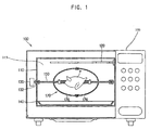
- FIG. 1 shows a sectional view of a microwave oven according to an embodiment of the present invention.
- the microwave oven 100 includes an inner casing 110 which defines a cooking cavity 115 provided in a cabinet 105 of the microwave oven.
- a heater 120 is mounted to an upper portion of the cooking cavity 115 defined by the inner casing 110 to generate heat.
- Two brackets 132 are mounted to respective sidewalls of the inner casing 110 to support a main skewer 150, which is inserted through food P to hold the food P.
- a motor 130 is connected at its motor shaft to one of the brackets 132. By an operation of the motor 130, the food P skewered on the main skewer 150 is rotated.
- An oil collecting tray 140 is seated on a lower portion of the cooking cavity 115 to collect oil produced from the food P.
- the microwave oven 100 further includes a container 170.
- the container 170 is provided at a position between the heater 120 and the oil collecting tray 140, and contains the food P therein.
- Several oil drain holes 176 are formed on the container 170 to discharge the oil produced from the food P to the outside of the container 170. The oil discharged through the oil drain holes 176 drops to the oil collecting tray 140.
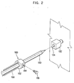
- FIG 2 shows a sub-skewer 160 of the microwave oven shown in Figure 1 .
- the sub-skewer 160 prevents the main skewer 150 from being idly rotated.
- the sub-skewer 160 has a body 162 with a screw hole 164 and one or more needles 166.
- the body 162 is fitted over the main skewer 150.
- the screw hole 164 is formed at a predetermined portion of the body 162.
- the needles 166 are pointed at their respective front ends.
- a bolt 168 is tightened into the screw hole 164 to fasten the body 162 of the sub-skewer 160 to the main skewer 150.
- the main skewer 150 is inserted at an end thereof into a hole 134 which is formed at a side of each bracket 132. Where the motor 130 connected to one of the brackets 132 is operated, the bracket 132 is rotated to rotate the main skewer 150.
- Figure 3 shows the container 170 of the microwave shown in Figure 1 .
- the container 170 is provided with first and second casings 172 and 174 to receive the food P therein.
- a through hole 173 is provided at each of the first and second casings 172 and 174.
- the main skewer 150 passes through the container 170 through the through holes 173.
- an oil drain hole 176 is provided at each of the first and second casings 172 and 174 to discharge oil produced from the food P, during a cooking operation, to the outside of the container 170.
- the first and second casings 172 and 174 each have an oval hemispherical shape, and are assembled with each other to form the container 170. That is, the first casing 172 is stepped inward along an edge of an open side thereof to form a first bent part 179a. The second casing 174 is bent outward along an edge of an open side thereof to form a second bent part 179b. The first and second casings 172 and 174 are arranged in such a way that the first bent part 179a of the first casing 172 is in contact with the second bent part 179b of the second casing 174 while a hole 177a of the first casing 172 is aligned with a hole 177b of the second casing 174. Thereafter, the first and second casings 172 and 174 are assembled with each other by a bolt 178 tightened into the holes 177a and 177b.
- Figure 4 shows a container 180 of a microwave oven according to another embodiment of the present invention.
- the container 180 is provided with first and second casings 182 and 184 to receive food (not shown) therein.
- a through hole 183 is provided at each of the first and second casings 182 and 184.
- a main skewer 150 shown in Figure 1 may pass through the container 180 through the through holes 183.
- An oil drain hole 186 is provided at each of the first and second casings 182 and 184 to discharge oil produced from the food, during a cooking operation, to the outside of the container 180.
- the first and second casings 182 and 184 each have an oval hemispherical shape.
- An external thread 188a is provided along an outer surface of a first bent part 189a which is stepped inward at an open side of the first casing 182.
- An internal thread 188b is provided along an inner surface of a second bent part 189b which is bent outward along an edge of an open side of the second casing 184.
- the external thread 188a of the first casing 182 engages with the internal thread 188b of the second casing 184 to assemble the first and second casings 182 and 184 with each other.
- the food P is skewered on the main skewer 150.
- Two sub-skewers 160 are fitted over both sides of the main skewer 150, respectively, to prevent the main skewer 150 from being idly rotated.
- the needles 166 of each sub-skewer 160 is inserted through the food P.
- the body 162 of each sub-skewer 160 is fastened to the main skewer 150 using the bolt 168.
- the first and second casings 172 and 174 of the container 170, or the first and second casings 182 and 184 of the container 180 are installed on the main skewer 150 to receive the food P in the container 170 or 180.
- the first and second casings 172 and 174, or 182 and 184 are assembled with each other to form the container 170 or 180.
- both ends of the main skewer 150 are inserted into the respective brackets 132.
- the heater 120 and/or the magnetron (not shown) is operated to generate heat and/or microwaves.
- a cooking operation thereof is carried out using the heat and/or the microwaves while the motor 130 is rotated.
- the brackets 132 are rotated by the operation of the motor 130. Accordingly, the main skewer 150, which is inserted into the brackets 132, the food P, and the container 170 or 180 are simultaneously rotated.
- oil produced from the food P due to the heat generated from the heater 120 or the microwaves irradiated from the magnetron, is discharged through the oil drain holes 176 or 186.
- the present invention provides a microwave oven having a container which contains food therein, and prevents oil produced from the food, during for example, a barbecuing operation, from being spattered on a cooking cavity of the microwave oven. Additionally, the microwave oven is provided so as to easily remove the container from the microwave oven where the barbecuing operation is completed. Accordingly, an interior of the cooking cavity is more easily cleaned, as compared to a conventional microwave oven.
Landscapes
- Physics & Mathematics (AREA)
- Electromagnetism (AREA)
- Engineering & Computer Science (AREA)
- Chemical & Material Sciences (AREA)
- Combustion & Propulsion (AREA)
- Mechanical Engineering (AREA)
- General Engineering & Computer Science (AREA)
- Baking, Grill, Roasting (AREA)
- Electric Ovens (AREA)
Description
- The present invention relates to microwave ovens, and more particularly, to a microwave oven which barbecues food.
- Generally, with a conventional microwave oven, food is barbecue cooked by skewering the food on a skewer, placing the skewered food in a cooking cavity of the microwave oven, placing an oil collecting tray on a bottom of the cooking cavity, and starting a barbecue operation of the microwave oven. In this case, a motor connected to the skewer is operated to rotate the food skewered on the skewer, and the food is barbecued by microwaves irradiated from a magnetron and/or heat generated from a heater of the microwave oven.
- However, where the food skewered on the skewer is barbecued, a portion of oil produced from the food does not drop to the oil collecting tray. Rather, it is splattered on an inner wall of the cooking cavity due to the heat generated from the heater or the microwaves. In this case, the inner wall of the cooking cavity, as well as brackets which hold the skewer, is stained with the oil that is later hardened. Thus, it is difficult and time consuming to clean the interior of the cooking cavity to remove the oil after a cooking operation thereof. Furthermore, since the hardened oil is more difficult to remove/clean, the interior of the cooking must be cleaned soon after the cooking operation and more frequently cleaned, thereby inconveniencing a user.
-
US 4,409,452 discloses a microwave oven having a skewer upon which food may be cooked. -
US 4,717,802 discloses a portable rotisserie assembly for use in a microwave oven. The assembly comprises either a spot or a drumlike container for holding the food. - It is an aim of the present invention to provide a microwave oven which is designed to avoid or reduce oil produced from food from being spattered on an inner wall of a cooking cavity, thus allowing a clean surface of the inner wall to be easily maintained.
- Other aims and advantages of the invention will be set forth in part in the description which follows and, in part, will be obvious from the description, or may be learned by practice of the invention.
- According to the present invention there is provided an apparatus and method as set forth in the appended claims. Preferred features of the invention will be apparent from the dependent claims, and the description which follows.
- For a better understanding of the invention, and to show how embodiments of the same may be carried into effect, reference will now be made, by way of example, to the accompanying diagrammatic drawings in which:
-
Figure 1 is a sectional view of a microwave oven according to an embodiment of the present invention; -
Figure 2 is a partial perspective view of a skewer, which is inserted through food, utilized in the microwave oven shown inFigure 1 ; -
Figure 3 is an exploded perspective view of a container of the microwave oven shown inFigure 1 ; and -
Figure 4 is an exploded perspective view of a container of a microwave oven according to another embodiment of the present invention. -
Figure 1 shows a sectional view of a microwave oven according to an embodiment of the present invention. As shown inFigure 1 , themicrowave oven 100 includes aninner casing 110 which defines acooking cavity 115 provided in acabinet 105 of the microwave oven. Aheater 120 is mounted to an upper portion of thecooking cavity 115 defined by theinner casing 110 to generate heat. Twobrackets 132 are mounted to respective sidewalls of theinner casing 110 to support amain skewer 150, which is inserted through food P to hold the foodP. A motor 130 is connected at its motor shaft to one of thebrackets 132. By an operation of themotor 130, the food P skewered on themain skewer 150 is rotated. Anoil collecting tray 140 is seated on a lower portion of thecooking cavity 115 to collect oil produced from the food P. - The
microwave oven 100 further includes acontainer 170. Thecontainer 170 is provided at a position between theheater 120 and theoil collecting tray 140, and contains the food P therein. Several oil drain holes 176 are formed on thecontainer 170 to discharge the oil produced from the food P to the outside of thecontainer 170. The oil discharged through the oil drain holes 176 drops to theoil collecting tray 140. -
Figure 2 shows asub-skewer 160 of the microwave oven shown inFigure 1 . The sub-skewer 160 prevents themain skewer 150 from being idly rotated. Thesub-skewer 160 has abody 162 with ascrew hole 164 and one ormore needles 166. Thebody 162 is fitted over themain skewer 150. Thescrew hole 164 is formed at a predetermined portion of thebody 162. Theneedles 166 are pointed at their respective front ends. Abolt 168 is tightened into thescrew hole 164 to fasten thebody 162 of thesub-skewer 160 to themain skewer 150. - The
main skewer 150 is inserted at an end thereof into ahole 134 which is formed at a side of eachbracket 132. Where themotor 130 connected to one of thebrackets 132 is operated, thebracket 132 is rotated to rotate themain skewer 150. -
Figure 3 shows thecontainer 170 of the microwave shown inFigure 1 . Thecontainer 170 is provided with first andsecond casings hole 173 is provided at each of the first andsecond casings main skewer 150 passes through thecontainer 170 through the throughholes 173. - As shown in
Figure 3 , anoil drain hole 176 is provided at each of the first andsecond casings container 170. - The first and
second casings container 170. That is, thefirst casing 172 is stepped inward along an edge of an open side thereof to form afirst bent part 179a. Thesecond casing 174 is bent outward along an edge of an open side thereof to form asecond bent part 179b. The first andsecond casings first bent part 179a of thefirst casing 172 is in contact with thesecond bent part 179b of thesecond casing 174 while ahole 177a of thefirst casing 172 is aligned with ahole 177b of thesecond casing 174. Thereafter, the first andsecond casings bolt 178 tightened into theholes -
Figure 4 shows acontainer 180 of a microwave oven according to another embodiment of the present invention. Thecontainer 180 is provided with first andsecond casings hole 183 is provided at each of the first andsecond casings main skewer 150 shown inFigure 1 may pass through thecontainer 180 through the throughholes 183. - An
oil drain hole 186 is provided at each of the first andsecond casings container 180. - The first and
second casings external thread 188a is provided along an outer surface of afirst bent part 189a which is stepped inward at an open side of thefirst casing 182. Aninternal thread 188b is provided along an inner surface of asecond bent part 189b which is bent outward along an edge of an open side of thesecond casing 184. Theexternal thread 188a of thefirst casing 182 engages with theinternal thread 188b of thesecond casing 184 to assemble the first andsecond casings - An operation of a microwave oven according to the present invention will be described below with reference to the drawings.
- The food P is skewered on the
main skewer 150. Twosub-skewers 160 are fitted over both sides of themain skewer 150, respectively, to prevent themain skewer 150 from being idly rotated. In this case, theneedles 166 of eachsub-skewer 160 is inserted through the food P. Subsequently, thebody 162 of eachsub-skewer 160 is fastened to themain skewer 150 using thebolt 168. Afterwards, the first andsecond casings container 170, or the first andsecond casings container 180 are installed on themain skewer 150 to receive the food P in thecontainer second casings container main skewer 150 are inserted into therespective brackets 132. - Where a barbecue cooking mode is set, the
heater 120 and/or the magnetron (not shown) is operated to generate heat and/or microwaves. A cooking operation thereof is carried out using the heat and/or the microwaves while themotor 130 is rotated. Thebrackets 132 are rotated by the operation of themotor 130. Accordingly, themain skewer 150, which is inserted into thebrackets 132, the food P, and thecontainer - As the food P is cooked, oil, produced from the food P due to the heat generated from the
heater 120 or the microwaves irradiated from the magnetron, is discharged through the oil drain holes 176 or 186. The oil, discharged through the oil drain holes 176 or 186, drops to theoil collecting tray 140. - As described above, the present invention provides a microwave oven having a container which contains food therein, and prevents oil produced from the food, during for example, a barbecuing operation, from being spattered on a cooking cavity of the microwave oven. Additionally, the microwave oven is provided so as to easily remove the container from the microwave oven where the barbecuing operation is completed. Accordingly, an interior of the cooking cavity is more easily cleaned, as compared to a conventional microwave oven.
- Although a few preferred embodiments have been shown and described, it will be appreciated by those skilled in the art that various changes and modifications might be made without departing from the scope of the invention, as defined in the appended claims.
Claims (15)
- A microwave oven to cook food, comprising:a cooking cavity (115);a skewer (150) which is insertable through food to thereby hold the food; andcharacterised in that the microwave oven further comprises a container (170) adapted to be arranged about the skewer (150) and operable to contain food therein so as not to stain an inner wall of the cooking cavity (115) with oil produced from the said food during a cooking operation of the microwave oven.
- The microwave oven according to claim 1, wherein the container (170) includes an oil drain hole (176) which is provided at a predetermined portion of the container (170) so as to discharge oil produced from food during a cooking operation to an outside of the container (170) through the oil drain hole (176).
- The microwave oven according to claim 1 or 2, further comprising an oil collecting tray (140) operable to collect oil discharged from the container (170).
- The microwave oven according to any preceding claim, further comprising a motor (130) operable to rotate the food, in use, wherein the container (170) is rotatable by operation of the motor (130).
- The microwave oven according to claim 4, further comprising one or more brackets (132) which support the skewer (150), wherein the motor (130) is connected to one of the brackets and is operable to rotate the container (170) along with the skewer (150), in use.
- The microwave oven according to claim 5, wherein the skewer (150) includes:a main skewer (150) having ends corresponding to respective openings of the brackets; andone or more sub-skewers (160) which are insertable through food to thereby prevent the main skewer (150) from being idly rotated, in use.
- The microwave oven according to claim 6, wherein the each of the sub-skewers (160) includes:a body (162) having one or more protruding needles that are insertable into food; anda securing unit (168,164) which fastens the body (162) to the main skewer (150).
- The microwave oven according to any preceding claim, wherein the container (170) comprises first and second casings (172,174) each comprising an opening at a side thereof to surround the food, the first and second casings (172,174) being assemblable with each other to form the container (170).
- The microwave oven according to claim 8, wherein the first and second casings (172,174) include:first and second holes (177a,177b) which are formed at predetermined portions of the first and second casings (172,174) of the container (170), respectively; anda bolt (178) which is tightened into the first and second holes (177a,177b) so as to assemble the first and second casings (172,174) with each other.
- The microwave oven according to claim 8 or 9, wherein:the first casing (182) includes an internal thread (188b) which is provided along an edge of the open side of the first casing (182), and the second casing (184) includes an external thread (188a) which is provided along an edge of the open side of the second casing (184) and is operable to engage with the internal thread (188b) of the first casing (182) to assemble the first and second casings (182,184) with each other.
- The microwave oven according to claim 8, 9 or 10, wherein the first and second casings (172,174,182,184) include corresponding through holes (173,183) which allow the main skewer (150) to pass therethrough.
- The microwave oven according to any preceding claim, wherein the container (170) is removably provided in the cooking cavity (115).
- The microwave oven according to any preceding claim, further comprising a heating unit (120) which includes a magnetron that generates microwaves to cook the food.
- The microwave oven according to claim 13, wherein the heating unit (120) further includes a heater (120) which provides heat to cook the food.
- The microwave oven according to claim 13 or 14, wherein the food is rotated along with the skewer (150) during an operation of the heating unit (120).
Applications Claiming Priority (2)
| Application Number | Priority Date | Filing Date | Title |
|---|---|---|---|
| KR1020030007737A KR20040071835A (en) | 2003-02-07 | 2003-02-07 | Microwave oven |
| KR2003007737 | 2003-02-07 |
Publications (3)
| Publication Number | Publication Date |
|---|---|
| EP1445986A2 EP1445986A2 (en) | 2004-08-11 |
| EP1445986A3 EP1445986A3 (en) | 2006-10-25 |
| EP1445986B1 true EP1445986B1 (en) | 2008-10-29 |
Family
ID=32653349
Family Applications (1)
| Application Number | Title | Priority Date | Filing Date |
|---|---|---|---|
| EP03253745A Expired - Lifetime EP1445986B1 (en) | 2003-02-07 | 2003-06-12 | Microwave oven, more particularly oven which barbecues food |
Country Status (6)
| Country | Link |
|---|---|
| US (1) | US6998593B2 (en) |
| EP (1) | EP1445986B1 (en) |
| JP (1) | JP2004239599A (en) |
| KR (1) | KR20040071835A (en) |
| CN (1) | CN1249385C (en) |
| DE (1) | DE60324381D1 (en) |
Families Citing this family (10)
| Publication number | Priority date | Publication date | Assignee | Title |
|---|---|---|---|---|
| US7478586B2 (en) * | 2004-06-04 | 2009-01-20 | Peacock Myers, P.C. | Rotisserie roaster smoker |
| KR100660683B1 (en) * | 2005-12-13 | 2006-12-21 | 엘지전자 주식회사 | Skewers for microwave oven |
| US7921768B2 (en) * | 2006-04-13 | 2011-04-12 | Products Of Tomorrow, Inc. | Vertical and horizontal oven |
| US8272321B1 (en) * | 2007-12-20 | 2012-09-25 | Capital Cooking Equipment, Inc. | Rotisserie for oven |
| US8847131B2 (en) * | 2008-03-03 | 2014-09-30 | Lee Fang | Microwave oven with rotary cooking apparatus |
| KR101047698B1 (en) | 2008-05-23 | 2011-07-08 | 엘지전자 주식회사 | Microwave |
| US9974414B2 (en) * | 2015-10-29 | 2018-05-22 | Alto-Shaam, Inc. | Oven rack for deflecting grease drippings |
| CN111166197B (en) * | 2019-08-22 | 2022-06-17 | 九阳股份有限公司 | Baking oven |
| JP6881793B1 (en) * | 2020-02-07 | 2021-06-02 | マイクロ波化学株式会社 | Microwave processing device and microwave processing method |
| WO2024021101A1 (en) * | 2022-07-29 | 2024-02-01 | 广东美的厨房电器制造有限公司 | Cooking device |
Family Cites Families (7)
| Publication number | Priority date | Publication date | Assignee | Title |
|---|---|---|---|---|
| US3215338A (en) * | 1963-04-05 | 1965-11-02 | George H Schirmer | Rotisserie grilling container |
| US4717802A (en) * | 1979-06-11 | 1988-01-05 | Plastics, Inc. | Microwave oven rotisserie assembly |
| JPS5710031A (en) * | 1980-06-19 | 1982-01-19 | Hitachi Heating Appliance Co Ltd | Microwave oven |
| JPS5733733A (en) * | 1980-08-07 | 1982-02-23 | Toshiba Corp | High-frequency heating device |
| US4880951A (en) * | 1988-06-03 | 1989-11-14 | General Housewares Corporation | Food preparation kit for use in cooking food in microwave oven or in thermal oven |
| US5057331A (en) * | 1989-01-13 | 1991-10-15 | Levinson Melvin L | Cooking food in a food preparation kit in a microwave and in a thermal oven |
| US6220152B1 (en) * | 1998-12-23 | 2001-04-24 | Chris Baldwin | Barbeque rotisserie enclosure |
-
2003
- 2003-02-07 KR KR1020030007737A patent/KR20040071835A/en not_active Withdrawn
- 2003-05-23 US US10/443,890 patent/US6998593B2/en not_active Expired - Fee Related
- 2003-06-02 CN CNB031384331A patent/CN1249385C/en not_active Expired - Fee Related
- 2003-06-12 DE DE60324381T patent/DE60324381D1/en not_active Expired - Lifetime
- 2003-06-12 EP EP03253745A patent/EP1445986B1/en not_active Expired - Lifetime
- 2003-10-30 JP JP2003371180A patent/JP2004239599A/en active Pending
Also Published As
| Publication number | Publication date |
|---|---|
| DE60324381D1 (en) | 2008-12-11 |
| JP2004239599A (en) | 2004-08-26 |
| CN1519508A (en) | 2004-08-11 |
| CN1249385C (en) | 2006-04-05 |
| US20040159656A1 (en) | 2004-08-19 |
| KR20040071835A (en) | 2004-08-16 |
| US6998593B2 (en) | 2006-02-14 |
| EP1445986A3 (en) | 2006-10-25 |
| EP1445986A2 (en) | 2004-08-11 |
Similar Documents
| Publication | Publication Date | Title |
|---|---|---|
| EP1419721B1 (en) | Cooking vessel used with microwave ovens | |
| EP1441569B1 (en) | Microwave oven | |
| KR20070108022A (en) | Heating device and cooking apparatus including the same | |
| US4307285A (en) | Toaster/oven with removable cooking chamber side liners | |
| US20040050841A1 (en) | Microwave oven with toaster | |
| US6998593B2 (en) | Microwave oven with inner container | |
| EP1542512B1 (en) | Cooking apparatus with lamp assembly | |
| US20070101869A1 (en) | Portable rotisserie oven having a removable food holding device with an external handle | |
| EP1424025A1 (en) | Table | |
| JP2903438B2 (en) | Cooker | |
| KR200244055Y1 (en) | Microwave Oven | |
| KR200150949Y1 (en) | Microwave Cooking Accessories | |
| CN223463962U (en) | A post-heating vertical multifunctional air frying device | |
| KR920005661Y1 (en) | A dish for electronic range | |
| EP1389893B1 (en) | Microwave oven and more particularly a door for a microwave oven | |
| JP6917733B2 (en) | Cooker | |
| KR200142129Y1 (en) | Multifunctional Microwave Oven with Drain | |
| KR100270867B1 (en) | Cooking aids for microwave oven | |
| KR200162319Y1 (en) | Microwave oven | |
| KR19980013686A (en) | Auxiliary device for microwave oven skewers | |
| KR19980060303U (en) | Microwave Dish Container | |
| KR100247774B1 (en) | Grilling aids of the microwave oven | |
| KR200162047Y1 (en) | Microwave Oven Grill | |
| KR20060013843A (en) | Cooking chamber separation structure of microwave oven | |
| KR200178153Y1 (en) | Multifunctional Microwave Tray Drainer Structure |
Legal Events
| Date | Code | Title | Description |
|---|---|---|---|
| PUAI | Public reference made under article 153(3) epc to a published international application that has entered the european phase |
Free format text: ORIGINAL CODE: 0009012 |
|
| 17P | Request for examination filed |
Effective date: 20030701 |
|
| AK | Designated contracting states |
Kind code of ref document: A2 Designated state(s): AT BE BG CH CY CZ DE DK EE ES FI FR GB GR HU IE IT LI LU MC NL PT RO SE SI SK TR |
|
| AX | Request for extension of the european patent |
Extension state: AL LT LV MK |
|
| PUAL | Search report despatched |
Free format text: ORIGINAL CODE: 0009013 |
|
| AK | Designated contracting states |
Kind code of ref document: A3 Designated state(s): AT BE BG CH CY CZ DE DK EE ES FI FR GB GR HU IE IT LI LU MC NL PT RO SE SI SK TR |
|
| AX | Request for extension of the european patent |
Extension state: AL LT LV MK |
|
| 17Q | First examination report despatched |
Effective date: 20070207 |
|
| AKX | Designation fees paid |
Designated state(s): DE FR GB |
|
| GRAP | Despatch of communication of intention to grant a patent |
Free format text: ORIGINAL CODE: EPIDOSNIGR1 |
|
| GRAS | Grant fee paid |
Free format text: ORIGINAL CODE: EPIDOSNIGR3 |
|
| GRAA | (expected) grant |
Free format text: ORIGINAL CODE: 0009210 |
|
| AK | Designated contracting states |
Kind code of ref document: B1 Designated state(s): DE FR GB |
|
| REG | Reference to a national code |
Ref country code: GB Ref legal event code: FG4D |
|
| REF | Corresponds to: |
Ref document number: 60324381 Country of ref document: DE Date of ref document: 20081211 Kind code of ref document: P |
|
| PLBE | No opposition filed within time limit |
Free format text: ORIGINAL CODE: 0009261 |
|
| STAA | Information on the status of an ep patent application or granted ep patent |
Free format text: STATUS: NO OPPOSITION FILED WITHIN TIME LIMIT |
|
| 26N | No opposition filed |
Effective date: 20090730 |
|
| PGFP | Annual fee paid to national office [announced via postgrant information from national office to epo] |
Ref country code: GB Payment date: 20140522 Year of fee payment: 12 |
|
| PGFP | Annual fee paid to national office [announced via postgrant information from national office to epo] |
Ref country code: DE Payment date: 20140523 Year of fee payment: 12 |
|
| PGFP | Annual fee paid to national office [announced via postgrant information from national office to epo] |
Ref country code: FR Payment date: 20140522 Year of fee payment: 12 |
|
| REG | Reference to a national code |
Ref country code: DE Ref legal event code: R119 Ref document number: 60324381 Country of ref document: DE |
|
| GBPC | Gb: european patent ceased through non-payment of renewal fee |
Effective date: 20150612 |
|
| REG | Reference to a national code |
Ref country code: FR Ref legal event code: ST Effective date: 20160229 |
|
| PG25 | Lapsed in a contracting state [announced via postgrant information from national office to epo] |
Ref country code: DE Free format text: LAPSE BECAUSE OF NON-PAYMENT OF DUE FEES Effective date: 20160101 Ref country code: GB Free format text: LAPSE BECAUSE OF NON-PAYMENT OF DUE FEES Effective date: 20150612 |
|
| PG25 | Lapsed in a contracting state [announced via postgrant information from national office to epo] |
Ref country code: FR Free format text: LAPSE BECAUSE OF NON-PAYMENT OF DUE FEES Effective date: 20150630 |