EP1445958A1 - Quantization method and system, for instance for video MPEG applications, and computer program product therefor - Google Patents
Quantization method and system, for instance for video MPEG applications, and computer program product therefor Download PDFInfo
- Publication number
- EP1445958A1 EP1445958A1 EP03002443A EP03002443A EP1445958A1 EP 1445958 A1 EP1445958 A1 EP 1445958A1 EP 03002443 A EP03002443 A EP 03002443A EP 03002443 A EP03002443 A EP 03002443A EP 1445958 A1 EP1445958 A1 EP 1445958A1
- Authority
- EP
- European Patent Office
- Prior art keywords
- quantization
- bitrate
- quantized
- coefficient
- signal
- Prior art date
- Legal status (The legal status is an assumption and is not a legal conclusion. Google has not performed a legal analysis and makes no representation as to the accuracy of the status listed.)
- Withdrawn
Links
- 238000013139 quantization Methods 0.000 title claims abstract description 124
- 238000000034 method Methods 0.000 title claims abstract description 62
- 238000004590 computer program Methods 0.000 title claims description 3
- 230000008569 process Effects 0.000 claims abstract description 22
- 238000009826 distribution Methods 0.000 claims description 16
- 230000006870 function Effects 0.000 claims description 10
- 238000001914 filtration Methods 0.000 claims description 6
- 238000009827 uniform distribution Methods 0.000 claims description 5
- 238000011144 upstream manufacturing Methods 0.000 claims description 3
- 239000003607 modifier Substances 0.000 claims 1
- 238000001228 spectrum Methods 0.000 claims 1
- 238000006243 chemical reaction Methods 0.000 abstract description 3
- 230000033001 locomotion Effects 0.000 description 15
- 238000013459 approach Methods 0.000 description 12
- 238000007906 compression Methods 0.000 description 11
- 230000006835 compression Effects 0.000 description 9
- 238000004422 calculation algorithm Methods 0.000 description 7
- 238000010586 diagram Methods 0.000 description 7
- 235000019525 fullness Nutrition 0.000 description 7
- 239000000872 buffer Substances 0.000 description 6
- 238000004364 calculation method Methods 0.000 description 6
- 230000000694 effects Effects 0.000 description 6
- 238000012545 processing Methods 0.000 description 6
- 230000003044 adaptive effect Effects 0.000 description 5
- 230000008901 benefit Effects 0.000 description 5
- 230000005540 biological transmission Effects 0.000 description 5
- 230000000875 corresponding effect Effects 0.000 description 4
- 238000012360 testing method Methods 0.000 description 4
- 239000013598 vector Substances 0.000 description 4
- 238000004891 communication Methods 0.000 description 3
- 238000013441 quality evaluation Methods 0.000 description 3
- 238000003860 storage Methods 0.000 description 3
- 230000002123 temporal effect Effects 0.000 description 3
- 230000009466 transformation Effects 0.000 description 3
- 241001589086 Bellapiscis medius Species 0.000 description 2
- 241001417521 Pomacentridae Species 0.000 description 2
- RTAQQCXQSZGOHL-UHFFFAOYSA-N Titanium Chemical compound [Ti] RTAQQCXQSZGOHL-UHFFFAOYSA-N 0.000 description 2
- 230000009471 action Effects 0.000 description 2
- 230000002411 adverse Effects 0.000 description 2
- 230000008859 change Effects 0.000 description 2
- 238000012937 correction Methods 0.000 description 2
- 230000002596 correlated effect Effects 0.000 description 2
- 230000014509 gene expression Effects 0.000 description 2
- 239000011159 matrix material Substances 0.000 description 2
- 230000000750 progressive effect Effects 0.000 description 2
- 238000004088 simulation Methods 0.000 description 2
- 230000000007 visual effect Effects 0.000 description 2
- 238000012935 Averaging Methods 0.000 description 1
- 102000003712 Complement factor B Human genes 0.000 description 1
- 108090000056 Complement factor B Proteins 0.000 description 1
- 230000006399 behavior Effects 0.000 description 1
- 230000000903 blocking effect Effects 0.000 description 1
- 230000015556 catabolic process Effects 0.000 description 1
- 239000012141 concentrate Substances 0.000 description 1
- 230000001276 controlling effect Effects 0.000 description 1
- 239000013256 coordination polymer Substances 0.000 description 1
- 238000013144 data compression Methods 0.000 description 1
- 230000003247 decreasing effect Effects 0.000 description 1
- 230000006735 deficit Effects 0.000 description 1
- 238000006731 degradation reaction Methods 0.000 description 1
- 230000001419 dependent effect Effects 0.000 description 1
- 230000002708 enhancing effect Effects 0.000 description 1
- 230000001747 exhibiting effect Effects 0.000 description 1
- 238000002474 experimental method Methods 0.000 description 1
- 238000003780 insertion Methods 0.000 description 1
- 230000037431 insertion Effects 0.000 description 1
- 230000010354 integration Effects 0.000 description 1
- 238000005259 measurement Methods 0.000 description 1
- 238000012986 modification Methods 0.000 description 1
- 230000004048 modification Effects 0.000 description 1
- 238000005457 optimization Methods 0.000 description 1
- 238000004091 panning Methods 0.000 description 1
- 238000007781 pre-processing Methods 0.000 description 1
- 230000009257 reactivity Effects 0.000 description 1
- 230000009467 reduction Effects 0.000 description 1
- 230000002441 reversible effect Effects 0.000 description 1
- 230000005654 stationary process Effects 0.000 description 1
- 230000001360 synchronised effect Effects 0.000 description 1
- 230000009897 systematic effect Effects 0.000 description 1
- 238000000844 transformation Methods 0.000 description 1
- 238000013519 translation Methods 0.000 description 1
Images


Classifications
-
- H—ELECTRICITY
- H04—ELECTRIC COMMUNICATION TECHNIQUE
- H04N—PICTORIAL COMMUNICATION, e.g. TELEVISION
- H04N19/00—Methods or arrangements for coding, decoding, compressing or decompressing digital video signals
- H04N19/90—Methods or arrangements for coding, decoding, compressing or decompressing digital video signals using coding techniques not provided for in groups H04N19/10-H04N19/85, e.g. fractals
-
- H—ELECTRICITY
- H04—ELECTRIC COMMUNICATION TECHNIQUE
- H04N—PICTORIAL COMMUNICATION, e.g. TELEVISION
- H04N19/00—Methods or arrangements for coding, decoding, compressing or decompressing digital video signals
- H04N19/10—Methods or arrangements for coding, decoding, compressing or decompressing digital video signals using adaptive coding
- H04N19/102—Methods or arrangements for coding, decoding, compressing or decompressing digital video signals using adaptive coding characterised by the element, parameter or selection affected or controlled by the adaptive coding
- H04N19/124—Quantisation
-
- H—ELECTRICITY
- H04—ELECTRIC COMMUNICATION TECHNIQUE
- H04N—PICTORIAL COMMUNICATION, e.g. TELEVISION
- H04N19/00—Methods or arrangements for coding, decoding, compressing or decompressing digital video signals
- H04N19/10—Methods or arrangements for coding, decoding, compressing or decompressing digital video signals using adaptive coding
- H04N19/102—Methods or arrangements for coding, decoding, compressing or decompressing digital video signals using adaptive coding characterised by the element, parameter or selection affected or controlled by the adaptive coding
- H04N19/124—Quantisation
- H04N19/126—Details of normalisation or weighting functions, e.g. normalisation matrices or variable uniform quantisers
-
- H—ELECTRICITY
- H04—ELECTRIC COMMUNICATION TECHNIQUE
- H04N—PICTORIAL COMMUNICATION, e.g. TELEVISION
- H04N19/00—Methods or arrangements for coding, decoding, compressing or decompressing digital video signals
- H04N19/40—Methods or arrangements for coding, decoding, compressing or decompressing digital video signals using video transcoding, i.e. partial or full decoding of a coded input stream followed by re-encoding of the decoded output stream
Definitions
- the present invention relates to techniques for encoding/transcoding digital video sequences. With the advent of new media, video compression is increasingly being applied. In a video broadcast environment, a variety of channels and supports exist, associated to a variety of standard for content encoding and decoding.
- MPEG a well known acronym for Moving Pictures Experts Group
- An example is the transmission of video signals both for standard television (SDTV) and high definition television (HDTV).
- HDTV demands bit rates up to 40 Mbit/s): MPEG is thus widely used for Set-Top-Box and DVD applications.
- Another example is the transmission over an error prone channel with a very low bitrate (down to 64 Kbit/s) like the Internet and third generation wireless communications terminals.
- quantizer This is a key block in the entire encoding scheme because the quantizer is where the original information is partially lost, as a result of spatial redundancy being removed from the images.
- quantizer also introduces the so called "quantization error", which must be minimized, especially when a re-quantization step takes place as is the case i.a. when a compressed stream is to be re-encoded for a different platform, channel, storage, etc.
- this block is responsible for checking the real output bit-rate generated, and correspondingly adjust the quantization level to meet the output bitrate requirements as needed.
- the MPEG video standard is based on a video compression procedure that exploits the high degree of spatial and temporal correlation existing in natural video sequences.
- an input video sequence is subject to frame reorder at 10 and then fed to a motion estimation block 12 associated with an anchor frames buffer 14.
- Hybrid DPCM/DCT coding removes temporal redundancy using inter-frame motion estimation.
- the residual error images generated at 16 are further processed via a Discrete Cosine Transform (DCT) at 18, which reduces spatial redundancy by decorrelating the pixels within a block and concentrating the energy of the block into a few low order coefficients.
- DCT Discrete Cosine Transform
- VLC variable length coding
- the final bit-stream is produced at a variable and unconstrained bitrate; hence, in order to control it or when the output channel requires a constant bitrate, an output buffer 24 and a feedback bitrate controller block 26, which defines the granularity of scalar quantization, must be added.
- reference number 28 designates a multiplexer adapted for feeding the buffer 24 with either the VLC coded signals or signals derived from the motion estimation block 12, while references 30, 32, and 39 designate an inverse quantizer, an inverse DCT (IDCT) module and a summation node included in the loop encoder to feed the anchor frames buffer 14.
- IDCT inverse DCT
- the MPEG standard defines the syntax and semantics of the output bit-stream OS and the functionality of the decoder. However, the encoder is not strictly standardized: any encoder that produces a valid MPEG bitstream is acceptable.
- Motion estimation is used to evaluate similarities among successive pictures, in order to remove temporal redundancy, i.e. to transmit only the difference among successive pictures.
- block matching motion Estimation (BM-ME) is a common way of extracting the existing similarities among pictures and is the technique selected by the MPEG-2 standard.
- the former is storing, managing, selecting, and delivering different versions of the media objects (images, video, audio, graphics and text) that comprise the multimedia presentations.
- the letter is manipulating the media objects "on the fly", by using, for example, methods for text-to-speech translation, image and video transcoding, media conversion, and summarization.
- Multimedia content delivery thus can be adapted to the wide diversity of client device capabilities in communication, processing storage and display.
- transcoder A device that performs such an operation is called a transcoder.
- Such a device could be placed in a network to help relaying transmissions between different bit rates or could be used as a pre-processing tool to create various versions of the media objects possibly needed as mentioned in the foregoing.
- a DVD movie MPEG-2 encoded at 8 Mbit/s at standard definition may be selected by a user wishing to watch it using a portable wireless device assisted by a CIF display.
- the movie must be MPEG-2 decoded, the picture resolution changed from standard definition to CIF and then MPEG-4 encoded.
- the resulting bitstream at, i.e., 64 Kbit/s is thus adapted to be transmitted over a limited bandwidth error-prone channel, received by the portable device and MPEG-4 decoded for related display.
- the issue is therefore to cleverly adapt the bitrate and the picture resolution of a compressed data stream compliant to a certain video standard (e.g. MPEG-2) to another one (e.g. MPEG-4).
- a widely adopted procedure is to decode the incoming bitstream, optionally to down-sample the decoded images to generate a sequence with a reduced picture size, and then re-encode the sequence with a new encoder configured to achieve the required bitrate.
- requantizer de-quantization followed by a re-quantization step
- the quantization error in each quantization ranges depends on the distance d of y k , from its left extremity x k . Because the goal is to minimize this error, the zeros of the first derivative have to be located as a function of d.
- the point of minimum error corresponds with the median of the range.
- Iopt represents all the ranges with equal probability, univocally defined by L.
- Quantization of the DCT coefficients plays a key role in compression processes (this being true not just for the video context), since the final bitrate depends very strictly on this stage of the process.
- the DCT transformation concentrates the energy associated to the input signal (e.g. the images of a video sequence) into small number of coefficients, which represent the lowest spatial frequencies.
- the DCT transformation does not reduce the amount of data needed to represent the information. This means that, by applying a coarse quantization on these coefficients, a large number of zero coefficients can be removed from the high frequency region of each macroblock (where the human eye is less sensitive), thus achieving a true reduction of information.
- figure 2 represents an example of DCT coefficient quantization.
- the rate control algorithm calculates the Q F parameter, which represents the real quantization level.
- the quantization step is where the compression process becomes lossy, in the sense that the errors introduced are no longer recoverable.
- the total error depends on the spatial position of each coefficient in the block that contains it, and from the number of bits already spent from the beginning of the picture until the current macroblock (because the Q F parameter can be changed for each macroblock).
- the minimum possible error is zero, when the quantizing coefficient is a multiple of the quantization step; the maximum possible error is equal to half the quantization step that contains the quantizing coefficient (referring to a non linear quantization scale). This means that if,quantization is too “hard” (the Q F parameter having a high value) the resulting image will be appreciably degraded and the block artifacts visible. On the other hand, if the quantization is too “soft”, the resulting images will be significantly more detailed, but a higher number of bits will be required to encode them.
- the probability distribution of the DCT coefficients (excluding the DC coefficient) can be very well approximated by a Laplacian curve, centered on the zero value.
- each AC-DCT coefficient is quantized following this expression:
- each quantization interval ( ⁇ ) will be associated a value which does not represent the mean value, but the mean value decremented by 1/8. This confirms that, since the probability distribution is not uniform in each interval (but can be approximated by a Laplacian curve) the most representative value of the interval itself is the median, which also minimizes the quantization error).
- MPEG2 standard defines syntax and semantics of the transmitted bitstream and the functionalities of the decoder.
- the encoder is not strictly standardized: any encoder that produces a valid MPEG2 bitstream is acceptable.
- the standard puts no constraints on important processing steps such as motion estimation, adaptive scalar quantization, and bit rate control.
- CBR Constant Bit Rate
- the buffer controller aims at achieving a target bit rate with consistent visual quality. It monitors the amount of bits produced at a macroblock-by-macroblock level and dynamically adjusts the quantization parameters for the subsequent ones, according to its fullness status and to the image complexity.
- Bit rate control is a central problem in designing moving pictures compression systems. It is essential to ensure that the number of bits used for a group of pictures (GOP) is as close as possible to a predetermined one. This is especially relevant in magnetic recording, and more in general, in those applications where strong constraints exist on instantaneous bitrate. In fact, in order to realize playback "trick" modes, such as "fast forward", it is necessary to start I-pictures at regularly spaced positions on the tape. In this kind of reproduction only the Intra pictures can be visualized: they allow a random access to the sequence since they are coded independently. Search is performed with a jump close to the GOP (Group Of Pictures) start code and then with a read step in the bitstream until the image starts. Hence, only the first image of the GOP is to be decoded.
- GOP Group Of Pictures
- a constant bit rate per GOP is also an advantageous solution in the case of bitstream editing. It makes it possible to take a small part of the sequence, modify, re-encode and put it exactly where it was in the bitstream.
- Bit rate control algorithms based on pre-analysis can produce output bit rates that are very close to the desired one. They use information from a pre-analysis of the current picture, where such pre-analysis is a complete encoding of the image with a constant quantizer. Since the current picture is analyzed and then quantized, scene changes have no influence on the reliability of the pre-analysis.
- T5 Test Model 5
- a first phase in the bit allocation step is complexity estimation. After a picture of a certain type (I, P, or B) is encoded, the respective "global complexity measure" (Xi, Xp, or Xb) is updated as:
- the initial values are:
- T i max ⁇ R 1 + N p X p X i K p + N b X b X i K b , bit_rate / (8*picture_rate) ⁇
- T p max ⁇ R N p + N b K p X b K b X p , bit_rate / (8*picture_rate) ⁇
- T b max ⁇ R N b + N p K b X p K p X b , bit_rate / (8*picture_rate) ⁇
- T b max ⁇ R N b + N p K b X p K p X b , bit_rate / (8*picture_rate) ⁇
- R R - Si,p,b where is Si,p,b is the number of bits generated in the picture just encoded (picture type is I, P or B).
- Np and Nb are the number of P-pictures and B-pictures remaining in the current Group of Pictures in the encoding order.
- a subsequent step in the process is local control.
- a third step in the process is adaptive quantization.
- a spatial activity measure for the marcroblock j is computed from the four luminance frame-organised sub-blocks and the four luminance field-organised sub-blocks using the infra (i.e. original) pixel values: where and Pk are the pixel values in the original 8*8 block.
- step 1 does not handle scene changes efficiently.
- step 3 adaptive quantization
- the re-quantization process consists in a block of inverse quantization (IQ) followed by a quantization block (Q). It is mandatory to care about this operation, because the quantization errors can be very important, and they can get worse the images. Optimizations to this process are possible.
- IQ inverse quantization
- Q quantization block
- the Inter and Intra quantization error can be analyzed as follows.
- C AB C A ⁇ A B + ⁇ AB with
- the re-quantized coefficient CAB must represent C with the minimum error possible, with respect to a direct quantization by the factor B. It has been demonstrated that this is true directly quantizing C respect to B, in other words obtaining the value C B .
- the re-quantization error is the difference between C AB and C B
- the re-quantization error is bigger when the difference between the value A and B is smaller.
- the object of the invention is thus to provide alternative arrangements overcoming the drawback and limitations of the prior art arrangements considered in the foregoing.
- the invention also relates to a corresponding system as well as computer program product directly loadable in the memory of a digital computer and comprising software code portions for performing the method of the invention when the product is run on a computer.
- Dithered quantization is a technique where a particular noisy signal, called dither, is summed to the input signal, before the quantization step, this step being usually carried out as a uniform quantization step.
- a uniform quantizer implements a correspondence between an analog signal (continuous) and a digital signal (discrete), formed by the collection of levels with the same probability.
- the input process can be considered as a stationary process X n with n ⁇ Z where Z represents the real numbers.
- transmitting the generated random sequence together with the sequence also is hardly acceptable, as this will occupy a lot of space in the compressed stream, and this only to transmit noise.
- subtractive dithering implies high arithmetic precision (so a large number of bits), but generally, integer variables are used.
- a first factor is the target bitrate: data compression is obtained using an efficient VLC of the quantized DCT coefficients after the Run-Length coding. Analyzing re-quantization and the effects deriving from dithering, shows that applying this technique to all the DCT coefficients may not be advantageous.
- the rate controller will increase the quantization parameter mQuant, in order to follow the target bi-rate fixed, which would adversely affect the final image quality.
- reference 104 indicates a summation mode (adder) where a dither signal is added to the AC-DCT signal upstream of another uniform quantizer q2, whose output is fed to the multiplexer 102.
- the type of dither noise added before the quantization is significant. Its characteristics must be such as to uncorrelate the final quantization error from the input of the quantizer (the dithered original signal).
- Different types of noise may be used by adapting the characteristic function of the process that generates them: gaussian, uniform, sinusoidal and triangular.
- Any known procedure for pseudo-random variable generation with uniform distribution can be used to advantage in order to subsequently modify its distribution to obtain e.g. a gaussian or triangular distribution.
- the ratio between the input and the output mQuant is to be taken into account, in that it is not always convenient to insert the noise signal before the linear quantization.
- CBR Constant Bit Rate
- VBR Variable Bit Rate
- the transcoding process is useful for decreasing the bit rate of a source data, in order, typically, to permit the contents to be conveyed over different channels with different available bandwidths, without giving rise to a long latency due to the receding process.
- a rate control algorithm can be derived from the TM5 approach and adapted by using e.g. the same level of local feedback (picture level) and the same global target bit calculation (GOP level).
- This decision is useful, in order to obtain a global control more stable.
- the dynamic range thereof is over a one-dimensional domain, where it is easier to work (also from the implementation point of view).
- the macroblocks activity is not recalculated and, we rounding error due to the visibility matrices multiplications and divisions can be avoided. All the calculations are performed in fixed point, with a limited dynamic.
- a preanalysis block is added between the global control and the local one.
- a viable arrangement is a mixed feedback and feedforward approach.
- a preanalysis routine is inserted, where each single picture is quantized (picture-preanalysis) with an hypothetic value of mquant (chosen experimentally after several simulations): at this point it is possible to count how many bits are spent in this condition, and take advantage from this information.
- the preanalysis result is called BUP (Bit Usage Profile) : the following final quantization routine can adjust the used mquant, basing its decisions on these values.
- preanalysis provides information to the local control routine: this is not only a complexity measure of each picture, but also an estimation between the number of bits spent for each DCT coefficient coding, and the bits spent for the overhead (header, motion vectors), that are a structural fixed payload, without changing the output standard.
- K p is called the proportional action coefficient
- T is the integration time (this must not be confused with the target bits) and then, the constant K i is the ratio between K p and T i , called integral action constant.
- K p and K i indicate the reactivity of the controller with respect to the proportional and integrative error.
- the only observable variable is the generated number of bits.
- An index proper does not exist that can measure the real quality of the coded images. So one may assume that y 0 (t) is a distribution of bits as follows:
- the target bits are assigned for each single picture of a GOP.
- the assumption is made, as in TM5, that image complexity can be correlated with its predecessor of the same type I, P or B.
- C I R I ⁇ X I N I ⁇ X I + N P ⁇ X P K IP + N B ⁇ X B K IB
- C I C I ⁇ X P K IP ⁇ X I
- C I C I ⁇ X B K PB ⁇ K IP ⁇ X I
- Reference 200 designates the sequence GOP header that feeds a sequence GOP data delay memory 202, that in turn feeds an output multiplexer 204.
- the header 200 also feeds a picture header 206 that, via a multiplexer 208, feeds a local cache memory 210 adapted to cooperate with the multiplexer 204 as well as still another multiplexer 212.
- the multiplexer 212 receives input signals from the multiplexer 208 and the memory 210 and feeds them to a processing chain including a cascaded arrangement of:
- the system shown in figure 8 includes two additional blocks (that can be incorporated to one): the low pass filter 218 and the downsampler 220.
- H.26L is an emerging standard, expected to be largely used in the near future and probably to substitute the MPEG-4 standard in wireless communications, also known as H.264.
- low pass filtering is performed before preanalysis: in this case the block dimensions will remain 8x8 pixels, but only the low frequency portion (4x4 pixels) will be not-zero. In this case, the result is sub-optimal, but the advantage is that the output bit-stream will still be MPEG-2 compliant.
- a decimation phase is executed: the blocks will be 4x4 pixels large, and the subsequent RL and VLC coding steps will be effected on this structure, generating a non MPEG-2 bitstream.
- the MPEG-2 video standard exhibits some limitations for low bit-rates: the most evident one is that the hierarchy syntax is very rigid and cannot be changed, according to what is really written into the bit-stream.
- the transcoder does not execute a complete recoding of the bit-stream content, but reduces the information carried by the DCT coefficients with a stronger quantization. This implies that all the semantic structures of the incoming bit-stream (headers, motion vectors, but also the macroblocks number) are not changed and the bits used for this part of the stream will be more or less copied into the output one (syntax overhead).
- this second approach requires, in addition to a complete decoding of the incoming stream, a new motion estimation and a bigger latency with the output: this latter limitation could be quite significant e.g. in video-conferencing applications, where interactivity of the speakers (two or more) must be very strict.
- the rate control implementation can be different, according to the application and the data bandwidth available on the transmission (or storage) channel.
- the rate control implementation can be different, according to the application and the data bandwidth available on the transmission (or storage) channel.
- a CBR channel with low capacity (less than 1.5 Mbit/second) and low latency a very precise rate control is important, accepting some block artifacts.
- the difference between the two types of rate control for low bit rate applications lies in how the local feedback is taken in account and in the preanalysis step.
- the two controllers can be termed "High” and “Low” feed-back: in both instances, the basic structure is comprised of global control (for the target calculation), preanalysis and a local feed-back loop, and the parameters depend from the input and output bitrates.
- K p DestBitrate SourceBitrate - DestBitrate
- K p K-Prop
- the difference between the re-quantization mquant value of the current macroblock and the average of the previous picture has been chosen.
- the derivative contribution is introduced, in order to delay possible abrupt variation in the local control, and render the control more stable.
- K D K D ( SourceBitrate - DestBitrate ) DestBitrate
- the proportional constant in the local control that is proportional and integrative when the control is tight, is very low (down to 0): only the integrative contribution remains important. This fact allows a very precise control of the final dimension of each GOP, and the absence of proportional control prevents eventually fast variation of the mquant.
- the coded data bitstream, at a bitrate B1 was fed in parallel to:
- the goal of these measures is to ascertain whether the final quality is increased as a result of dithering being added to the quantization block of re-quantization.
- the sequences used exhibit different characteristics, as number of details per frame (Mobile&Calendar), or global movements like panning (FlowerGarden), etc.
- the former is objective quality measurement, through the PSNR (Peak Signal Noise Ratio) index.
- the quality gain depends from the final target bitrate and from the sequence content: the gain becomes important when dithering can work well. In other words, when the original sequence is full of details and movements, the gain will be higher: in any case, the final images are never damaged, and in the worst case, the gain will is null.
- the quality gain is interesting (about 1 dB) in the middle range of quality (i.e. between 25 and 35 dB) where it is more visible; for higher quality (from 40 to 45 dB) the gain is less, but also its visibility cannot be high, because the starting quality is already very high.
- Table 1 shows that the luminance component is never damaged (positive numbers means a gain of the dithered approach with respect to the traditional one).
- the arrangement disclosed herein enhances the quality achievable in a system for transcoding multimedia streams without introducing complexity. Re-quantization is very easy to implement, and lead to better final quality, without any drawback.
Landscapes
- Engineering & Computer Science (AREA)
- Multimedia (AREA)
- Signal Processing (AREA)
- Compression Or Coding Systems Of Tv Signals (AREA)
- Compression, Expansion, Code Conversion, And Decoders (AREA)
Abstract
Description
- The present invention relates to techniques for encoding/transcoding digital video sequences. With the advent of new media, video compression is increasingly being applied. In a video broadcast environment, a variety of channels and supports exist, associated to a variety of standard for content encoding and decoding.
- Of all the standards available, MPEG (a well known acronym for Moving Pictures Experts Group) is nowadays adopted worldwide for quite different applications.
- An example is the transmission of video signals both for standard television (SDTV) and high definition television (HDTV). HDTV demands bit rates up to 40 Mbit/s): MPEG is thus widely used for Set-Top-Box and DVD applications.
- Another example is the transmission over an error prone channel with a very low bitrate (down to 64 Kbit/s) like the Internet and third generation wireless communications terminals.
- One of the basic blocks of an encoding scheme such as MPEG is the quantizer: this is a key block in the entire encoding scheme because the quantizer is where the original information is partially lost, as a result of spatial redundancy being removed from the images. The quantizer also introduces the so called "quantization error", which must be minimized, especially when a re-quantization step takes place as is the case i.a. when a compressed stream is to be re-encoded for a different platform, channel, storage, etc.
- Another important block, common to both encoding and transcoding systems, is the rate control: this block is responsible for checking the real output bit-rate generated, and correspondingly adjust the quantization level to meet the output bitrate requirements as needed.
- The MPEG video standard is based on a video compression procedure that exploits the high degree of spatial and temporal correlation existing in natural video sequences.
- As shown in the block diagram of figure 1, an input video sequence is subject to frame reorder at 10 and then fed to a motion estimation block 12 associated with an anchor frames buffer 14. Hybrid DPCM/DCT coding removes temporal redundancy using inter-frame motion estimation. The residual error images generated at 16 are further processed via a Discrete Cosine Transform (DCT) at 18, which reduces spatial redundancy by decorrelating the pixels within a block and concentrating the energy of the block into a few low order coefficients. Finally, scalar quantization (Quant) performed at 20 and variable length coding (VLC) carried out at 22 produce a bitstream with good statistical compression efficiency.
- Due to the intrinsic structure of MPEG, the final bit-stream is produced at a variable and unconstrained bitrate; hence, in order to control it or when the output channel requires a constant bitrate, an output buffer 24 and a feedback bitrate controller block 26, which defines the granularity of scalar quantization, must be added.
- In the block diagram of figure 1, reference number 28 designates a multiplexer adapted for feeding the buffer 24 with either the VLC coded signals or signals derived from the motion estimation block 12, while references 30, 32, and 39 designate an inverse quantizer, an inverse DCT (IDCT) module and a summation node included in the loop encoder to feed the anchor frames buffer 14.
- All of the foregoing is well known to those of skill in the art, thus making a more detailed explanation unnecessary under the circumstances.
- The MPEG standard defines the syntax and semantics of the output bit-stream OS and the functionality of the decoder. However, the encoder is not strictly standardized: any encoder that produces a valid MPEG bitstream is acceptable.
- Motion estimation is used to evaluate similarities among successive pictures, in order to remove temporal redundancy, i.e. to transmit only the difference among successive pictures. In particular, block matching motion Estimation (BM-ME) is a common way of extracting the existing similarities among pictures and is the technique selected by the MPEG-2 standard.
- Recently, adapting the multimedia content to the client devices is becoming more and more important, and this expands the range of transformations to be effected on the media objects.
- General access to multimedia contents can be provided in two basic ways.
- The former is storing, managing, selecting, and delivering different versions of the media objects (images, video, audio, graphics and text) that comprise the multimedia presentations.
- The letter is manipulating the media objects "on the fly", by using, for example, methods for text-to-speech translation, image and video transcoding, media conversion, and summarization.
- Multimedia content delivery thus can be adapted to the wide diversity of client device capabilities in communication, processing storage and display.
- In either basic ways considered in the foregoing, the need for converting a compressed signal into another compressed signal format occurs. A device that performs such an operation is called a transcoder. Such a device could be placed in a network to help relaying transmissions between different bit rates or could be used as a pre-processing tool to create various versions of the media objects possibly needed as mentioned in the foregoing.
- For example, a DVD movie MPEG-2 encoded at 8 Mbit/s at standard definition (Main Profile at Main Level) may be selected by a user wishing to watch it using a portable wireless device assisted by a CIF display. To 'permit this, the movie must be MPEG-2 decoded, the picture resolution changed from standard definition to CIF and then MPEG-4 encoded. The resulting bitstream at, i.e., 64 Kbit/s is thus adapted to be transmitted over a limited bandwidth error-prone channel, received by the portable device and MPEG-4 decoded for related display. The issue is therefore to cleverly adapt the bitrate and the picture resolution of a compressed data stream compliant to a certain video standard (e.g. MPEG-2) to another one (e.g. MPEG-4).
- A widely adopted procedure is to decode the incoming bitstream, optionally to down-sample the decoded images to generate a sequence with a reduced picture size, and then re-encode the sequence with a new encoder configured to achieve the required bitrate.
- Alternative methods have been developed as witnessed, e.g. by EP-A-1 231 793, EP-A-1 231 794 or European patent application No. 01830589.6. These and similar systems are adapted to work directly in the DCT domain, incorporating the decoder and the encoder, and re-utilizing useful information available (like motion vectors, for example).
- These systems are adapted to remove unnecessary redundancies present in the system. In any case, a de-quantization followed by a re-quantization step (called "requantizer") is usually required together with an output rate control function.
- In order to better understand the background of the invention, the inherent drawbacks and problems of the related art as well as the solution provided by the invention, a general mathematical description of quantization processes will be presented, followed by a cursory description of possible applications in video compression and transcoding techniques.
- Given a number x, quantization can be described as follows:
- After that, the group of ranges and the values to be associated to each one of them will be defined. Starting from the definition of "quantization error" as follows:where p(x) is the probability distribution of the independent variable x.

- Considering the range [xk xk+1], and yk= yk+d, the quantization error in the range can be calculated as follow:
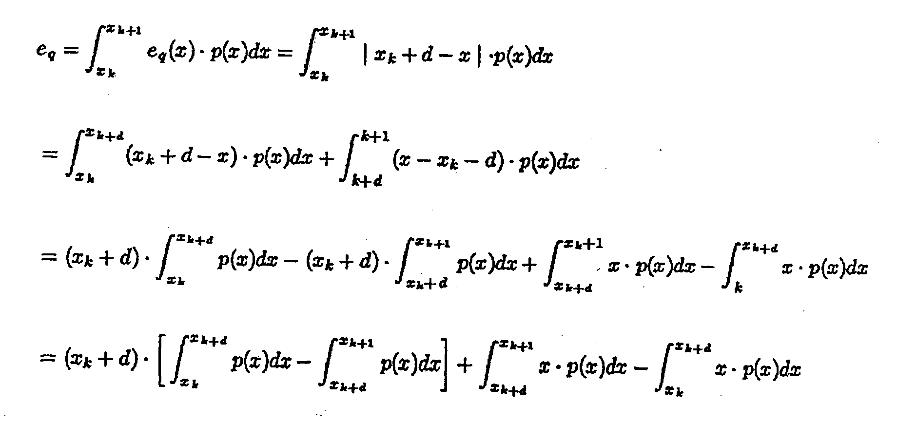
- In this way, the quantization error in each quantization ranges depends on the distance d of yk, from its left extremity xk. Because the goal is to minimize this error, the zeros of the first derivative have to be located as a function of d.
- In other words

- In the same way,

- It is now possible to calculate the derivative of the error with respect to d:

- Therefore, the point of minimum error corresponds with the median of the range.
- In the same way, it is possible to demonstrate that, starting from a range [Xk, Xk+1], the best subdivision in two different intervalsis the one that leads to equality of the two following functions in the two sub-ranges:


- From this, Iopt represents all the ranges with equal probability, univocally defined by L.
- "Quantization", in the video compression context, requires that each 16 bit coefficient (with sign) from the DCT transform of the prediction error is associated to a sub-set of discrete numbers, smaller than the original one, reducing, in this way, the spatial redundancy of the signal.
- Quantization of the DCT coefficients plays a key role in compression processes (this being true not just for the video context), since the final bitrate depends very strictly on this stage of the process. Specifically, the DCT transformation concentrates the energy associated to the input signal (e.g. the images of a video sequence) into small number of coefficients, which represent the lowest spatial frequencies. However the DCT transformation does not reduce the amount of data needed to represent the information. This means that, by applying a coarse quantization on these coefficients, a large number of zero coefficients can be removed from the high frequency region of each macroblock (where the human eye is less sensitive), thus achieving a true reduction of information.
- This is shown by way of example in figure 2, which represents an example of DCT coefficient quantization.
- This is the only one step that is not reversible in the compression chain (i.e. the relevant information is not transformed but at least partly lost).
- In the Intra-Coded macroblocks, briefly "Intra", belonging to the Intra-Coded frames ("I") or to the Predicted frames ("P" or "B") the DC component of each macroblock (the first coefficient in the upper left corner) and the AC components (all the other coefficients) are quantized separately, using the following rules:

 where C(u,v) are the quantized coefficients, F(u,v) are the DCT coefficients, Q(u,v) is the quantization step, QF is a quantization parameter and the sign is the sign of F(u,v).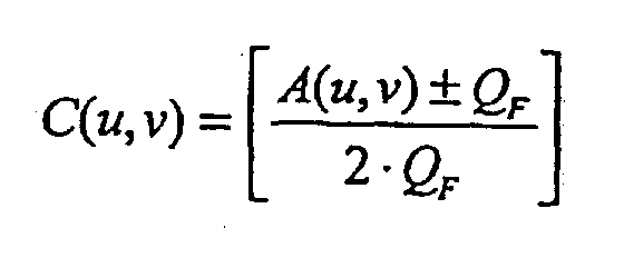
- The inverse quantization is obtained from the following rules:
- For those macroblocks which are predicted or interpolated, belonging thus to Predicted or Bidirectionslly Predicted frames (briefly "P" or "B" frames), the quantization process is the following:
 and the sign used is the sign of A(u,v).
The inverse quantization is obtained as follows: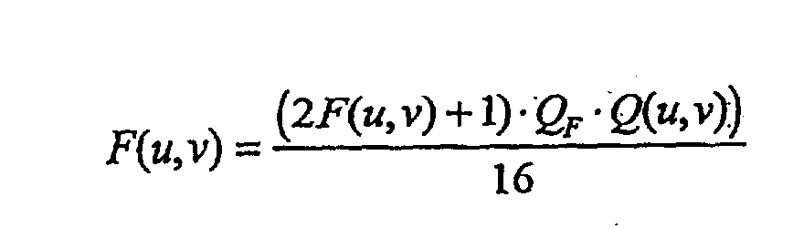
- The rate control algorithm calculates the QF parameter, which represents the real quantization level.
- To sum up, the quantization step is where the compression process becomes lossy, in the sense that the errors introduced are no longer recoverable. The total error depends on the spatial position of each coefficient in the block that contains it, and from the number of bits already spent from the beginning of the picture until the current macroblock (because the QF parameter can be changed for each macroblock).
- The minimum possible error is zero, when the quantizing coefficient is a multiple of the quantization step; the maximum possible error is equal to half the quantization step that contains the quantizing coefficient (referring to a non linear quantization scale). This means that if,quantization is too "hard" (the QF parameter having a high value) the resulting image will be appreciably degraded and the block artifacts visible. On the other hand, if the quantization is too "soft", the resulting images will be significantly more detailed, but a higher number of bits will be required to encode them.
- In the MPEG-2 standard, the DCT coefficients integer range of variability is [-2048, 2047]: the total number of quantization intervals L, depending on mQuant (the quantization level parameter, calculated by the rate control algorithm) is:
- For the Inter macroblocks, it is not generally possible to find a probability distribution of the coefficients (coding the prediction error). In fact, this depends on the input signal and the motion estimator characteristics. Recently, it has been demonstrated that it is possible to approximate a Laplacian distribution also for this kind of DCT coefficients, but the variability of its parameters are much bigger than for the Intra case. For this reason, a uniform distribution is currently assumed. The original coefficient is divided by the value mQuant, while moving toward the nearest integer.
- For the Intra macroblocks, the probability distribution of the DCT coefficients (excluding the DC coefficient) can be very well approximated by a Laplacian curve, centered on the zero value.
- Referring, by way of example, to the first 100 frames of the standard sequence known as Mobile & Calendar, the distribution of the corresponding AC-DCT coefficients may be well approximated by a Laplacian curve with parameter λ=0.055. The parameter λ can be very easily found, considering the Laplacian curve equation:
- Calculating experimentally the variance of the AC coefficients σ, the best Laplacian curve fitting the given points can be found as follow.


- Theoretically speaking, because a coefficient is sought to be quantized with quantization parameter mQuant, one must find all the 4096 / mQuantintervals with the same probability, and, for each one of them, the median value, the true goal being minimizing not the absolute quantization error, but rather its average value. Moreover, using for each interval the median value is important also for the subsequent VLC compression (shorter words will be associated with more frequent values): this increases the maximum quantization error. AS this is not a probable event, better compression with a minimized mean square error is allowed.
- For practical implementations, it is in any case preferable to simplify the quantizer, using again the one used for the Inter case. To do that, it is necessary to apply some modifications to the input coefficients, to adapt them to the different probability curve. In the Test Model Five (TM5), all the AC coefficient are pre-quantized using a matrix of fixed coefficients that eliminates all the frequency that are not perceptible; after that, adaptive quantization is applied, proportional to the parameter mQuant needed.
- Analyzing the function, each AC-DCT coefficient is quantized following this expression:

- This means that to each quantization interval (δ) will be associated a value which does not represent the mean value, but the mean value decremented by 1/8. This confirms that, since the probability distribution is not uniform in each interval (but can be approximated by a Laplacian curve) the most representative value of the interval itself is the median, which also minimizes the quantization error).
- As already indicated, MPEG2 standard defines syntax and semantics of the transmitted bitstream and the functionalities of the decoder. However, the encoder is not strictly standardized: any encoder that produces a valid MPEG2 bitstream is acceptable. The standard puts no constraints on important processing steps such as motion estimation, adaptive scalar quantization, and bit rate control.
- This last issue plays a fundamental role in actual systems working at Constant Bit Rate (briefly CBR). Due to the intrinsic structure of MPEG2, the final bitstream is produced at variable bit rate, hence it has to be transformed to constant bit rate by the insertion of an output buffer which acts as feedback controller. The buffer controller aims at achieving a target bit rate with consistent visual quality. It monitors the amount of bits produced at a macroblock-by-macroblock level and dynamically adjusts the quantization parameters for the subsequent ones, according to its fullness status and to the image complexity.
- Bit rate control is a central problem in designing moving pictures compression systems. It is essential to ensure that the number of bits used for a group of pictures (GOP) is as close as possible to a predetermined one. This is especially relevant in magnetic recording, and more in general, in those applications where strong constraints exist on instantaneous bitrate. In fact, in order to realize playback "trick" modes, such as "fast forward", it is necessary to start I-pictures at regularly spaced positions on the tape. In this kind of reproduction only the Intra pictures can be visualized: they allow a random access to the sequence since they are coded independently. Search is performed with a jump close to the GOP (Group Of Pictures) start code and then with a read step in the bitstream until the image starts. Hence, only the first image of the GOP is to be decoded.
- A constant bit rate per GOP is also an advantageous solution in the case of bitstream editing. It makes it possible to take a small part of the sequence, modify, re-encode and put it exactly where it was in the bitstream. Bit rate control algorithms based on pre-analysis can produce output bit rates that are very close to the desired one. They use information from a pre-analysis of the current picture, where such pre-analysis is a complete encoding of the image with a constant quantizer. Since the current picture is analyzed and then quantized, scene changes have no influence on the reliability of the pre-analysis.
- A procedure for controlling the bit-rate of the Test Model by adapting the macroblock quantization parameter is known as the Test Model 5 (TM5) rate control algorithm.
- The algorithm works in three steps:
- i) Target bit allocation: this step estimates the number of bits available to code the next picture. It is performed before coding the picture.
- ii) Rate control: this step sets by means of a "virtual buffer" the reference value of the quantization parameter for each macroblock.
- iii) Adaptive quantization: this step modulates the reference value of the quantization parameter according to the spatial activity in the macroblock to derive the value of the quantization parameter, mquant, which is used to quantize the macroblock.
-
- A first phase in the bit allocation step is complexity estimation. After a picture of a certain type (I, P, or B) is encoded, the respective "global complexity measure" (Xi, Xp, or Xb) is updated as:
- Xi = Si Qi, Xp = Sp Qp, Xb = Sb Qb where Si, Sp, Sb are the numbers of bits generated by encoding this picture and Qi, Qp and Qb are the average quantization parameter computed by averaging the actual quantization values used during the encoding of the all the macroblocks, including the skipped macroblocks.
-
- The initial values are:
- Xi=160*bit_rate/115
- Xp=60*bit_rate/115
- Xb=42*bit_rate/115 Where bit_rate is measured in bits/s.
-
- Subsequently, in the picture target-setting phase, the target number of bits for the next picture in the Group of Pictures (Ti, Tp, or Tb) is computed as:
- Kp and Kb are "universal" constants dependent on the quantization matrices; acceptable values for these are Kp = 1.0 and Kb = 1.4.
- R is the remaining number of bits assigned to the Group of Pictures. R is updated as follows.
-
- After encoding a picture, R = R - Si,p,b where is Si,p,b is the number of bits generated in the picture just encoded (picture type is I, P or B).
- Before encoding the first picture in a Group of Pictures (an I-picture):
N is the number of pictures in the Group of Pictures. - At the start of the sequence R = 0.
- Np and Nb are the number of P-pictures and B-pictures remaining in the current Group of Pictures in the encoding order.
- A subsequent step in the process is local control.
- Before encoding macroblock j (j>=1), the "fullness" of the appropriate virtual buffer is computed as:
- d0 i, d0 p, d0 b are initial fullnesses of virtual buffers - one for each picture type.
- Bj is the number of bits generated by encoding all macroblocks in the picture up to and including j.
- MB_cnt is the number of macroblocks in the picture.
- dj i, dj p, dj b are the fullnesses of virtual buffers at macroblock j - one for each picture type.
-
- The final fullness of the virtual buffer (dj i , dj p, dj b:j = MB_cnt) is used as d0 i, d0 p, d0 b for encoding the next picture of the same type.
- Next, compute the reference quantization parameter Qj for macroblock j as follows:
- The initial value for the virtual buffer fullness is:
- A third step in the process is adaptive quantization.
- A spatial activity measure for the marcroblock j is computed from the four luminance frame-organised sub-blocks and the four luminance field-organised sub-blocks using the infra (i.e. original) pixel values:where
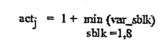 and Pk are the pixel values in the original 8*8 block. Normalized actj:
There mquantj is obtained as: - mquantj = Qj * N_actj where Qj is the reference quantization parameter obtained in step 2. The final value of mquantj is clipped to the range [1 ..31 ] and is used and coded as described in sections 7, 8 and 9 in either the slice or macroblock layer.
-
- This known arrangement has a number of drawbacks. First of all, step 1 does not handle scene changes efficiently.
- Also, a wrong value of avg_act is used in step 3 (adaptive quantization) after a scene change.
- Finally, VBV compliance is not guaranteed.
- Normally, the re-quantization process consists in a block of inverse quantization (IQ) followed by a quantization block (Q). It is mandatory to care about this operation, because the quantization errors can be very important, and they can get worse the images. Optimizations to this process are possible.
- When a uniform quantizer is used (as in TM5), it is possible to fuse together the two blocks in only one procedure, reducing both the computational costs and the errors related to this operation.
- Starting from the TM5 quantizer, above described, the Inter and Intra quantization error can be analyzed as follows.
- Considering a coefficient C, two quantization parameters A and B (with A<B) and the quantization CA and CB of C with respect to A and B.
- Designating CAB the re-quantization of CA and with respect to B:
- The re-quantized coefficient CAB must represent C with the minimum error possible, with respect to a direct quantization by the factor B. It has been demonstrated that this is true directly quantizing C respect to B, in other words obtaining the value CB.
- The re-quantization error is the difference between CAB and CB
- It is possible to demonstrate that:

- Therefore, the re-quantization error is bigger when the difference between the value A and B is smaller.
- The object of the invention is thus to provide alternative arrangements overcoming the drawback and limitations of the prior art arrangements considered in the foregoing.
- According to the present invention, this object is achieved by means of a method having the features set forth in the claims that follow. The invention also relates to a corresponding system as well as computer program product directly loadable in the memory of a digital computer and comprising software code portions for performing the method of the invention when the product is run on a computer.
- The invention will now be described, by way of example only, with reference to the annexed figures of drawing, wherein:
- figures 1 and 2, concerning the related art, were already described in the foregoing,
- figures 3 and 4, with figure 3 including two portions designed a) and b), respectively, shows a uniform quantization arrangement and the corresponding error,
- figure 5 shows an arrangement for uniform quantization using subtractive dithering,
- figure 6 shows an arrangement for uniform quantization using non-substractive dithering,
- figure 7 is a block diagram of a dithered re-quantizer,
- figure 8 is a block diagram of a downsampling transcoder,
- figure 9 is a three-dimensional diagram showing the relationship of output bitrate to input bitrate in an arrangement disclosed herein, and
- figure 10 shows a basic quality evaluation scheme for use in the context of the invention.
- Dithered quantization is a technique where a particular noisy signal, called dither, is summed to the input signal, before the quantization step, this step being usually carried out as a uniform quantization step.
- As described before, a uniform quantizer implements a correspondence between an analog signal (continuous) and a digital signal (discrete), formed by the collection of levels with the same probability.
- In the case of MPEG-2 signals, the input process can be considered as a stationary process Xn with n∈Z where Z represents the real numbers.
- As shown in figure 3a, the output of a quantizer block q fed with an input signal Xn is the process Xn=q(Xn). Figure 3b shows both the typical relationship of q(Xn) to Xn and the quantization error en.
- In a uniform quantizer, the hypothesis is that the quantization error is equal to en=q(Xn)-Xn. For this reason, the difference between input and output is a sequence of random variables, following a uniform distribution, uncorrelated between them and with the input.
- In this case, one can model the quantizer block q(X) as in figure 4 where en, is a sequence of uniform random variables, independent and all distributed in the same way,
- This approximation can be acceptable, inasmuch as the number N of quantization levels is high: this condition corresponds to a small quantization step Δ and the probability function of the input signal is, smoothed (Bennet approximation).
- Using a dithering signal as an input practically corresponds to forcing this condition even if not exactly met.
- Two different types of dithering are available: subtractive and non-subtractive.
- In the former case, as shown in figure 5, a random (or pseudo-random) noise signal is added to the input before quantization, Un=Xn + Wn, and is subtracted after the inverse quantization block, in order to reconstruct the input signal, removing the artifacts due to the non linear characteristic of the quantizer.
- When non-subtractive dithering is used as shown in figure 6, the input signal of the quantizer is the same, but no correction is applied to the inverse quantized signal.
- The introduction of such kind of error modifies the quantization error definition as follow:
- Therefore, the genera] difference between the original input and the final output (the quantization error) will be:
- Between the two types of dithering strategies, using the non-subtractive scheme is preferable for a number of reasons.
- First of all, even though having several advantages, subtractive dithering is difficult to implement in a real system, because the receiver needs to be very tightly synchronized with the transmitter, and this is not the case.
- Moreover, transmitting the generated random sequence together with the sequence also is hardly acceptable, as this will occupy a lot of space in the compressed stream, and this only to transmit noise.
- Secondly, subtractive dithering implies high arithmetic precision (so a large number of bits), but generally, integer variables are used.
- Several other factors need be considered when using a dithered approach for transcoding.
- A first factor is the target bitrate: data compression is obtained using an efficient VLC of the quantized DCT coefficients after the Run-Length coding. Analyzing re-quantization and the effects deriving from dithering, shows that applying this technique to all the DCT coefficients may not be advantageous.
- This is because in the high frequency part of the DCT coefficients matrix, several zero coefficients will modified to non-zero coefficients: this complicates the task of the subsequent VLC step, as these non-zero coefficients coefficients can no longer be compressed to one symbol as it would be the case for zero coefficients.
- For this reason, the output bit-rate will be higher: so, the rate controller will increase the quantization parameter mQuant, in order to follow the target bi-rate fixed, which would adversely affect the final image quality.
- The arrangement shown in figure 7 implies a double re-quantization cycle: for each coefficient considered, a value re-quantized with the normal procedure (i.e. without dither) is calculated.
- If the coefficient is zero, which is ascertained in a block downstream of the uniform quantizer q1, this will be directly fed to the final stream via a multiplexer module 102.
- Otherwise, for the non-zero coefficients - and only fo these, the re-quantized value is calculated again with the dithering procedure.
- Specifically, in the block diagram of figure 7 reference 104 indicates a summation mode (adder) where a dither signal is added to the AC-DCT signal upstream of another uniform quantizer q2, whose output is fed to the multiplexer 102.
- Quite obviously, the "parallel" arrangement shown in figure 7 that provides for the use of two quantizers q1 and q2 also lends itself to be implemented as a time-shared arrangement using a single quantizer only.
- The type of dither noise added before the quantization is significant. Its characteristics must be such as to uncorrelate the final quantization error from the input of the quantizer (the dithered original signal).
- Different types of noise may be used by adapting the characteristic function of the process that generates them: gaussian, uniform, sinusoidal and triangular.
- Any known procedure for pseudo-random variable generation with uniform distribution can be used to advantage in order to subsequently modify its distribution to obtain e.g. a gaussian or triangular distribution.
- In the case considered, a triangular distribution gives the best results, triangular noise being obtained as the sum of two independent, uniformly distributed pseudo-random variables.
- The ratio between the input and the output mQuant is to be taken into account, in that it is not always convenient to insert the noise signal before the linear quantization.
- From another point of view, when the input and the output mQuant are similar (equal or multiples), randomly correcting the coefficients may not be advantageous, so the dither is not applied in this condition.
- Different implementations of the output bitrate controller are thus possible for transcoding, with or without image size downsampling.
- The Constant Bit Rate (CBR) approach, rather that the Variable Bit Rate (VBR), is usually preferred: CBR is in fact representative of the real worst case, and, in general, a variable bit rate control algorithm can be intended as a constant one where the parameters are relaxed.
- The transcoding process is useful for decreasing the bit rate of a source data, in order, typically, to permit the contents to be conveyed over different channels with different available bandwidths, without giving rise to a long latency due to the receding process.
- A rate control algorithm can be derived from the TM5 approach and adapted by using e.g. the same level of local feedback (picture level) and the same global target bit calculation (GOP level).
- For the complexity calculation Xi, instead, the need exists of distinguishing between those bits needed for the so-called overhead (basically the headers, the motion vectors, etc.) and those bits allocated for the DCT coefficients, which are more correlated with the real image complexity.
- The incoming bit-stream is already quantized using the visibility matrices, and the chosen quantization parameter "mquant" carries the information of the local quality of each single macroblock. From this one can assume that the only one control variable is the quantization mquant:
- This decision is useful, in order to obtain a global control more stable.
- Having only one variable to be controlled, the dynamic range thereof is over a one-dimensional domain, where it is easier to work (also from the implementation point of view). Moreover, the macroblocks activity is not recalculated and, we rounding error due to the visibility matrices multiplications and divisions can be avoided. All the calculations are performed in fixed point, with a limited dynamic.
- To stabilize the system, a preanalysis block is added between the global control and the local one.
- A viable arrangement is a mixed feedback and feedforward approach.
- Upstream of the local control loop, a preanalysis routine is inserted, where each single picture is quantized (picture-preanalysis) with an hypothetic value of mquant (chosen experimentally after several simulations): at this point it is possible to count how many bits are spent in this condition, and take advantage from this information. The preanalysis result is called BUP (Bit Usage Profile) : the following final quantization routine can adjust the used mquant, basing its decisions on these values.
- Summarizing, preanalysis provides information to the local control routine: this is not only a complexity measure of each picture, but also an estimation between the number of bits spent for each DCT coefficient coding, and the bits spent for the overhead (header, motion vectors), that are a structural fixed payload, without changing the output standard.
- Locally, instead of a proportional control 8as this is the case of TM5), a proportional-integrative (PI)control described is used, e.g.:where e(t) is the instantaneous error function: e(t)=y0(t)-y(t). Kp is called the proportional action coefficient, T is the integration time (this must not be confused with the target bits) and then, the constant Ki is the ratio between Kp and Ti, called integral action constant.
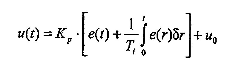
- The two constants Kp and Ki indicate the reactivity of the controller with respect to the proportional and integrative error. In this case, the only observable variable is the generated number of bits. An index proper does not exist that can measure the real quality of the coded images. So one may assume that y0(t) is a distribution of bits as follows:

- This type of control reduces the effect of a systematic error over the GOP under transcoding. For output bit rates higher than 4 Mbit/s, Ki and Kp can be assumed as constants. From the experiments, the mquant values very rarely approach the limit of the linear quantization "staircase".
- In the global control level, the target bits are assigned for each single picture of a GOP. In the implemented rate control the assumption is made, as in TM5, that image complexity can be correlated with its predecessor of the same type I, P or B.
- The calculation of the complexity and the targets is performed differently from TM5. The assumption is made that in current GOP there are R available bits and k pictures already coded so that:where R1 are the remaining bits (left) to be used to encode the following N-k pictures. If T[n] is the target for the picture n of the GOP, then:
 and then: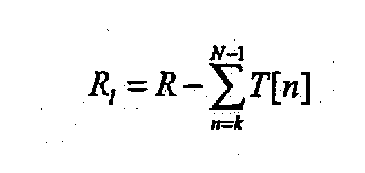
- For any picture type (i), the target bits are the sum of the bits spent for the overhead (Oi) and the bits spent for the DCT coefficients (Ci) :
- With these definitions, the image complexity Xi can be calculated as follows:
- The proportional constants KIP and KIB can be determined as follows:
- The expressions for the target bit, used for the global control level are then derived, obtaining:
- Even if the MPEG-2 standard (Main profile @ Main level at standard TV resolution) allows transmissions with data rate up to 15 Mbit/s, the real low limit of its applicability range (in order to obtain always good image quality) is about 4 Mbit/sec: below that limit, the visual quality is not good enough, and different processing techniques need be applied.
- One possibility is to reduce the frame rate simply skipping some frames; another, more complex approach that also preserves more "global" sequence quality, is to downsize each image, reducing its dimension to 1/2 or 1/4.
- An arrangement applying that principle is shown in figure 8, where references IS and OS indicate the video input and output sequences, respectively.
- Reference 200 designates the sequence GOP header that feeds a sequence GOP data delay memory 202, that in turn feeds an output multiplexer 204.
- The header 200 also feeds a picture header 206 that, via a multiplexer 208, feeds a local cache memory 210 adapted to cooperate with the multiplexer 204 as well as still another multiplexer 212.
- The multiplexer 212 receives input signals from the multiplexer 208 and the memory 210 and feeds them to a processing chain including a cascaded arrangement of:
- an inverse VLC (I-VLC) block 214,
- an inverse RL (I-RL) block 216,
- a low-pass filter 218,
- a 1:2 downsampler block 220,
- an inverse quantizer 222 followed by a quantizer 224,
- a RL coding block 226,
- a VLC coding block 228, and
- a multiplexer 230 arranged to alternatively send the signal from the VLC block 228 to the output multiplexer 204 or a picture preanalysis chain comprised of a bit profile usage module 232 and a rate control (Mquant) module 234 which in turn controls the quantizer 224 by adjusting the quantization step used therein.
- To sum up, the system shown in figure 8 includes two additional blocks (that can be incorporated to one): the low pass filter 218 and the downsampler 220.
- Even if the syntax is the same, the output bitstream OS will no longer be strictly MPEG-2 compliant, because macroblocks are encoded over 8 pixel width and height while MPEG-2 only allows 16 pixels as the macroblock dimensions.
- So a specific decoder working on low-resolution anchor frames may be required. Alternatively, by changing slightly the syntax of the headers and the output VLC block, an H.26L compliant bit-stream can be produced.
- H.26L is an emerging standard, expected to be largely used in the near future and probably to substitute the MPEG-4 standard in wireless communications, also known as H.264.
- An advantage of this technique is that the decoding process is performed on low-resolution images, largely reducing the blocking artifacts. These considerations are also confirmed by measuring the block artifact level factor with the GBIM technique (see "A generalized block-edge impairment metric for video coding", H.R. Wu and M.Yuen, IEEE Signal Processing Letters, vol. 4, No. 11, November 1997).
- At least two different implementations of the system can be envisaged.
- In a first embodiment, low pass filtering is performed before preanalysis: in this case the block dimensions will remain 8x8 pixels, but only the low frequency portion (4x4 pixels) will be not-zero. In this case, the result is sub-optimal, but the advantage is that the output bit-stream will still be MPEG-2 compliant.
- Alternatively, together with the low-pass filtering, a decimation phase is executed: the blocks will be 4x4 pixels large, and the subsequent RL and VLC coding steps will be effected on this structure, generating a non MPEG-2 bitstream. With this approach a better quality can be reached.
- The MPEG-2 video standard exhibits some limitations for low bit-rates: the most evident one is that the hierarchy syntax is very rigid and cannot be changed, according to what is really written into the bit-stream.
- The transcoder does not execute a complete recoding of the bit-stream content, but reduces the information carried by the DCT coefficients with a stronger quantization. This implies that all the semantic structures of the incoming bit-stream (headers, motion vectors, but also the macroblocks number) are not changed and the bits used for this part of the stream will be more or less copied into the output one (syntax overhead).
- For this reason, for very low bit-rates (under 1.5 Mbit for a Dl incoming image format and CIF as output), it is not fair to compare this approach versus a complete decoding-filtering-reencoding process, because in this last case, 1/4 of the incoming macroblocks will be encoded, reducing by roughly a factor 4 the named overhead.
- In any case, this second approach requires, in addition to a complete decoding of the incoming stream, a new motion estimation and a bigger latency with the output: this latter limitation could be quite significant e.g. in video-conferencing applications, where interactivity of the speakers (two or more) must be very strict.
- Moreover, under these conditions, the possible dynamics of the mquant variations are reduced, because the quantization parameters used are close to their upper limit. For that reason, any large variation with respect to the average mquant will be very visible, and the controller will must take in account also this problem.
- Also, the rate control implementation can be different, according to the application and the data bandwidth available on the transmission (or storage) channel. For a CBR channel with low capacity (less than 1.5 Mbit/second) and low latency a very precise rate control is important, accepting some block artifacts.
- The situation is different if the only constraint is the final dimension of the data stream (consider an HDD or a magnetic support): in this case, a smaller local precision can be tolerated.
- In the preferred implementation of the transcoding system, two different variations of the rate control are provided for low bitrate applications and only one for high bitrate.
- The difference between the two types of rate control for low bit rate applications lies in how the local feedback is taken in account and in the preanalysis step.
- The two controllers can be termed "High" and "Low" feed-back: in both instances, the basic structure is comprised of global control (for the target calculation), preanalysis and a local feed-back loop, and the parameters depend from the input and output bitrates.
- In the cases of a low bitrate, in the target bit rate calculation, a proportional control parameter is needed (Kp): this constant can be parametrized, depending on the input/output bit rate as follows:
- This is shown in figure 14, where the value of K-Prop (Kp) is shown as a function of the input bitrate and the output bitrate. In order to enhance the precision of the preanalysis (in terms of mquant calculated) the mquant used to find the BUP (Bit Usage Profile) must also be made parametrical.
- In particular, if for high bitrates a fixed value V can be used, for low bit rates an offset is added to this value. Such an offset depends again from the difference between the input and the output bitrate.
- At the end of the preanalysis, two different working conditions are present concerning the BUP.
- The former one is verified when we are in the condition of "high feedback", the BUP is calculated as explained before. When a low feedback is chosen, a new contribution is needed as the derivative.
- If, the mquant value is calculated "proportionally", a correction must be done as follow:
- In a preferred embodiment, as derivative estimation, the difference between the re-quantization mquant value of the current macroblock and the average of the previous picture has been chosen.
- The derivative contribution is introduced, in order to delay possible abrupt variation in the local control, and render the control more stable.
- The value of the constant KD is then negative, and it depends again on the input and output bit rates:
- The proportional constant in the local control, that is proportional and integrative when the control is tight, is very low (down to 0): only the integrative contribution remains important. This fact allows a very precise control of the final dimension of each GOP, and the absence of proportional control prevents eventually fast variation of the mquant.
- The arrangement disclosed herein has been evaluated in terms of quality by referring to the scheme shown in figure 10, where source samples SS are fed into an MPEG-2 encoder ENCMP2.
- The coded data bitstream, at a bitrate B1 was fed in parallel to:
- a decoding/re-encoding chain including an MPEG-2 decoder DECMP2 followed by another MPEG-2 encoder ENCMP2' to re-encode the samples at a lower bitrate B2 in view of feeding to a further MPEG-2 decoder DECMP2', and
- a downsampling transcoder DRS essentially corresponding to the diagram of figure 9, configured to transcode the video signal at the bitrate B2 followed by another MPEG-2 decoder DECMP2''.
- The goal of these measures is to ascertain whether the final quality is increased as a result of dithering being added to the quantization block of re-quantization.
- The sequences used exhibit different characteristics, as number of details per frame (Mobile&Calendar), or global movements like panning (FlowerGarden), etc.
- Two different criteria have been used for the quality evaluation.
- The former is objective quality measurement, through the PSNR (Peak Signal Noise Ratio) index.
- The latter is subjective quality evaluation, watching the sequences via professional equipment (an image sequence processor called 'Digitale VideoSysteme' and a 'Barco' CVM3051 monitor).
- The PSNR measures reported in Table 1 confirm the enhancement of the quality using the dithered re-quantization.
- In the table below, the results obtained transcoding from 7 Mbit/s to 3/2/1.5 Mbit/sec are presented. These numbers are compared with the rate control with high (local proportional-integrative) and low (preanalisys proportional-derivative and local integrative) feedback. The sequence is the Philips one, 725 progressive PAL frames, 25 frame/sec, Dl resolution (720x576) down to CIF (360x288).
High and Low feed-back comparisons: file size in bytes with KIP and KIP=1.0 BitRate Target Low feed-back % Err. High feed-back % Err. 1.5Mbit/s 5437500 5310112 -2.34 5255598 -2.9 2.0Mbit/s 7250000 7114829 -1.86 7124522 -1.73 3.0Mbit/s 10875000 1068468750 -1.75 10687411 -1.72 - It is also evident that the quality gain depends from the final target bitrate and from the sequence content: the gain becomes important when dithering can work well. In other words, when the original sequence is full of details and movements, the gain will be higher: in any case, the final images are never damaged, and in the worst case, the gain will is null.
- It is also important to underline that the quality gain is interesting (about 1 dB) in the middle range of quality (i.e. between 25 and 35 dB) where it is more visible; for higher quality (from 40 to 45 dB) the gain is less, but also its visibility cannot be high, because the starting quality is already very high.
- Other tests have been performed on a different Dl progressive sequence, transcoding with downsampling to 2 and 1.5Mbit/s.
- For each sequence used, the main characteristics were as follows:
- 1. Demoiselle: PAL D 1, 720x576x25 f/s, 1000 frames;
- 2. Titan: PAL Dl, 720x576x25 f/s, 930 frames;
- 3. Philips: PAL Dl, 720x576x25 f/s, 700 frames;
- 4. Twister: PAL D1, 720x576x25 f/s, 1000 frames.
-
- The results are summarized in Table 2 below.
Low feedback rate control File size in bytes, KIP=1.0, KPB=1.0 Sequence Target 2Mbit/s File size &Err. Target 1.5 Mbit/s File Size &Err. Demoiselle 10000000 9862370 -1.38 7500000 7211351 -3.80 Titan 9320000 9191424 -1.38 7110000 6932480 -2.50 Philip 7080000 6867596 -2.80 5310000 8217141 -1.75 Twister 10000000 9818110 -1.80 7500000 7199840 -4.0 
- As regarding the simulation results in terms of PSNR (Peak Signal to Noise Ratio), several transcoding bitrates have been tested: in particular from 10 to 4, from 7 to 4 and from 4 to 4 Mbit/second.
- This latest case is useful to check if the dither signal can adversely affect the transcoding process, when the characteristic curves of input and output are the same. In any case, the fact must be taken into account that this case cannot exist in the real system because under these circumstances the transcoder will simply forward the input bitstream IS to the output OS, without any processing.
- Additional results are provided in Table 3 below.
Mean PSNR (dB) (Dithered vs. Standard Re-quantization) 7 to 4 Mbits 10 to 4 Mbit/sec 4 to 4 Mbit/sec Y U V Y U V Y U V Mobile&Calendar 0.83 0.77 0.75 1.05 0.86 0.82 0.06 0.00 0.00 Flower Garden 0.92 0.32 0.36 0.93 0.39 0.50 0.19 0.05 0.07 Brazilg 0.40 0.02 0.10 0.10 0.01 -0.09 0.00 -0.02 -0.01 Stefan 0.68 0.46 0.55 0.59 0.48 0.55 0.00 -0.01 -0.02 Fball 0.18 0.08 0.06 0.02 0.00 0.00 0.00 0.00 0.01 - Table 1 shows that the luminance component is never damaged (positive numbers means a gain of the dithered approach with respect to the traditional one).
- Concerning the chrominance components (U and V) in some special conditions (e.g. when the sequence is not rich of details) very small degradation may occur: this is not visible and does not change the general behaviour of the system.
- In the worst case (transcoding to the same output bitrate as the input one) there are not evident losses of quality: so using the dithering also in this condition does not introduce loss of quality, with respect to standard re-quantization. In very smoothed and uniform sequences, like Brazilg) or sequences exhibiting frequent scene cuts and movements changes (like Fball), the gain is smaller than in the other cases. For very detailed sequences like Mobile&Calendar, instead, the average gain can reach up to 1 dB.
- Analysis of scattergrams for luminance and chrominance are shows that the dithered approach is better in the range of quality between 25 and 35 dB, where the advantageous effects are clearly detectable.
- Essentially, the arrangement disclosed herein enhances the quality achievable in a system for transcoding multimedia streams without introducing complexity. Re-quantization is very easy to implement, and lead to better final quality, without any drawback.
- A gain in quality is thus achieved, without introducing complexity in the systems. This is a significant point as video transcoding techniques are becoming more and more important for a broad range of applications in the consumer electronics field: this particular approach can be easily applied, enhancing performance of the transcoding system.
- Of course, the underlying principle of the invention remaining the same, the details and embodiments may vary, also significantly, with respect to what has been described and shown by way of example only, without departing from the scope of the invention as defined by the annexed claims.
Claims (32)
- A method of converting digital signals between a first (IS) and second (OS) format, the method including the step of generating coefficients (Xn) representative of such digital signals and the step of subjecting such coefficients to quantization (q), characterized in that it includes the steps of:generating a dither signal (Wn), andadding said dither signal (Wn) to said coefficients (Xn) before said quantization (q) to generate a quantized signal.
- The method of claim 1, characterized in that it said quantization step is a uniform quantization step (q).
- The method of claims 1 or 2, characterized in that it includes the steps of:subjecting such quantized signal to inverse quantization, andsubtracting said dither signal (Wn) from said signal subjected to inverse quantization.
- The method of any of the previous claims, characterized in that it includes the steps of:subjecting each said coefficient (Xn) to a first quantization step (q1) in the absence of any said dither signal (Wn) being added to generate an undithered quantized coefficient,checking if said undithered quantized coefficient is equal to zero, andwhen said undithered quantized coefficient is equal to zero, taking said undithered quantization coefficient as said quantized signal, andwhen said undithered quantized coefficient is different from zero, adding said dither signal (Wn) to said coefficient (Xn) and subjecting said dithered coefficient to a quantization step (q2) to generate said quantized signal.
- The method of any of the previous claims, characterized in that the spectrum of said dither signal (W) is selected from the group consisting of : gaussian, uniform, sinusoidal and triangular.
- The method of claim 5, characterized in that said dither signal (Wn) is generated as a pseudo-random variable having a uniform distribution by subsequently modifying said distribution to at least one distribution of said group.
- The method of any of claims 1, 5 or 6, characterized in that said dither signal is generated from a plurality of independent pseudo-random variables.
- The method of any of the previous claims, characterized in that it includes the step of subjecting said digital signals to a discrete cosine transform (DCT) to generate said coefficients to be quantized as DCT coefficients.
- The method of any of the previous claims, characterized in that said quantization is a part of a transcoding process between an input stream (IS) of digital signals at a first bitrate (B1) and an output stream of digital signals (OS) at a second bitrate (B2), said second bitrate (B2) of said output stream (OS) of digital signals being selectively controlled.
- The method of claim 9, characterized in that said input stream (IS) is subject to a preanalysis process (232, 234) including:quantizing said signals with a given quantization step (mquant), andevaluating the number of bits spent for coding said coefficients, and in that said bitrate (B2) of said output data stream (OS) is controlled as a function of said preanalysis.
- The method of claim 10, characterized in that said control is of a proportional-integrative (PI) type.
- The method of either of claims 10 or 11, characterized in that said input stream (IS) is stream of digital video signals including pictures arranged in groups of pictures (GOP), and in that said bitrate control assign value of target bits for each single picture of a group of pictures (GOP).
- The method of any of the previous claims, characterized in that said quantization step (2 to 4) is a part of a transcoding process between an input stream of digital signals (IS) at a first bitrate (B1) and an output bitrate (OS) at a second bitrate (B2), said transcoding process including subjecting at least part of said input digital signals to a low pass filtering step (218) followed by a downsampling step (220).
- The method of claim 10 and claim 13, characterized in that said low pass filtering (218) is performed before said preanalysis.
- The method of claim 13, characterized in that together with said low-pass filtering (218) a decimation step is executed.
- The method of any of the previous claims, characterized in that said digital signals are, in at least one of said first and second formats, MPEG encoded signals.
- A system for converting digital signals between a first (IS) and second (OS) format, the system being configured (18) for generating coefficients (Xn) representative of such digital signals and including at least one quantizer (20; q; q1; q2) for subjecting such coefficients to quantization, characterized in that it includes:a source of a dither signal (Wn), andan adder for adding said dither signal (Wn) to said coefficients (Xn) before said quantization (q) to generate a quantized signal.
- The system of claim 17 characterized in that it said quantizer (20; q; q1; q2) is a uniform quantizer (q).
- The system of either of claims 17 or 18, characterized in that it includes:an inverse quantizer for subjecting such quantized signal to inverse quantization, anda subtractor for subtracting said dither signal (Wn) from said signal subjected to inverse quantization.
- The system of any of the previous claims 17 to 19, characterized in that it includes:a first quantizer (q1) for subjecting each said coefficient (Xn) to a first quantization step in the absence of any said dither signal (Wn) being added to generate an undithered quantized coefficient,a control module (100) for checking if said undithered quantized coefficient is equal to zero,an output element (102) for taking said undithered quantization coefficient as said quantized signal when said undithered quantized coefficient is equal to zero, andan adder (104) for adding said dither signal (Wn) to said coefficient (Xn) when said undithered quantized coefficient is different from zero, and a second quantizer (q2) for subjecting said dithered coefficient to a quantization step to generate said quantized signal for feeding to said output element (102) .
- The system of any of the previous claims 17 to 20, characterized in that said source of said dither signal (W) is a source of signal having a distribution selected from the group consisting of: gaussian, uniform, sinusoidal and triangular.
- The system of claim 21, characterized in that said source is a source of a pseudo-random variable having a uniform distribution having associated a distribution modifier element for modifying said distribution to at least one distribution of said group.
- The system of any of claims 17, 21 or 22, characterized in that said source of dither signal includes a plurality of sources of independent pseudo-random variables.
- The system of any of the previous claims, characterized in that it includes a DCT transform module (18) for subjecting said digital signals to a discrete cosine transform (DCT) to generate said coefficients to be quantized as DCT coefficients.
- The system of any of the previous claims 17 to 24, as a part of a transcoder for transcoding an input stream (IS) of digital signals at a first bitrate (B1) into an output stream (OS) of digital signals at a second bitrate (B2), including a bitrate control block (234) for selectively controlling said second bitrate (B2) of said output stream (OS) of digital signals.
- The system of claim 25, characterized in that it includes a preanalysis chain (224, 232, 234) for subjecting said input stream (IS) to a preanalysis process (232, 234), said chain including:a quantizer (224) for quantizing said signals with a given quantization step (mquant), anda bit usage profile module (232) for evaluating the number of bits spent for coding said coefficients,and in that said bitrate control block (234) is configured for controlling the bitrate (B2) of said output data stream (OS) as a function of said preanalysis.
- The system of claim 26, characterized in that said bitrate control block (234) includes a proportional-integrative (PI) controller.
- The system of either of claims 26 or 27, for use in connection with an input stream (IS) of digital video signals including pictures arranged in groups of pictures (GOP), characterized in that said bitrate control block (234) is configured for assigning said value of target bits for each single picture of a group of pictures (GOP).
- The system of any of the previous claims, characterized in that said quantizer (224) is a part of a transcoder adapted for transcoding an input stream of digital signals (IS) at a first bitrate (B1) into an output bitrate (OS) at a second bitrate (B2), said transcoder including a low pass filter (218) followed by a downsampling module (220) for subjecting at least part of said input digital signals to lowpass filtering and downsampling
- The method of claim 26 and claim 29, characterized in that said low pass filter (218) is arranged upstream of said preanalysis chain (224, 232, 234).
- The system of claim 29, characterized in that a decimation module is associated with said low-pass filter (218).
- A computer program product directly loadable in the internal memory of a digital computer and including software code portions for performing the method of any of claims 1 to 16 when the product is run on a computer.
Priority Applications (2)
| Application Number | Priority Date | Filing Date | Title |
|---|---|---|---|
| EP03002443A EP1445958A1 (en) | 2003-02-05 | 2003-02-05 | Quantization method and system, for instance for video MPEG applications, and computer program product therefor |
| US10/757,961 US7301999B2 (en) | 2003-02-05 | 2004-01-14 | Quantization method and system for video MPEG applications and computer program product therefor |
Applications Claiming Priority (1)
| Application Number | Priority Date | Filing Date | Title |
|---|---|---|---|
| EP03002443A EP1445958A1 (en) | 2003-02-05 | 2003-02-05 | Quantization method and system, for instance for video MPEG applications, and computer program product therefor |
Publications (1)
| Publication Number | Publication Date |
|---|---|
| EP1445958A1 true EP1445958A1 (en) | 2004-08-11 |
Family
ID=32605325
Family Applications (1)
| Application Number | Title | Priority Date | Filing Date |
|---|---|---|---|
| EP03002443A Withdrawn EP1445958A1 (en) | 2003-02-05 | 2003-02-05 | Quantization method and system, for instance for video MPEG applications, and computer program product therefor |
Country Status (2)
| Country | Link |
|---|---|
| US (1) | US7301999B2 (en) |
| EP (1) | EP1445958A1 (en) |
Cited By (9)
| Publication number | Priority date | Publication date | Assignee | Title |
|---|---|---|---|---|
| WO2008060262A1 (en) * | 2005-09-07 | 2008-05-22 | Vidyo, Inc. | System and method for scalable and low-delay videoconferencing using scalable video coding |
| CN101924889A (en) * | 2009-06-11 | 2010-12-22 | 索尼公司 | Image processing apparatus, image processing method, and program |
| CN101924890A (en) * | 2009-06-11 | 2010-12-22 | 索尼公司 | Image processing device and image processing method |
| CN101507267B (en) * | 2005-09-07 | 2011-09-14 | 维德约股份有限公司 | System and method for scalable and low-delay videoconferencing using scalable video coding |
| US8289370B2 (en) | 2005-07-20 | 2012-10-16 | Vidyo, Inc. | System and method for scalable and low-delay videoconferencing using scalable video coding |
| US8699522B2 (en) | 2005-07-20 | 2014-04-15 | Vidyo, Inc. | System and method for low delay, interactive communication using multiple TCP connections and scalable coding |
| CN104125460A (en) * | 2013-04-26 | 2014-10-29 | 韩国科亚电子股份有限公司 | Method and apparatus for controlling video bitrates |
| US8938004B2 (en) | 2011-03-10 | 2015-01-20 | Vidyo, Inc. | Dependency parameter set for scalable video coding |
| US9313486B2 (en) | 2012-06-20 | 2016-04-12 | Vidyo, Inc. | Hybrid video coding techniques |
Families Citing this family (48)
| Publication number | Priority date | Publication date | Assignee | Title |
|---|---|---|---|---|
| DE10346157A1 (en) * | 2003-10-04 | 2005-05-12 | Basf Coatings Ag | Liquid rheology aids, process for their preparation and their use |
| US7746927B1 (en) * | 2004-03-26 | 2010-06-29 | Apple Inc. | Robust single-pass variable bit rate encoding |
| US7593465B2 (en) * | 2004-09-27 | 2009-09-22 | Lsi Corporation | Method for video coding artifacts concealment |
| CA2582531C (en) * | 2004-10-18 | 2013-03-12 | Nippon Telegraph And Telephone Corporation | Video quality objective evaluation device, evaluation method, and program |
| US7574059B2 (en) * | 2004-10-29 | 2009-08-11 | Broadcom Corporation | System, method, and apparatus for providing massively scaled down video using iconification |
| US7751478B2 (en) * | 2005-01-21 | 2010-07-06 | Seiko Epson Corporation | Prediction intra-mode selection in an encoder |
| US8031774B2 (en) * | 2005-01-31 | 2011-10-04 | Mediatek Incoropration | Video encoding methods and systems with frame-layer rate control |
| US8422546B2 (en) * | 2005-05-25 | 2013-04-16 | Microsoft Corporation | Adaptive video encoding using a perceptual model |
| US7830961B2 (en) * | 2005-06-21 | 2010-11-09 | Seiko Epson Corporation | Motion estimation and inter-mode prediction |
| US7778476B2 (en) * | 2005-10-21 | 2010-08-17 | Maxim Integrated Products, Inc. | System and method for transform coding randomization |
| US7843995B2 (en) * | 2005-12-19 | 2010-11-30 | Seiko Epson Corporation | Temporal and spatial analysis of a video macroblock |
| US8170102B2 (en) * | 2005-12-19 | 2012-05-01 | Seiko Epson Corporation | Macroblock homogeneity analysis and inter mode prediction |
| US8059721B2 (en) | 2006-04-07 | 2011-11-15 | Microsoft Corporation | Estimating sample-domain distortion in the transform domain with rounding compensation |
| US7995649B2 (en) | 2006-04-07 | 2011-08-09 | Microsoft Corporation | Quantization adjustment based on texture level |
| US8130828B2 (en) | 2006-04-07 | 2012-03-06 | Microsoft Corporation | Adjusting quantization to preserve non-zero AC coefficients |
| US7974340B2 (en) * | 2006-04-07 | 2011-07-05 | Microsoft Corporation | Adaptive B-picture quantization control |
| US8503536B2 (en) | 2006-04-07 | 2013-08-06 | Microsoft Corporation | Quantization adjustments for DC shift artifacts |
| US8711925B2 (en) | 2006-05-05 | 2014-04-29 | Microsoft Corporation | Flexible quantization |
| US8238424B2 (en) | 2007-02-09 | 2012-08-07 | Microsoft Corporation | Complexity-based adaptive preprocessing for multiple-pass video compression |
| US8396118B2 (en) * | 2007-03-19 | 2013-03-12 | Sony Corporation | System and method to control compressed video picture quality for a given average bit rate |
| US8498335B2 (en) | 2007-03-26 | 2013-07-30 | Microsoft Corporation | Adaptive deadzone size adjustment in quantization |
| US8243797B2 (en) | 2007-03-30 | 2012-08-14 | Microsoft Corporation | Regions of interest for quality adjustments |
| US8442337B2 (en) | 2007-04-18 | 2013-05-14 | Microsoft Corporation | Encoding adjustments for animation content |
| CN101079635B (en) * | 2007-05-24 | 2011-10-05 | 北京邮电大学 | Joint scalar quantity quantification method and level quantification method of self-adapted scalar quantity adjustment |
| US8331438B2 (en) | 2007-06-05 | 2012-12-11 | Microsoft Corporation | Adaptive selection of picture-level quantization parameters for predicted video pictures |
| WO2009032255A2 (en) * | 2007-09-04 | 2009-03-12 | The Regents Of The University Of California | Hierarchical motion vector processing method, software and devices |
| US8750390B2 (en) | 2008-01-10 | 2014-06-10 | Microsoft Corporation | Filtering and dithering as pre-processing before encoding |
| US20090201380A1 (en) * | 2008-02-12 | 2009-08-13 | Decisive Analytics Corporation | Method and apparatus for streamlined wireless data transfer |
| US8160132B2 (en) | 2008-02-15 | 2012-04-17 | Microsoft Corporation | Reducing key picture popping effects in video |
| US8189933B2 (en) | 2008-03-31 | 2012-05-29 | Microsoft Corporation | Classifying and controlling encoding quality for textured, dark smooth and smooth video content |
| US8897359B2 (en) | 2008-06-03 | 2014-11-25 | Microsoft Corporation | Adaptive quantization for enhancement layer video coding |
| US7688245B2 (en) * | 2008-07-11 | 2010-03-30 | Infineon Technologies Ag | Method for quantizing of signal values and quantizer |
| US9571856B2 (en) | 2008-08-25 | 2017-02-14 | Microsoft Technology Licensing, Llc | Conversion operations in scalable video encoding and decoding |
| US8805106B2 (en) * | 2008-09-26 | 2014-08-12 | Futurewei Technologies, Inc. | System and method for compressing and decompressing images and video |
| US20100235314A1 (en) * | 2009-02-12 | 2010-09-16 | Decisive Analytics Corporation | Method and apparatus for analyzing and interrelating video data |
| US8458105B2 (en) * | 2009-02-12 | 2013-06-04 | Decisive Analytics Corporation | Method and apparatus for analyzing and interrelating data |
| US8654838B2 (en) | 2009-08-31 | 2014-02-18 | Nxp B.V. | System and method for video and graphic compression using multiple different compression techniques and compression error feedback |
| GB2475878A (en) * | 2009-12-03 | 2011-06-08 | St Microelectronics | Obtaining dithered image data word by adding noise contribution |
| US9819358B2 (en) * | 2010-02-19 | 2017-11-14 | Skype | Entropy encoding based on observed frequency |
| US9078009B2 (en) * | 2010-02-19 | 2015-07-07 | Skype | Data compression for video utilizing non-translational motion information |
| US20110206132A1 (en) * | 2010-02-19 | 2011-08-25 | Lazar Bivolarsky | Data Compression for Video |
| US9313526B2 (en) * | 2010-02-19 | 2016-04-12 | Skype | Data compression for video |
| US9609342B2 (en) * | 2010-02-19 | 2017-03-28 | Skype | Compression for frames of a video signal using selected candidate blocks |
| US20120275502A1 (en) * | 2011-04-26 | 2012-11-01 | Fang-Yi Hsieh | Apparatus for dynamically adjusting video decoding complexity, and associated method |
| US8477053B2 (en) * | 2011-06-06 | 2013-07-02 | Analog Devices, Inc. | ADC with resolution detector and variable dither |
| US9307235B2 (en) * | 2012-12-03 | 2016-04-05 | Vixs Systems, Inc. | Video encoding system with adaptive hierarchical B-frames and method for use therewith |
| US9955163B2 (en) | 2013-06-17 | 2018-04-24 | Google Llc | Two pass quantization of video data |
| US9363421B1 (en) | 2015-01-12 | 2016-06-07 | Google Inc. | Correcting for artifacts in an encoder and decoder |
Citations (2)
| Publication number | Priority date | Publication date | Assignee | Title |
|---|---|---|---|---|
| EP0509576A2 (en) * | 1991-04-18 | 1992-10-21 | Ampex Systems Corporation | Method and apparatus for determining a quantizing factor for processes involving multiple compression/decompression of data |
| WO2001095633A2 (en) * | 2000-06-09 | 2001-12-13 | General Instrument Corporation | Video size conversion and transcoding from mpeg-2 to mpeg-4 |
Family Cites Families (11)
| Publication number | Priority date | Publication date | Assignee | Title |
|---|---|---|---|---|
| US5225904A (en) * | 1987-10-05 | 1993-07-06 | Intel Corporation | Adaptive digital video compression system |
| US5887115A (en) * | 1993-01-13 | 1999-03-23 | Hitachi America, Ltd. | Method and apparatus for implementing a video tape recorder for recording digital video signals having either a fixed or variable data transmission rate |
| US6614914B1 (en) * | 1995-05-08 | 2003-09-02 | Digimarc Corporation | Watermark embedder and reader |
| US5920354A (en) * | 1998-01-13 | 1999-07-06 | Thomson Consumer Electronics | HDTV to NTSC transcoder system |
| US6466623B1 (en) * | 1998-03-27 | 2002-10-15 | Industrial Technology Research Institute | Method and apparatus for motion estimation for high performance transcoding |
| US6798420B1 (en) * | 1998-11-09 | 2004-09-28 | Broadcom Corporation | Video and graphics system with a single-port RAM |
| US6879652B1 (en) * | 2000-07-14 | 2005-04-12 | Nielsen Media Research, Inc. | Method for encoding an input signal |
| US6944226B1 (en) * | 2000-10-03 | 2005-09-13 | Matsushita Electric Corporation Of America | System and associated method for transcoding discrete cosine transform coded signals |
| CN1223197C (en) * | 2000-10-10 | 2005-10-12 | 皇家菲利浦电子有限公司 | Video bit rate control method and device for digital video recording |
| US7024172B1 (en) * | 2001-06-15 | 2006-04-04 | Rockwell Collins, Inc. | Direct conversion receiver using a dithered local oscillator to mitigate adjacent channel coherent interference |
| US6628300B2 (en) * | 2001-11-30 | 2003-09-30 | International Business Machines Corporation | Transcoding proxy and method for transcoding encoded streams |
-
2003
- 2003-02-05 EP EP03002443A patent/EP1445958A1/en not_active Withdrawn
-
2004
- 2004-01-14 US US10/757,961 patent/US7301999B2/en not_active Expired - Lifetime
Patent Citations (2)
| Publication number | Priority date | Publication date | Assignee | Title |
|---|---|---|---|---|
| EP0509576A2 (en) * | 1991-04-18 | 1992-10-21 | Ampex Systems Corporation | Method and apparatus for determining a quantizing factor for processes involving multiple compression/decompression of data |
| WO2001095633A2 (en) * | 2000-06-09 | 2001-12-13 | General Instrument Corporation | Video size conversion and transcoding from mpeg-2 to mpeg-4 |
Non-Patent Citations (5)
| Title |
|---|
| ASHOURIAN M ET AL: "Visual quality improvement of image subband coder with dithering", IEEE TENCON' 02. 2002 IEEE REGION 10 CONFERENCE ON COMPUTERS, COMMUNICATIONS, CONTROL AND POWER ENGINEERING PROCEEDINGS. BEIJING, CHINA, OCT. 28 - 31, 2002; [IEEE REGION 10 ANNUAL CONFERENCE], NEW YORK, NY : IEEE, US, vol. 2, 28 October 2002 (2002-10-28), pages 869 - 872, XP010627380, ISBN: 978-0-7803-7490-4, DOI: 10.1109/TENCON.2002.1180258 * |
| PAPOULIS A: "Probability, random variables, and stochastic processes", 1991, MCGRAW-HILL, XP002248174 * |
| PETRI D: "Dither signals and quantization", MEASUREMENT, INSTITUTE OF MEASUREMENT AND CONTROL. LONDON, GB, vol. 19, no. 3, 1 November 1996 (1996-11-01), pages 147 - 157, XP004059590, ISSN: 0263-2241 * |
| TSUHAN CHEN: "Elimination of subband-coding artifacts using the dithering technique", PROCEEDINGS OF THE INTERNATIONAL CONFERENCE ON IMAGE PROCESSING (ICIP) AUSTIN, NOV. 13 - 16, 1994, LOS ALAMITOS, IEEE COMP. SOC. PRESS, US, vol. 3 CONF. 1, 13 November 1994 (1994-11-13), pages 874 - 877, XP010146153, ISBN: 0-8186-6952-7 * |
| WANG J ET AL: "DYNAMIC RATE SCALING OF CODED DIGITAL VIDEO FOR IVOD APPLICATIONS", IEEE TRANSACTIONS ON CONSUMER ELECTRONICS, IEEE INC. NEW YORK, US, vol. 44, no. 3, 2 June 1998 (1998-06-02), pages 743 - 749, XP000669576, ISSN: 0098-3063 * |
Cited By (12)
| Publication number | Priority date | Publication date | Assignee | Title |
|---|---|---|---|---|
| US8289370B2 (en) | 2005-07-20 | 2012-10-16 | Vidyo, Inc. | System and method for scalable and low-delay videoconferencing using scalable video coding |
| US8699522B2 (en) | 2005-07-20 | 2014-04-15 | Vidyo, Inc. | System and method for low delay, interactive communication using multiple TCP connections and scalable coding |
| US9426499B2 (en) | 2005-07-20 | 2016-08-23 | Vidyo, Inc. | System and method for scalable and low-delay videoconferencing using scalable video coding |
| WO2008060262A1 (en) * | 2005-09-07 | 2008-05-22 | Vidyo, Inc. | System and method for scalable and low-delay videoconferencing using scalable video coding |
| CN101507267B (en) * | 2005-09-07 | 2011-09-14 | 维德约股份有限公司 | System and method for scalable and low-delay videoconferencing using scalable video coding |
| CN101924889A (en) * | 2009-06-11 | 2010-12-22 | 索尼公司 | Image processing apparatus, image processing method, and program |
| CN101924890A (en) * | 2009-06-11 | 2010-12-22 | 索尼公司 | Image processing device and image processing method |
| CN101924890B (en) * | 2009-06-11 | 2013-04-10 | 索尼公司 | Image processing apparatus and image processing method |
| CN101924889B (en) * | 2009-06-11 | 2013-08-28 | 索尼公司 | Image processing device and image processing method |
| US8938004B2 (en) | 2011-03-10 | 2015-01-20 | Vidyo, Inc. | Dependency parameter set for scalable video coding |
| US9313486B2 (en) | 2012-06-20 | 2016-04-12 | Vidyo, Inc. | Hybrid video coding techniques |
| CN104125460A (en) * | 2013-04-26 | 2014-10-29 | 韩国科亚电子股份有限公司 | Method and apparatus for controlling video bitrates |
Also Published As
| Publication number | Publication date |
|---|---|
| US20040170395A1 (en) | 2004-09-02 |
| US7301999B2 (en) | 2007-11-27 |
Similar Documents
| Publication | Publication Date | Title |
|---|---|---|
| US7301999B2 (en) | Quantization method and system for video MPEG applications and computer program product therefor | |
| Ribas-Corbera et al. | Rate control in DCT video coding for low-delay communications | |
| US7653129B2 (en) | Method and apparatus for providing intra coding frame bit budget | |
| JP5180294B2 (en) | Buffer-based rate control that utilizes frame complexity, buffer level, and intra-frame location in video encoding | |
| US6658157B1 (en) | Method and apparatus for converting image information | |
| US7822118B2 (en) | Method and apparatus for control of rate-distortion tradeoff by mode selection in video encoders | |
| US8300688B2 (en) | Method for video transcoding with adaptive frame rate control | |
| EP1615447B1 (en) | Method and system for delivery of coded information streams, related network and computer program product therefor | |
| US8311095B2 (en) | Method and apparatus for transcoding between hybrid video codec bitstreams | |
| US6687296B1 (en) | Apparatus and method for transforming picture information | |
| KR20000071026A (en) | Apparatus and method for optimizing the rate control in a coding system | |
| US6252905B1 (en) | Real-time evaluation of compressed picture quality within a digital video encoder | |
| US20050276325A1 (en) | Code quantity control apparatus, code quantity control method and picture information transformation method | |
| JP2006521771A (en) | Digital stream transcoder with hybrid rate controller | |
| EP1978743B1 (en) | A method and apparatus for transcoding a video signal | |
| KR20030014677A (en) | Video coding method and corresponding encoding device | |
| JP3807157B2 (en) | Encoding apparatus and encoding method | |
| JP4081727B2 (en) | Image encoding apparatus, image encoding method, recording apparatus, and recording method | |
| Kim et al. | An accurate bit-rate control for real-time MPEG video encoder | |
| JP4292659B2 (en) | Image information conversion apparatus and image information conversion method | |
| JP2006295449A (en) | Rate conversion method and rate conversion apparatus | |
| JP3800965B2 (en) | Data rate converter | |
| JP4038774B2 (en) | Encoding apparatus and encoding method | |
| US7130349B1 (en) | Method and apparatus to improve efficiency in multiple-pass, bit-rate-controlled frame encoding | |
| KR20030083109A (en) | apparatus for transcoding bit rate |
Legal Events
| Date | Code | Title | Description |
|---|---|---|---|
| PUAI | Public reference made under article 153(3) epc to a published international application that has entered the european phase |
Free format text: ORIGINAL CODE: 0009012 |
|
| AK | Designated contracting states |
Kind code of ref document: A1 Designated state(s): AT BE BG CH CY CZ DE DK EE ES FI FR GB GR HU IE IT LI LU MC NL PT SE SI SK TR |
|
| AX | Request for extension of the european patent |
Extension state: AL LT LV MK RO |
|
| 17P | Request for examination filed |
Effective date: 20040930 |
|
| AKX | Designation fees paid |
Designated state(s): DE FR GB IT |
|
| RAP1 | Party data changed (applicant data changed or rights of an application transferred) |
Owner name: STMICROELECTRONICS SRL |
|
| STAA | Information on the status of an ep patent application or granted ep patent |
Free format text: STATUS: THE APPLICATION HAS BEEN WITHDRAWN |
|
| 18W | Application withdrawn |
Effective date: 20120117 |