EP1445930B1 - Scanner apparatus for scanning bank cheques and other paper documents - Google Patents
Scanner apparatus for scanning bank cheques and other paper documents Download PDFInfo
- Publication number
- EP1445930B1 EP1445930B1 EP04002530A EP04002530A EP1445930B1 EP 1445930 B1 EP1445930 B1 EP 1445930B1 EP 04002530 A EP04002530 A EP 04002530A EP 04002530 A EP04002530 A EP 04002530A EP 1445930 B1 EP1445930 B1 EP 1445930B1
- Authority
- EP
- European Patent Office
- Prior art keywords
- scanning
- document
- scanner
- receptacle
- scanner unit
- Prior art date
- Legal status (The legal status is an assumption and is not a legal conclusion. Google has not performed a legal analysis and makes no representation as to the accuracy of the status listed.)
- Expired - Lifetime
Links
Images


Classifications
-
- G—PHYSICS
- G07—CHECKING-DEVICES
- G07F—COIN-FREED OR LIKE APPARATUS
- G07F19/00—Complete banking systems; Coded card-freed arrangements adapted for dispensing or receiving monies or the like and posting such transactions to existing accounts, e.g. automatic teller machines
- G07F19/20—Automatic teller machines [ATMs]
-
- G—PHYSICS
- G06—COMPUTING OR CALCULATING; COUNTING
- G06Q—INFORMATION AND COMMUNICATION TECHNOLOGY [ICT] SPECIALLY ADAPTED FOR ADMINISTRATIVE, COMMERCIAL, FINANCIAL, MANAGERIAL OR SUPERVISORY PURPOSES; SYSTEMS OR METHODS SPECIALLY ADAPTED FOR ADMINISTRATIVE, COMMERCIAL, FINANCIAL, MANAGERIAL OR SUPERVISORY PURPOSES, NOT OTHERWISE PROVIDED FOR
- G06Q20/00—Payment architectures, schemes or protocols
-
- G—PHYSICS
- G06—COMPUTING OR CALCULATING; COUNTING
- G06Q—INFORMATION AND COMMUNICATION TECHNOLOGY [ICT] SPECIALLY ADAPTED FOR ADMINISTRATIVE, COMMERCIAL, FINANCIAL, MANAGERIAL OR SUPERVISORY PURPOSES; SYSTEMS OR METHODS SPECIALLY ADAPTED FOR ADMINISTRATIVE, COMMERCIAL, FINANCIAL, MANAGERIAL OR SUPERVISORY PURPOSES, NOT OTHERWISE PROVIDED FOR
- G06Q20/00—Payment architectures, schemes or protocols
- G06Q20/04—Payment circuits
- G06Q20/042—Payment circuits characterized in that the payment protocol involves at least one cheque
-
- G—PHYSICS
- G07—CHECKING-DEVICES
- G07F—COIN-FREED OR LIKE APPARATUS
- G07F19/00—Complete banking systems; Coded card-freed arrangements adapted for dispensing or receiving monies or the like and posting such transactions to existing accounts, e.g. automatic teller machines
- G07F19/20—Automatic teller machines [ATMs]
- G07F19/202—Depositing operations within ATMs
-
- H—ELECTRICITY
- H04—ELECTRIC COMMUNICATION TECHNIQUE
- H04N—PICTORIAL COMMUNICATION, e.g. TELEVISION
- H04N1/00—Scanning, transmission or reproduction of documents or the like, e.g. facsimile transmission; Details thereof
- H04N1/00567—Handling of original or reproduction media, e.g. cutting, separating, stacking
- H04N1/0057—Conveying sheets before or after scanning
- H04N1/00572—Conveying sheets before or after scanning with refeeding for double-sided scanning, e.g. using one scanning head for both sides of a sheet
- H04N1/00586—Inverting the scanning elements with respect to the scanning plane prior to refeeding
-
- H—ELECTRICITY
- H04—ELECTRIC COMMUNICATION TECHNIQUE
- H04N—PICTORIAL COMMUNICATION, e.g. TELEVISION
- H04N1/00—Scanning, transmission or reproduction of documents or the like, e.g. facsimile transmission; Details thereof
- H04N1/00567—Handling of original or reproduction media, e.g. cutting, separating, stacking
- H04N1/0057—Conveying sheets before or after scanning
- H04N1/00588—Conveying sheets before or after scanning to the scanning position
-
- H—ELECTRICITY
- H04—ELECTRIC COMMUNICATION TECHNIQUE
- H04N—PICTORIAL COMMUNICATION, e.g. TELEVISION
- H04N1/00—Scanning, transmission or reproduction of documents or the like, e.g. facsimile transmission; Details thereof
- H04N1/00567—Handling of original or reproduction media, e.g. cutting, separating, stacking
- H04N1/0057—Conveying sheets before or after scanning
- H04N1/00591—Conveying sheets before or after scanning from the scanning position
- H04N1/00594—Conveying sheets before or after scanning from the scanning position along at least a part of the same path as transport to the scanning position
-
- H—ELECTRICITY
- H04—ELECTRIC COMMUNICATION TECHNIQUE
- H04N—PICTORIAL COMMUNICATION, e.g. TELEVISION
- H04N1/00—Scanning, transmission or reproduction of documents or the like, e.g. facsimile transmission; Details thereof
- H04N1/00567—Handling of original or reproduction media, e.g. cutting, separating, stacking
- H04N1/0057—Conveying sheets before or after scanning
- H04N1/00599—Using specific components
- H04N1/00602—Feed rollers
-
- H—ELECTRICITY
- H04—ELECTRIC COMMUNICATION TECHNIQUE
- H04N—PICTORIAL COMMUNICATION, e.g. TELEVISION
- H04N1/00—Scanning, transmission or reproduction of documents or the like, e.g. facsimile transmission; Details thereof
- H04N1/00567—Handling of original or reproduction media, e.g. cutting, separating, stacking
- H04N1/0057—Conveying sheets before or after scanning
- H04N1/00599—Using specific components
- H04N1/00612—Path switches
-
- H—ELECTRICITY
- H04—ELECTRIC COMMUNICATION TECHNIQUE
- H04N—PICTORIAL COMMUNICATION, e.g. TELEVISION
- H04N1/00—Scanning, transmission or reproduction of documents or the like, e.g. facsimile transmission; Details thereof
- H04N1/00567—Handling of original or reproduction media, e.g. cutting, separating, stacking
- H04N1/0062—Removing sheets from a stack or inputting media
-
- H—ELECTRICITY
- H04—ELECTRIC COMMUNICATION TECHNIQUE
- H04N—PICTORIAL COMMUNICATION, e.g. TELEVISION
- H04N1/00—Scanning, transmission or reproduction of documents or the like, e.g. facsimile transmission; Details thereof
- H04N1/00795—Reading arrangements
-
- H—ELECTRICITY
- H04—ELECTRIC COMMUNICATION TECHNIQUE
- H04N—PICTORIAL COMMUNICATION, e.g. TELEVISION
- H04N1/00—Scanning, transmission or reproduction of documents or the like, e.g. facsimile transmission; Details thereof
- H04N1/00127—Connection or combination of a still picture apparatus with another apparatus, e.g. for storage, processing or transmission of still picture signals or of information associated with a still picture
- H04N1/00347—Connection or combination of a still picture apparatus with another apparatus, e.g. for storage, processing or transmission of still picture signals or of information associated with a still picture with another still picture apparatus, e.g. hybrid still picture apparatus
-
- H—ELECTRICITY
- H04—ELECTRIC COMMUNICATION TECHNIQUE
- H04N—PICTORIAL COMMUNICATION, e.g. TELEVISION
- H04N1/00—Scanning, transmission or reproduction of documents or the like, e.g. facsimile transmission; Details thereof
- H04N1/04—Scanning arrangements, i.e. arrangements for the displacement of active reading or reproducing elements relative to the original or reproducing medium, or vice versa
- H04N1/12—Scanning arrangements, i.e. arrangements for the displacement of active reading or reproducing elements relative to the original or reproducing medium, or vice versa using the sheet-feed movement or the medium-advance or the drum-rotation movement as the slow scanning component, e.g. arrangements for the main-scanning
- H04N1/121—Feeding arrangements
-
- H—ELECTRICITY
- H04—ELECTRIC COMMUNICATION TECHNIQUE
- H04N—PICTORIAL COMMUNICATION, e.g. TELEVISION
- H04N1/00—Scanning, transmission or reproduction of documents or the like, e.g. facsimile transmission; Details thereof
- H04N1/04—Scanning arrangements, i.e. arrangements for the displacement of active reading or reproducing elements relative to the original or reproducing medium, or vice versa
- H04N1/19—Scanning arrangements, i.e. arrangements for the displacement of active reading or reproducing elements relative to the original or reproducing medium, or vice versa using multi-element arrays
- H04N1/191—Scanning arrangements, i.e. arrangements for the displacement of active reading or reproducing elements relative to the original or reproducing medium, or vice versa using multi-element arrays the array comprising a one-dimensional [1D] array
- H04N1/192—Simultaneously or substantially simultaneously scanning picture elements on one main scanning line
- H04N1/193—Simultaneously or substantially simultaneously scanning picture elements on one main scanning line using electrically scanned linear arrays, e.g. linear CCD arrays
-
- H—ELECTRICITY
- H04—ELECTRIC COMMUNICATION TECHNIQUE
- H04N—PICTORIAL COMMUNICATION, e.g. TELEVISION
- H04N2201/00—Indexing scheme relating to scanning, transmission or reproduction of documents or the like, and to details thereof
- H04N2201/0077—Types of the still picture apparatus
- H04N2201/0081—Image reader
Definitions
- scanner apparatus for scanning bank cheques which comprise at least one input receptacle for receiving one or more cheques or documents to be scanned.
- the apparatus comprises a conveyor mechanism for conveying the cheques or documents, one at a time, from the input receptacle to an output receptacle, passing in front of an image-scanner unit for scanning one or both faces of the cheque.
- US-A1-2003 0009420 discloses a scanner apparatus of this kind which is capable of scanning both sides of the cheques or documents using image reflection by a mirror.
- An object of the present invention is to provide an improved scanner device for the scanning of both faces of documents.
- the present invention achieves this object by means of an apparatus having the characteristics set out in the characterizing part of Claim 1.
- a scanner apparatus comprises ( Figure 1 ) an outer casing 10 in the upper portion of which there is a device for scanning cheques, whereas the lower portion houses a device for scanning paper documents of other types.
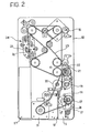
- the device for scanning cheques is shown schematically in Figure 2 .
- One or more cheques (not shown) are arranged vertically in an input receptacle 11 in which there is a feed plate 12 which urges the cheques towards a pick-up and feed roller 13.
- a first photocell 14 detects the presence of a cheque in the input receptacle 11 and, by means of an electronic control unit ECU, (shown schematically solely in Figure 5 ), activates a first motor 15 for picking up the cheque and a second motor 16 for moving the cheque forwards. Once the first motor 15 has been activated, it sets the feed roller 13 in motion by means of a transmission belt 17.
- the roller 13 is mounted on a lever 18 which is moved towards the cheques, from the position shown in solid outline to the position 13' shown in broken outline and, by rotating, causes one or more cheques to move towards a pair of motor-driven separator rollers 19, 20.
- the separator roller 20, which is contrarotatory relative to the roller 19, separates the cheques, allowing only the cheque that is disposed farthest to the right (with reference to Figure 2 ) to move forwards and pushing back the others.
- a head 22 for reading magnetic characters printed on the front of the cheque for example, a conventional electromagnetic induction head of the E13B/CMC7 type, is activated.
- the magnetic head 22 is deactivated automatically by means of the photocell 21 when the tail-end of the cheque passes beyond that photocell. When the same photocell 21 is obscured, it also causes the motor 15 for picking up the cheques to stop in order to space out the passing of the various cheques and to prevent them from being supplied consecutively, closely following one another without gaps.
- the same apparatus comprises a device for scanning other paper documents, advantageously also documents in A4 format.
- a first embodiment of the device for scanning paper documents other than cheques is shown schematically in Figure 3 .
- One or more documents D in this example, documents of A4 format, are deposited horizontally in an input receptacle 28 in the form of a tray which projects from a horizontal input slot 29 formed in the lower portion of the outer casing 10 on the side defined herein as the "front".
- the slot 29 preferably has a width (in the direction perpendicular to the direction of introduction of the documents D) greater than 210 mm to permit the introduction and scanning of documents in A4 format.
- the documents D are introduced into the slot 29 manually until they reach the region of a photocell 30 which detects the presence of a document to be scanned.
- the photocell 30 brings about activation of an electromagnetic actuator 31 which moves a pressure roller 32 mounted on a lever 33 towards a motor-driven roller 34 for picking up the document.
- the document D which is lower down, is urged into contact with the motor-driven roller 34 and is moved in the direction indicated by the arrow A, passing between a pair of contrarotating separator rollers 35, 36 which allow only one document to move forwards at a time.
- the document is then engaged by a first pair of motor-driven rollers 37, 38 which impart a constant speed of advance to the document.
- the document passes in front of a scanner photocell 39 which, when it is obscured by the document, deactivates the electromagnetic actuator 31.
- the document moves forwards, over a deflector or switch 40 associated with a biasing spring (not shown) which urges the deflector in the clockwise direction indicated in the drawing.
- the document then passes beside an image scanner 41 provided with a CIS optical sensor for scanning one of the faces of the document.
- a 210 mm CIS sensor arranged transverse the direction of movement of the documents so as to cover substantially the entire width of a sheet in A4 format or, alternatively, two 105 mm CIS sensors aligned transversely and connected to one another in cascade in accordance with methods known to persons skilled in the art, may equally well be used.
- the scanner 41 is mounted on a carousel 45 rotatable about an axis perpendicular to the path of movement of the document and the second pair of motor-driven rollers 42, 43 can be operated in order to rotate in the opposite direction to that which discharges the document onto the rear output receptacle 44.
- Front/rear scanning takes place as follows.
- the scanner photocell 39 is connected to an electronic control unit ECU ( Figure 5 ) which is arranged automatically to bring about reversal of the drive of the motor-driven rollers 42, 43 and rotation of the carousel 45 through 180° when a predetermined period of time has elapsed after the moment at which the tail-end of the document D passed the scanner photocell 39.
- the two above-mentioned commands are imparted after a period of time such that the document has completely passed the scanner 41 but is still engaged between the rollers 42, 43.
- the rotation of the carousel 45 through 180° causes the scanner 41 to be situated on the opposite side of the path of movement of the document in order to face the other face (the rear side) to be scanned, as indicated 41'.
- rollers 42, 43 By rotating in the opposite direction, the rollers 42, 43 cause the document to move backwards along its path, passing beside the scanner 41 (which will now be situated in the position 41' shown in broken outline in Figure 3 ).
- the deflector 40 When the document comes up against the deflector 40, it is guided along a deflected path 46 disposed beneath the path 47 followed by the document during the scanning of its front face.
- a third pair of motor-driven rollers 48, 49 is disposed on the deflected path 46 and conveys the document into a front output receptacle 50 disposed beneath the input receptacle 28.
- the control unit ECU automatically brings about a further rotation of the carousel 45 through 180°, thus bringing the scanner 41 back to the position shown in solid outline.
- the apparatus is thus ready to scan a new document and to repeat the above-described sequence of operations. If no further documents to be scanned are in the input receptacle, the apparatus is automatically put in a stand-by condition. Naturally, if operation solely for the front face of a document is selected, the carousel 45 will not be rotated from the position shown in solid outline.
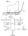
- FIG 4 shows schematically an alternative and simplified embodiment of the device for scanning paper documents other than cheques.
- a document for example in A4 format, is deposited horizontally in a front input receptacle 28 defined by a tray which projects externally from a horizontal input slot 29 situated in the lower portion of the apparatus.
- the documents are introduced into the slot 29 manually one at a time until a photocell 30 is obscured.
- the obscuring of the photocell 30 brings about the rotation of a first and of a second pair of motor-driven rollers 37, 38 and 42, 43 which pull the document forwards in the direction indicated by the arrow.
- the document thus passes over an image scanner 41 provided with a CIS optical sensor for scanning one of the faces of the document and reaches a rear output receptacle or tray 44.
- the movement of the conveyor rollers 37, 38 and 42, 43 is stopped automatically a predetermined period of time after the document has passed beyond the photocell 30.
- the information obtained by the two scanning devices of the apparatus can advantageously be managed by the PC which receives it in a manner such as to associate it and store it in a common file or in any case to "centralize” it in a suitable manner, according to the requirements of the user, for example, a bank.
- the PC which receives it in a manner such as to associate it and store it in a common file or in any case to "centralize” it in a suitable manner, according to the requirements of the user, for example, a bank.
- image scanners arranged in pairs may be used on the paths followed by the documents inside the apparatus, for substantially simultaneous scanning of both faces (front and rear) of a document, as shown in Figure 2 in which a pair of scanners 25, 26 is provided for scanning both faces of a cheque.
Landscapes
- Engineering & Computer Science (AREA)
- Signal Processing (AREA)
- Multimedia (AREA)
- Business, Economics & Management (AREA)
- Physics & Mathematics (AREA)
- General Physics & Mathematics (AREA)
- Accounting & Taxation (AREA)
- Finance (AREA)
- Strategic Management (AREA)
- General Business, Economics & Management (AREA)
- Theoretical Computer Science (AREA)
- Facsimile Scanning Arrangements (AREA)
- Image Input (AREA)
- Facsimiles In General (AREA)
- Radar Systems Or Details Thereof (AREA)
Abstract
Description
- The present invention relates to a scanner apparatus for scanning bank cheques and other paper documents, particularly documents in formats other than cheque format, of the kind defined in the preamble of Claim 1.
The apparatus is intended for use particularly advantageously at a bank counter for scanning cheques, payment receipts, and various documents. - Currently, there are known types of scanner apparatus for scanning bank cheques which comprise at least one input receptacle for receiving one or more cheques or documents to be scanned. The apparatus comprises a conveyor mechanism for conveying the cheques or documents, one at a time, from the input receptacle to an output receptacle, passing in front of an image-scanner unit for scanning one or both faces of the cheque.
US-A1-2003 0009420 discloses a scanner apparatus of this kind which is capable of scanning both sides of the cheques or documents using image reflection by a mirror. - An object of the present invention is to provide an improved scanner device for the scanning of both faces of documents.
The present invention achieves this object by means of an apparatus having the characteristics set out in the characterizing part of Claim 1. - Some preferred but non-limiting embodiments of the invention will now be described with reference to the appended drawings, in which:
-
Figure 1 is an overall perspective view of an apparatus according to the invention, -
Figure 2 is a plan view of a cheque-scanning device forming part of the apparatus ofFigure 1 , -
Figure 3 is a vertical section through a device, incorporated in the apparatus, for scanning other paper documents, -
Figure 4 is a vertical section through an alternative embodiment of the device for scanning other paper documents, -
Figure 5 is a block diagram which shows the functional relationships between various components of the devices of the apparatus. - A scanner apparatus according to the invention comprises (
Figure 1 ) anouter casing 10 in the upper portion of which there is a device for scanning cheques, whereas the lower portion houses a device for scanning paper documents of other types. - The device for scanning cheques is shown schematically in
Figure 2 . One or more cheques (not shown) are arranged vertically in aninput receptacle 11 in which there is afeed plate 12 which urges the cheques towards a pick-up andfeed roller 13. Afirst photocell 14 detects the presence of a cheque in theinput receptacle 11 and, by means of an electronic control unit ECU, (shown schematically solely inFigure 5 ), activates afirst motor 15 for picking up the cheque and a second motor 16 for moving the cheque forwards. Once thefirst motor 15 has been activated, it sets thefeed roller 13 in motion by means of atransmission belt 17. Theroller 13 is mounted on alever 18 which is moved towards the cheques, from the position shown in solid outline to the position 13' shown in broken outline and, by rotating, causes one or more cheques to move towards a pair of motor-drivenseparator rollers separator roller 20, which is contrarotatory relative to theroller 19, separates the cheques, allowing only the cheque that is disposed farthest to the right (with reference toFigure 2 ) to move forwards and pushing back the others. When the cheque which moves forwards passes in front of asecond photocell 21 and obscures it, a head 22 for reading magnetic characters printed on the front of the cheque, for example, a conventional electromagnetic induction head of the E13B/CMC7 type, is activated. The magnetic head 22 is deactivated automatically by means of thephotocell 21 when the tail-end of the cheque passes beyond that photocell. When thesame photocell 21 is obscured, it also causes themotor 15 for picking up the cheques to stop in order to space out the passing of the various cheques and to prevent them from being supplied consecutively, closely following one another without gaps. - The second motor 16 moves the cheque forwards, by means of a second
toothed feed belt 23, from the reading region of the magnetic head 22 to ascanner device 24 where the cheque passes between a pair of substantially symmetrical image-scanning units scanner device 24 are known in the art and do not need to be described in detail herein. - Finally, the cheque is deposited in an
output receptacle 27. - An important characteristic of the solution according to the present invention is that the same apparatus comprises a device for scanning other paper documents, advantageously also documents in A4 format.
- A first embodiment of the device for scanning paper documents other than cheques is shown schematically in
Figure 3 . One or more documents D, in this example, documents of A4 format, are deposited horizontally in aninput receptacle 28 in the form of a tray which projects from ahorizontal input slot 29 formed in the lower portion of theouter casing 10 on the side defined herein as the "front". Theslot 29 preferably has a width (in the direction perpendicular to the direction of introduction of the documents D) greater than 210 mm to permit the introduction and scanning of documents in A4 format. The documents D are introduced into theslot 29 manually until they reach the region of aphotocell 30 which detects the presence of a document to be scanned. Thephotocell 30 brings about activation of anelectromagnetic actuator 31 which moves apressure roller 32 mounted on alever 33 towards a motor-drivenroller 34 for picking up the document. The document D, which is lower down, is urged into contact with the motor-drivenroller 34 and is moved in the direction indicated by the arrow A, passing between a pair of contrarotatingseparator rollers rollers scanner photocell 39 which, when it is obscured by the document, deactivates theelectromagnetic actuator 31. The document moves forwards, over a deflector orswitch 40 associated with a biasing spring (not shown) which urges the deflector in the clockwise direction indicated in the drawing. The document then passes beside animage scanner 41 provided with a CIS optical sensor for scanning one of the faces of the document. For this purpose, either a 210 mm CIS sensor arranged transverse the direction of movement of the documents so as to cover substantially the entire width of a sheet in A4 format or, alternatively, two 105 mm CIS sensors aligned transversely and connected to one another in cascade in accordance with methods known to persons skilled in the art, may equally well be used. - When the document has passed the
image scanner 41, it is picked up by a second pair of motor-drivenrollers collecting tray 44, on the "rear" side of thecasing 10. - In the preferred embodiment shown in
Figure 3 , the device for scanning paper documents is arranged selectively to scan a single face or both faces (front and rear) of the document. The desired operative mode is selected by the user by means of a selection button (not shown). - For front/rear scanning, the
scanner 41 is mounted on acarousel 45 rotatable about an axis perpendicular to the path of movement of the document and the second pair of motor-drivenrollers rear output receptacle 44. - Front/rear scanning takes place as follows.
- The
scanner photocell 39 is connected to an electronic control unit ECU (Figure 5 ) which is arranged automatically to bring about reversal of the drive of the motor-drivenrollers carousel 45 through 180° when a predetermined period of time has elapsed after the moment at which the tail-end of the document D passed thescanner photocell 39. The two above-mentioned commands are imparted after a period of time such that the document has completely passed thescanner 41 but is still engaged between therollers carousel 45 through 180° causes thescanner 41 to be situated on the opposite side of the path of movement of the document in order to face the other face (the rear side) to be scanned, as indicated 41'. By rotating in the opposite direction, therollers Figure 3 ). When the document comes up against thedeflector 40, it is guided along adeflected path 46 disposed beneath thepath 47 followed by the document during the scanning of its front face. A third pair of motor-drivenrollers 48, 49 is disposed on thedeflected path 46 and conveys the document into afront output receptacle 50 disposed beneath theinput receptacle 28. - When the document passes beyond the
photocell 39 along thedeflected path 46 towards theoutput receptacle 50, the control unit ECU automatically brings about a further rotation of thecarousel 45 through 180°, thus bringing thescanner 41 back to the position shown in solid outline. The apparatus is thus ready to scan a new document and to repeat the above-described sequence of operations. If no further documents to be scanned are in the input receptacle, the apparatus is automatically put in a stand-by condition. Naturally, if operation solely for the front face of a document is selected, thecarousel 45 will not be rotated from the position shown in solid outline. -
Figure 4 shows schematically an alternative and simplified embodiment of the device for scanning paper documents other than cheques. In the variant ofFigure 4 , a document, for example in A4 format, is deposited horizontally in afront input receptacle 28 defined by a tray which projects externally from ahorizontal input slot 29 situated in the lower portion of the apparatus. The documents are introduced into theslot 29 manually one at a time until aphotocell 30 is obscured. The obscuring of thephotocell 30 brings about the rotation of a first and of a second pair of motor-drivenrollers image scanner 41 provided with a CIS optical sensor for scanning one of the faces of the document and reaches a rear output receptacle or tray 44. The movement of theconveyor rollers photocell 30. - The electronic control unit ECU supervises the operation of the apparatus as a whole and hence also the operation of all of the drive/actuator members and optical/electronic devices described above, as illustrated in the block diagram of
Figure 5 . - In particular, it will be appreciated that the apparatus of the invention uses:
- a single electronic control unit which controls the movement of all of the drive/actuator members both of the device for scanning cheques and of the device for scanning other paper documents; the same unit ECU is also operatively connected to all of the photocells and the scanning means of both of the above-mentioned devices in order to receive therefrom the signals relating to the scanning of the cheques and of the paper documents D;
- one single USB2-USB1 (universal serial bus) or Ethernet serial communication bus for transmitting the scanning data to a personal computer (PC) or to an external network, and
- a single electrical supply.
- In other words, the apparatus according to the invention is a multifunctional apparatus that incorporates within it the functions which up to now have been performed by two different sets of apparatus. Instead, the apparatus of the present invention permits a considerable saving in costs and space since the control of the movement members of the two scanning devices, the control of the optical/electronic devices of both of the devices, and the transmission of the data detected by both of the devices are entrusted to a single processing unit and to a single communication bus which are common to both devices.
- The information obtained by the two scanning devices of the apparatus can advantageously be managed by the PC which receives it in a manner such as to associate it and store it in a common file or in any case to "centralize" it in a suitable manner, according to the requirements of the user, for example, a bank. Naturally, reference to this possible field of application of the invention should not be interpreted in any way as limiting of the scope of the patent.
- The invention is not intended to be limited to the embodiments described and illustrated herein, which should be considered as examples of embodiments of the apparatus; rather, the invention may be modified with regard to the form and arrangement of parts and to the details of construction and of operation. For example, image scanners arranged in pairs may be used on the paths followed by the documents inside the apparatus, for substantially simultaneous scanning of both faces (front and rear) of a document, as shown in
Figure 2 in which a pair ofscanners
Claims (10)
- A scanner apparatus for scanning paper documents, of the type comprising a first device for scanning bank cheques, wherein the first device includes:a first input receptacle (11) for receiving at least one cheque to be scanned,at least one first image-scanner unit (25, 26) for scanning at least one of the faces of the cheque,a first output receptacle (27) for receiving the cheque after it has been scanned by the first scanner unit, anda first conveyor mechanism (15, 16, 17, 23) for conveying cheques, one at a time, from the first input receptacle (11) to the first output receptacle (27), passing in front of the first scanner unit,a second device for scanning other paper documents (D), wherein the second device includes:a second input receptacle (28) for receiving at least one paper document (D) to be scanned,at least one second image-scanner unit (41) for scanning at least one of the faces of the paper document,at least one second output receptacle (44, 50) for receiving the paper document after it has been scanned by the second scanner unit (41),a second conveyor mechanism (37, 38, 42, 43) for conveying paper documents, one at a time, from the second input receptacle (28) to the second output receptacle (44, 50), passing in front of the second scanner unit (41);the scanner apparatus being characterized in that:- the second image-scanner unit (41) is mounted so as to be rotatable (45) about an axis perpendicular to the path of movement (47) of the document (D) in order to be able to adopt a first angular position in which it is situated on one side of the path in order to scan one face of the document (D) and a second angular position (41') to which it is rotated from the first and in which it is situated on the opposite side of the path in order to scan the opposite face of the document (D),- and in that the second conveyor mechanism (37, 38, 42, 43) comprises a pair of motor-driven rollers (42, 43) which are adapted to be rotated selectively and alternatively in two opposite directions of rotation in order to move the document (D) in one direction or in the opposite direction.
- A scanner apparatus according to Claim 1, characterized in that it comprises an outer casing (10) containing the first scanning device and the second scanning device, and in that, for the second input receptacle (28), the outer casing (10) has an input slot (29) for the said paper documents (D) which has a width of at least 210 mm.
- A scanner apparatus according to Claim 1, characterized in that it comprises an electronic control unit (ECU) which is connected to the first image-scanner unit (25, 26) of the first device in order to receive signals relating to the scanning of cheques from the first unit, and to the second image-scanner unit (41) in order to receive signals relating to the scanning of the other paper documents (D) from the second unit.
- A scanner apparatus according to Claim 3, characterized in that the electronic control unit (ECU) is also operatively connected to:- photocell means (14) for detecting the presence of at least one cheque in the first input receptacle (11) of the first scanning device,- drive/actuator means (15, 16) of the first conveyor mechanism for picking up at least one cheque from the first input receptacle (11) and conveying the cheque to the first output receptacle (27), passing in front of the first scanning unit (25, 26);- photocell means (30) for detecting the presence of at least one document (D) in the second input receptacle (28) of the second scanning device,- drive/actuator means (31) of the second conveyor mechanism for picking up at least one document (D) from the second input receptacle (28) and conveying (37, 38; 42, 43; 48, 49) the document to a second output receptacle (44, 50), passing in front of the second scanner unit (41).
- A scanner apparatus according to Claim 3, characterized in that it comprises one single USB or Ethernet serial communication bus operatively connected to the electronic control unit (ECU) in order to transmit to the exterior the scanning data coming from all of the scanner units (25, 26, 41) of the apparatus.
- A scanner apparatus according to Claim 1, characterized in that the second device for scanning paper documents (D) is housed in the lower portion of the casing (10) and in that the first scanning device is disposed in the upper portion of the casing (10).
- A scanner apparatus according to Claim 1, characterized in that the second scanning device comprises an input receptacle (28) for paper documents (D), situated on a first side of the casing (10), and an output receptacle (44) disposed on a second side of the casing (10) opposite the first side.
- A scanner apparatus according to Claim 7, characterized in that the second scanning device comprises a further output receptacle (50) situated on the same, first side of the casing.
- A scanner apparatus according to Claim 1, characterized in that the pair of motor-driven rollers (42, 43) is interposed between the second, rotatable scanner unit (41, 45) and an output receptacle (44) for receiving the documents (D).
- A scanner apparatus according to Claim 1, characterized in that the second, rotatable scanner unit (41, 45) is interposed between the pair of motor-driven rollers (42, 43) and a deflector means (40) which can permit the movement of a document (D) from the second input receptacle (28) to the second scanner unit (41, 45) along a first path (47) and can deflect the document along a deflected path towards a further output receptacle (50) when the document (D) is moving in said opposite direction.
Priority Applications (2)
| Application Number | Priority Date | Filing Date | Title |
|---|---|---|---|
| EP08151218A EP1965582A1 (en) | 2003-02-07 | 2004-02-05 | Scanner apparatus for paper documents |
| CY20081101399T CY1108636T1 (en) | 2003-02-07 | 2008-12-02 | SCANNER DEVICE FOR SCANING BANK'S CHECKS AND OTHER PAPER DOCUMENTS |
Applications Claiming Priority (2)
| Application Number | Priority Date | Filing Date | Title |
|---|---|---|---|
| IT000085A ITTO20030085A1 (en) | 2003-02-07 | 2003-02-07 | SCANNER APPARATUS FOR SCANNING OF CHECKS |
| ITTO20030085 | 2003-02-07 |
Related Child Applications (1)
| Application Number | Title | Priority Date | Filing Date |
|---|---|---|---|
| EP08151218A Division EP1965582A1 (en) | 2003-02-07 | 2004-02-05 | Scanner apparatus for paper documents |
Publications (3)
| Publication Number | Publication Date |
|---|---|
| EP1445930A2 EP1445930A2 (en) | 2004-08-11 |
| EP1445930A3 EP1445930A3 (en) | 2005-01-05 |
| EP1445930B1 true EP1445930B1 (en) | 2008-09-10 |
Family
ID=32652485
Family Applications (2)
| Application Number | Title | Priority Date | Filing Date |
|---|---|---|---|
| EP04002530A Expired - Lifetime EP1445930B1 (en) | 2003-02-07 | 2004-02-05 | Scanner apparatus for scanning bank cheques and other paper documents |
| EP08151218A Withdrawn EP1965582A1 (en) | 2003-02-07 | 2004-02-05 | Scanner apparatus for paper documents |
Family Applications After (1)
| Application Number | Title | Priority Date | Filing Date |
|---|---|---|---|
| EP08151218A Withdrawn EP1965582A1 (en) | 2003-02-07 | 2004-02-05 | Scanner apparatus for paper documents |
Country Status (8)
| Country | Link |
|---|---|
| US (1) | US7397586B2 (en) |
| EP (2) | EP1445930B1 (en) |
| AT (1) | ATE408307T1 (en) |
| CY (1) | CY1108636T1 (en) |
| DE (1) | DE602004016404D1 (en) |
| ES (1) | ES2310690T3 (en) |
| IT (1) | ITTO20030085A1 (en) |
| PT (1) | PT1445930E (en) |
Families Citing this family (10)
| Publication number | Priority date | Publication date | Assignee | Title |
|---|---|---|---|---|
| TW200727676A (en) * | 2006-01-05 | 2007-07-16 | Avision Inc | Duplex scanning device having a rotatable scanning unit and duplex scanning method thereof |
| US7651083B2 (en) | 2006-09-21 | 2010-01-26 | Digital Check Corporation | Conveying apparatus and method |
| US8018632B2 (en) | 2006-11-09 | 2011-09-13 | Pertech Resources, Inc. | Scanner/imager |
| US8023718B1 (en) * | 2007-01-16 | 2011-09-20 | Burroughs Payment Systems, Inc. | Method and system for linking front and rear images in a document reader/imager |
| EP2160297B1 (en) * | 2007-06-15 | 2012-03-28 | Océ-Technologies B.V. | Imaging system |
| DE102007059410A1 (en) * | 2007-12-10 | 2009-06-25 | Wincor Nixdorf International Gmbh | Document input module |
| TW201004308A (en) * | 2008-07-04 | 2010-01-16 | Qisda Corp | Independent scanning appartus and independent scanning method |
| US20100321745A1 (en) * | 2009-06-19 | 2010-12-23 | Visioneer, Inc. | Portable battery powered multi-media duplex scanner with optional docking station |
| ITTO20110965A1 (en) | 2011-10-25 | 2013-04-26 | Panini Spa | ENTRY FEEDER DEVICE FOR A APPLIANCE FOR THE TREATMENT OF PAPER DOCUMENTS, IN PARTICULAR BANK CHECKS |
| KR20200112118A (en) * | 2019-03-21 | 2020-10-05 | 휴렛-팩커드 디벨롭먼트 컴퍼니, 엘.피. | Scanner capable of flatbed type scanning with image reading unit disposed in upper unit |
Family Cites Families (17)
| Publication number | Priority date | Publication date | Assignee | Title |
|---|---|---|---|---|
| JPS59114967A (en) * | 1982-12-21 | 1984-07-03 | Fuji Xerox Co Ltd | Reading device of both-side picture |
| JPS611164A (en) * | 1984-06-14 | 1986-01-07 | Toshiba Corp | Image forming device |
| JP2610431B2 (en) * | 1987-05-13 | 1997-05-14 | 三田工業株式会社 | Image processing device |
| US4971309A (en) * | 1988-12-02 | 1990-11-20 | Educational Testing Service | Automatic document feed mechanism |
| US5103490A (en) * | 1990-06-13 | 1992-04-07 | National Computer Systems, Inc. | Method and apparatus for storing and merging multiple optically scanned images |
| GB2251110B (en) | 1990-12-21 | 1994-05-11 | Mass Transit Railway Corp | Automatic ticket dispenser |
| US5651620A (en) * | 1993-03-30 | 1997-07-29 | Paranjpe; Suresh C. | Nonimpact printer having selectable ribbons and print heads |
| JP3163882B2 (en) * | 1994-01-19 | 2001-05-08 | ミノルタ株式会社 | Scanning device |
| US5852764A (en) * | 1996-05-14 | 1998-12-22 | Sharp Kabushiki Kaisha | Sheet post-processing apparatus |
| JP3975545B2 (en) * | 1997-03-24 | 2007-09-12 | コニカミノルタビジネステクノロジーズ株式会社 | Document scanning device and image forming apparatus including the document scanning device |
| TW344522U (en) * | 1997-10-14 | 1998-11-01 | Microtek Int Inc | Image scanner |
| DE29814558U1 (en) * | 1998-08-13 | 1998-10-08 | PLUSTEK Inc., Taipeh/T'ai-pai | Image scanner |
| US6296405B1 (en) * | 2000-01-04 | 2001-10-02 | International Business Machines Corporation | Duplex check printer using a print mechanism pivoted between document paths |
| US6434359B2 (en) * | 2000-06-06 | 2002-08-13 | Murata Kikai Kabushiki Kaisha | Image scanning apparatus having a bifurcating guide member |
| US6628433B1 (en) | 2000-07-18 | 2003-09-30 | Eastman Kodak Company | Document scanning system with dockable platen flatbed providing sheet fed and platen scanning functions |
| US6832723B2 (en) * | 2001-06-22 | 2004-12-21 | Seiko Epson Corporation | Scanner apparatus and multifunction device having a scanner |
| US7647275B2 (en) * | 2001-07-05 | 2010-01-12 | Cummins-Allison Corp. | Automated payment system and method |
-
2003
- 2003-02-07 IT IT000085A patent/ITTO20030085A1/en unknown
-
2004
- 2004-02-05 EP EP04002530A patent/EP1445930B1/en not_active Expired - Lifetime
- 2004-02-05 AT AT04002530T patent/ATE408307T1/en not_active IP Right Cessation
- 2004-02-05 ES ES04002530T patent/ES2310690T3/en not_active Expired - Lifetime
- 2004-02-05 EP EP08151218A patent/EP1965582A1/en not_active Withdrawn
- 2004-02-05 DE DE602004016404T patent/DE602004016404D1/en not_active Expired - Lifetime
- 2004-02-05 PT PT04002530T patent/PT1445930E/en unknown
- 2004-02-06 US US10/774,334 patent/US7397586B2/en not_active Expired - Fee Related
-
2008
- 2008-12-02 CY CY20081101399T patent/CY1108636T1/en unknown
Also Published As
| Publication number | Publication date |
|---|---|
| EP1445930A3 (en) | 2005-01-05 |
| EP1965582A1 (en) | 2008-09-03 |
| US20050041268A1 (en) | 2005-02-24 |
| ES2310690T3 (en) | 2009-01-16 |
| EP1445930A2 (en) | 2004-08-11 |
| PT1445930E (en) | 2008-10-23 |
| CY1108636T1 (en) | 2014-04-09 |
| ATE408307T1 (en) | 2008-09-15 |
| ITTO20030085A1 (en) | 2004-08-08 |
| DE602004016404D1 (en) | 2008-10-23 |
| US7397586B2 (en) | 2008-07-08 |
Similar Documents
| Publication | Publication Date | Title |
|---|---|---|
| US7701622B2 (en) | Media processing apparatus and scanner unit | |
| CN102673183B (en) | Compound printing equipment | |
| US20160257517A1 (en) | Reading apparatus and recording apparatus | |
| US7397586B2 (en) | Scanner apparatus for scanning bank checks and other paper documents | |
| US6738167B1 (en) | Image reading apparatus and document feeding method in image reading apparatus | |
| US7692824B2 (en) | Image reading apparatus | |
| JP6750940B2 (en) | Image reader | |
| JP2021069077A (en) | Automatic document feeding device and image processing device | |
| US9324009B2 (en) | Media processing device | |
| JP2017095228A (en) | Document conveying device | |
| JP2018104155A (en) | Sheet carrying device | |
| JP2018104158A (en) | Sheet carrier device | |
| JP6726024B2 (en) | Sheet transport device | |
| JP2021091510A (en) | Sheet conveying device, sheet processing device, image reading device and image forming device | |
| JP2007137035A (en) | Control method for print medium processing apparatus and print medium processing apparatus | |
| JP2007074644A (en) | Image forming apparatus | |
| JP3802289B2 (en) | Form capture device | |
| KR200382912Y1 (en) | multi function device for scanner and printer | |
| JP2022161610A (en) | reader | |
| JP2013026763A (en) | Reader, control method of the same, and program | |
| JPH01137384A (en) | Reading/housing device | |
| JP2011040844A (en) | Reader, control method of the reader, and program | |
| JPS62209963A (en) | Facsimile equipment | |
| WO2001011863A1 (en) | Endorser device and image reading system | |
| JPH02221042A (en) | Image forming device |
Legal Events
| Date | Code | Title | Description |
|---|---|---|---|
| PUAI | Public reference made under article 153(3) epc to a published international application that has entered the european phase |
Free format text: ORIGINAL CODE: 0009012 |
|
| AK | Designated contracting states |
Kind code of ref document: A2 Designated state(s): AT BE BG CH CY CZ DE DK EE ES FI FR GB GR HU IE IT LI LU MC NL PT RO SE SI SK TR |
|
| AX | Request for extension of the european patent |
Extension state: AL LT LV MK |
|
| PUAL | Search report despatched |
Free format text: ORIGINAL CODE: 0009013 |
|
| AK | Designated contracting states |
Kind code of ref document: A3 Designated state(s): AT BE BG CH CY CZ DE DK EE ES FI FR GB GR HU IE IT LI LU MC NL PT RO SE SI SK TR |
|
| AX | Request for extension of the european patent |
Extension state: AL LT LV MK |
|
| 17P | Request for examination filed |
Effective date: 20050701 |
|
| AKX | Designation fees paid |
Designated state(s): AT BE BG CH CY CZ DE DK EE ES FI FR GB GR HU IE IT LI LU MC NL PT RO SE SI SK TR |
|
| GRAP | Despatch of communication of intention to grant a patent |
Free format text: ORIGINAL CODE: EPIDOSNIGR1 |
|
| RIN1 | Information on inventor provided before grant (corrected) |
Inventor name: BELLOTTO, FRANCO Inventor name: PANINI, UGO |
|
| RAP1 | Party data changed (applicant data changed or rights of an application transferred) |
Owner name: PANINI S.P.A. |
|
| GRAS | Grant fee paid |
Free format text: ORIGINAL CODE: EPIDOSNIGR3 |
|
| GRAA | (expected) grant |
Free format text: ORIGINAL CODE: 0009210 |
|
| AK | Designated contracting states |
Kind code of ref document: B1 Designated state(s): AT BE BG CH CY CZ DE DK EE ES FI FR GB GR HU IE IT LI LU MC NL PT RO SE SI SK TR |
|
| REG | Reference to a national code |
Ref country code: GB Ref legal event code: FG4D |
|
| REG | Reference to a national code |
Ref country code: CH Ref legal event code: EP |
|
| REG | Reference to a national code |
Ref country code: IE Ref legal event code: FG4D |
|
| REF | Corresponds to: |
Ref document number: 602004016404 Country of ref document: DE Date of ref document: 20081023 Kind code of ref document: P |
|
| REG | Reference to a national code |
Ref country code: PT Ref legal event code: SC4A Free format text: AVAILABILITY OF NATIONAL TRANSLATION Effective date: 20081013 |
|
| REG | Reference to a national code |
Ref country code: GR Ref legal event code: EP Ref document number: 20080402631 Country of ref document: GR |
|
| REG | Reference to a national code |
Ref country code: ES Ref legal event code: FG2A Ref document number: 2310690 Country of ref document: ES Kind code of ref document: T3 |
|
| PG25 | Lapsed in a contracting state [announced via postgrant information from national office to epo] |
Ref country code: SI Free format text: LAPSE BECAUSE OF FAILURE TO SUBMIT A TRANSLATION OF THE DESCRIPTION OR TO PAY THE FEE WITHIN THE PRESCRIBED TIME-LIMIT Effective date: 20080910 Ref country code: FI Free format text: LAPSE BECAUSE OF FAILURE TO SUBMIT A TRANSLATION OF THE DESCRIPTION OR TO PAY THE FEE WITHIN THE PRESCRIBED TIME-LIMIT Effective date: 20080910 Ref country code: AT Free format text: LAPSE BECAUSE OF FAILURE TO SUBMIT A TRANSLATION OF THE DESCRIPTION OR TO PAY THE FEE WITHIN THE PRESCRIBED TIME-LIMIT Effective date: 20080910 |
|
| NLV1 | Nl: lapsed or annulled due to failure to fulfill the requirements of art. 29p and 29m of the patents act | ||
| PG25 | Lapsed in a contracting state [announced via postgrant information from national office to epo] |
Ref country code: BE Free format text: LAPSE BECAUSE OF FAILURE TO SUBMIT A TRANSLATION OF THE DESCRIPTION OR TO PAY THE FEE WITHIN THE PRESCRIBED TIME-LIMIT Effective date: 20080910 |
|
| PG25 | Lapsed in a contracting state [announced via postgrant information from national office to epo] |
Ref country code: BG Free format text: LAPSE BECAUSE OF FAILURE TO SUBMIT A TRANSLATION OF THE DESCRIPTION OR TO PAY THE FEE WITHIN THE PRESCRIBED TIME-LIMIT Effective date: 20081210 |
|
| PG25 | Lapsed in a contracting state [announced via postgrant information from national office to epo] |
Ref country code: RO Free format text: LAPSE BECAUSE OF FAILURE TO SUBMIT A TRANSLATION OF THE DESCRIPTION OR TO PAY THE FEE WITHIN THE PRESCRIBED TIME-LIMIT Effective date: 20080910 Ref country code: NL Free format text: LAPSE BECAUSE OF FAILURE TO SUBMIT A TRANSLATION OF THE DESCRIPTION OR TO PAY THE FEE WITHIN THE PRESCRIBED TIME-LIMIT Effective date: 20080910 Ref country code: SK Free format text: LAPSE BECAUSE OF FAILURE TO SUBMIT A TRANSLATION OF THE DESCRIPTION OR TO PAY THE FEE WITHIN THE PRESCRIBED TIME-LIMIT Effective date: 20080910 Ref country code: CZ Free format text: LAPSE BECAUSE OF FAILURE TO SUBMIT A TRANSLATION OF THE DESCRIPTION OR TO PAY THE FEE WITHIN THE PRESCRIBED TIME-LIMIT Effective date: 20080910 |
|
| PLBE | No opposition filed within time limit |
Free format text: ORIGINAL CODE: 0009261 |
|
| STAA | Information on the status of an ep patent application or granted ep patent |
Free format text: STATUS: NO OPPOSITION FILED WITHIN TIME LIMIT |
|
| PG25 | Lapsed in a contracting state [announced via postgrant information from national office to epo] |
Ref country code: EE Free format text: LAPSE BECAUSE OF FAILURE TO SUBMIT A TRANSLATION OF THE DESCRIPTION OR TO PAY THE FEE WITHIN THE PRESCRIBED TIME-LIMIT Effective date: 20080910 Ref country code: DK Free format text: LAPSE BECAUSE OF FAILURE TO SUBMIT A TRANSLATION OF THE DESCRIPTION OR TO PAY THE FEE WITHIN THE PRESCRIBED TIME-LIMIT Effective date: 20080910 |
|
| 26N | No opposition filed |
Effective date: 20090611 |
|
| PG25 | Lapsed in a contracting state [announced via postgrant information from national office to epo] |
Ref country code: MC Free format text: LAPSE BECAUSE OF NON-PAYMENT OF DUE FEES Effective date: 20090228 |
|
| REG | Reference to a national code |
Ref country code: CH Ref legal event code: PL |
|
| PG25 | Lapsed in a contracting state [announced via postgrant information from national office to epo] |
Ref country code: CH Free format text: LAPSE BECAUSE OF NON-PAYMENT OF DUE FEES Effective date: 20090228 Ref country code: LI Free format text: LAPSE BECAUSE OF NON-PAYMENT OF DUE FEES Effective date: 20090228 |
|
| PG25 | Lapsed in a contracting state [announced via postgrant information from national office to epo] |
Ref country code: SE Free format text: LAPSE BECAUSE OF FAILURE TO SUBMIT A TRANSLATION OF THE DESCRIPTION OR TO PAY THE FEE WITHIN THE PRESCRIBED TIME-LIMIT Effective date: 20081210 |
|
| PG25 | Lapsed in a contracting state [announced via postgrant information from national office to epo] |
Ref country code: LU Free format text: LAPSE BECAUSE OF NON-PAYMENT OF DUE FEES Effective date: 20090205 |
|
| PG25 | Lapsed in a contracting state [announced via postgrant information from national office to epo] |
Ref country code: HU Free format text: LAPSE BECAUSE OF FAILURE TO SUBMIT A TRANSLATION OF THE DESCRIPTION OR TO PAY THE FEE WITHIN THE PRESCRIBED TIME-LIMIT Effective date: 20090311 |
|
| REG | Reference to a national code |
Ref country code: FR Ref legal event code: PLFP Year of fee payment: 13 |
|
| PG25 | Lapsed in a contracting state [announced via postgrant information from national office to epo] |
Ref country code: CY Free format text: LAPSE BECAUSE OF NON-PAYMENT OF DUE FEES Effective date: 20160205 |
|
| REG | Reference to a national code |
Ref country code: FR Ref legal event code: PLFP Year of fee payment: 14 |
|
| PGFP | Annual fee paid to national office [announced via postgrant information from national office to epo] |
Ref country code: GR Payment date: 20170217 Year of fee payment: 14 Ref country code: FR Payment date: 20170228 Year of fee payment: 14 |
|
| PGFP | Annual fee paid to national office [announced via postgrant information from national office to epo] |
Ref country code: IE Payment date: 20170220 Year of fee payment: 14 Ref country code: CY Payment date: 20170120 Year of fee payment: 14 Ref country code: GB Payment date: 20170216 Year of fee payment: 14 Ref country code: PT Payment date: 20170203 Year of fee payment: 14 |
|
| PGFP | Annual fee paid to national office [announced via postgrant information from national office to epo] |
Ref country code: ES Payment date: 20170804 Year of fee payment: 14 Ref country code: ES Payment date: 20170125 Year of fee payment: 14 |
|
| PGFP | Annual fee paid to national office [announced via postgrant information from national office to epo] |
Ref country code: DE Payment date: 20170428 Year of fee payment: 14 |
|
| REG | Reference to a national code |
Ref country code: DE Ref legal event code: R119 Ref document number: 602004016404 Country of ref document: DE |
|
| GBPC | Gb: european patent ceased through non-payment of renewal fee |
Effective date: 20180205 |
|
| PG25 | Lapsed in a contracting state [announced via postgrant information from national office to epo] |
Ref country code: PT Free format text: LAPSE BECAUSE OF NON-PAYMENT OF DUE FEES Effective date: 20180806 Ref country code: CY Free format text: LAPSE BECAUSE OF NON-PAYMENT OF DUE FEES Effective date: 20180205 |
|
| PGFP | Annual fee paid to national office [announced via postgrant information from national office to epo] |
Ref country code: IT Payment date: 20180830 Year of fee payment: 15 |
|
| PG25 | Lapsed in a contracting state [announced via postgrant information from national office to epo] |
Ref country code: GR Free format text: LAPSE BECAUSE OF NON-PAYMENT OF DUE FEES Effective date: 20180904 |
|
| REG | Reference to a national code |
Ref country code: FR Ref legal event code: ST Effective date: 20181031 |
|
| REG | Reference to a national code |
Ref country code: IE Ref legal event code: MM4A |
|
| PG25 | Lapsed in a contracting state [announced via postgrant information from national office to epo] |
Ref country code: IE Free format text: LAPSE BECAUSE OF NON-PAYMENT OF DUE FEES Effective date: 20180205 Ref country code: DE Free format text: LAPSE BECAUSE OF NON-PAYMENT OF DUE FEES Effective date: 20180901 |
|
| PG25 | Lapsed in a contracting state [announced via postgrant information from national office to epo] |
Ref country code: FR Free format text: LAPSE BECAUSE OF NON-PAYMENT OF DUE FEES Effective date: 20180228 Ref country code: GB Free format text: LAPSE BECAUSE OF NON-PAYMENT OF DUE FEES Effective date: 20180205 |
|
| REG | Reference to a national code |
Ref country code: ES Ref legal event code: FD2A Effective date: 20190801 |
|
| PG25 | Lapsed in a contracting state [announced via postgrant information from national office to epo] |
Ref country code: ES Free format text: LAPSE BECAUSE OF NON-PAYMENT OF DUE FEES Effective date: 20180206 |
|
| PG25 | Lapsed in a contracting state [announced via postgrant information from national office to epo] |
Ref country code: IT Free format text: LAPSE BECAUSE OF NON-PAYMENT OF DUE FEES Effective date: 20190205 |
|
| PG25 | Lapsed in a contracting state [announced via postgrant information from national office to epo] |
Ref country code: TR Free format text: LAPSE BECAUSE OF NON-PAYMENT OF DUE FEES Effective date: 20180205 |