EP1445633A2 - Tuning tool for tunable fiber optic connector - Google Patents
Tuning tool for tunable fiber optic connector Download PDFInfo
- Publication number
- EP1445633A2 EP1445633A2 EP04250447A EP04250447A EP1445633A2 EP 1445633 A2 EP1445633 A2 EP 1445633A2 EP 04250447 A EP04250447 A EP 04250447A EP 04250447 A EP04250447 A EP 04250447A EP 1445633 A2 EP1445633 A2 EP 1445633A2
- Authority
- EP
- European Patent Office
- Prior art keywords
- tuning
- adapter
- connector
- plug
- tool
- Prior art date
- Legal status (The legal status is an assumption and is not a legal conclusion. Google has not performed a legal analysis and makes no representation as to the accuracy of the status listed.)
- Granted
Links
- 239000000835 fiber Substances 0.000 title claims abstract description 16
- 238000000034 method Methods 0.000 claims abstract description 7
- 238000003780 insertion Methods 0.000 claims description 15
- 230000037431 insertion Effects 0.000 claims description 15
- 238000005259 measurement Methods 0.000 description 4
- 239000013307 optical fiber Substances 0.000 description 4
- 238000005516 engineering process Methods 0.000 description 1
Images





Classifications
-
- G—PHYSICS
- G02—OPTICS
- G02B—OPTICAL ELEMENTS, SYSTEMS OR APPARATUS
- G02B6/00—Light guides; Structural details of arrangements comprising light guides and other optical elements, e.g. couplings
- G02B6/24—Coupling light guides
- G02B6/36—Mechanical coupling means
- G02B6/38—Mechanical coupling means having fibre to fibre mating means
- G02B6/3807—Dismountable connectors, i.e. comprising plugs
- G02B6/381—Dismountable connectors, i.e. comprising plugs of the ferrule type, e.g. fibre ends embedded in ferrules, connecting a pair of fibres
- G02B6/3825—Dismountable connectors, i.e. comprising plugs of the ferrule type, e.g. fibre ends embedded in ferrules, connecting a pair of fibres with an intermediate part, e.g. adapter, receptacle, linking two plugs
-
- G—PHYSICS
- G02—OPTICS
- G02B—OPTICAL ELEMENTS, SYSTEMS OR APPARATUS
- G02B6/00—Light guides; Structural details of arrangements comprising light guides and other optical elements, e.g. couplings
- G02B6/24—Coupling light guides
- G02B6/36—Mechanical coupling means
- G02B6/38—Mechanical coupling means having fibre to fibre mating means
- G02B6/3807—Dismountable connectors, i.e. comprising plugs
- G02B6/3833—Details of mounting fibres in ferrules; Assembly methods; Manufacture
- G02B6/3834—Means for centering or aligning the light guide within the ferrule
-
- G—PHYSICS
- G02—OPTICS
- G02B—OPTICAL ELEMENTS, SYSTEMS OR APPARATUS
- G02B6/00—Light guides; Structural details of arrangements comprising light guides and other optical elements, e.g. couplings
- G02B6/24—Coupling light guides
- G02B6/36—Mechanical coupling means
- G02B6/38—Mechanical coupling means having fibre to fibre mating means
- G02B6/3807—Dismountable connectors, i.e. comprising plugs
- G02B6/3869—Mounting ferrules to connector body, i.e. plugs
- G02B6/3871—Ferrule rotatable with respect to plug body, e.g. for setting rotational position ; Fixation of ferrules after rotation
-
- G—PHYSICS
- G02—OPTICS
- G02B—OPTICAL ELEMENTS, SYSTEMS OR APPARATUS
- G02B6/00—Light guides; Structural details of arrangements comprising light guides and other optical elements, e.g. couplings
- G02B6/24—Coupling light guides
- G02B6/36—Mechanical coupling means
- G02B6/38—Mechanical coupling means having fibre to fibre mating means
- G02B6/3807—Dismountable connectors, i.e. comprising plugs
- G02B6/3898—Tools, e.g. handheld; Tuning wrenches; Jigs used with connectors, e.g. for extracting, removing or inserting in a panel, for engaging or coupling connectors, for assembling or disassembling components within the connector, for applying clips to hold two connectors together or for crimping
Definitions
- the present invention is directed to a fiber optic connector and, more particularly, to a tuning tool for tuning a fiber optic connector.
- Tuning tools for tuning fiber optic connectors are known in the telecommunications industry.
- One such tuning tool is disclosed in U.S. Patent No. 6,287,018, assigned to Lucent Technologies.
- the '018 patent discloses a tuning index tool and a tuning wrench combination for tuning an LC type connector.
- the '018 patent teaches that once the least insertion loss incremental position of the mated connector pair is determined, the connector to be tuned is removed from the tuning tool, and a tuning wrench is then used to push the ferrule inside the connector to disengage the alignment system and rotate the ferrule of the connector clockwise or counterclockwise to "tune" the connector.
- none of the prior art tuning tools provide a tuning tool for tuning a fiber optic connector having the ability to tune a mated connector pair to each other without having to remove the connector pair from the tuning tool, without having to utilize a separate tool to finish tuning the mated connector pair, or without having to disengage the alignment system.
- a tuning tool for tuning a fiber optic connector has an outer housing, a first plug tuning disk, an inner housing received within the outer housing, a second plug tuning disk received within the inner housing, and a split sleeve.
- the first and second plug tuning disks each have an adapter extending therefrom, and the split sleeve is receivable within the first and second adapters for receiving a first ferrule and a second ferrule, respectively.
- the outer housing has an aperture therein and four snap latches for engaging four pockets on the inner housing.
- the first plug tuning disk and the inner housing are fixed in the same orientation, and the inner housing is keyed to the outer housing.
- the outer housing also has four spring latches, with each spring latch having two relieves for allowing the snap latches to flex and lock into the pockets.
- the outer housing has at least three spring fingers for applying a force to facilitate engagement of the first plug tuning disk with the inner housing.
- the first plug tuning disk has a first spline socket and a first adapter extending from a first side thereof.
- the first spline socket receives a first ferrule holder when a first connector is mated in the first adapter, and the first spline socket maintains the orientation of the first ferrule holder in the first adapter during tuning.
- the first adapter extends through the aperture in the outer housing to receive the first connector therein.
- the first plug tuning disk has eight detent ribs for engaging eight detent pockets in the inner housing and, thus, allows rotation of the first and second connectors at 45° increments to determine their optimal alignment position.
- the inner housing has a second spline socket extending from a first side thereof.
- the second spline socket receives a second ferrule holder when the second connector is mated in the second adapter, and the inner housing maintains the orientation of the second ferrule holder in the second adapter during tuning.
- the inner housing has four snap latches for securing the second plug tuning disk to the inner housing.
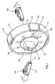
- FIG. 1 shows a tuning tool 20 for tuning a LC type connector, such as the tunable fiber optic connector disclosed in U.S. Patent Application Serial No. 10/354,273, the disclosure of which is incorporated by reference. It is likewise contemplated that the principles of this invention are also applicable to other types of connectors, such as an ST, SC, FC or FJ type connector.
- a LC type connector such as the tunable fiber optic connector disclosed in U.S. Patent Application Serial No. 10/354,273, the disclosure of which is incorporated by reference. It is likewise contemplated that the principles of this invention are also applicable to other types of connectors, such as an ST, SC, FC or FJ type connector.
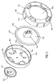
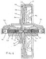
- the tuning tool 20 includes an outer housing 22, a first plug tuning disk 24, a split sleeve 26, an inner housing 28 and a second plug tuning disk 30.
- FIG. 1 shows the tuning tool 20 before insertion of a first connector 32 and a second connector 34 therein
- FIG. 2 shows a rear view of the tuning tool 20.
- FIG. 3 shows a perspective view of the tuning tool 20 after the first connector 32 and the second connector 34 have been inserted therein.
- the outer housing 22 has an aperture 36 therein.
- the outer housing 22 has four snap latches 38 for engaging four pockets 40 on the inner housing 28.
- the first plug tuning disk 24 and the inner housing 28 are fixed in the same orientation.
- the inner housing 28 is keyed to the outer housing 22.
- the outer housing 22 also has four spring latches 42, with each spring latch 42 having two relieves 44 for allowing the snap latches 38 to flex and lock into the pockets 40 in the inner housing 28.
- the outer housing 22 further includes four spring fingers 46. Upon assembly of the tuning tool 20, the spring fingers 46 apply force to keep the first plug tuning disk 24 engaged with the inner housing 28.
- the first plug tuning disk 24 has a rim face 48 for slidingly engaging the spring fingers 46 of the outer housing 22, upon assembly of the tuning tool 20.
- the first plug tuning disk 24 has a first spline socket 50 and a first adapter 52 extending from a first side 54 thereof.
- the first adapter 52 extends through the aperture 36 in the outer housing 22 and receives a first ferrule 56 of the first connector 32 therein.
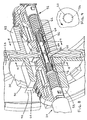
- the first ferrule 56 overtravels the midpoint of the split sleeve 26 and occupies more than half the total length of the split sleeve 26.
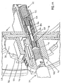
- FIG. 7 upon insertion of the first connector 32 into the first adapter 52, the first ferrule 56 overtravels the midpoint of the split sleeve 26 and occupies more than half the total length of the split sleeve 26.
- FIG. 7 upon insertion of the first connector 32 into the first adapter 52, the first ferrule 56 overtravels the midpoint of the split sleeve 26 and occupies more than half
- a second ferrule 60 engages the first ferrule 56 and pushes the first ferrule 56 back to a position occupying approximately half the total length of the split sleeve 26.
- the first spline socket 50 receives a first ferrule holder 62 having eight splines 64 spaced 45° apart around the periphery thereof.
- the first spline socket 50 matches the orientation of the first ferrule holder splines 64 and, thus, maintains the orientation of the first ferrule holder 62 in the first adapter 52 during the tuning process.
- the first plug tuning disk 24 has eight detent ribs 66 extending from a second side 68 thereof.
- the detent ribs 66 engage eight detent pockets 70 in the inner housing 28 to facilitate the tuning process.
- the detent pockets 70 and the detent ribs 66 are spaced 45° apart to allow rotating the first and second connectors 32, 34 at 45° increments to determine their optimal alignment position.
- the inner housing 28 has a second spline socket 72 extending from a first side 74 thereof.
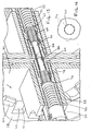
- the second spline socket 72 engages a second ferrule holder 76 having eight splines 78 spaced 45° apart around the periphery thereof, as shown in FIG. 8.
- the second spline socket 72 matches the orientation of the second ferrule holder splines 78 and, thus, the inner housing 28 maintains the orientation of the second ferrule holder 76 in the second adapter 58 during the tuning process.
- the second plug tuning disk 30 is received within the first side 74 of the inner housing 28, and four snap latches 80 secure the second plug tuning disk 30 to the inner housing 28.
- the second plug tuning disk 30 can freely rotate within the snap latches 80.
- the second plug tuning disk 30 has a second adapter 58 extending from a first side 82 thereof to receive the second ferrule 60 of the second connector 34 therein during the tuning process.
- the first connector 32 is positioned in the first adapter 52, as shown in FIG. 7, and the second connector 34 is positioned in the second adapter 58, as shown in FIG. 8, to create a mated connector pair inside the tuning tool 20.
- the first and second ferrules 56, 60 have marks 84, 86 respectively, to indicate the reference position.
- the user measures the insertion loss of the mated connector pair at the reference position.
- the reference position is not the optimal alignment position. Accordingly, and as shown in FIG. 9, the optical fiber cores of the first and second ferrules 56, 60 are offset.
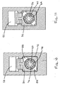
- FIGS. 10 and 11 prior to tuning, the first and second ferrule holders 62, 76 are positioned similarly in the first and second adapters 52, 58, respectively. While holding the outer housing 22 on one side of the tuning tool 20 and the first adapter 52 on the other side of the tuning tool 20, the user pulls the first plug tuning disk 24 outward to separate the first plug tuning disk 24 and the inner housing 28, and rotates the first plug tuning disk 24 45° by twisting the first adapter 52 and the outer housing 22 at the same time clockwise.
- FIG. 12 shows an end view of the tuning tool 20, as the first connector 32 is being rotated clockwise in the first adapter 52. As shown in FIG.
- the pulling and twisting action separates the two end faces of the mated connector pair and, thus, disengages the detent ribs 66 from the detent pockets 70.
- the user measures the insertion loss of the mated connector pair. This step is repeated three times in the clockwise direction, until the user has recorded insertion loss measurements from the reference position to a position 180°clockwise from the reference position.
- the user rotates the tuning tool 20 counterclockwise to the reference position.
- the user then rotates the first plug tuning disk 24 45° in a counterclockwise direction and measures the insertion loss of the mated connector pair. This step is repeated three times in the counterclockwise direction, until the user has recorded insertion loss measurements from the reference position to a position 180° counterclockwise from the reference position.
- the user may rotate the first plug tuning disk 24 at 45° increments in a clockwise or counterclockwise direction from the reference point to a point 360° from the reference point.
- rotating the mated connector pair 360° in the same direction increases the likelihood that the cable received in the connector pair could be damaged.
- the mated connector pair is rotated to its optimal alignment position. At this position, the first ferrule mark 84 is no longer aligned with the second ferrule mark 86.
- the user while holding onto the first adapter 52 and the second adapter 58, the user then rotates the second adapter 58 to align with the first adapter 52.
- Rotating the second adapter 58 causes tuning arms 88 (see FIG. 8) in the second connector housing 90 to flex and follow the spline contour of the second ferrule holder 76 and, thus, allows the second connector housing 90 to rotate around the second ferrule holder 76.
- the second ferrule 60 will remain in a fixed position when the second adapter 58 is rotated to align with the first adapter 52.
- the mated connector pair has now been tuned to each other and can be removed from the tuning tool 20.
- the optical fiber cores of the first and second ferrules 56, 60 are aligned when the mated connector pair is in its optimal alignment position.
- the disclosed invention provides a tuning tool for tuning a fiber optic connector.
- the tuning tool includes eight detent ribs and eight detent pockets spaced 45° apart around the interior of the tuning tool, to allow rotation and insertion loss measurement at 45° increments.
Landscapes
- Physics & Mathematics (AREA)
- General Physics & Mathematics (AREA)
- Optics & Photonics (AREA)
- Mechanical Coupling Of Light Guides (AREA)
- Mounting And Adjusting Of Optical Elements (AREA)
Abstract
Description
Embodiments of the invention will now be described, by way of example, with reference to the drawings; of which;
FIG. 3 shows a perspective view of the
Claims (10)
- A tuning tool for tuning a fiber optic connector comprising:an outer housing having an aperture therein;a first plug tuning disk having a first spline socket and a first adapter extending from a first side thereof, wherein the first adapter extends through the aperture and receives a first ferrule of a first connector therein;an inner housing received within the outer housing, wherein the inner housing has a second spline socket extending from a first side thereof;a second plug tuning disk received within the first side of the inner housing, the second plug tuning disk having a second adapter extending from a first side thereof to receive a second ferrule of a second connector therein; anda split sleeve receivable within the first adapter and the second adapter for receiving the first ferrule and the second ferrule, respectively.
- The tuning tool of claim 1 wherein the outer housing has four snap latches for engaging four pockets on the inner housing, or for securing the second plug tuning disk to the inner housing.
- The tuning tool of claim 2 wherein upon engagement of the snap latches in the pockets, the first plug tuning disk and the inner housing are fixed in the same orientation or wherein upon engagement of the snap latches in the pockets, the inner housing is keyed to the outer housing.
- The tuning tool of claim 2 wherein the outer housing has four spring latches, each spring latch having two relieves for allowing the snap latches to flex and lock into the pockets.
- The tuning tool of claim 1 wherein the outer housing has at least three spring fingers for applying a force to facilitate engagement of the first plug tuning disk with the inner housing, and preferably wherein the first plug tuning disk has a rim face for slidingly engaging the spring fingers.
- The tuning tool of claim 1 wherein the first spline socket receives a first ferrule holder having a plurality of splines when the first connector is mated in the first adapter, and preferably wherein the first spline socket maintains the orientation of the first ferrule holder in the first adapter during tuning.
- The tuning tool of claim 1 wherein the first plug tuning disk has eight detent ribs for engaging eight detent pockets in the inner housing, and preferably wherein the eight detent pockets and the eight detent ribs allow rotating the first and second connectors at 45 degree
increments to determine their optimal alignment position. - The tuning tool of claim 1 wherein the second spline socket receives a second ferrule holder having a plurality of splines when the second connector is mated in the second adapter, and preferably wherein the inner housing maintains the orientation of the second ferrule holder in the second adapter during tuning.
- A method of tuning a fiber optic connector comprising the steps of:providing a tuning tool having an outer housing, a first plug tuning disk having a first adapter, an inner housing received within the outer housing, a second plug tuning disk received within the inner housing, the second plug tuning disk having a second adapter, and a split sleeve receivable within the first adapter and the second adapter for receiving a first ferrule and a second ferrule, respectively;positioning a first connector in the first adapter and a second connector in the second adapter to create a mated connector pair inside the tuning tool;aligning the second adapter to the first adapter to create a reference position; measuring insertion loss of the connector pair at the reference position;rotating the first plug tuning disk 45 degrees in a first direction and measuring insertion loss of the connector pair;repeating the step of rotating and measuring in the first direction three times; rotating the tuning tool in a second direction to the reference position;rotating the first plug tuning disk 45 degrees in the second direction and measuring insertion loss of the connector pair;repeating the step of rotating and measuring in the second direction three times; rotating the connector pair to its optimal performance position; androtating the second adapter to align with the first adapter to tune the connector pair.
- The method of claim 9 further comprising the step of removing the connector pair from the tuning tool.
Applications Claiming Priority (2)
| Application Number | Priority Date | Filing Date | Title |
|---|---|---|---|
| US10/354,388 US6859604B2 (en) | 2003-01-30 | 2003-01-30 | Tuning tool for tunable fiber optic connector |
| US354388 | 2003-01-30 |
Publications (3)
| Publication Number | Publication Date |
|---|---|
| EP1445633A2 true EP1445633A2 (en) | 2004-08-11 |
| EP1445633A3 EP1445633A3 (en) | 2005-01-19 |
| EP1445633B1 EP1445633B1 (en) | 2006-11-08 |
Family
ID=32655543
Family Applications (1)
| Application Number | Title | Priority Date | Filing Date |
|---|---|---|---|
| EP04250447A Expired - Lifetime EP1445633B1 (en) | 2003-01-30 | 2004-01-28 | Tuning tool for tunable fiber optic connector |
Country Status (6)
| Country | Link |
|---|---|
| US (1) | US6859604B2 (en) |
| EP (1) | EP1445633B1 (en) |
| JP (1) | JP4271049B2 (en) |
| CN (1) | CN100399086C (en) |
| AT (1) | ATE344934T1 (en) |
| DE (1) | DE602004003075T2 (en) |
Cited By (2)
| Publication number | Priority date | Publication date | Assignee | Title |
|---|---|---|---|---|
| EP1671169A4 (en) * | 2003-09-22 | 2010-09-01 | Belden Cdt Canada Inc | Keyed fibre optic connector |
| EP2345113A1 (en) * | 2008-09-26 | 2011-07-20 | Tyco Electronics Corporation | Rotationally adjustable connector assembly |
Families Citing this family (12)
| Publication number | Priority date | Publication date | Assignee | Title |
|---|---|---|---|---|
| US7674046B2 (en) * | 2003-09-22 | 2010-03-09 | Belden Cdt (Canada) Inc. | Fibre optic connector keying system |
| US7346256B2 (en) * | 2004-11-04 | 2008-03-18 | Panduit Corp. | Re-terminable LC connector assembly and cam termination tool |
| CN100573208C (en) * | 2004-11-04 | 2009-12-23 | 潘都依特有限公司 | Reterminable LC Connector Assembly and Cam Termination Tool |
| US7509000B2 (en) * | 2006-03-20 | 2009-03-24 | Baker Hughes Incorporated | Downhole optic fiber wet connect system and method |
| US7465103B1 (en) * | 2008-06-25 | 2008-12-16 | Comosss Electronic Co., Ltd. | Plastic fiber cable coupling structure |
| JP5448885B2 (en) * | 2010-01-28 | 2014-03-19 | 富士フイルム株式会社 | Medical equipment and endoscope device |
| WO2013173726A1 (en) | 2012-05-18 | 2013-11-21 | Adc Telecommunications, Inc. | Connectors and adapters with auto-latching features |
| US9075205B2 (en) | 2012-07-11 | 2015-07-07 | Tyco Electronics Corporation | Connectors and adapters with auto-latching features |
| US9146362B2 (en) * | 2012-09-21 | 2015-09-29 | Adc Telecommunications, Inc. | Insertion and removal tool for a fiber optic ferrule alignment sleeve |
| MX2017014377A (en) | 2015-05-15 | 2018-08-15 | Adc Telecommunications Shanghai Distrib Co Ltd | Alignment sleeve assembly and optical fibre adapter. |
| JP7261778B2 (en) * | 2020-09-29 | 2023-04-20 | Kddi株式会社 | Multi-core optical fiber splicer |
| CN115774305B (en) * | 2021-09-07 | 2026-01-16 | 华为技术有限公司 | A method for manufacturing fiber optic connectors and fiber optic ferrules |
Family Cites Families (13)
| Publication number | Priority date | Publication date | Assignee | Title |
|---|---|---|---|---|
| US4889406A (en) * | 1985-04-11 | 1989-12-26 | Sezerman Omur M | Tilt adjustable optical fibre connectors |
| CA1258786A (en) * | 1985-04-11 | 1989-08-29 | Omur M. Sezerman | Tilt adjustable optical fibre connectors |
| CA1325122C (en) * | 1988-06-23 | 1993-12-14 | Omur M. Sezerman | Tilt adjustable optical fibre connectors |
| US5481634A (en) * | 1994-06-24 | 1996-01-02 | At&T Corp. | Connector for optical fiber |
| US6076975A (en) * | 1998-10-15 | 2000-06-20 | Molex Incorporated | Fiber optic connector assembly |
| JP2000130447A (en) * | 1998-10-28 | 2000-05-12 | Nsk Ltd | Rolling bearing |
| US6524014B2 (en) * | 1999-04-01 | 2003-02-25 | Fitel Usa Corp. | Universal modular optical fiber buildout |
| US6238101B1 (en) * | 1999-07-08 | 2001-05-29 | Molex Incorporated | Tunable fiber optic connector |
| US6287018B1 (en) * | 1999-07-28 | 2001-09-11 | Lucent Technologies Inc. | Tunable optical fiber connector |
| US6464402B1 (en) * | 1999-07-28 | 2002-10-15 | Fitel Usa Corp. | Optical fiber connector tuning index tool |
| US6155146A (en) * | 1999-07-28 | 2000-12-05 | Lucent Technologies Inc. | Optical fiber connector tuning wrench |
| US6254278B1 (en) * | 1999-10-06 | 2001-07-03 | Lucent Technologies Inc. | Optical fiber tunable connector adapter |
| US6367984B1 (en) * | 1999-11-10 | 2002-04-09 | Lucent Technologies, Inc. | Optical fiber adapter |
-
2003
- 2003-01-30 US US10/354,388 patent/US6859604B2/en not_active Expired - Lifetime
-
2004
- 2004-01-28 AT AT04250447T patent/ATE344934T1/en not_active IP Right Cessation
- 2004-01-28 EP EP04250447A patent/EP1445633B1/en not_active Expired - Lifetime
- 2004-01-28 DE DE602004003075T patent/DE602004003075T2/en not_active Expired - Lifetime
- 2004-01-30 CN CNB2004100033976A patent/CN100399086C/en not_active Expired - Fee Related
- 2004-01-30 JP JP2004022442A patent/JP4271049B2/en not_active Expired - Lifetime
Cited By (2)
| Publication number | Priority date | Publication date | Assignee | Title |
|---|---|---|---|---|
| EP1671169A4 (en) * | 2003-09-22 | 2010-09-01 | Belden Cdt Canada Inc | Keyed fibre optic connector |
| EP2345113A1 (en) * | 2008-09-26 | 2011-07-20 | Tyco Electronics Corporation | Rotationally adjustable connector assembly |
Also Published As
| Publication number | Publication date |
|---|---|
| ATE344934T1 (en) | 2006-11-15 |
| EP1445633A3 (en) | 2005-01-19 |
| CN100399086C (en) | 2008-07-02 |
| US6859604B2 (en) | 2005-02-22 |
| DE602004003075D1 (en) | 2006-12-21 |
| JP2004272222A (en) | 2004-09-30 |
| US20040151464A1 (en) | 2004-08-05 |
| JP4271049B2 (en) | 2009-06-03 |
| DE602004003075T2 (en) | 2007-06-21 |
| CN1519601A (en) | 2004-08-11 |
| EP1445633B1 (en) | 2006-11-08 |
Similar Documents
| Publication | Publication Date | Title |
|---|---|---|
| EP1445633B1 (en) | Tuning tool for tunable fiber optic connector | |
| US10663675B2 (en) | Tuned fiber optic connectors | |
| US6634796B2 (en) | Polarity reversal for fiber optic connections | |
| US6695489B2 (en) | Tunable fiber optic connector and method for assembling | |
| US8137002B2 (en) | Mechanical interface converter for making non-ruggedized fiber optic connectors compatible with a ruggedized fiber optic adapter | |
| EP1443350B1 (en) | Tunable fiber optic connector | |
| CN101846773B (en) | Optical lc connector assembly and cam termination tool | |
| EP0366346B1 (en) | Optical connector | |
| EP1072914A3 (en) | Optical fiber connector tuning tool for eccentricity optimisation | |
| EP0827595A1 (en) | Device with internal features for rotational alignment of non-cylindrically symmetrical optical elements | |
| US6283640B1 (en) | Tunable optical fiber buildout | |
| US11726269B2 (en) | Lockable MPO connector for securing within a port of an adapter having a unique removal key | |
| JP3752331B2 (en) | Multi-fiber optical connector | |
| US6913396B2 (en) | Tunable fiber optic connector and device and method for tuning a connector | |
| JPH02171707A (en) | Optical connector | |
| EP1041414B1 (en) | Sleeve holder for optical fiber buildout | |
| WO2024145684A1 (en) | Optical fiber connector configured to be tuned so as to minimize signal transmission loss |
Legal Events
| Date | Code | Title | Description |
|---|---|---|---|
| PUAI | Public reference made under article 153(3) epc to a published international application that has entered the european phase |
Free format text: ORIGINAL CODE: 0009012 |
|
| AK | Designated contracting states |
Kind code of ref document: A2 Designated state(s): AT BE BG CH CY CZ DE DK EE ES FI FR GB GR HU IE IT LI LU MC NL PT RO SE SI SK TR |
|
| AX | Request for extension of the european patent |
Extension state: AL LT LV MK |
|
| PUAL | Search report despatched |
Free format text: ORIGINAL CODE: 0009013 |
|
| AK | Designated contracting states |
Kind code of ref document: A3 Designated state(s): AT BE BG CH CY CZ DE DK EE ES FI FR GB GR HU IE IT LI LU MC NL PT RO SE SI SK TR |
|
| AX | Request for extension of the european patent |
Extension state: AL LT LV MK |
|
| 17P | Request for examination filed |
Effective date: 20050624 |
|
| AKX | Designation fees paid |
Designated state(s): AT BE BG CH CY CZ DE DK EE ES FI FR GB GR HU IE IT LI LU MC NL PT RO SE SI SK TR |
|
| GRAP | Despatch of communication of intention to grant a patent |
Free format text: ORIGINAL CODE: EPIDOSNIGR1 |
|
| GRAS | Grant fee paid |
Free format text: ORIGINAL CODE: EPIDOSNIGR3 |
|
| GRAA | (expected) grant |
Free format text: ORIGINAL CODE: 0009210 |
|
| AK | Designated contracting states |
Kind code of ref document: B1 Designated state(s): AT BE BG CH CY CZ DE DK EE ES FI FR GB GR HU IE IT LI LU MC NL PT RO SE SI SK TR |
|
| PG25 | Lapsed in a contracting state [announced via postgrant information from national office to epo] |
Ref country code: IT Free format text: LAPSE BECAUSE OF FAILURE TO SUBMIT A TRANSLATION OF THE DESCRIPTION OR TO PAY THE FEE WITHIN THE PRESCRIBED TIME-LIMIT;WARNING: LAPSES OF ITALIAN PATENTS WITH EFFECTIVE DATE BEFORE 2007 MAY HAVE OCCURRED AT ANY TIME BEFORE 2007. THE CORRECT EFFECTIVE DATE MAY BE DIFFERENT FROM THE ONE RECORDED. Effective date: 20061108 Ref country code: RO Free format text: LAPSE BECAUSE OF FAILURE TO SUBMIT A TRANSLATION OF THE DESCRIPTION OR TO PAY THE FEE WITHIN THE PRESCRIBED TIME-LIMIT Effective date: 20061108 Ref country code: LI Free format text: LAPSE BECAUSE OF FAILURE TO SUBMIT A TRANSLATION OF THE DESCRIPTION OR TO PAY THE FEE WITHIN THE PRESCRIBED TIME-LIMIT Effective date: 20061108 Ref country code: FI Free format text: LAPSE BECAUSE OF FAILURE TO SUBMIT A TRANSLATION OF THE DESCRIPTION OR TO PAY THE FEE WITHIN THE PRESCRIBED TIME-LIMIT Effective date: 20061108 Ref country code: SK Free format text: LAPSE BECAUSE OF FAILURE TO SUBMIT A TRANSLATION OF THE DESCRIPTION OR TO PAY THE FEE WITHIN THE PRESCRIBED TIME-LIMIT Effective date: 20061108 Ref country code: CH Free format text: LAPSE BECAUSE OF FAILURE TO SUBMIT A TRANSLATION OF THE DESCRIPTION OR TO PAY THE FEE WITHIN THE PRESCRIBED TIME-LIMIT Effective date: 20061108 Ref country code: NL Free format text: LAPSE BECAUSE OF FAILURE TO SUBMIT A TRANSLATION OF THE DESCRIPTION OR TO PAY THE FEE WITHIN THE PRESCRIBED TIME-LIMIT Effective date: 20061108 Ref country code: CZ Free format text: LAPSE BECAUSE OF FAILURE TO SUBMIT A TRANSLATION OF THE DESCRIPTION OR TO PAY THE FEE WITHIN THE PRESCRIBED TIME-LIMIT Effective date: 20061108 Ref country code: AT Free format text: LAPSE BECAUSE OF FAILURE TO SUBMIT A TRANSLATION OF THE DESCRIPTION OR TO PAY THE FEE WITHIN THE PRESCRIBED TIME-LIMIT Effective date: 20061108 Ref country code: SI Free format text: LAPSE BECAUSE OF FAILURE TO SUBMIT A TRANSLATION OF THE DESCRIPTION OR TO PAY THE FEE WITHIN THE PRESCRIBED TIME-LIMIT Effective date: 20061108 Ref country code: BE Free format text: LAPSE BECAUSE OF FAILURE TO SUBMIT A TRANSLATION OF THE DESCRIPTION OR TO PAY THE FEE WITHIN THE PRESCRIBED TIME-LIMIT Effective date: 20061108 |
|
| REG | Reference to a national code |
Ref country code: GB Ref legal event code: FG4D |
|
| REG | Reference to a national code |
Ref country code: CH Ref legal event code: EP |
|
| REG | Reference to a national code |
Ref country code: IE Ref legal event code: FG4D |
|
| REF | Corresponds to: |
Ref document number: 602004003075 Country of ref document: DE Date of ref document: 20061221 Kind code of ref document: P |
|
| PG25 | Lapsed in a contracting state [announced via postgrant information from national office to epo] |
Ref country code: MC Free format text: LAPSE BECAUSE OF NON-PAYMENT OF DUE FEES Effective date: 20070131 |
|
| PG25 | Lapsed in a contracting state [announced via postgrant information from national office to epo] |
Ref country code: SE Free format text: LAPSE BECAUSE OF FAILURE TO SUBMIT A TRANSLATION OF THE DESCRIPTION OR TO PAY THE FEE WITHIN THE PRESCRIBED TIME-LIMIT Effective date: 20070208 Ref country code: DK Free format text: LAPSE BECAUSE OF FAILURE TO SUBMIT A TRANSLATION OF THE DESCRIPTION OR TO PAY THE FEE WITHIN THE PRESCRIBED TIME-LIMIT Effective date: 20070208 Ref country code: BG Free format text: LAPSE BECAUSE OF FAILURE TO SUBMIT A TRANSLATION OF THE DESCRIPTION OR TO PAY THE FEE WITHIN THE PRESCRIBED TIME-LIMIT Effective date: 20070208 |
|
| PG25 | Lapsed in a contracting state [announced via postgrant information from national office to epo] |
Ref country code: ES Free format text: LAPSE BECAUSE OF FAILURE TO SUBMIT A TRANSLATION OF THE DESCRIPTION OR TO PAY THE FEE WITHIN THE PRESCRIBED TIME-LIMIT Effective date: 20070219 |
|
| PG25 | Lapsed in a contracting state [announced via postgrant information from national office to epo] |
Ref country code: PT Free format text: LAPSE BECAUSE OF FAILURE TO SUBMIT A TRANSLATION OF THE DESCRIPTION OR TO PAY THE FEE WITHIN THE PRESCRIBED TIME-LIMIT Effective date: 20070409 |
|
| NLV1 | Nl: lapsed or annulled due to failure to fulfill the requirements of art. 29p and 29m of the patents act | ||
| ET | Fr: translation filed | ||
| REG | Reference to a national code |
Ref country code: CH Ref legal event code: PL |
|
| PLBE | No opposition filed within time limit |
Free format text: ORIGINAL CODE: 0009261 |
|
| STAA | Information on the status of an ep patent application or granted ep patent |
Free format text: STATUS: NO OPPOSITION FILED WITHIN TIME LIMIT |
|
| 26N | No opposition filed |
Effective date: 20070809 |
|
| PG25 | Lapsed in a contracting state [announced via postgrant information from national office to epo] |
Ref country code: IE Free format text: LAPSE BECAUSE OF NON-PAYMENT OF DUE FEES Effective date: 20070129 |
|
| PG25 | Lapsed in a contracting state [announced via postgrant information from national office to epo] |
Ref country code: GR Free format text: LAPSE BECAUSE OF FAILURE TO SUBMIT A TRANSLATION OF THE DESCRIPTION OR TO PAY THE FEE WITHIN THE PRESCRIBED TIME-LIMIT Effective date: 20070209 |
|
| PG25 | Lapsed in a contracting state [announced via postgrant information from national office to epo] |
Ref country code: EE Free format text: LAPSE BECAUSE OF FAILURE TO SUBMIT A TRANSLATION OF THE DESCRIPTION OR TO PAY THE FEE WITHIN THE PRESCRIBED TIME-LIMIT Effective date: 20061108 |
|
| PG25 | Lapsed in a contracting state [announced via postgrant information from national office to epo] |
Ref country code: CY Free format text: LAPSE BECAUSE OF FAILURE TO SUBMIT A TRANSLATION OF THE DESCRIPTION OR TO PAY THE FEE WITHIN THE PRESCRIBED TIME-LIMIT Effective date: 20061108 Ref country code: LU Free format text: LAPSE BECAUSE OF NON-PAYMENT OF DUE FEES Effective date: 20070128 |
|
| PG25 | Lapsed in a contracting state [announced via postgrant information from national office to epo] |
Ref country code: TR Free format text: LAPSE BECAUSE OF FAILURE TO SUBMIT A TRANSLATION OF THE DESCRIPTION OR TO PAY THE FEE WITHIN THE PRESCRIBED TIME-LIMIT Effective date: 20061108 Ref country code: HU Free format text: LAPSE BECAUSE OF FAILURE TO SUBMIT A TRANSLATION OF THE DESCRIPTION OR TO PAY THE FEE WITHIN THE PRESCRIBED TIME-LIMIT Effective date: 20070509 |
|
| PGFP | Annual fee paid to national office [announced via postgrant information from national office to epo] |
Ref country code: FR Payment date: 20110128 Year of fee payment: 8 |
|
| PGFP | Annual fee paid to national office [announced via postgrant information from national office to epo] |
Ref country code: GB Payment date: 20110126 Year of fee payment: 8 |
|
| PGFP | Annual fee paid to national office [announced via postgrant information from national office to epo] |
Ref country code: DE Payment date: 20120127 Year of fee payment: 9 |
|
| GBPC | Gb: european patent ceased through non-payment of renewal fee |
Effective date: 20120128 |
|
| REG | Reference to a national code |
Ref country code: FR Ref legal event code: ST Effective date: 20120928 |
|
| PG25 | Lapsed in a contracting state [announced via postgrant information from national office to epo] |
Ref country code: GB Free format text: LAPSE BECAUSE OF NON-PAYMENT OF DUE FEES Effective date: 20120128 |
|
| PG25 | Lapsed in a contracting state [announced via postgrant information from national office to epo] |
Ref country code: FR Free format text: LAPSE BECAUSE OF NON-PAYMENT OF DUE FEES Effective date: 20120131 |
|
| PG25 | Lapsed in a contracting state [announced via postgrant information from national office to epo] |
Ref country code: DE Free format text: LAPSE BECAUSE OF NON-PAYMENT OF DUE FEES Effective date: 20130801 |
|
| REG | Reference to a national code |
Ref country code: DE Ref legal event code: R119 Ref document number: 602004003075 Country of ref document: DE Effective date: 20130801 |