Technical Field
The present invention relates to a refrigerating apparatus having supercritical
refrigerating cycles using as a refrigerant a natural system refrigerant, which apparatus is
suitable to be used for, for example, a heat-source unit of heat pump type hot-water supply
equipment.
Background Art
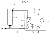
Heat pump type hot-water supply equipment is equipped with, in general, a tank
unit 71 having a hot-water reservoir tank 70, and a heat-source unit 73 having a refrigerant
circuit 72, as shown in Fig. 7. The refrigerant circuit 72 is so configured as to connect a
compressor 74, a hydrothermal exchanger 75, an expansion valve 77, and an evaporator 78
in order. The tank unit 71 includes the hot-water reservoir tank 70 and a circulation path
79. The circulation path 79 is provided with a pump 80 for water circulation and a heat
exchange path 81 which constitutes a part of the hydrothermal exchanger 75.
Here, the operation of the aforementioned heat pump type hot-water supply
equipment will be described.
First, the compressor 74 is driven while the pump 80 for water circulation is also
driven (operated). Then, stored water (hot water) flows out from the water intake
provided at the bottom of the hot-water reservoir tank 70 to the circulation path 79, and the
hot-water flown out flows through the heat exchange path 81. Here, the hot water
flowing through the heat exchange path 81 is heated (boiled) by the hydrothermal
exchanger 75. The hot water heated flows into the top portion of the hot-water reservoir
tank 70 from the hot-water inlet. Thereby, the hot water of high temperature is stored in
the hot-water reservoir tank 70.
Conventionally, as a refrigerant circulating the refrigerant circuit, such a
refrigerant as dichlorodifluoromethane (R-12) or chlorodifluoromethane (R-22) was used.
However, from the point of preventing destruction of the ozone layer, preventing
environmental pollution, and the like, an alternative refrigerant such as 1,1,1,2-tetrafluoro
ethane (R-134a) has been used as a refrigerant. Still, the alternative refrigerant such as R-134a
has a problem of having a high ability to cause a greenhouse effect or the like.
Therefore, it has been gradually recommended in recent years to use a natural system
refrigerant, which is free of the aforementioned defect, as a refrigerant. As a natural
system refrigerant of this kind, carbon dioxide, for example, is well known.
As the outside air temperature varies along with the season's transition, a load
change occurs in the aforementioned equipment. According to the load change, the
refrigerant cycles also change. This means that the preferable amount of circulated
refrigerant is different for every season. Thus, it has been difficult to operate with the
optimum amount of circulated refrigerant unless some measures are taken. If the actual
amount of the circulated refrigerant is less than the optimum amount of the circulated
refrigerant, the superheated refrigerant is sucked into the compressor 74, causing the
compressor 74 to be operated in the excessively superheated condition. In contrast, if the
actual amount of the circulated refrigerant exceeds the optimum amount of the circulated
refrigerant, the refrigerant, which has not been evaporated completely, is sucked into the
compressor 74, causing the compressor 74 to be operated in the wet condition. As a result,
the reliability of the compressor 74 is degraded.
The present invention is developed to solve the aforementioned conventional
problems. The object of the present invention is to provide a technique which enables to
operate with a proper amount of circulated refrigerant by controlling the amount, and
prevents an excessive superheat operation or a wet operation.
Disclosure of the Invention
A first refrigerating apparatus devised by the present invention comprises: a
supercritical freezing cycle R having a compressor 25 for compressing a refrigerant to a
pressure higher than the critical pressure, a gas cooler 26, a decompressing mechanism 27
and an evaporator 28, and using as the refrigerant a natural system refrigerant; a receiver
43 provided to the high-pressure side of the supercritical freezing cycle R; a receiver
temperature detector 50a for detecting the temperature of the receiver 43; and a controller
55 for controlling the amount of the circulated refrigerant by bringing the temperature of
the receiver 43 detected by the receiver temperature detector 50a close to a target receiver
temperature.
In the aforementioned first refrigerating apparatus, the controller 55 controls the
temperature of the receiver 43 so as to come close to the target receiver temperature set
corresponding to, for example, the season, whereby the refrigerant temperature in the
receiver 43 can be adjusted. This enables to control the density of the refrigerant in the
receiver 43. As a result, the refrigerant amount stored in the receiver 43 can be adjusted.
Therefore, the refrigerant amount stored in the receiver 43 can be made to the amount
corresponding to the season, whereby the amount of the circulated refrigerant can be made
to the amount corresponding to the season. Therefore, an excessive superheat operation
and a wet operation can be prevented.
A second refrigerating apparatus devised by the present invention comprises an
outside air temperature detector 53a for detecting the outside air temperature, and the
controller 55 thereof is so configured as to calculate the target receiver temperature based
on the outside air temperature detected by the outside air temperature detector 53a.
In the aforementioned second refrigerating apparatus, the controller 55 calculates
the target receiver temperature based on the outside air temperature serving as an index for
controlling the amount of the circulated refrigerant. Therefore, it is ensured that the
amount of the circulated refrigerant is made to the expected amount (for example, the
amount of the circulated refrigerant corresponding to the season).
Further, since the outside air temperature is detected by the outside air
temperature detector 53a, the outside air temperature can be detected without a
computation. Therefore, if the target receiver temperature is calculated based on the
outside air temperature, it is possible to simplify the computation for controlling the
amount of the circulated refrigerant.
A third refrigerating apparatus devised by the present invention comprises a
superheat degree detector 51a, 52a, 55 for detecting the superheat degree of the refrigerant
at the outlet of the evaporator 28, and the controller 55 thereof is so configured as to
calculate the target receiver temperature based on the superheat degree detected by the
superheat degree detector 51a, 52a, 55.
In the third refrigerating apparatus, the controller 55 calculates the target receiver
temperature based on the superheat degree serving as an index for controlling the amount
of the circulated refrigerant. Therefore, it is ensured that the amount of the circulated
refrigerant is made to the expected amount (for example, the amount of the circulated
refrigerant corresponding to the season).
Further, the magnitude of the superheat degree has a close relationship with the
degree of the superheat operation. Therefore, if the target receiver temperature is
calculated based on the superheat degree, it is possible to control the amount of the
circulated refrigerant with high precision.
A forth refrigerating apparatus devised by the present invention comprises, an
outside air temperature detector 53a for detecting the outside air temperature, and a
superheat degree detector 51a, 52a, 55 for detecting the superheat degree of the refrigerant
at the outlet of the evaporator 28, and the controller 55 thereof is so configured as to
calculate the target receiver temperature based on the outside air temperature detected by
the outside air temperature detector 53a and the superheat degree detected by the superheat
degree detector 51a, 52a, 55.
In the aforementioned forth refrigerating apparatus, the controller 55 calculates
the target receiver temperature based on the outside air temperature and the superheat
degree serving as indexes for controlling the amount of the circulated refrigerant.
Therefore, it is ensured that the amount of the circulated refrigerant is made to the expected
amount (for example, the amount of the circulated refrigerant corresponding to the season).
Further, if the target receiver temperature is calculated based on the outside air
temperature and the superheat degree, the target receiver temperature is calculated based
on the two indexes, whereby it is possible to control the amount of the circulated
refrigerant with high precision.
A fifth refrigerating apparatus devised by the present invention comprises an
adjusting valve 44 for adjusting the amount of the refrigerant flowing through the inside of
the receiver 43, and the controller 55 thereof is so configured as to adjust the opening of
the adjusting valve 44 to thereby bring the temperature of the receiver 43 detected by the
receiver temperature detector 50a close to the target receiver temperature
In the aforementioned fifth refrigerating apparatus, the controller 55 brings the
temperature of the receiver 43 close to the target receiver temperature by adjusting the
opening of the adjusting valve 44. Therefore, with a simple control of adjusting the
opening of the adjusting valve 44, the amount of the circulated refrigerant can be
controlled.
A sixth refrigerating apparatus devised by the present invention comprises: a
supercritical freezing cycle R having a compressor 25 for compressing a refrigerant to a
pressure higher than the critical pressure, a gas cooler 26, a decompressing mechanism 27
and an evaporator 28, and using as the refrigerant a natural system refrigerant; a receiver
43 provided to the high-pressure side of the supercritical freezing cycle R; an adjusting
valve 44 for adjusting the amount of the refrigerant flowing through the inside of the
receiver 43; an outside air temperature detector 53a for detecting the outside air
temperature; and a controller 55 for controlling the amount of the circulated refrigerant by
adjusting the opening of the adjusting valve 44 based on the outside air temperature
detected by the outside air temperature detector 53a.
In the aforementioned sixth refrigerating apparatus, the controller 55 adjusts the
opening of the adjusting valve 44 based on the outside air temperature serving as an index
for controlling the amount of the circulated refrigerant. Thereby, the refrigerant amount
stored in the receiver 43 (refrigerant amount flowing through the inside of the receiver 43)
can be adjusted. Therefore, the amount of the circulated refrigerant can be made to the
expected amount, whereby an excessive superheat operation and a wet operation can be
prevented.
Further, since the outside air temperature is detected by the outside air
temperature detector 53a, the outside air temperature can be detected without a
computation. Therefore, if the opening of the adjusting valve 44 is adjusted based on the
outside air temperature, it is possible to simplify the computation for controlling the
amount of the circulated refrigerant.
A seventh refrigerating apparatus devised by the present invention comprises: a
supercritical freezing cycle R having a compressor 25 for compressing a refrigerant to a
pressure higher than the critical pressure, a gas cooler 26, a decompressing mechanism 27
and an evaporator 28, and using as the refrigerant a natural system refrigerant; a receiver
43 provided to the high-pressure side of the supercritical freezing cycle R; an adjusting
valve 44 for adjusting the amount of the refrigerant flowing through the inside of the
receiver 43; a superheat degree detector 51a, 52a, 55 for detecting the superheat degree of
the refrigerant at the outlet of the evaporator 28; and a controller 55 for controlling the
amount of the circulated refrigerant by adjusting the opening of the adjusting valve 44
based on the superheat degree detected by the superheat degree detector 51a, 52a, 55.
In the aforementioned seventh refrigerating apparatus, the controller 55 adjusts
the opening of the adjusting valve 44 based on the superheat degree serving as an index for
controlling the amount of the circulated refrigerant. Thereby, the refrigerant amount
stored in the receiver 43 (refrigerant amount flowing through the inside of the receiver 43)
can be adjusted. Therefore, the amount of the circulated refrigerant can be made to the
expected amount, whereby an excessive superheat operation and a wet operation can be
prevented.
Further, the magnitude of the superheat degree has a close relationship with the
degree of the superheat operation. Therefore, if the opening of the adjusting valve 44 is
adjusted based on the superheat degree, the amount of the circulated refrigerant can be
controlled with high precision.
An eighth refrigerating apparatus devised by the present invention comprises: a
supercritical freezing cycle R having a compressor 25 for compressing a refrigerant to a
pressure higher than the critical pressure, a gas cooler 26, a decompressing mechanism 27,
and an evaporator 28, and using as the refrigerant a natural system refrigerant; a receiver
43 provided to the high-pressure side of the supercritical freezing cycle R; an adjusting
valve 44 for adjusting the amount of the refrigerant flowing through the inside of the
receiver 43; an outside air temperature detector 53a for detecting the outside air
temperature; a superheat degree detector 51a, 52a, 55 for detecting the superheat degree of
the refrigerant at the outlet of the evaporator 28; and a controller 55 for controlling the
amount of the circulated refrigerant by adjusting the opening of the adjusting valve 44
based on the outside air temperature detected by the outside air temperature detector 53a
and the superheat degree detected by the superheat degree detector 51a, 52a, 55.
In the aforementioned eighth refrigerating apparatus, the controller 55 adjusts the
opening of the adjusting valve 44 based on the outside air temperature and the superheat
degree serving as indexes for controlling the amount of the circulated refrigerant.
Thereby, the refrigerant amount stored in the receiver 43 (refrigerant amount flowing
through the inside of the receiver 43) can be adjusted. Therefore, the amount of the
circulated refrigerant can be made to the expected amount, whereby an excessive superheat
operation and a wet operation can be prevented.
Further, if the opening of the adjusting valve 44 is adjusted based on the outside
air temperature and the superheat degree, the target receiver temperature is calculated
based on the two indexes, whereby the amount of the circulated refrigerant can be
controlled with high precision.
A ninth refrigerating apparatus devised by the present invention comprises, an
adjusting valve 44 for adjusting the amount of the refrigerant flowing through the inside of
the receiver 43, and an outside air temperature detector 53a detecting the outside air
temperature, and the controller 55 thereof is so configured as to correct from time to time
during operation the target receiver temperature based on the outside air temperature, and
adjust from time to time during operation the opening of the adjusting valve 44, to thereby
bring the temperature of the receiver 43 close to the target receiver temperature corrected.
In the aforementioned ninth refrigerating apparatus, the controller 55 corrects
from time to time during operation the target receiver temperature based on the outside are
temperature, and adjusts from time to time during operation the opening of the adjusting
valve 44 corresponding to the target receiver temperature corrected. Thereby, it is
ensured to bring the temperature of the receiver 43 close to the target receiver temperature
corrected. Therefore, the refrigerant amount stored in the receiver 43 can be made to the
amount corresponding to, for example, the season, and the amount of the circulated
refrigerant can be made to the amount corresponding to the season, whereby an excessive
superheat operation and a wet operation can be prevented.
A tenth refrigerating apparatus devised by the present invention comprises, an
adjusting valve 44 for adjusting the amount of the refrigerant flowing through the inside of
the receiver 43, and a superheat degree detector 51a, 52a, 55 for detecting the superheat
degree of the refrigerant at the outlet of the evaporator 28, and the controller 55 thereof is
so configured as to correct from time to time during operation the target receiver
temperature based on the superheat degree, and adjust from time to time during operation
the opening of the adjusting valve 44, to thereby bring the temperature of the receiver 43
close to the target receiver temperature corrected.
In the aforementioned tenth refrigerating apparatus, the controller 55 corrects
from time to time during operation the target receiver temperature based on the superheat
degree, and adjusts from time to time during operation the opening of the adjusting valve
44 corresponding to the target receiver temperature corrected. Thereby, it is ensured to
bring the temperature of the receiver 43 close to the target receiver temperature corrected.
Therefore, the refrigerant amount stored in the receiver 43 can be made to the amount
corresponding to, for example, the season, and the amount of the circulated refrigerant can
be made to the amount corresponding to the season, whereby an excessive superheat
operation and a wet operation can be prevented.
An eleventh refrigerating apparatus according to the present invention comprises:
an adjusting valve 44 for adjusting the amount of the refrigerant flowing through the inside
of the receiver 43; an outside air temperature detector 53a for detecting the outside air
temperature; and a superheat degree detector 51a, 52a, 55 for detecting the superheat
degree of the refrigerant at the outlet of the evaporator 28; and the controller 55 thereof is
so configured as to correct from time to time during operation the target receiver
temperature based on the outside air temperature and the superheat degree, and adjust from
time to time during operation the opening of the adjusting valve 44 to thereby bring the
temperature of the receiver 43 close to the target receiver temperature corrected.
In the aforementioned eleventh refrigerating apparatus, the controller 55 corrects
from time to time during operation the target receiver temperature based on the outside air
temperature and the superheat degree, and adjusts from time to time during operation the
opening of the adjusting valve 44 corresponding to the target receiver temperature
corrected. Thereby, it is ensured to bring the temperature of the receiver 43 close to the
target receiver temperature corrected. Therefore, the refrigerant amount stored in the
receiver 43 can be made to the amount corresponding to, for example, the season, and the
amount of the circulated refrigerant can be made to the amount corresponding to the season,
whereby an excessive superheat operation and a wet operation can be prevented.
Each of a twelfth through a fifteenth refrigerating apparatuses devised by the
present invention comprises, a bypass circuit 42 for connecting an intermediate portion of
the high-pressure side of the supercritical freezing cycle R and a downstream portion
located at the downstream side of the intermediate portion. The receiver 43 is provided to
the bypass circuit 42, and the adjusting valve 44 is provided in between the receiver 43 and
the downstream portion in the bypass circuit 42.
In each of the aforementioned twelfth through fifteenth refrigerating apparatuses,
since the adjusting valve 44 is provided in between the receiver 43 and the downstream
portion in the bypass circuit 42, the controller 55 can surely control the refrigerant amount
stored in the receiver 43 provided to the bypass circuit 42, by adjusting the opening of the
adjusting valve 44, whereby the amount of the circulated refrigerant can be surely made to
the expected amount.
Each of a sixteenth through a nineteenth refrigerating apparatuses devised by the
present invention comprises, a heat exchanger S for causing a heat exchange between the
receiver 43 and the low-pressure refrigerant flowing through a passage 47 in the low-pressure
side of the supercritical freezing cycle R.
In each of the aforementioned sixteenth through nineteenth refrigerating
apparatuses, the receiver 43 (the high-pressure refrigerant in the receiver 43) and the low-pressure
refrigerant flowing through the passage in the low-pressure side of the
supercritical freezing cycle R perform a heat exchange by the heat exchanger S, whereby
the receiver 43 (the high-pressure refrigerant) can be cooled by the low-pressure refrigerant.
Therefore, it is possible to easily bring the temperature of the receiver 43 (the high-pressure
refrigerant) close to the target receiver temperature using the low-pressure
refrigerant, without any additional cooler.
Effects
According to the aforementioned first refrigerating apparatus, the controller brings
the receiver temperature close to the target receiver temperature, whereby the refrigerant
amount stored in the receiver can be made to the amount corresponding to, for example,
the season, whereby the amount of the circulated refrigerant can be made to the proper
amount. Consequently, it is possible to operate the apparatus with the optimum amount
of the circulated refrigerant through the year, whereby an excessive superheat operation
and a wet operation can be prevented. This secures the reliability of the compressor.
Further, by controlling the amount of the circulated refrigerant, a system such as heat pump
type hot-water supply equipment having this refrigerating apparatus can exhibit maximum
ability.
According to the aforementioned second refrigerating apparatus, the controller
brings the receiver temperature close to the target receiver temperature, whereby it is
ensured that the amount of the circulated refrigerant is made to the expected amount (the
amount of the circulated refrigerant corresponding to the season), and also a stable
operation can be made. Further, if the target receiver temperature is calculated based on
the outside air temperature, the amount of the circulated refrigerant can be easily controlled.
According to the aforementioned third refrigerating apparatus, the controller
brings the receiver temperature close to the target receiver temperature, whereby it is
ensured that the amount of the circulated refrigerant is made to the expected amount (the
amount of the circulated refrigerant corresponding to the season), and also a stable
operation can be made. Further, if the target receiver temperature is calculated based on
the superheat degree, the amount of the circulated refrigerant can be controlled with high
precision.
According to the aforementioned forth refrigerating apparatus, the controller
brings the receiver temperature close to the target receiver temperature, whereby it is
ensured that the amount of the circulated refrigerant is made to the expected amount (the
amount of the circulated refrigerant corresponding to the season), and also a stable
operation can be made. Further, if the target receiver temperature is calculated based on
the outside air temperature and the superheat degree, the amount of the circulated
refrigerant can be controlled with higher precision.
According to the aforementioned fifth refrigerating apparatus, the controller
brings the receiver temperature close to the target receiver temperature by adjusting the
opening of the adjusting valve, whereby the amount of the circulated refrigerant can be
easily controlled. Further, since the control for bringing the receiver temperature close to
the target receiver temperature is such a simple control as adjusting the opening of the
adjusting valve, the controller can be simplified. This leads to a reduction in the cost of
the refrigerating apparatus.
According to the aforementioned sixth refrigerating apparatus, it is ensured that
the mount of the circulated refrigerant can be made to the expected amount, whereby an
excessive superheat operation and a wet operation can be prevented. This secures the
reliability of the compressor. Further, by controlling the amount of the circulated
refrigerant, a system such as heat pump type hot-water supply equipment having this
refrigerating apparatus can exhibit maximum ability. Moreover, if the opening of the
adjusting valve is adjusted based on the outside air temperature, it is possible to simplify
the computation for controlling the amount of the circulated refrigerant.
According to the aforementioned seventh refrigerating apparatus, it is ensured that
the mount of the circulated refrigerant can be made to the expected amount, whereby an
excessive superheat operation and a wet operation can be prevented. This secures the
reliability of the compressor. Further, by controlling the amount of the circulated
refrigerant, a system such as heat pump type hot-water supply equipment having this
refrigerating apparatus can exhibit maximum ability. Moreover, if the opening of the
adjusting valve is adjusted based on the superheat degree, it is possible to control the
amount of the circulated refrigerant with high precision.
According to the aforementioned eighth refrigerating apparatus, it is ensured that
the mount of the circulated refrigerant can be made to the expected amount, whereby an
excessive superheat operation and a wet operation can be prevented. This secures the
reliability of the compressor. Further, by controlling the amount of the circulated
refrigerant, a system such as heat pump type hot-water supply equipment having this
refrigerating apparatus can exhibit maximum ability. Moreover, if the opening of the
adjusting valve is adjusted based on the outside air temperature and the superheat degree, it
is possible to control the amount of the circulated refrigerant with higher precision.
According to the ninth through eleventh refrigerating apparatuses described above,
it is possible to surely bring the receiver temperature close to the target receiver
temperature. Therefore, the refrigerant amount stored in the receiver can be made to the
amount corresponding to the season, and the amount of the circulated refrigerant can be
made to the proper amount. This can surely prevent an excessive superheat operation and
a wet operation, and secure the reliability of the compressor. Further, by controlling the
amount of the circulated refrigerant, a system such as heat pump type hot-water supply
equipment having this refrigerating apparatus can exhibit maximum ability.
According to the twelfth through fifteenth refrigerating apparatuses described
above, the controller adjusts the opening of the adjusting valve, whereby the refrigerant
amount flowing through the inside of the receiver provided to the bypass circuit (the
refrigerant amount stored in the receiver) can be surely controlled. Therefore, it is
ensured that the amount of the circulated refrigerant corresponding to the season can be
obtained, so that an excessive superheat operation and a wet operation can be prevented.
According to the sixteenth through nineteenth refrigerating apparatus described
above, it is possible to easily bring the receiver temperature close to the target receiver
temperature using the low-pressure refrigerant flowing through a passage in the low-pressure
side of the supercritical freezing cycle, without any additional cooler. Therefore,
it is ensured that the amount of the circulated refrigerant corresponding to the season can
be obtained, so that an excessive superheat operation and a wet operation can be prevented.
Further, the configuration of the refrigerating apparatus can be simplified since no
additional cooler is required.
Brief Description of the Drawings
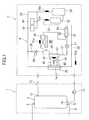
Fig. 1 is a schematic diagram showing heat pump type hot-water supply
equipment according to an embodiment.
Fig. 2 is a schematic block diagram showing a control unit of a refrigerant circuit
according to the embodiment.
Fig. 3 is a flowchart showing operating processes of the refrigerant circuit
according to the embodiment.
Fig. 4 is a schematic diagram showing a receiver of the refrigerant circuit
according to the embodiment.
Fig. 5 is a schematic diagram showing a deformation example of the receiver of
the refrigerant circuit according to the embodiment.
Fig. 6 is a diagram showing the relationship among outside air temperatures,
superheat degrees of the refrigerant of the outlet of the evaporator, target receiver
temperatures, and the amount of refrigerant stored in the receiver.
Fig. 7 is a schematic diagram showing conventional heat pump type hot-water
supply equipment.
Best Mode for Carrying Out the Invention
Next, a specific embodiment of a refrigerating apparatus according to the present
invention will be explained in detail with reference to the drawings. Fig. 1 shows a
schematic diagram of heat pump type hot-water supply equipment using a refrigerating
apparatus according to the present invention. This heat pump type hot-water supply
equipment is equipped with a tank unit 1 and a heat source unit 2, and heats water (hot
water) of the tank unit 1 by the heat source unit 2.
The tank unit 1 includes a hot-water reservoir tank 3, and the hot water stored in
the hot-water reservoir tank 3 is supplied to, for example, a bath tub (not shown). Thus,
in the hot-water reservoir tank 3, there are provided a water supply opening 5 to the bottom
wall thereof, and a tapping hole 6 to the upper wall thereof. Water is supplied from the
water supply opening 5 to the hot-water reservoir tank 3, and hot water of high temperature
is supplied from the tapping hole 6. Further, in the hot-water reservoir tank 3, there are
provided a water intake 10 to the bottom wall thereof, and a hot-water inlet 11 to the upper
part of the side wall (peripheral wall). The water intake 10 and the hot-water inlet 11 are
connected via a circulation path 12. The circulation path 12 is provided with a pump 13
for water circulation and a heat exchange path 14. Further, a channel 8 for water supply
is connected to the water supply opening 5.
The heat source unit 2 is provided with a refrigerant circuit R according to the
present embodiment. This refrigerant circuit R is so configured as to connect, a
compressor 25 for compressing a refrigerant to a pressure higher than the critical pressure,
a hydrothermal exchanger (gas cooler) 26 having the heat exchange path 14, a motor-operated
expansion valve (decompressing mechanism) 27, and an air heat exchanger
(evaporator) 28, in order. That is, the compressor 25 and the gas cooler 26 are connected
via a discharge pipe (refrigerant passage) 29, the gas cooler 26 and the motor-operated
expansion valve 27 are connected via a refrigerant passage 30, the motor-operated
expansion valve 27 and the evaporator 28 are connected via a refrigerant passage 31, and
the evaporator 28 and the compressor 25 are connected via a suction pipe (refrigerant
passage) 33 having an accumulator 32. As a refrigerant, a natural system refrigerant such
as carbon dioxide (CO2) is used. Note that the gas cooler 26 used as a hydrothermal
exchanger has a function of cooling a refrigerant of high temperature and high pressure
which has been compressed in the compressor 25. Further, to the discharge pipe 29, an
HPS 40 used as a pressure protection switch and a pressure sensor 41 are provided.
Further, the refrigerant circuit R is provided with a liquid-gas heat exchanger 34
for cooling the refrigerant of high pressure and high temperature flown out from the gas
cooler 26. The liquid-gas heat exchanger 34 has, for example, a double pipe structure
which includes a first passage 35 through which the refrigerant flown out from the gas
cooler 26 flows, and a second passage 36 through which the refrigerant flown out from the
evaporator 28 flows. That is, the first passage 35 forms a part of the refrigerant passage
30, and the second passage 36 forms a part of the suction pipe 33. With this structure, the
refrigerant of high pressure and high temperature flowing through the first passage 35 and
the refrigerant of low pressure and low temperature flowing through the second passage 36
perform a heat exchange. Then, the refrigerant flown out from the gas cooler 26 is
supercooled. Further, the refrigerant before flown into the accumulator 32 is heated. As
such, a wet operation can be prevented.
Further, the refrigerant circuit R is provided with a defrost bypass circuit 38 for
connecting the discharge pipe 29 and the refrigerant passage 31. The defrost bypass
circuit 38, having a defrost valve 39, is used to perform a defrost operation for supplying
hot gas discharged from the compressor 25 to the evaporator 28 so as to remove frost on
the evaporator 28. For this purpose, the heat source unit 2 is provided with a defrost
control device (not shown) which switches between the normal water heating operation
and the defrost operation. In a case that the water heating operation is performed as a
normal operation, the gas cooler 26 works as a condenser so as to heat hot water flowing
through the heat exchange path 14. On the other hand, in a case that the defrost operation
is performed, the motor-operated expansion valve 27 is set to a predetermined opening and
the defrost valve 39 is set to be in the opening state, whereby hot gas flows into the
evaporator 28. Then, the evaporator 28 is heated by the hot gas, so that frost on the
evaporator 28 is removed. Note that the defrost control device is formed of a
microcomputer, for example.
Further, the refrigerant circuit R is branched at the high-pressure side, and is
provided with a bypass circuit 42 for connecting the branch portion and the downstream
portion located downstream of the branch portion. The bypass circuit 42 has a receiver
43. In between the receiver 43 and the downstream portion in the bypass circuit 42, there
is provided a adjusting valve 44 for adjusting flow rate. In other words, the bypass circuit
42 includes, a first passage 45 connecting the upstream portion of the gas cooler 26 and the
receiver 43, and a second passage 46 connecting the downstream portion located
downstream of the upstream portion of the gas cooler 26 and the receiver 43, and the
second passage 46 is provided with the adjusting valve 44.
In the receiver 43, there is provided a passage 47 which forms a part of the
refrigerant passage 31, as shown in Fig. 4. The receiver 43 (the high-pressure refrigerant
flown into the receiver 43 via the bypass circuit 42) and the low-pressure refrigerant
flowing through the passage 47 perform a heat exchange. That is, the low-pressure
refrigerant flowing through the passage 47 constitutes a cooler (heat exchanger) S for
bringing the temperature of the receiver 43 (high-pressure refrigerant in the receiver 43)
close to the target receiver temperature which will be described below.
The target receiver temperature is, for example, determined corresponding to the
season. When the temperature of the receiver 43 comes close to the target receiver
temperature, the equipment can be operated with the optimum amount of the circulated
refrigerant, so that an excessive superheat operation and a wet operation can be prevented.
The target receiver temperature is determined corresponding to the season by performing a
preliminary test or the like beforehand using the heat pump type hot-water supply
equipment.
As shown in Fig. 2, the control unit of the heat pump type hot-water supply
equipment includes, a receiver temperature detector 50, an air heat exchanger temperature
detector 51, a suction pipe temperature detector 52, an outside air temperature detector 53,
setting means 54 for setting the target receiver temperature, and a controller 55 into which
data (value) from each of the detectors 50, 51, 52, 53 and the setting means 54 is input.
The controller 55 adjusts the opening of the adjusting valve 44. By adjusting the
opening of the adjusting valve 44 so as to bring the temperature of the receiver 43 close to
the target receiver temperature, the controller 55 controls (adjusts) the amount of the
refrigerant stored in the receiver 43 (the amount of the refrigerant flowing through the
inside of the receiver 43). Thereby, the refrigerant temperature in the receiver 43 is
controlled (adjusted). That is, the refrigerant temperature in the receiver 43 is made to the
expected temperature (target receiver temperature) by adjusting the opening of the
adjusting valve 44 to thereby control the density of the refrigerant in the receiver 43. This
can bring the refrigerant amount stored in the receiver 43 to the proper amount. As a
result, the amount of the circulated refrigerant can be made to be optimum. Note that the
controller 55 is formed of, for example, a microcomputer.
As shown in Fig. 1, in the present embodiment, the receiver temperature detector
50 consists of a receiver thermistor 50a provided to the receiver 43, the air heat exchanger
temperature detector 51 consists of an air heat exchange thermistor 51a provided to the
evaporator 28, the suction pipe temperature detector 52 consists of a suction pipe
thermistor 52a provided to the suction pipe 33, and the outside air temperature detector 53
consists of an outside air thermistor 53a. The discharge pipe 29 is also provided with a
discharge pipe thermistor 56a for detecting the temperature of the discharge pipe.
Next, the driving operation of the heat pump type hot-water supply equipment
(water heating operation) will be described.
First, the compressor is driven while the pump 13 for water circulation is also
driven (operated). Then, stored water (hot water) flows out from the water intake 10
provided to the bottom of the hot-water reservoir tank 3. Then, the hot water flown out
flows through the heat exchange path 14 of the circulation path 12. At this time, the hot
water is heated (boiled) by the hydrothermal exchanger 26 which is a gas cooler. The
heated hot water flows into the upper part of the hot-water reservoir tank 3 from the hot
water inlet 11. By continuing this operation, hot water is stored in the hot-water reservoir
tank 3.
It should be noted that under the current Japanese electricity rate system, the
electricity rate of the night time is lower than that of the day time. Therefore, in order to
reduce the cost, it is preferable that the heat pump type hot-water supply equipment is
operated in the midnight time zone.
Further, the water heating operation of the heat pump type hot-water supply
equipment is performed according to the flowchart shown in Fig. 3.
First, a user sets, for example, the tapping temperature by using a remote
controller. Further, the outside air thermistor 53a detects the outside air temperature, and
the temperature (data) detected is input into the controller 55.
Next, as shown as step S1, the target tapping temperature is determined (set) and
the target temperature of the discharge pipe is determined (set).
Here, the required amount of the circulated refrigerant differs depending on the
season, that is, depending on the outside air temperature. As such, in order to operate
with the optimum amount of the circulated refrigerant, the target receiver temperature is
determined (set) beforehand based on the outside air temperature detected and the past data
(data obtained by the preliminary test or the like), and based on the target receiver
temperature determined, the opening (initial opening) of the adjusting valve 44 is set, as
shown as step S2.
Next, as shown as step S3, the target tapping temperature is controlled and the
target temperature of the discharge pipe is controlled. The control of the target tapping
temperature means that the tapping temperature is set to the target tapping temperature.
The control of the target temperature of the discharge pipe means that the opening of the
motor-operated expansion valve 27 is adjusted (controled) to thereby set the temperature of
the discharge pipe 29 to the target temperature of the discharge pipe.
Further, during operation, the receiver thermistor 50a, the air heat exchange
thermistor 51a, the suction pipe thermistor 52a, and the outside air thermistor 53a detect
the temperature of the receiver 43, the temperature of the air heat exchanger, the
temperature of the suction pipe, and the outside air temperature, and then the detected
temperatures (data) are input into the controller 55.
Here, when the outside air temperature becomes higher, it is required to increase
the amount of the circulated refrigerant, that is, to reduce the amount of the refrigerant
stored in the receiver 43. In order to reduce the refrigerant amount stored in the receiver
43, the density of the refrigerant in the receiver 43 should be lowered, and in order to lower
the density of the refrigerant in the receiver 43, the temperature of the receiver 43 should
be raised. As such, in order to operate the equipment with the optimum amount of the
circulated refrigerant when the outside air temperature becomes higher, the temperature of
the receiver 43 should be raised. In turn, when the outside air temperature becomes lower,
the temperature of the receiver 43 should be lowered.
Further, when the superheat degree of the refrigerant at the outlet of the
evaporator 28 becomes larger, it is required to increase the amount of the circulated
refrigerant, that is, to reduce the amount of the refrigerant stored in the receiver 43,
Therefore, as same as the aforementioned, in order to operate the equipment with the
optimum amount of the circulated refrigerant when the superheat degree becomes larger,
the temperature of the receiver 43 should be raised. In turn, when the superheat degree
becomes smaller, the temperature of the receiver 43 should be lowered.
Now, the controller 55 computes the superheat degree of the refrigerant at the
outlet of the evaporator 28 based on the detected air heat exchanger temperature and the
suction pipe temperature, and calculates the target receiver temperature based on the
detected outside air temperature, the calculated superheat degree and the past data. Then,
the controller 55 judges whether the target receiver temperature calculated coincides with
the target receiver temperature having been set beforehand. If judges that the target
receiver temperature calculated is different from the target receiver temperature set
beforehand, the controller 55 corrects the target receiver temperature to the target receiver
temperature which is calculated from the target receiver temperature set beforehand
("calculates the target receiver temperature" shown as step S4). This means that the
optimum amount of the circulated refrigerant for the current operational state may not be
obtained at the target receiver temperature set in step S2 in some cases, since the
condensation load and the cooling load have been fluctuated. Therefore, in this step S4,
the target receiver temperature, with which the amount of the circulated refrigerant is made
to be optimum, is calculated.
Next, moving to step S5, the controller 55 compares the detected temperature of
the receiver 43 with the target receiver temperature corrected. That is, in step S5, the
detected temperature of the receiver 43 and the target receiver temperature (the target
receiver temperature which has been corrected) are judged whether they coincide with each
other.
If the detected temperature of the receiver 43 and the target receiver temperature
corrected are judged that they coincide with each other, the operation for controlling the
target tapping temperature and the operation for controlling the target temperature of the
discharge pipe are continued (step S3).
In contrast, if the detected temperature of the receiver 43 and the target receiver
temperature corrected are judged to be different, the operation moves to step S6. Then,
the controller 55 performs an EVB opening adjustment (opening adjustment of the
adjusting valve 44) so as to adjust the refrigerant amount stored in the receiver 43. If the
detected temperature of the receiver 43 is higher than the target receiver temperature
corrected, the adjusting valve 44 is choked. If the detected temperature of the receiver 43
is lower than the target receiver temperature corrected, the adjusting valve 44 is released.
With this step, the temperature of the receiver 43 can come close to the target receiver
temperature corrected so that the amount of the circulated refrigerant can be made to the
expected amount corresponding to the current operational state (operational condition).
For example, the optimum amount of the circulated refrigerant in the summer (the
outside air temperature is about 32°C) is larger than the optimum amount of the circulated
refrigerant in the winter (outside air temperature is about -5°C). Therefore, in the winter,
the temperature of the receiver 43 is controlled so as to come close to the target receiver
temperature of the winter, to thereby store in the receiver 43 the amount of the refrigerant
corresponding to the difference between the optimum amount of the circulated refrigerant
for the summer and the optimum amount of the circulated refrigerant for the winter.
Thereby, the amount of the circulated refrigerant in the winter becomes less than the
amount of the circulated refrigerant in the summer. On the other hand, in the summer, the
temperature of the receiver 43 is controlled so as to come close to the target receiver
temperature of the summer, to thereby cause the amount of the refrigerant stored in the
receiver 43 during the winter to flow out. Thereby, the amount of the circulated
refrigerant in the summer becomes larger than the optimum amount of the circulated
refrigerant in the winter.
Fig. 6 shows the relationship among the outside air temperature, the superheat
degree of the refrigerant at the outlet of the evaporator 28, the target receiver temperature,
and the refrigerant amount stored in the receiver 43 (the amount of the refrigerant flowing
through the inside of the receiver 43), which are obtained from experimentations using the
heat pump type hot-water supply equipment according to the present embodiment. The
heat pump type hot-water supply equipment used in the experimentations includes the
receiver 43 with the capacity of 400cc and the pressure inside the receiver 43 is 11 Mpa.
As is obvious in Fig. 6, when the outside air temperature becomes higher, the
target receiver temperature becomes higher. This is because that as the outside air
temperature becomes higher, the amount of the circulated refrigerant must be increased,
that is, the refrigerant amount in the receiver 43 must be reduced. In order to reduce the
refrigerant amount in the receiver 43, the target receiver temperature must be raised. As
such, the target receiver temperature becomes higher as the outside air temperature
becomes higher.
Further, as is obvious in Fig. 6, as the superheat degree becomes larger, the target
receiver temperature becomes higher. This is because that as the superheat degree
becomes larger, the amount of the circulated refrigerant must be increased, that is, the
refrigerant amount in the receiver 43 must be reduced. In order to reduce the refrigerant
amount in the receiver 43, the target receiver temperature must be raised. As such, the
target receiver temperature becomes higher as the superheat degree becomes larger. By
raising the target receiver temperature, the superheat degree becomes smaller.
In this way, the equipment can be operated with the amount of the circulated
refrigerant corresponding to the season (condition) regardless of the fluctuation in the
outside air temperature along with the season's transfer. Thereby, an excessive superheat
operation and a wet operation can be prevented. Consequently, the reliability of the
compressor 25 is improved. Further, by controlling the amount of the circulated
refrigerant as described above, the heat pump type hot-water supply equipment having the
refrigerant circuit R can exhibit the ability to the maximum.
Further, the controller 55 can adjust the refrigerant temperature in the receiver 43
by controlling the temperature of the receiver 43 so as to come close to the target receiver
temperature set corresponding to, for example, the season. Thereby, the density of the
refrigerant stored in the receiver 43 can be controlled, so that the refrigerant amount stored
in the receiver 43 can be adjusted. Thus, the refrigerant amount stored in the receiver 43
can be adjusted to the amount corresponding to the season, so that the amount of the
circulated refrigerant is made to the amount corresponding to the season. Therefore, an
excessive superheat operation and a wet operation can be prevented.
Further, the controller 55 calculates the target receiver temperature based on the
outside air temperature and the superheat degree serving as indexes for controlling the
amount of the circulated refrigerant. Therefore, it is possible to ensure the amount of the
circulated refrigerant to be the expected amount (for example, amount of the circulated
refrigerant corresponding to the season).
Further, in step S4, the target receiver temperature is corrected based on two
indexes which are the outside air temperature and the superheat degree. Therefore, it is
possible to control the amount of the circulated refrigerant with higher precision.
Further, the controller 55 brings the temperature of the receiver 43 close to the
target receiver temperature by adjusting the opening of the adjusting valve 44. Therefore,
the amount of the circulated refrigerant can be controlled by such a simple control as
adjusting the opening of the adjusting valve 44.
Further, the controller 55 corrects, from time to time during operation, the target
receiver temperature based on the outside air temperature and the superheat degree, while
adjusting, from time to time during operation, the adjusting valve 44 to be the opening
corresponding to the target receiver temperature adjusted. Thus, the temperature of the
receiver 43 can surely come close to the target receiver temperature corrected. Thereby,
the refrigerant amount stored in the receiver 43 can be made to the amount corresponding
to, for example, the season, so that the amount of the circulated refrigerant can be made to
the amount corresponding to the season. This can prevent an excessive superheat
operation and a wet operation.
Further, since the adjusting valve 44 is provided to the second passage 46 of the
bypass circuit 42, the controller 55 can surely control the refrigerant amount stored in the
receiver 43 provided to the bypass circuit 42 by adjusting the opening of the adjusting
valve 44. Therefore, the amount of the circulated refrigerant is ensured to be the expected
amount.
Further, since the receiver 43 and the low-pressure refrigerant flowing through the
passage 47 perform a heat exchange, the receiver 43 can be cooled by the low-pressure
refrigerant. Therefore, the temperature of the receiver 43 can easily come close to the
target receiver temperature without any additional cooler.
Although the aforementioned embodiment sets a target receiver temperature and
then corrects the target receiver temperature based on the detected outside air temperature
and the computed superheat degree, the target receiver temperature may be corrected
(calculated) based solely on the outside air temperature or the superheat degree. Here,
since the outside air temperature is detected by the outside air thermistor 53a, the outside
air temperature can be detected without a calculation. Therefore, if the target receiver
temperature is calculated based on the outside air temperature, it is possible to simplify the
calculation for controlling the amount of the circulated refrigerant. Further, the
magnitude of the superheat degree has a close relationship with the degree of the superheat
operation. Therefore, if the target receiver temperature is calculated based on the
superheat degree, the amount of the circulated refrigerant can be controlled with high
precision.
Further, although the aforementioned embodiment shows processes from step S1
to step S6 in the flowchart of Fig. 3, step S4 and step S5 may be omitted. That is, the
superheat degree may be calculated based on the temperature of the air heat exchanger and
the temperature of the suction pipe, and based on the detected outside air temperature and
the calculated superheat degree, the opening of the adjusting valve 44 may be determined.
This enables to adjust the refrigerant amount stored in the receiver 43, whereby the amount
of the circulated refrigerant can be made to the expected amount corresponding to the
operational state. At this time, it is not required to calculate (correct) the target receiver
temperature, to compare the temperature of the receiver 43 with the calculated (corrected)
target receiver temperature, and the like, which enable to simplify the control of the
amount of the circulated refrigerant. Further, in the case of omitting step S4 and step S5,
the opening of the adjusting valve 44 can be determined based on at least one of the
outside air temperature or the superheat degree.
Further, the receiver 43 may be configured in such a manner as to cause the high-pressure
refrigerant to flow and to cause the receiver 43 (the high-pressure refrigerant
flown) and the low-pressure refrigerant to perform a heat exchange. Therefore, the first
passage 45 of the bypass circuit 42 may be branched from the discharge pipe 29, the gas
cooler 26 or the refrigerant passage 30, and the second passage 46 may be connected to the
discharge pipe 29, the gas cooler 26 or the refrigerant passage 30 which are located
downstream of the aforementioned branch portion. That is, the first passage 45 and the
second passage 46 may be provided to the upstream side of the decompressing mechanism
(motor-operated expansion valve) 27 in the high-pressure side of the refrigerant circuit R.
However, the first passage 45 and the second passage 46 must be so formed as to generate
a pressure difference between the first passage 45 and the second passage 46.
Further, the low-pressure refrigerant performing a heat exchange with the receiver
43 may be the low-pressure refrigerant flowing through the suction pipe 33. Moreover, in
order to perform the heat exchange, the passages for the low-pressure refrigerant such as
the refrigerant passage 31 and the suction pipe 33 may be formed along the outer surface of
the receiver 43 as shown in Fig. 5. Moreover, the passages for the low-pressure
refrigerant may be coiled to the outer peripheral of the receiver 43, although this is not
shown.
As described above, although a specific embodiment of the present invention has
been explained, this invention is not limited to the aforementioned embodiment and is able
to be carried out with various changes within the scope of the invention. For example, the
refrigerant circuit R can be applied to a refrigerant circuit of any type of refrigerating
apparatus such as an air conditioning apparatus or a showcase, other than heat-pump type
hot-water supply equipment. Further, as a refrigerant, a natural system refrigerant
(supercritical refrigerant) other than carbon dioxide, such as ethylene, ethane or nitrogen
oxide, may be used. Further, as a cooler S for cooling the receiver 43 (high-pressure
refrigerant in the receiver 43), a fan device or other cooling devices may be used instead of
using a low-pressure refrigerant, and moreover, a part of the evaporator 28 may also be
used. Further, as the adjusting valve 44, not only a motor-operated valve but also a
solenoid valve or other open/close valves may be used. Further, as the decompressing
mechanism 27, not only a motor-operated expansion valve but also a capillary tube may be
used. Further, the receiver 43 and the heat exchanger (liquid-gas heat exchanger) 34
shown in Fig. 1 may be arranged in reverse order.
Industrial Applicability
As described above, the refrigerating apparatus according to the present invention
is available for a heat source unit of heat-pump type hot-water supply equipment.